


Conventional
Table of contents
 Loading...
OPERATOR’S
MANUAL

Quick Table of Conte nts
•Introduction............................................1
•Cab And Frame Access............................5
•Getting To Your Engine .................................9
•Controls And Disp lays ...................................16
•Seat And Restraint Systems............................. 63
•Driver’s Checklists ................................................76
•Starting And Operating The Vehicle........................ 80
•Maintenance and Ser vice. ........................................ 112
•V ehi cle Identification.................................................... 184
•Consumer Inf o rma tion .................................................... 185
•Subject Index ............................................................ 187
California
Proposition 65 Warning
• Diesel engine exhaust and some of its constituents are
known to the State of California to cause cancer, birth
defects, and other reproductive harm.
• Other chemicals in this vehicle are also known to the
State of California to cause cancer, birth defects or
other reproductive harm.
• Battery posts, termi nals, and related accessor ies con-
tain lead and lead compounds, chemicals known to the
State of California to cause cancer and reproductive
harm. Wash hands after handling.

PART 1: INTRODUCTION
This manual contains useful information for the safe and efficient
operation of your Peterbilt vehicle. It also provides information on
maintaining your vehicle in the best condition, with an outline for performing safety checks and basic preventive maintenance inspections.
We have tried to present the information you’ll need to learn about
your vehicle’s functions, controls, and operation - and to present it as
clearly as possible. We hope you’ll find this manual easy to use.
Please remember, though -- this manual is not a training manual. It
can’t tell you everything you need to know about driving your Peterbilt
vehicle. For that you need a good training program or truck driving
school. If you have not been trained, get the proper training before
you drive. Only qualified d rivers should drive this vehicle.
There will be times when you need to take this manual out of your
Peterbilt. When you do, please be sure to return it to the cab when
you are finished using it. That way it will be there when you need it
the next time or when you pass the vehicle on to the next user.
How to Find What You Want
There are several tools built into this manual to help you find what y ou
need quickly and easily.
First is the Quick Table of Contents. Located at the front of the
manual, this lists the main subject s c overed and gives pa ge num bers
where you can find these subjects. Use the Quick Table of Con tents
to find information on a large subject like “Maintenance.”
Cross-referenced citations also help you get the information you
need. If some other par t of the manual contains fur ther information
on the subject you are reading about, we’ll indicate that in a cross-reference like this: (See PART 6: DRIVER’S CHECKLIST
have to go searching for more information.
Finally you’ll find a helpful Subject Index. It’s in the back of the manual and alphabetically lists the subjects covered. So if you want information on brakes, for example, just look under Bra ke
Index. You’ll find all the pages listed where brakes or braking are discussed.
). You won’t
in the Subject
A Special Word about Repairs
Your Peterbilt dealer’s ser vice center is the best place to have your
vehicle repaired. You can find Peterbilt dealers all over the country
with the equipment and trained personnel to get you back on the road
quickly - and keep you there.
Your vehicle is a complex machine. Anyone attempting repairs on it
needs good mechanical training and the proper tools. If you are sure
you have these requirements, then you can probably perform some
repairs yourself. However, all warranty repairs must be performed by
an autho rized Peterbilt se rvice facility. If you aren ’t an experie nced
mechanic, or don’t have the r ight equipm ent, plea se leave all repairs
PB1317 (CAT. NO. 5229 ) —1— 22-01510 (R12/01)

PART 1: INTRODUCTION
to an aut horized ser vice facility. They are the one s equipped to d o
the job safely and correctly.
WARNI NG! Attempting repair work without sufficient
training, service manuals, and the proper tools can be
dangerous. You could be injured or you could make
your truck unsafe. Do only those tasks you are fully
qualifie d to do.
Maintenance Manuals. If you do decide to do any complex repair
work, you’ll need the Peterbilt Maintenance manuals. Order them
from your authorized dealer. Please provide your Chassis Serial
Number when you order, to be sure you get the correct manuals for
your vehicle. Allow about four weeks for delivery. There will be a
charge for these manuals.
Final Chassis Bill of Material. A complete, nonillustrated computer
printout listing of the parts used to cust om -build your Peterbilt vehicle
is available through the Peterbilt dealer from whom your p urchased
your vehicle.
WARNI NG! Modifying your vehicle can make it unsafe.
Some modifications can affect your truck’s electrical
system, stability, or other impor tan t functions. Before
modifying your vehicle, check with your dealer to make
sure it can be done safely.
Additional Sources of Information
Operator’s manuals are also s upplied by the manuf act urers of components such as the engine, seats, transmission, and radio in your
Peterbilt. If you are missing any of these manuals, ask your Peterbilt
dealer to supply them.
Your new Peterbilt’s glove box also contains a copy of the Tru ck
Driver’s Handbook, published by the American T rucking Association.
Refer to it for important information on driving your vehicle. Another
place to learn more about trucking is a local truck driving school.
Contact one near you to find out what kinds of instruction it offers.
Federal and state agencies also have information you can ask for.
The Interstate Commerce Commission can give you information
about regulations governing transportation across state lines. And
various agencies in state governments are sources for regulations
that differ from state to state.
Warnings
We’ve put a number of warning m essages in this manual. They are
there for your protection and information. Please read them and follow them. They can h elp you to avoid injury to yourself and your passengers as well as to p revent costly damage to your vehicle. We’ve
PB1317 (CAT. NO. 5229 ) —2— 22-01510 (R12/01)

PART 1: INTRODUCTION
used certain symbols and “signal words” to indicate what kind of message is going to follow. When you see these symbols & words, you
know that you need to p ay special attention. P lease don’t ignore any
of these signals.
WARNI NG!
When you see this symbol & word, the message that fo llows is especially vital. This signals something that c an cause serious injury or
death. This message will tell you what the hazard is, what can happen if you don’t heed the warning, and how to avoid it. For examp le:
WARNI NG! Attempting repair work without sufficient
training, service manuals, and the proper tools can be
dangerous. You could be injured or you could make
your vehicle unsafe. Do only those tasks you are fully
qualifie d to do.
CAUTION:
This symbol & word signals something that could damage your vehicle. And you might receive an injur y, too. For example:
CAUTION: Continuing to operate a vehicle with insufficient oil pressure will cause serious engine damag e .
NOTE:
Gives you information we feel you ’d like to have. It could have to do
with care of your vehicle or with driving more efficiently:
NOTE: A cold compressor can cause refrigerant to liquefy
and warp the valve plates or cause a hydraulic lock. Warm
the engine before starting the air conditioner.
Please take the time to read these messages when you see the m.
And remember:
WARNING! Something that could injure you seriously.
CAUTION: Something that could cause injury to you or your
vehicle.
NOTE: Useful information.
PB1317 (CAT. NO. 5229 ) —3— 22-01510 (R12/01)

PART 1: INTRODUCTION
Vehicle Safety
Make sure your Peterbilt is in top working condition before heading
out on the road—it is the
the vehicle according to PART 6: DRI VER ’ S C HE CKL IST
WARNING! Do not drink and drive. Your reflexes, perceptions, and judgment can be affected by even a small
amount of alcohol. Y ou could have a serious—or even fatal
accident—if you drive after drinking. Please do not drink
and drive or ride with a driver who has been drinking.
WARNING! The use of alcohol, drugs, and certain medications will seriously impair perception, reactions, and driving ability . These cir cumstances can substantiall y increase
the risk of an accident and personal injury.
Please remember, this manual is not a training manual. It cannot tell
you everything you need to know about driving your Peterbilt vehicle.
For that you need a good t raining program or truck d riving school. If
you have not been trained, get the proper training before you drive.
Only qualified drivers should drive this vehicle.
Every new Peterbilt vehicle is designed to conform to all Federal
Motor Vehicle Safety Standards applicable at the time of manufacture.
However, even with these safety featu res, continued safe and reliable
operation depends greatly upon regular vehicle maintenance. The
vehicle must be operated within the range of its mechanical capabilities and the limits of its load ratings. (See the Tire and Rim Weight
Ratings label on the driver's door edge.)
responsible
driver's duty to do so. Inspect
.
PB1317 (CAT. NO. 5229 ) —4— 22-01510 (R12/01)
PART 2: GETTING INTO AND OUT OF THE
CAB AND FRAME ACCESS
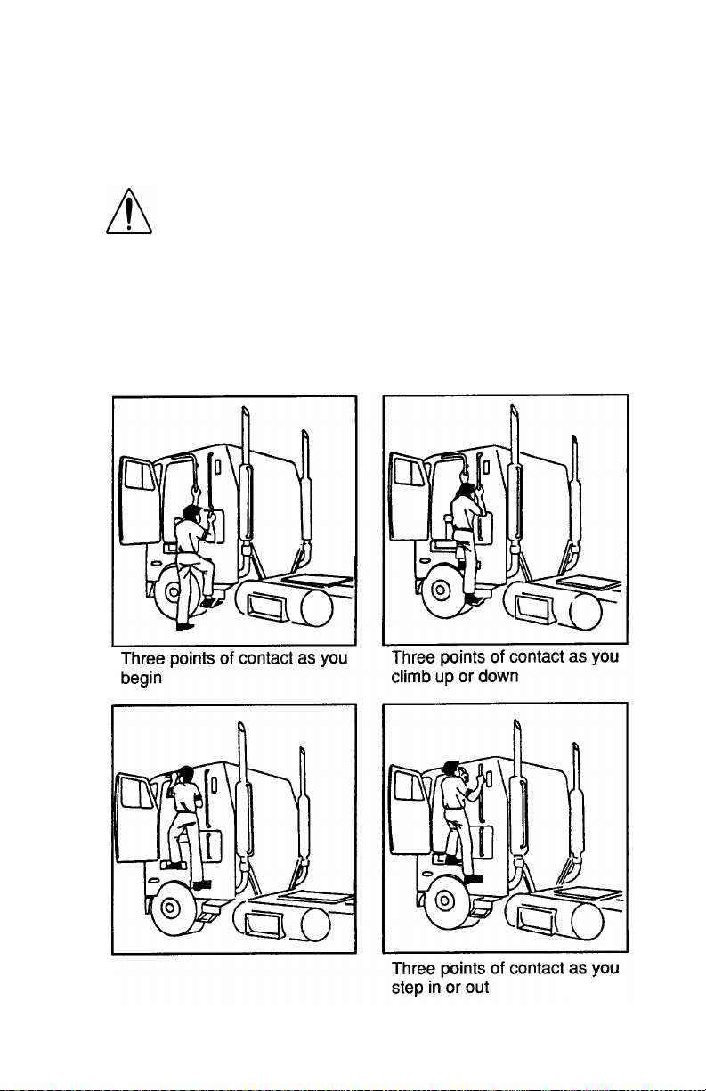
Be careful whenever you get into or out of your vehicle’s cab.
Whether you have a COE or conventional cab, always maintain at
least three points of contact with your hands on the grab handles and
your feet on the steps.
WARNING! Jumping out of the cab or getting into the
cab without proper caution is dangerous. You could slip
and fall, possibly suffering a serious injury. Keep steps
clean. Clean any fuel, oil, or grease off of the steps
before entering the cab. Use the steps and grab handles provided, and always keep at least three points of
contact between your hands and feet and the truck.
Look where you are going.
COE: The pictures below show the best way to enter and exit a COE
cab.
02957
PB1317 (CAT. NO. 5229 ) —5— 22-01510 (R12/01)
PART 2: GETTING INTO AND OUT OF THE
CAB AND FRAME ACCESS
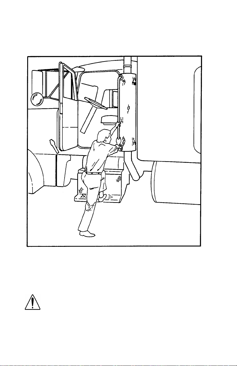
CONVENTIONAL: The picture below shows the best way to enter
and exit a Conventional Cab.
02958
Door Lock and Keys
Doors can be l ocked from the inside by us i ng the lock b utton. Close the
door then push the button down to lock. Doors automatically unlock
when you open them from inside, and can be locked from the outside
with the k ey only.
WARNING! To lessen the chance and/or severity of p ersonal injury in case of an accident, always lock the
doors while driving. Along with using the lap/shoulder
belts proper ly, locking the doors helps prevent occu pants from being thrown from the vehicle.
To lock or unlock the doors from outside the cab, insert the key in the
lock.Turn the key toward the rear to lock; forward to unlock.
PB1317 (CAT. NO. 5229 ) —6— 22-01510 (R12/01)
PART 2: GETTING INTO AND OUT OF THE
CAB AND FRAME ACCESS
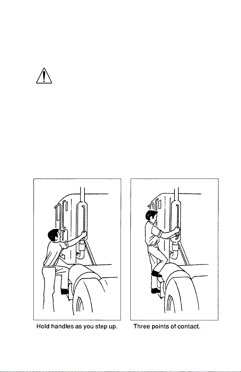
Climbing Onto the Deck Plate
When you are climbin g onto and of f the deck plate, maintain a t least
three points of contac t with your hands on the grab ha ndles and your
feet on the steps.
WARNI NG!
•
You can be hur t if you aren’t careful climbing onto
and off the deck plate. You can slip and fall, especially if the surfaces are wet or icy, or if you step in
oil, fuel, or grease. Keep steps clean. Always maintain at least three points of contact between your
hands and feet and the steps and deck plate.
•
Do not climb onto and off the deckplate–use steps
and grabhandle provided. If there is no de ck plate,
or if proper steps and grab handles aren’t provided,
don’t climb on t o t he ar ea behind the cab . Peter bi lt
did not intend for the area to be a step if handrails or
proper steps are not provided.
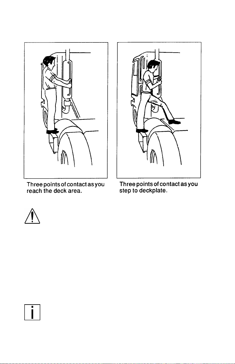
The pictures below show you the right way to get on and off the area
behind your cab.
02959
PB1317 (CAT. NO. 5229 ) —7— 22-01510 (R12/01)
PART 2: GETTING INTO AND OUT OF THE
CAB AND FRAME ACCESS
02960
WARNI NG! Do not step on vehicle components without
antiskid surfaces or use components not designed for
entry-and-exit use. You could fall and injure yourself if
you step on a slippery surface. For example:
•
You c o uld fa ll and in jure you rself if you step o nt o a
fuel tank surface. A fuel tank is not a step. The tank
surface can get very slippery, and you might not be
able to prevent a fall. Don’t step onto the surface of a
fuel tank. Use only the step s and handholds provided,
not chain hooks, quarter fenders, etc.
•
Always reinstall steps before entering the cab or
accessing the deck plate. Without steps, you could
slip and fall, resulting in possible injury to yourself.
NOTE: Any alteration (adding bulkheads, headache racks,
tool boxes, etc.) behind the cab or sleeper that affects the
utilizatio n o f grab ha nd les , de ck p lat e s, or fra m e acc es s
steps installed by Peterbilt must comply with FMCSR 399.
PB1317 (CAT. NO. 5229 ) —8— 22-01510 (R12/01)
PART 3: GETTING TO YOUR ENGINE
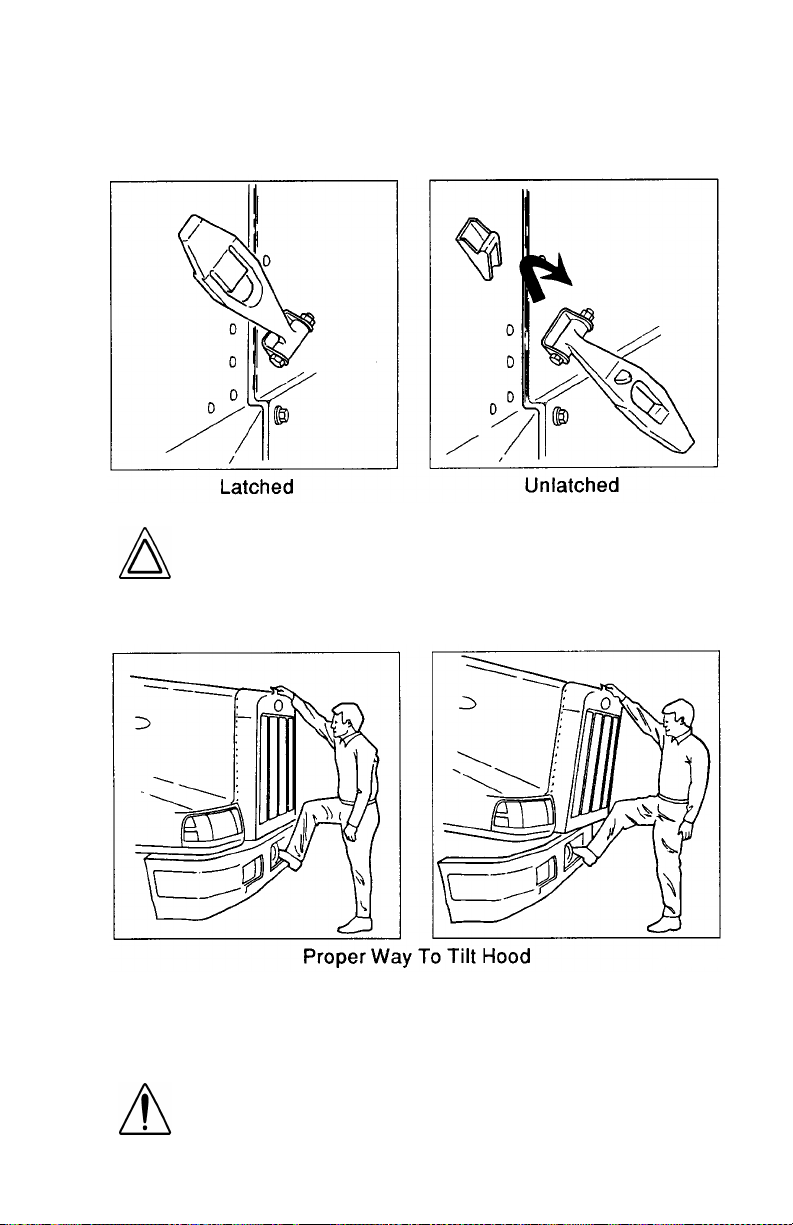
Hood Hold Downs (Conventional Cabs)
Your hood hold downs keep your hood from opening unexpectedly
02961
CAUTION: If you do not latch your hood securely, it
coul d open duri ng oper ation and caus e vehic le dama ge.
Be sure to latch the hood securely.
Hood Tilt (Conventional Cabs)
02962
To open your hood, unlock the hood hold downs by unlatching them.
Put one hand on the top of the hood front, one foot on the bumper,
and one foot on the ground. Tilt the hood forward.
WARNI NG! Before opening or cl osing the hood, be sure
there are no people or objects in the way. A hood could
hurt someone in the way of its descent.
PB1317 (CAT. NO. 5229 ) —9— 22-01510 (R12/01)
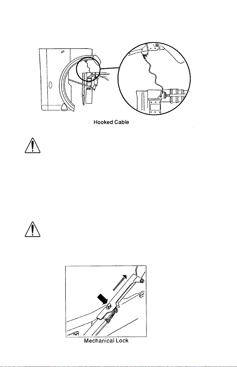
PART 3: GETTING TO Y O UR ENGINE
Safety Cable
02963
WARNING! If the hood falls, anyone under it could be
injured. Always attach the safety cable to keep a hood
open any time anyone gets under a hood for any reason.
To attach the safety cable: The cable is on the driver’s side of the
radiator. Attach it to the hook on the hood.
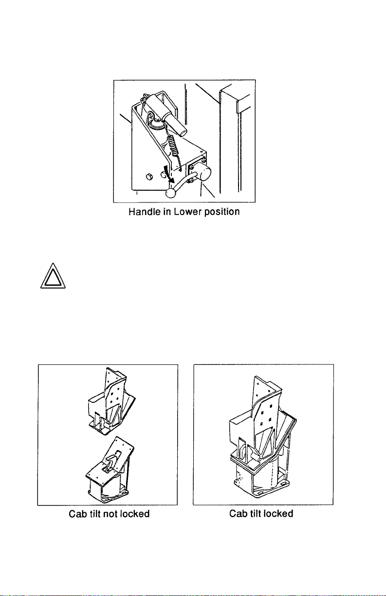
COE Cab Tilt System
If you have a COE type of vehicle, your cab tilts forward for maintenance on the engine and other components. An independent hydraulic system raises and lowers the cab. And a positive dual locking
device increases safety and reduces the danger of mishaps while you
are driving.
WARNING! Getting any part of your body under an
unsecured cab could cause a serious or fatal acciden t.
The cab could fall and crush you. Always make sure the
mechanical lock is fully engaged before getting under
the cab, or before letting anyone else get under it. See
below for instructions on using the mechanical lock.
02964
PB1317 (CAT. NO. 5229 ) —10— 22-01510 (R12/01)

PART 3: GETTING TO YOUR ENGINE
CAUTION: R aising the cab with heavy objects in the
cab, sleeper, or luggage compartment can cause serious damage to the cab tilting mechanism and cab.
Before tilting the cab, remove heavy items such as tire
chains and tools. Remove or stow securely any loose
items. And shut the doors tightly.
Cab tilting instructions are labeled and in stalled on t he base of the
passenger seat in your cab.
WARNI NG! You can be seriously injured by the cab if
you do not follow safety precautions. Whenever you
raise or lower the cab, or when you work under the cab,
please remember the following safety rules:
•
Be sure no one is under the front of the cab. Whether
you are raising or lowering the cab, KEEP CLEAR.
•
Never work under a raised cab unless it is properly
supported. This means use an overhead hoist of sufficient capacity to support the cab safely. Never prop
the cab up instead of using a hoist. The prop could fail
and let the cab fall on you or anyone else working
under the cab.
•
Always be sure the safety latch is engaged when you
or anyone else works under the cab.
•
Perform w ork only when the cab is in th e mechanically
locked position or in the full tilt position.
•
When your cab’s hydraulic system needs ser vi ce or
repair:
- Have maintenance and repair done only by someone
qualified in hydraulic systems.
- Be sure no one tries to bleed the system with the cab
raised. This will defeat the safety system. The cab
can fall and crus h a nyone under it.
- Do not tamper with any part of the cab tilt cylinders,
including removing the velocity fuses. To do so will
defeat their purpose. The cab could fall and crush
anyone under it. If you have any need for repair
involving the velocity fuses, have a qualified truck
mechanic do the work.
NOTE: In case of oil loss i n the syst em or a lo ck-up in the til t
cylinders, refer to the maintenance manual for repair instructions.
PB1317 (CAT. NO. 5229 ) —11— 22-01510 (R12/01)
PART 3: GETTING TO Y O UR ENGINE
To Raise the Cab:
1. Park the vehicle on a lev el surf ace to ensure proper hook and latch
alignment.
2. Apply the parking brake.
3. Make sure the shift lever is in Neut ral. This will prevent the shift
lever from g etting caught on the cab duri ng tilt operation.
4. Secure or remove all loose items in the cab and luggage compartments. Close all doors.
5. Check the clearance above and ahead of the cab. Be sure there
will be enough room to clear roof antennae, roof fairings, and side
extenders when you tilt the cab. Chec k for obstructions overhead,
such as branches, power lines, lights, etc. Check also for obstructions in front, such as walls, work benches, other vehicles, etc.
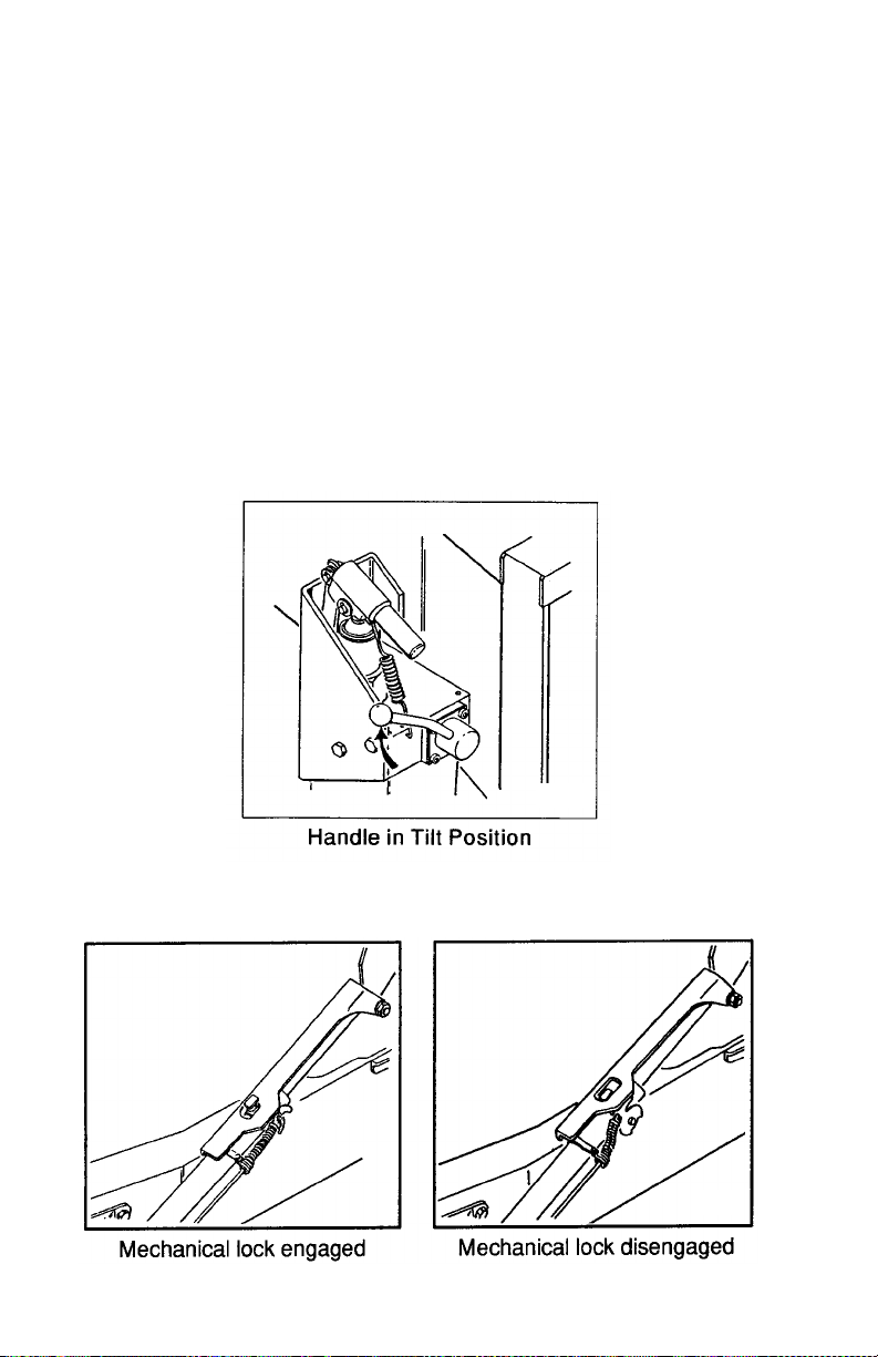
6. Place the control valve handle in the Tilt (Raise) position.
02965
7. Pump the cab up until the mechanical lock engages. Now put the
control valve handle in the center position.
02966
PB1317 (CAT. NO. 5229 ) —12— 22-01510 (R12/01)
PART 3: GETTING TO YOUR ENGINE
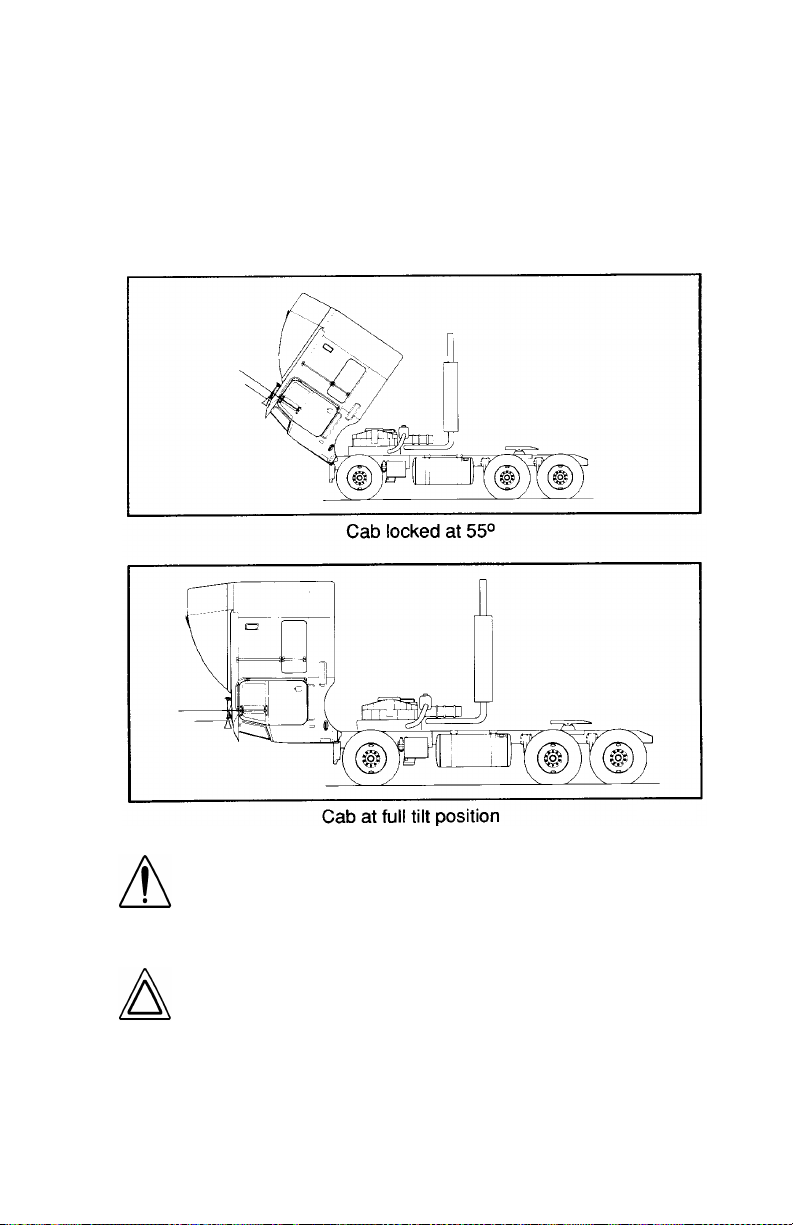
When the cab is raised to the point where the weight of the cab is
greater in front of its hi nges than to the rear, gravity wi l l mak e i t fall forward. It will fall at a controlled rate.
8. If you want the cab in the full forward position, pull the cable to disengage the mechanical lock. You may have to free the lock by
raising or lowering the cab to relieve pressure on the locking
mechanism.
02967
WARNING! When the cab is tilted fully (90°), the roofmounted antenna mast could injure someone. Remove
or flag the mast before tilting the cab a ll the way forward.
CAUTION: When tilting the cab to the full tilt, or vice
versa, hold the safety lock bar up to prevent it from
engaging at the locked position. If it does lock, you r cab
could be severely damaged.
PB1317 (CAT. NO. 5229 ) —13— 22-01510 (R12/01)
PART 3: GETTING TO Y O UR ENGINE
To Lower the Cab
1. Place the control valve handle in the Return (Down) position.
02968
2. Release the mechanical lock. Hold the safety lock bar up.
3. Pump until the cab starts to descend. The valve system will co ntrol the speed in either direction automatically.
CAUTION: Do not try to pump the cab down or hold it
down with hydraul i c force. If you do, ca b damage will
occur.
4. Leave the handle in the down position for at least 20 seconds after
the cab touches down. This allows time for the full spring force to
develop in the cab latch. Inspect the hooks to be sure they are
closed. If they are not properly engaged, raise the cab slightly and
guide the latch, if necessary, w hile lowering the cab.
02969
PB1317 (CAT. NO. 5229 ) —14— 22-01510 (R12/01)

PART 3: GETTING TO YOUR ENGINE
WARNI NG! Placing any part of your body between the
cab and the frame could result in serious injury. Keep
hands and feet out from under the cab if it must be
raised to re-engage the cab latches. Guide the cab from
the outer surfaces only.
5. Return the control valve handle to the Lock (Ce nter) position for
normal operation.
CAUTION:
•
Do not continue to operate the pump after the cab is in
the full Down pos i tio n. Addit io nal pumping could
cause structural damage to the cab.
•
Driving with the cab tilt lock unsecured can damage
your vehicle. Check daily to be sure the lock is closed
securely .
NOTE: In case of oil loss i n the syst em or a lo ck-up in the til t
cylinders, refer to the maintenance manual for repair instructions.
PB1317 (CAT. NO. 5229 ) —15— 22-01510 (R12/01)
PART 4: CONTROLS AND DISPLAYS
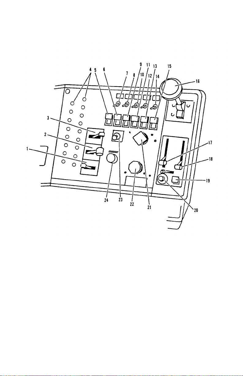
Your Instrument Panel
This part explains the location of t he vari ous feat ures on your vehicle
and describes their function. Fo r informa tion on using these features
in driving, see the paragraphs below. Please remember that each
Peterbilt is custom-made. Your instrument panel may not look exactly
like the one in the pictures below. We have tried to describe all the
most common features and controls available. You can pick out the
parts that apply to you and read them to be fully informed on how your
particular vehicle operates.
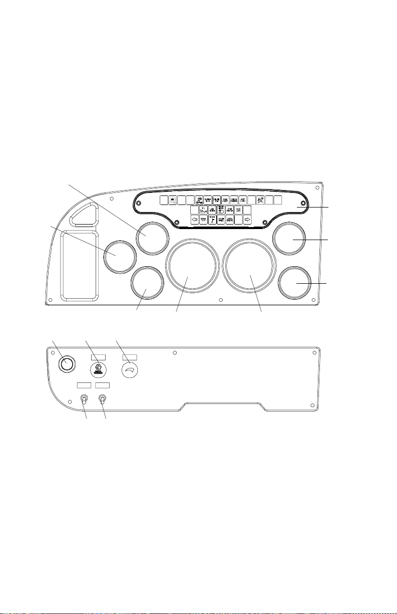
Typical Conventional Cab Instruments and Controls
4
5
3
6
7
Panel A
Panel C
11 12 13
910
1
82
LEFT SIDE
1. Tachometer 8. Speedometer
2. Oil Pressure 9. Clearance Lamps
3. Clock 10. Headlamps
4. Oil Temperature 11. Ignition Key Switch
5. Warning Lamp Clust er 12. Windshield Wiper/Washer
6. Water Temperature 13. Panel Light Dimmer
7. Dual Air Pressure
PB1317 (CAT. NO. 5229 ) —16— 22-01510 (R12/01)
PART 4: CONTROLS AND DISPLAYS
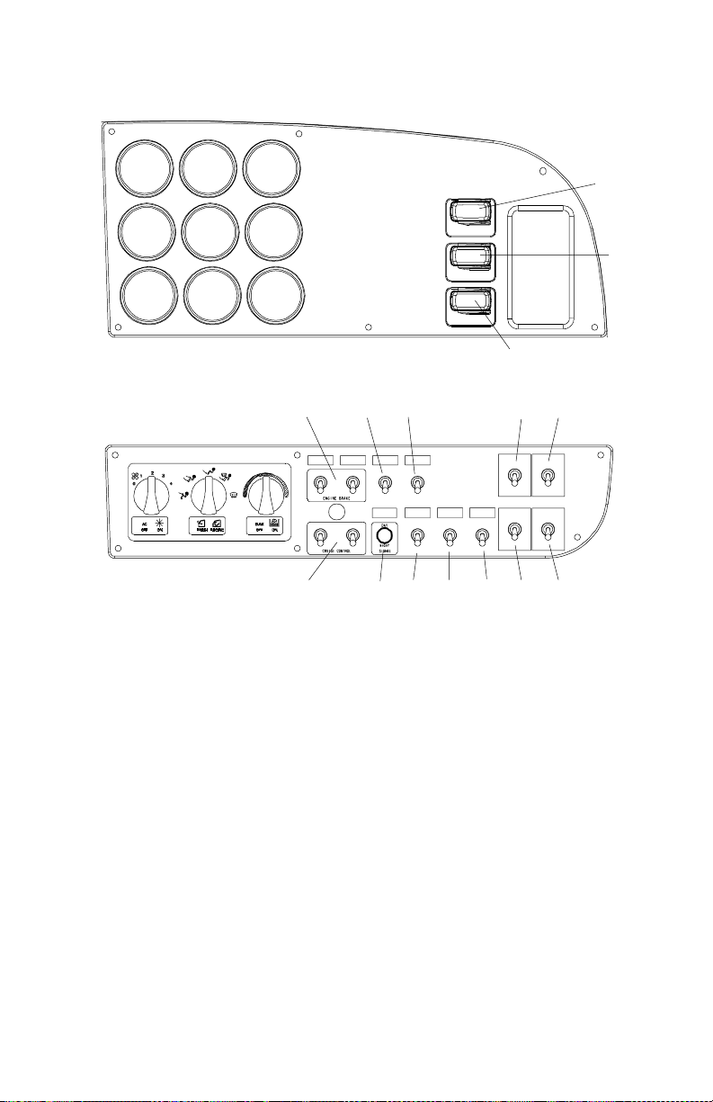
Conventional
12 3
45 6
7 8 9
13 14 15 16 17
RIGHT SIDE
1. Fuel 13. Engine Brake
2. Air Cleaner Restriction 14. Engine Fan
3. Transmission Oil T em perature 15. Fuel Tank Selector
4. Voltmeter 16. LH Air Window
5. Manifold Pressure 17. RH Air Window
6. Front Driver Oil Temperature 18. Sleeper Door Lock
7. Air Applica t ion 19. Ca b D oor Lock
8. Pyrometer 20. RH Mirror
9. Rear Driver Oil temperature 21. Mirror Heat
10. Air Suspension 22. LH Mirror
1 1. Fifth Wheel 23. Day/Night Signal
12. Interaxle Differential Lock 24. Cruise Control
12
10
11
Panel B
18192021222324
Panel D
PB1317 (CAT. NO. 5229 ) —17— 22-01510 (R12/01)
PART 4: CONTROLS AND DISPLAYS
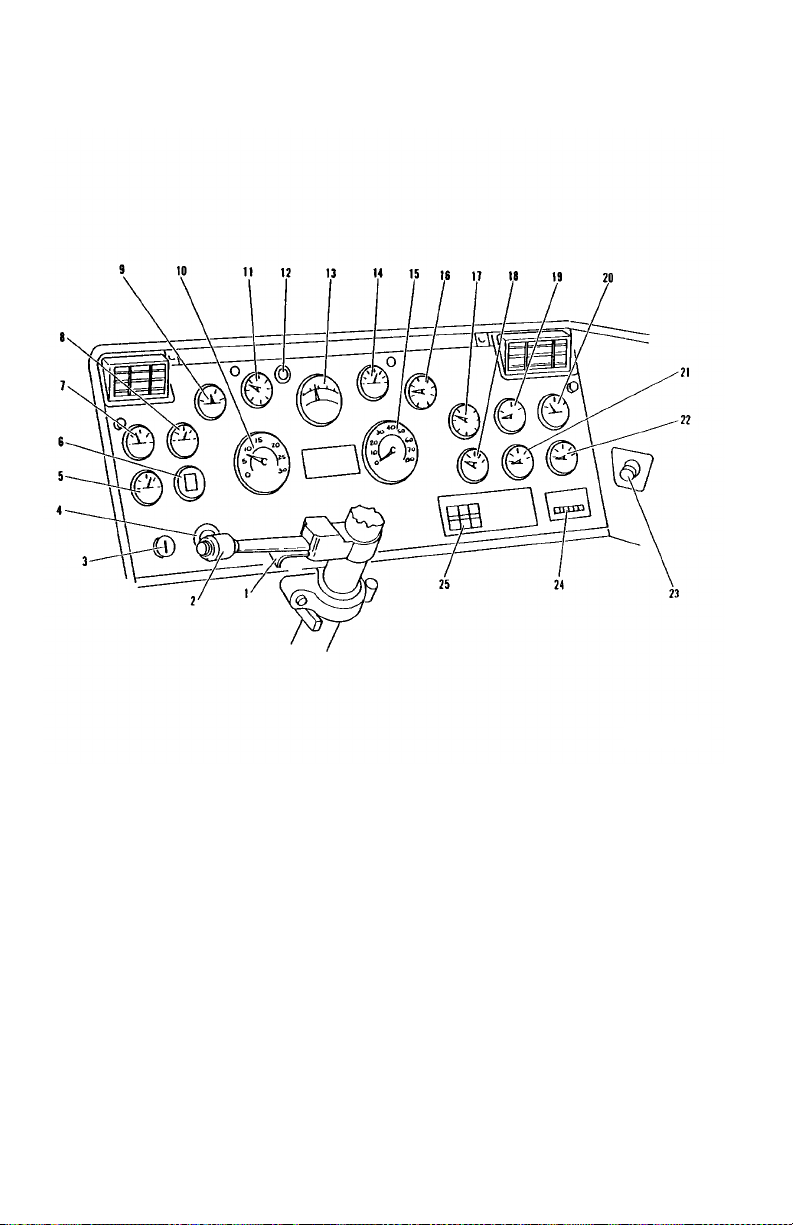
Typical COE Instruments and Controls
02973
LEFT SIDE
1. Hazard Flasher 14. Water Temperature
2. Turn Signal 15. Speedometer
3. Ignition Switch 16. Air Pressure
4. Start Button 17. Air Pressure
5. Manifold Pressure 18. Transmission Temperature
6. Air Cleaner Restriction G auge 19. Fuel Gauge
7. Ammeter 20. Clock
8. Voltmeter 21. Front Driver T em perature
9. Engine Oil Temperature 22. Rear Driver Temperature
10. Tachometer 23. Lighter
1 1. Oil Pressure 24. Trip Odometer
12. ABS Warning Lamp 25. Shift Pattern Decal (if used)
13. Pyrometer
PB1317 (CAT. NO. 5229 ) —18— 22-01510 (R12/01)
COE
PART 4: CONTROLS AND DISPLAYS
02974
RIGHT SIDE
1. Air Suspension Switch 13. Engine Fan
2. 5th Wheel Lock 14. Headlamps
3. Lockout Differential Switch 15. Ether Switch
4. Reset Circuit Breakers 16. Trail er Brake Hand Valve
5. Retarder Switch 17. Cab Air Selector
6. Loading Lamp 18. Cab Heat Control
7. Fuel Tank Selector L/R 19. Cab Ve nti lation
8. Light Toggle Switch 20. Cab A/C Control
9. Spot Light 21. Parking Brake Valve
10. Engine Brake 22. Trailer Air Supply
1 1. Mirror Heat 23. Right Hand Air Window
12. Clearance Lamps 24. Windshield Washer / Wiper
PB1317 (CAT. NO. 5229 ) —19— 22-01510 (R12/01)
PART 4: CONTROLS AND DISPLAYS
Steering Column-Mounted Controls
Turn Signal and Indicator Lights
02882
Model 379 vehicles built on
or after 5/1/98 with SRS
Your turn signal lever is mounted on the left side of the steering column below the steering wheel. Green directional indicator lights
appear on the instrument panel.
NOTE: The ignition key must be turned to ON for the signal/
switch to operate.
To operate the signal, move the lever in the direct i on of the turn.
02882A
W ARNI NG! Af t er yo u c ompl et e a tu rn , s hut the sy stem of f
by returning the lever to the “O FF” (center) positi on. The
switch's lever action is NOT self-canceling. Failure to shut
off a turn signal could confuse other drivers and res ul t in
an injury accident. An indicator light in the instrument
panel will flash until the turn signal is turned off.
PB1317 (CAT. NO. 5229 ) —20— 22-01510 (R12/01)

PART 4: CONTROLS AND DISPLAYS
Hazard Flasher
02883
or after 5/1/98 with SRS
The four-way Hazard Flasher switch is on the turn signal body, just
below the turn signal lever. It will operate with the key switch in the on
or off position. Use your hazard flasher whenever you are off the
road or on the side of the road, or in a potentially hazardous situation.
Pull it out to activate the system. All turn si gnals will flash at once. To
turn it off, move the turn signal lever up or down. Of course, in normal
stopping in traffic, such as at a stop light, you do not use your flashers.
WARNING!
time you have to stop off the road or on the side of the
road, day or night. A hard-to-see vehicle can result in an
injury accident. Another vehicle could run into you if you
do not set your flashers. Always move the vehicle a safe
distance off the road when stalled or stopped for repairs.
Use your Hazard Flasher Warning System any
02883A
Model 379 vehicles built on
A
disabled vehicle can be dangerous for you and others.
•
The hot exhaust system could ignite dry grass, spilled
fuel, or other substances. Do not park or operate your
vehicle where the exhaust system could contact dry
grass, brush, spilled fuel, or any other material that
coul d cause a fire.
Air Horn
Your Peterbilt has an air horn in ad dition to an e lectric horn. Control
the air horn by pulling on the lanyard extending from the overhead
header panel.
PB1317 (CAT. NO. 5229 ) —21— 22-01510 (R12/01)
PART 4: CONTROLS AND DISPLAYS
High Beam Headlights
02884
02884A
Model 379 vehicles built on
or after 5/1/98 with SRS
All Pe te rbilt vehicles c om e equipped with a combination t urn signal and
high beam/low beam s witch. To switch your headlights lower or higher
• For Model 379 vehicles built on or after 5/1/98 with SRS: Gently
pull the turn signal lever up, towards the steering wheel, until you
hear the switch “click” and the beam changes.
• For all other vehicles: Push and release the button on the end of
the turn signal lever
Electric Horn
Your Peterbilt has an ele ctric horn. To sound the horn, press on th e
button or bar in the center of the steering wheel.
02886
27884
Model 379 vehicles built on
or after 5/1/98 with SRS
PB1317 (CAT. NO. 5229 ) —22— 22-01510 (R12/01)
PART 4: CONTROLS AND DISPLAYS
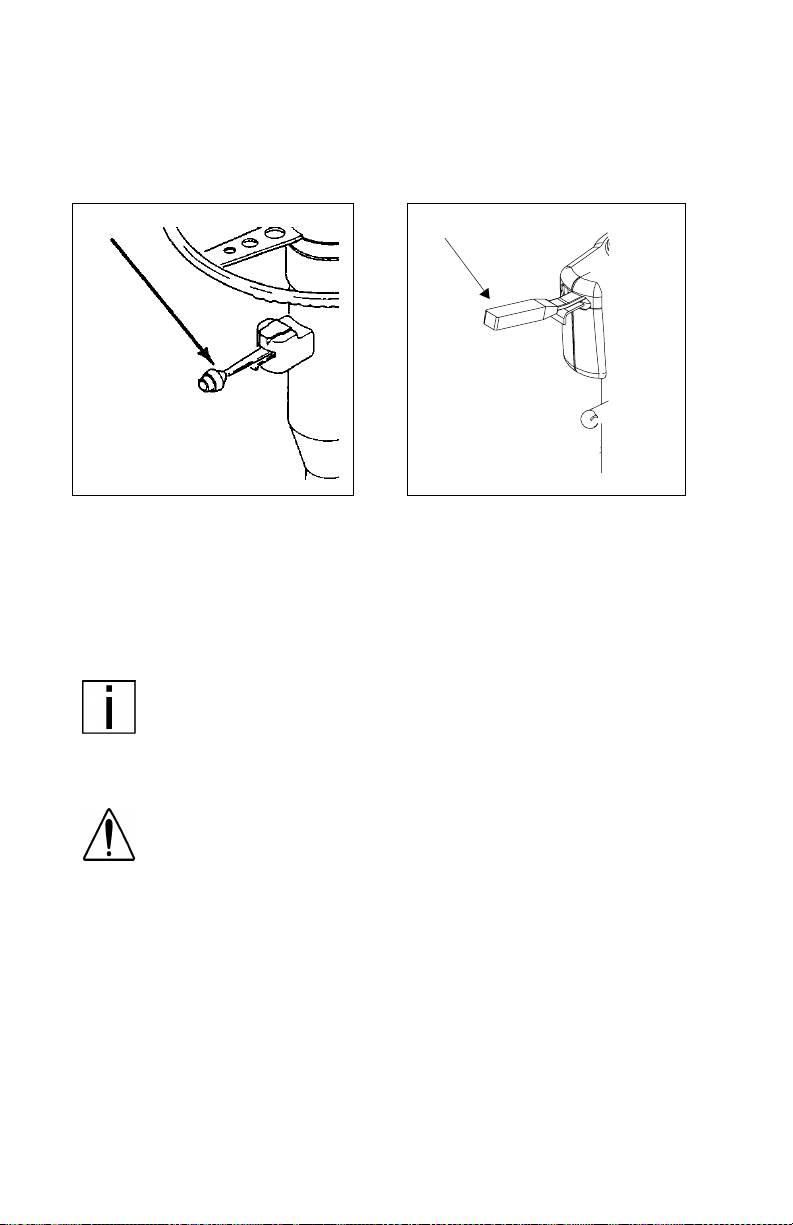
Trailer Brake Hand Valve
02975
02975A
Model 379 vehicles built on or after 5/1/98 with SRS
This hand valve provides air pressure t o a pply t he tr ailer brak es only.
It operates independently of the foot treadle valve.
To operate the trailer brake hand valve: Pull down on the lever
under the ri ght sid e of the st eeri ng whee l or on th e dash (C OE model s).
W ARNING! Grabbing th e trailer hand brake lever instea d
of the BrakeSaver lever could lead to an accident. If you
have the se l evers, they may be clos e to gether on your
steering wheel column. Be sure you get the one you
want. T he BrakeSaver lev er is bent, while the trailer p arking brake le ver is straight (see
Brake Safety and Emergency” for more complete information on
See “
page 36
).
when and how to use your trailer brake. Or see the Index, under Brake
NOTE: The trailer brake is not to be used as the main
means of braking. T o use this brake frequently instead of
using the foot brake will wear out the trailer brake sooner.
PB1317 (CAT. NO. 5229 ) —23— 22-01510 (R12/01)
.”
PART 4: CONTROLS AND DISPLAYS
WARNING! It is dange rous to use air-a ppl ied trailer
brakes for parking or holding a vehicl e. Air system pressure can bleed d o wn an d release the brakes. You could
have a vehicl e roll-away result ing in an accident. You or
others could be badly injured. Always apply the parking
brakes for parking or holding your vehicl e on grade.
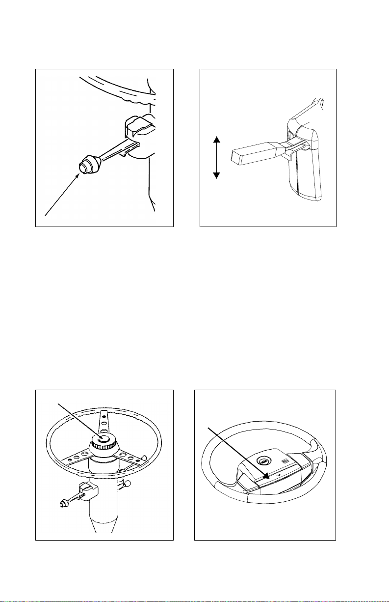
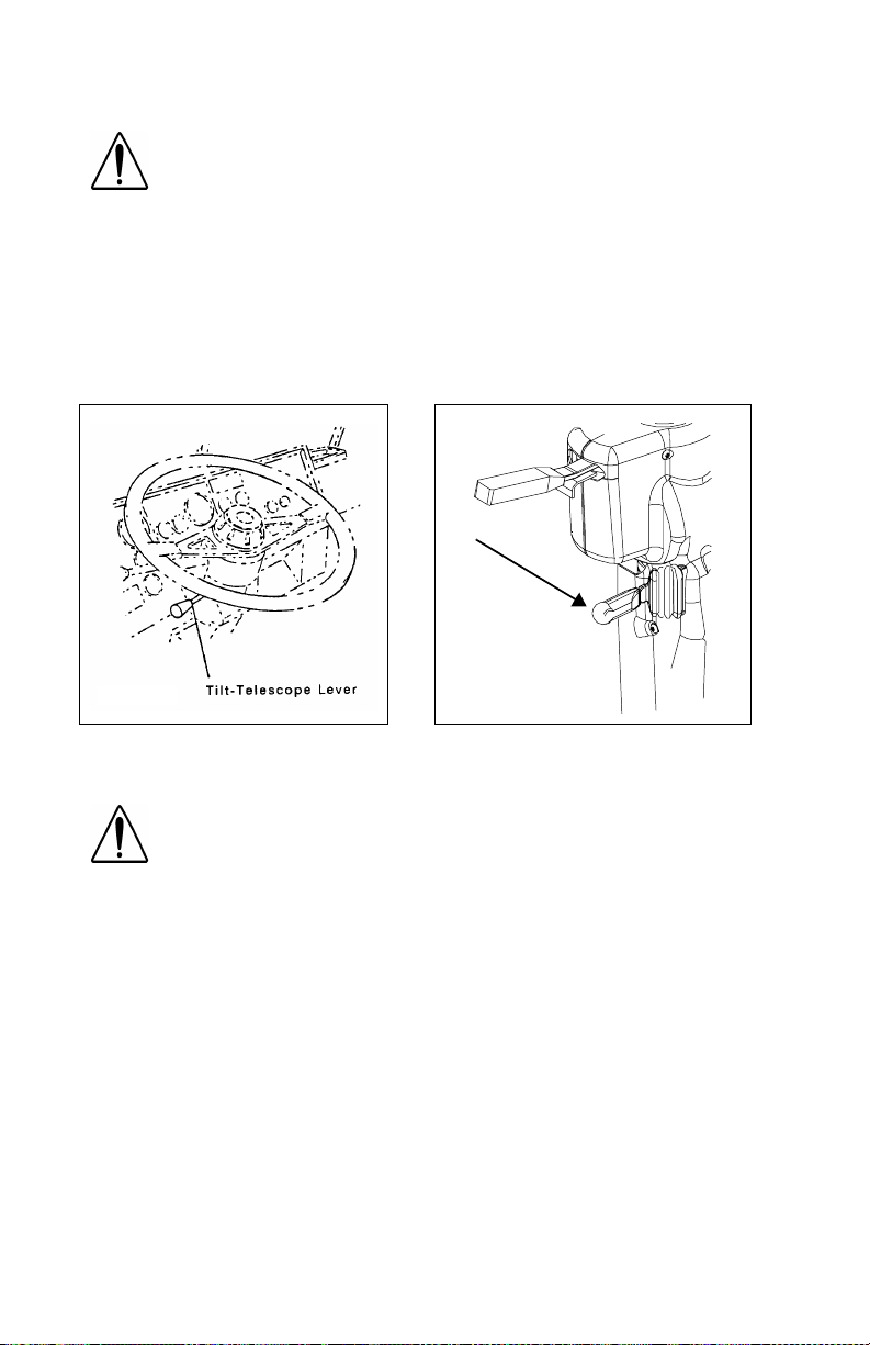
Tilt- Telescoping Steering Column
The tilting feature of the steering wheel allows forward and rearward
movement of the wheel . T he t elescopi ng f eature al lows y ou to m ove
the wheel up and down.
02976
02976A
Model 379 vehicles built on
or after 5/1/98 with SRS
WARNING! Adjustin g the Tilt-Telescoping Steering
Wheel while the vehicle is in motion could cause loss of
control. You wouldn’t be able to steer properly and
could have an accident. Make all adjustments to the
steering mechanism while the vehicle is stopped.
• Model 379 vehicles
To tilt the wheel: Push the lever away from yourself. Move the
steering wheel to the desired angle, then release the lever to lock.
To raise or lower the wheel: Pull the lever towards y ourself. Push
or pull the wh eel to the desi red he ight , th en rel ease t he lever to lo ck.
• All other models
To tilt the wheel : Pull the lever towards yourself. Move the steering wheel to the desired angle, then release the lever to lock.
To raise or lower the wheel: Push the lever away from yours el f .
Push or pul l the wheel to the des i red height, then re l ease the lever
to lock.
PB1317 (CAT. NO. 5229 ) —24— 22-01510 (R12/01)

PART 4: CONTROLS AND DISPLAYS
Dash-Mounted Features
Keys and Locks
Conventional Models: The same key fits your ignition, doors, and
sleeper luggage compartment.
COE Models: The same key operates the ignition and opens the
doors and the glove box.
Frame-mounted tool box locks and locking fue l tank caps each have
individual keys.
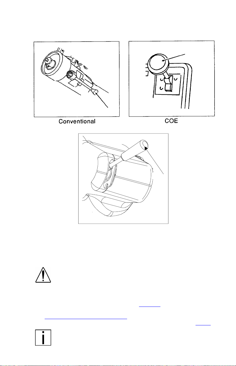
Ignition Switch
Your ignition switch has three (COE) or four (conventional) positions:
OFF
ACC ONLY
IGN & ACC
START
02977A
ACC (Accessory): With your key in this position you can play the
radio or use other accessories, but your engine
won’t start.
OFF: In this position all systems are off, and you can
remove yo ur key.
IGN & ACC: This position allows you to turn on the engine
and all accessory power.
START: Starter activation to start engine (conventional
models only).
PB1317 (CAT. NO. 5229 ) —25— 22-01510 (R12/01)
PART 4: CONTROLS AND DISPLAYS
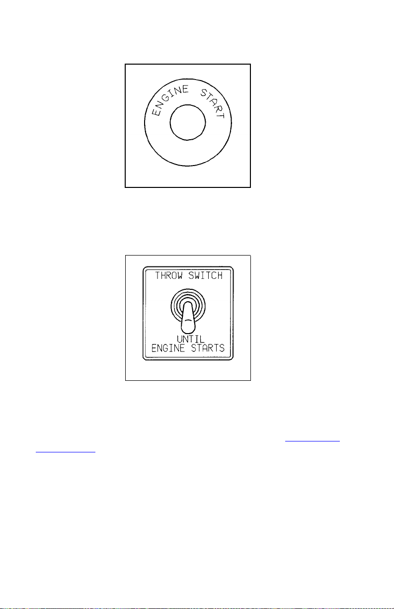
Starter Button
02887
On COE models: with the key switch in the IGN & ACC position, push
the starter button; this will engage the starter motor and crank the
engine.
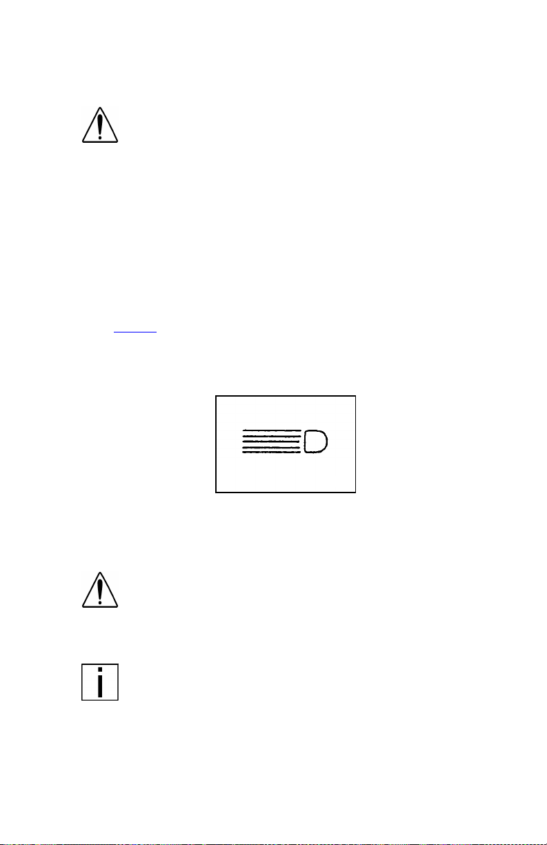
Manual Override for Engine Shutdown
02889
On vehicles with an engine shutdown, you will have to hold the manual throw switch in the UP position until normal engine pressures are
reached. If you have one of t hese systems, a label on the control
panel will say so.
For detailed starting procedures, see the Index, under St arting and
Operating 80.
PB1317 (CAT. NO. 5229 ) —26— 22-01510 (R12/01)
PART 4: CONTROLS AND DISPLAYS
Hand Throttle Control
WARNING! Do not use the hand throttle control as a
cruise control. It could cause an accident and you
could be seriously injured. In an emergency you m ight
not be able to unset it in time to save yourself and your
vehicle from an accident. Never try to control road
speed with your hand throttle control. Always push in
the hand throttle before driving the vehicle.
If you have a hand throttle, in conventional cabs it is usually located to
the left of the driver’s seat, mounted on the floor. In COEs it is un der
the lefthand dash. It can be especially helpful in cold weather to keep
your engine running at above idle speed when you leave the vehicle
briefly.
For more information on idling your engine safely, see the Index,
under Engine
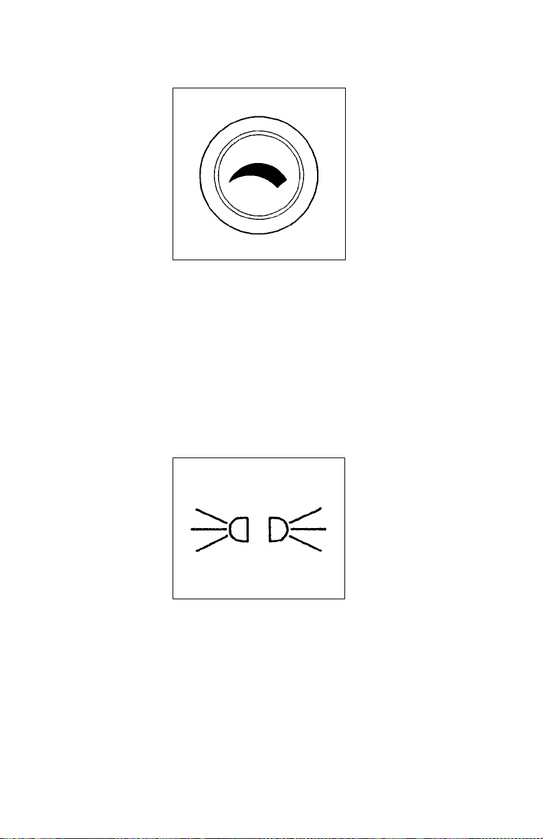
Headlights
.
02890
The headlights are controlled by the control panel switch showing this
symbol. When the headlights are ON, the dash lights, side, and tail
lamps are also on.
WARNING! Do not use daytime running lights (DRL)
during periods of darkness or reduced visibility. Do not
use DRL as a substitute for headlights or other lights
during ope rat i on s tha t re qu ire l ig ht i ng of your vehicle.
Doing so could lead to an injury accident
NOTE: On vehicles equipped with daytime running lights
(DRL), the high-beam headlamps go on automatically at
reduced brightness if the engine is running and the headlamp switch is turned off. The daytime running lights are
turned off automatically while the parking brake is engaged.
If the headlamp switch is turned on, the DRL system is overridden & headlamps operate normally.
PB1317 (CAT. NO. 5229 ) —27— 22-01510 (R12/01)
PART 4: CONTROLS AND DISPLAYS
Panel Light Knob
02891
The Panel Light Knob lets you vary the brightness of your instrument
panel lights.
To Operate Your Panel Light Knob:
1. Turn on either the headlights, clearance lights, or fog / driving
lights.
2. To brighten the instrument panel lights, turn the knob clockwise (to
the right).
3. To dim the instrument lights or to turn them off, turn the knob counterclockwise (to the left).
ID and Clearance Lights Switch
02892
These are the ambe r lights on top o f your cab, the lights on the front
and sides of the trailer, and the red lights on the rear of a truck or
trailer. They are controlled by the control panel switch labelled CL
LPS.
PB1317 (CAT. NO. 5229 ) —28— 22-01510 (R12/01)
Loading...