


 Loading...
Quick Table of Contents |
|
Introduction ..................................................................................................... |
1 |
Electric Power System.................................................................................... |
7 |
Heating and Air Conditioning System......................................................... |
25 |
Troubleshooting............................................................................................ |
41 |

PART 1: INTRODUCTION |
Safety Signals |
|
|
PART 1: INTRODUCTION
Safety Signals
A number of alerting messages are in this manual. Please read and follow them. They are there for your protection and information. These messages can help you avoid injury to yourself and your passengers, and help prevent costly damage to the vehicle.
Key symbols and “signal words” are used to indicate what kind of message is going to follow. Pay special attention to instructions prefaced by symbols and signal words “WARNING,” “CAUTION,” or “NOTE.” Please do not ignore any of these alerts.
 WARNING:
When you see this symbol and word, the message that follows is especially vital. This signals something that can cause injury or even death. This message will tell you what the hazard is, what can happen if you don’t heed the warning, and how to avoid it. For example:
WARNING! Do not carry additional fuel containers in your vehicle. Fuel containers, either Figure -4 full or empty, may leak, explode, and cause or feed a fire. Do not carry extra fuel containers.
Even empty ones are dangerous.
 CAUTION:
This symbol and word signals something that could damage your vehicle. For example:
CAUTION: Continuing to operate your vehicle with insufficient oil pressure will cause serious engine damage.
R(09/07) |
Y53-6017 |
– 1 – |

Safety Signals |
PART 1: INTRODUCTION |
|
|
NOTE:
i
i
Gives you information we feel you would like to have. It could have to do with care of your vehicle or with driving more efficiently. For example:
NOTE: Pumping the accelerator will not assist in starting the engine.
Please take the time to read these messages when you see them, and remember:
WARNING!
Something that could cause an injury or even death.
CAUTION:
Something that could cause damage to your vehicle.
NOTE:
Useful information.
– 2 – |
Y53-6017 |
R(09/07) |
PART 1: INTRODUCTION |
The Peterbilt ComfortClass™ System |
|
|
The Peterbilt ComfortClass™ System
This system utilizes a sleeper air conditioning system and diesel fuel-powered sleeper heater that are compliant with anti-idling requirements. The sleeper air conditioning system provides up to 10 hours of engine-off cooling in typical conditions*. The air conditioning system recharges as the vehicle is driven or by shore power and requires approximately 4-6 hours of recharging depending upon outside conditions. The cold air for the air conditioning system comes from a Storage Cooler that is located behind the sleeper. It stores the system’s cooling capacity by freezing water. As the system is used, the ice melts back into water and needs to be recharged (frozen) again by the Air Conditioning Charge Unit.
The system is powered by an energy-efficient ComfortClass System Battery Box that includes four deep-cycle AGM batteries and is outfitted with 2000 watt, 12 VDC/120 VAC inverter. The system includes a 20 amp shore power capability with a 25-foot shore power cable and includes ComfortClass System battery charging capability while on shore power.
The system has an enhanced charge/start capability that includes two 1000 CCA dedicated Starter Batteries in the
starter battery box, a starter battery charger and a 185A alternator with remote voltage regulator located in the ComfortClass System Battery Box. The voltage regulator is optimized and pre-programmed with a specific charge profile for optimal charging of the deep-cycle batteries that increases the deep-cycle battery life.
An enhanced insulation package includes upgraded sleeper in-wall insulation. Interior features include the following:
•Floor insulation,
•A cab dash-mounted A/C charge enable switch,
•Two 120 VAC, GFCI (ground fault circuit interruption) duplex outlets in passenger side closet and under driver side bunk,
•A dedicated sleeper control panel with diagnostic feedback, via “blink” codes (status of HVAC modes, inverter modes, alerts, etc.),
•Sleeper fresh or recirculated air intake, and
•A premium-grade dust and pollen filter readily accessible under sleeper bunk.
* Overall performance may vary depending on conditions described on page 33.
R(09/07) |
Y53-6017 |
– 3 – |
The Peterbilt ComfortClass™ System |
PART 1: INTRODUCTION |
|
|
System features include:
•Engine-off sleeper heating, cooling, and 120-Volt AC power.
•No engine noise or vibration.
•Decrease in overall fuel consumption.
|
NOTE: This system is NOT designed to cool a |
|
i |
||
hot sleeper. Use the vehicle’s air conditioner to |
||
|
pre-cool the sleeper to at least 75°F prior to turn- |
|
|
||
|
ing on the ComfortClass System air conditioner. |
|
|
The system can then be used to maintain that |
|
|
temperature. |
|
NOTE: The system is designed to maintain the |
|
i |
||
interior sleeper temperature around 75°F for a |
||
period of up to 10 hours*, based on maximum |
||
|
||
|
outside temperature of 95°F, a relative humidity |
|
|
of 50%, and with the sleeper not in direct sun- |
|
|
light. The sleeper environment must be |
|
|
pre-cooled to 75°F by the air conditioner prior to |
|
|
use of the system. The system is NOT designed |
|
|
to maintain sleeper temperatures under |
|
|
extremes of heat or direct sunlight. You may |
|
|
need to supplement the ComfortClass System by |
|
|
operating the vehicle’s air conditioner if the Com- |
|
|
fortClass System is unable to maintain the |
|
|
desired temperature level. |
*Overall performance may vary depending on conditions described on page 33.
This Operator’s Manual contains useful information for the safe and efficient operation of your ComfortClass System.
All information contained in this manual is based on the latest production information available at the time of publication. Peterbilt Motors reserves the right to make changes at any time without notice.
– 4 – |
Y53-6017 |
R(09/07) |

PART 1: INTRODUCTION |
The Peterbilt ComfortClass™ System |
|
|
Location of Components
Air Handler
(Under Lower Bunk)
Fuel-Fired Heater (in passenger’s side toolbox)
High Output Alternator
Starter Batteries
Disconnect Switch
Starter Batteries |
Circuit Breaker Box |
Storage Cooler |
|
(located in driver’s side toolbox) |
(Behind Sleeper) |
||
|
Enhanced Insulation
Air Conditioning
Charge Unit
ComfortClass System
Battery Disconnect Switch


 Shore Power Connector
ComfortClass System
Battery Box
ComfortClass System Batteries
PB00001
R(09/07) |
Y53-6017 |
– 5 – |
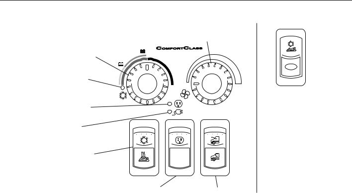
The Peterbilt ComfortClass™ System
Location of Components
Temperature Control Dial (Pages 29 & 32)
Air Conditioner Pump ON Lamp (Green) (Page 26)
Inverter/Charger Lamp (Page 19)
Shore Power Lamp (120-Volt AC) (Page 19)
Air Conditioning/Heating Switch
(Pages 29 & 32)
Sleeper Control Panel |
Fan Control Dial |
(located in Sleeper) |
(Page 26) |
OFF
NORMAL
OFF/RESET
Inverter/Charger Switch Sleeper Fresh/Recirculation Air
(Page 18) Switch
(Page 27)
PART 1: INTRODUCTION
CHARGE
Charge/Enable Switch (located on cab dash) (Page 37)
PB00002
– 6 – |
Y53-6017 |
R(09/07) |
PART 2: ELECTRIC POWER SYSTEM |
Charging/Jump-Starting Instructions |
|
|
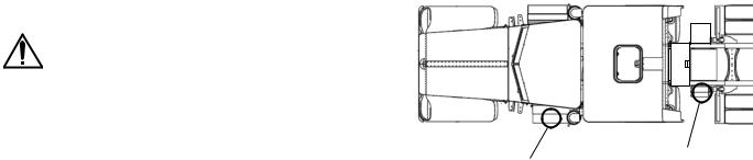
PART 2: ELECTRIC POWER SYSTEM
Charging/Jump-Starting Instructions
WARNING! The electrical charging system used for the ComfortClass System is different from normal charging systems. Failure to adhere to the proper charging or jump-starting procedures could lead to death or serious injury, damage to the Inverter/Charger or vehicle damage. Follow the Charging/Jump-Start- ing Instructions on page 10.
|
NOTE: The charging/jump-starting instructions |
|
i |
||
can also be found on the top of the ComfortClass |
||
|
System Battery Box cover. |
ComfortClass System
Starter Batteries |
Batteries |
|
|
|
PB00006A |
Vehicles equipped with the ComfortClass System have battery configurations that are different from traditional vehicles. These vehicles have a dedicated set of batteries in addition to the Starter Batteries. These batteries are referred to as the “ComfortClass System Batteries.” These batteries provide power to the vehicles’ electrical demands including on-board computers and the starting batteries. The starter is the only electrical device that does not depend on the ComfortClass System Batteries. The schematic on page 9 is provided to help illustrate the system.
R(09/07) |
Y53-6017 |
– 7 – |

Charging/Jump-Starting Instructions |
PART 2: ELECTRIC POWER SYSTEM |
|
|
NOTE: Do not attempt to jump-start the vehicle i without first reading the instructions on top of the ComfortClass System Battery Box cover. If you have a battery problem, it is best to contact an authorized repair facility or a reputable towing service. When you do, inform them of the charging instructions on page 10 and the wiring schematic on page 9. These instructions can also be found on the top of the ComfortClass System
Battery Box cover.
– 8 – |
Y53-6017 |
R(09/07) |
PART 2: ELECTRIC POWER SYSTEM |
Charging/Jump-Starting Instructions |
|
|
Wiring Schematic
R(09/07) |
Y53-6017 |
– 9 – |
Charging/Jump-Starting Instructions |
PART 2: ELECTRIC POWER SYSTEM |
|
|
The ComfortClass System Batteries are located in the ComfortClass System Battery Box behind the sleeper, on the driver’s side. They power all electrical systems on the vehicle EXCEPT the starter motor.
|
NOTE: Because the ComfortClass System Bat- |
|
i |
||
teries power the engine controls and starter |
||
|
relay, you may experience a no-crank condition if |
|
|
||
|
the ComfortClass System Battery voltage is |
|
|
below 9.5-Volt, even though the Starter Batteries |
|
|
are fully charged. |
|
|
NOTE: A DC/DC charger, also located below |
|
i |
||
the cab on the driver’s side, serves to isolate the |
||
|
starting batteries from the ComfortClass System |
|
|
Batteries and provides charge to the starting bat- |
|
|
teries to maintain them at a minimum of 12-Volt. |
|
|
NOTE: The DC/DC charger will only be acti- |
|
i |
||
vated when either the truck is running or the |
||
|
truck is attached to a shore power electrical sup- |
|
|
||
|
ply and the key is in the IGN or ON position. |
Charging/Jump-Starting Instructions
There may be occasions where the vehicle will crank but it will not start, even after charging the starting batteries and/or attempting to jump-start the vehicle using normal procedures found in the Operator’s Manual. You may also notice that the voltage meter on your dash is below 11 volts, interior lights are dimmed or not on, and the DC outlets have no power.
|
NOTE: The voltmeter only monitors the Comfort- |
|
i |
||
Class System Batteries, not the Starter Batteries. |
In such situations, the ComfortClass System System Battery voltage has dropped below 9.5 volts. It is necessary to charge the ComfortClass System System Batteries to above 11 volts (and ensure that the Starter Batteries are at 12 volts) in order to start the vehicle.
– 10 – |
Y53-6017 |
R(09/07) |
PART 2: ELECTRIC POWER SYSTEM |
Charging/Jump-Starting Instructions |
|
|
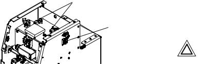
Charging Terminals
Shore Power
Connector
PB00032
The ComfortClass System Batteries are located in the driver’s side frame-mounted box located behind the sleeper. The batteries can be accessed by removing the cover plate and connecting a charger to the charging terminals. Turn the battery disconnect switch, on the side of the ComfortClass System Battery Box, to the “ON” position if you want to charge the batteries using the charging terminals. Charging these batteries can also be performed by using the shore power connection on the side of this box.
Please have your ComfortClass System inspected by an authorized dealer if your ComfortClass System Batteries continue to drop below 11 volts or if you are unable to start the vehicle after charging both the starter and the ComfortClass System Batteries.
Refer to “Battery Charging” and “Jump-Starting Vehicles” in the Peterbilt Operator’s Manual for additional battery charging and jump-starting procedures. Also, refer to the Troubleshooting Section on page 41 for more details.
CAUTION: Do not connect any accessories directly to the starting batteries. This could drain the batteries to a point where they can no longer start the engine.
R(09/07) |
Y53-6017 |
– 11 – |
Charging/Jump-Starting Instructions |
PART 2: ELECTRIC POWER SYSTEM |
|
|
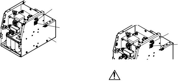
Disconnect Instructions
ComfortClass System Batteries Disconnect Switch (shown in the off position)
Shore Power
Connector
ComfortClass System
Battery Box
PB00004
Prior to servicing the vehicle, disconnect the electrical system as follows:
1.Turn air heater off and wait three minutes prior to turning the disconnect switches to the OFF position (steps 3 and 4 below). This gives three minutes for the heater to purge any fuel still in the heater and allows the unit to cool off.
2.Unplug shore power connection.
3.Turn Starter Battery disconnect to OFF position.
4.Turn ComfortClass System Battery disconnect located on ComfortClass System Battery Box (located on driver’s side, rear of sleeper) to OFF position.
Charging ComfortClass System Batteries using Shore Power
ComfortClass System
Batteries Disconnect
Switch
Shore Power
Connector
PB00005
WARNING! Electric Shock Hazard. 120-Volt AC power present. This can cause electrical shock or fire resulting in death, personal injury or property damage. Only a trained technician should work on the shore power system. Turn all battery disconnect switches to the OFF position and unplug the shore power electrical supply before servicing any part of the vehicle’s electrical system.
– 12 – |
Y53-6017 |
R(09/07) |
Loading...