


Rear Air Adjustment
FIELD
SERVICE
BULLETIN
A DIVISION OF
ilqN
Date:
File
Group:
ATTENTION:
ServiceManager
Distribution
Copy:
/Dealer Principal
lWarranly Manager
/Parls Manager
/Sales Manager
Setting/Adiusting
RearAxle Angles:
Proprietary
RearAir
Susoensions Except FLEXA|TTM
This
bulletin is
applicable to vehicles
equipped with
proprietary
rear
air suspensions
exceot FLEX AirrM
suspensions;
i.e., Air Leaf,
Low Air Leaf, Low
Low Air Leaf, and Air
Trac
suspensions. lt
provides
a
procedure
to set ride height
and adjust rear
axle angles
on those vehicles.
.
This
bulletin
supersedes the information
on
"Measuring
Pinion Angle"
and
"Setting
Air
Spring Height
(Ride
Height)" in
Section 6,
"Rear
Suspension" of the master mainte-
nance manual
for vehicles
equipped
as described
above. The manual will
be
updated in
the near future
to reflect the
changes made
by this bulletin.
The
ride height
of
proprietary
rear
air suspensions
is set
at the
factory.
The specifications
used
are designed to
provide
the vehicle
with the best
possible
axle travel
and
ride
charac-
teristics.
There
are occasions when
a customer will
reset or
adjust the ride height
after a
vehicle has
been
put
in
service. Peterbilt recommends
against this for
the
following
reasons:
'
Changing the ride height results
in
a change in rear
axle driveline
angles.
This
situa-
tion can lead
to driveline vibration.
'
Changing
the
ride
height may
have
a detrimental effect
on axle travel, and may
also
result in
complaints
of
rough
ride.
Peterbilt
recommends
that
customers be
encouraged
to avoid these
potential problems
by maintaining
the ride height
at the factory
setting.
When necessary
the
rear
axle
angle(s)
should be returned
to the original factory
specification. A new
adjustment
pro-
cedure that removes
the
effect of
frame
rake variation
on
pinion
angles was implemented
on 6/26199
(Denton)
and 814199
(Madison).
Using this method
permits
setting
rear
driver
and interaxle
driveshaft angles
to
provide
the best
possible
axle travel
and U-joint can-
cellation as well
as keep torsional
acceleration
within
specifications. The
procedure
and
supporting information
is
contained in
this bulletin. The
special ride height
tool required
for
this
procedure
is available from
PACCAR Parts
(see
Parts
Notes below).
Parts
Notes
The
parts
referred
to in
this bulletin are listed
below
and available from PACCAR
Parts
using normal
ordering
procedure.
April7,2004
03 Section:
Rear
Suspension
Part Number
Description
+z-uuz]v-uu1
Kroe
nergnr roor (gauge)
J3-U6 /6U-0U1
,
-002,
-003, -004
Axle
shim
(for
Low Air
Leaf
suspensions on/after 415104)
Pro
3600 Anglemaster
Inclinometer (available
at
http://www.
penntoolco.
com/cataloq/products/697.
cfm)
PS803035
F.S.B.
# 3-00R
Page
1 of 42
Setting and Adjusting Ride
Height and Rear Axle Angles
WARNING!
This
procedure
requires
seruicing
the
vehicle with
the trans-
mission in neutral
and the
parking
brakes
released. The vehicle must
be
parked
on a completely
flaUlevel
surface with
both
front wheels
chocked
on both
sides.
Failure
to adequately
chock the
wheels may lead
to the
vehicle rolling into
someone/something,
causing an accident and
possi-
ble serious
personal
injury
and/or equipment
damage.
NOTE: Suitable wheel
chocks are at a minimum
an
18-inch
(46
cm)
long 4x4
Follow
this
procedure
to set ride height
and adjust
rear
axle angles
(pinion
angles).
1.
Ensure that
the
following
tools are available:
.
Ride height tool
(gauge)
.
Pro-3600
or
Pro-360 Anglemaster
(inclinometer)
.
Adapter for Anglemaster
2.
Drive the vehicle
onto a
flaUlevel
surface. Back
straight out for the
length
of the
vehi-
cle and slowly
drive back onto the flaUlevel
surface. Gently roll to a stop.
Place
the
transmission in neutral
and set the
parking
brakes.
3. Chock the front wheels
on both sides.
4. Release
the
parking
brakes.
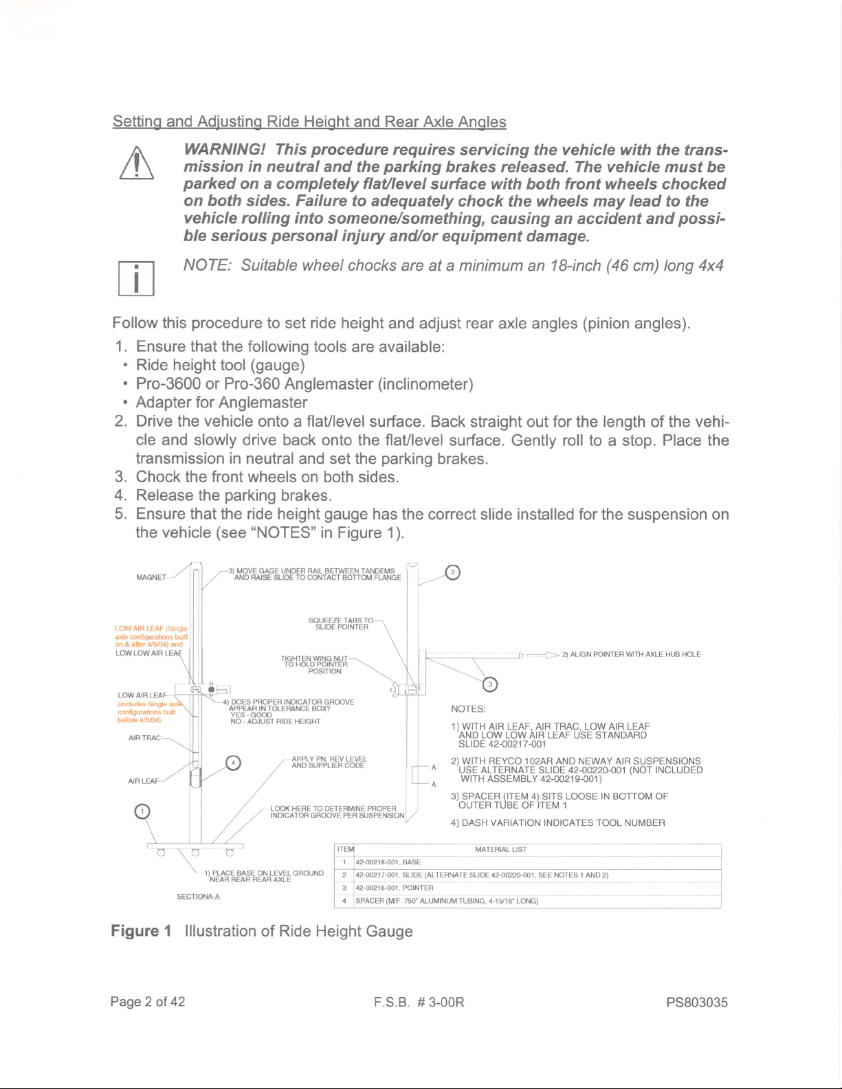
5.
Ensure
that the ride height
gauge
has
the correct slide installed for
the suspension
on
the vehicle
(see
"NOTES"
in Figure
1).
-3t MOVE GAGE UNDER RAIL BETWEEN TANDEMS
,/
ANO
RAISE SLIDE TO CONTACT BOTTOi' FI-ANGE
"tr-t@
LOW AIR LEAF
(Srngle
axle conirgurations burll
on & atter 4/904) and
SOUEEZ E TABS TO
SLIDE POINTER
LOWLOWAIR
----->
2) AL|GN POTNTER W|TH AXLE HUB HOLE
Lol^/ AIR LEAF
(includes
Srngle
conliguralons built
belore 4/5/04)
TIGHTEN WING NUT
TO HOLD POINTER
POSITION
l
DOES PROPER INDICATOR
GROOVE
APPEAR IN TOLEMNCE AOX?
YES.
G@D
NO
-
ADJUST BIDE HEIGHT
APPLY PN, REV LEVEL
AND
SUPPLIER CODE
LooK HERE TO
DETERMINE PROPER
INDICATOR GROOVE PER SI.JSPENSION
o
1) PLACE BASE ON LEVEL GROUNO
NEAR REAR REAR AXLE
Figure
1 lllustration
of
Ride Height
Gauge
MATERIAL LIST
1 ,42d218-001.
BASE
2 42{n'217
-0o1,SLIDE
(ALTERMTE
SLTDE 42-00220-001, SEE NOTES 1 AND 2)
3
142{0216{01,
POINTER
n
lseecen
lwr
.zso' ALuMTNUM TUBTNG, 4-1l,16'
LoNG)
NOTES:
1) WITH
AIR LEAF, AIR TRAC, LOW AIR LEAF
AND LOW LOW AIR LEAF USE STANDARD
sLIDE
42-0021
7-001
2) WITH
REYCO 1O2AR AND NEWAY AIR SUSPENSIONS
-USE
ALTERNATE SLIDE 42.OO22O.OO1
(NOT
INCLUDED
wrTH
ASSEMBLY
42-00219-001
)
3) SPACER
(ITEM
4)
SITS
LOOSE IN
BOTTOM OF
OUTER TUBE OF ITEM 1
4) DASH VARIATION
INDICATES TOOL NUMBER
U\
Page2
of
42
F.S.B. # 3-00R PS803035

6.
7.
Place
the
ride height
gauge
near
the
rearmost
axle such that
the base
is
on
level
ground
(see
Figure
1 and Figure 2
).
Align the
pointer
of the
gauge
with the axle hub hole
(see
Figure 2).
a. Squeeze the tabs to slide
the
pointer
into
proper position.
b. Tighten the wing nut
to
hold
the
pointer
in that
position.
ALIGN POINTER WITH AXLE HUB HOLE
,-
-->
Figure
2 lllustration
of
Aligning The
Pointer of a Ride Height
Gauge
PS803035
F.S.B.
# 3-00R Page
3 of
42
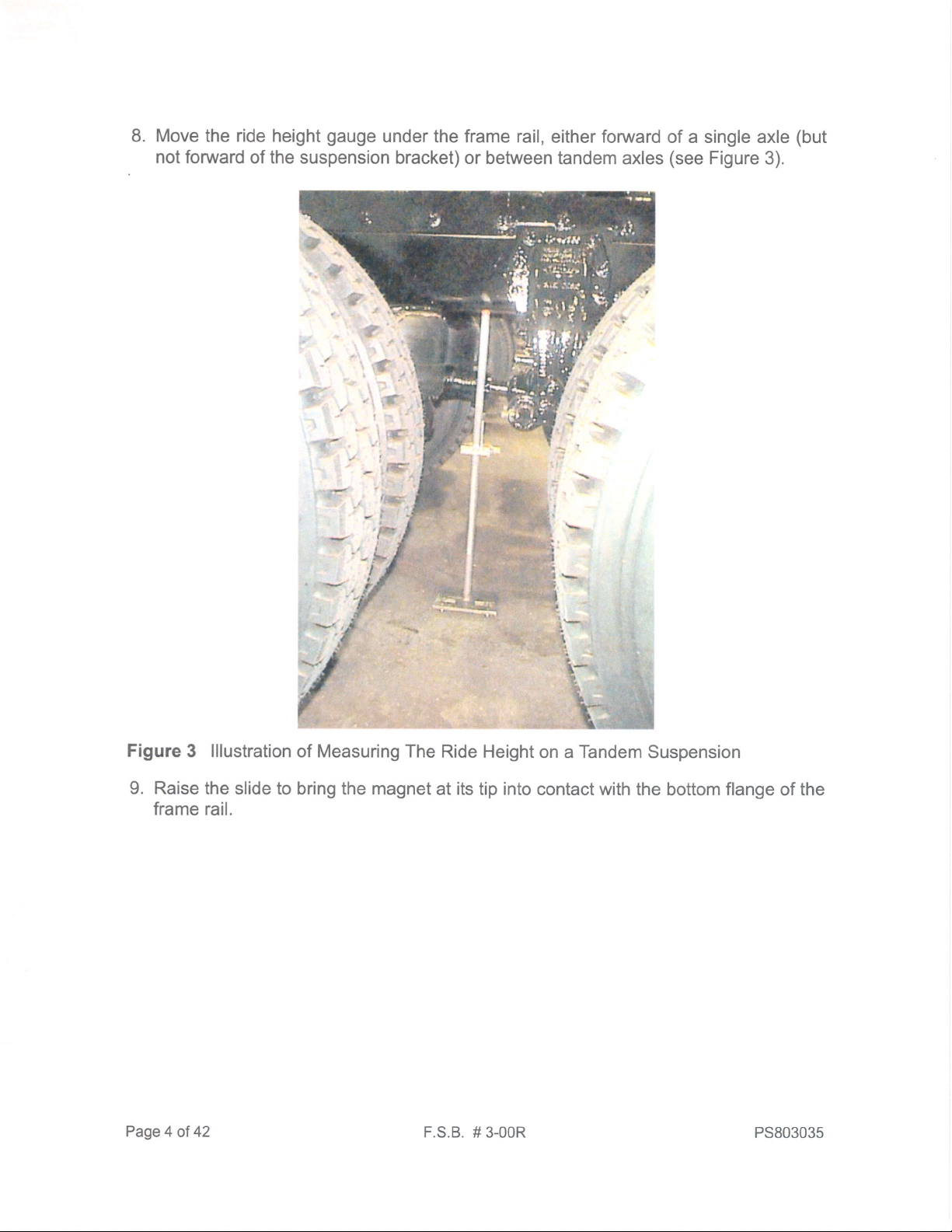
8. Move the ride height
gauge
under the frame rail,
either
forward
of a single axle
(but
not forward
of the suspension
bracket) or between
tandem axles
(see
Figure 3).
Figure
3
lllustration
of Measuring The
Ride Height
on a
Tandem
Suspension
9. Raise the slide
to bring the magnet
at
its
tip
into
contact with
the bottom
flange
of the
frame rail.
Page
4 ot 42
F.S.B.
# 3-00R
PS803035
,\
,/
.)
/
MOVEGAGEUNDERRAILBETWEENTANDEMS
MAGNET
,/
AND RAISE SLIDE TO
COMTACT BOTTOM FLANGE
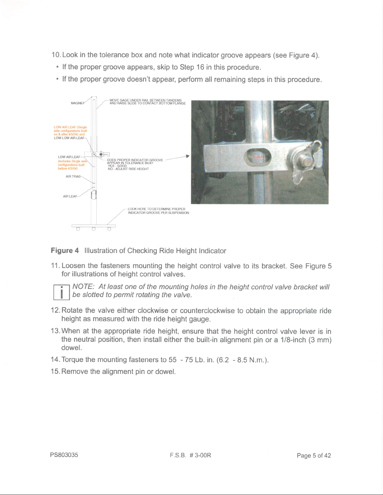
10. Look in
the tolerance box
and
note
what indicator
groove
appears
(see
Figure 4).
.
lf
the
proper
groove
appears, skip to
Step
16
in this
procedure.
.
lf
the
proper
groove
doesn't appear,
perform
all remaining
steps in this
procedure.
LOW AIF
LEAF
(Srngle
axle conliguraions buill
on & after 4/5/G) and
LOWLOWAIR
LOW AIR LEAF
(nrcludes
Single a)
configuralons burll
belore 4/Y04)
DOES PROPER INOICATOR
GROOVE
APPEAR IN TOLEMNCE BOX?
YES.
G@D
NO.
ADJUST RIDE HEIGHT
";1\
.|
f
orr/il
LOOK HERE TO OETERMINE PROPER
INOICATOR
GROOVE PER SUSPENSIoi']
Figure 4 lllustration
of
Checking Ride Height lndicator
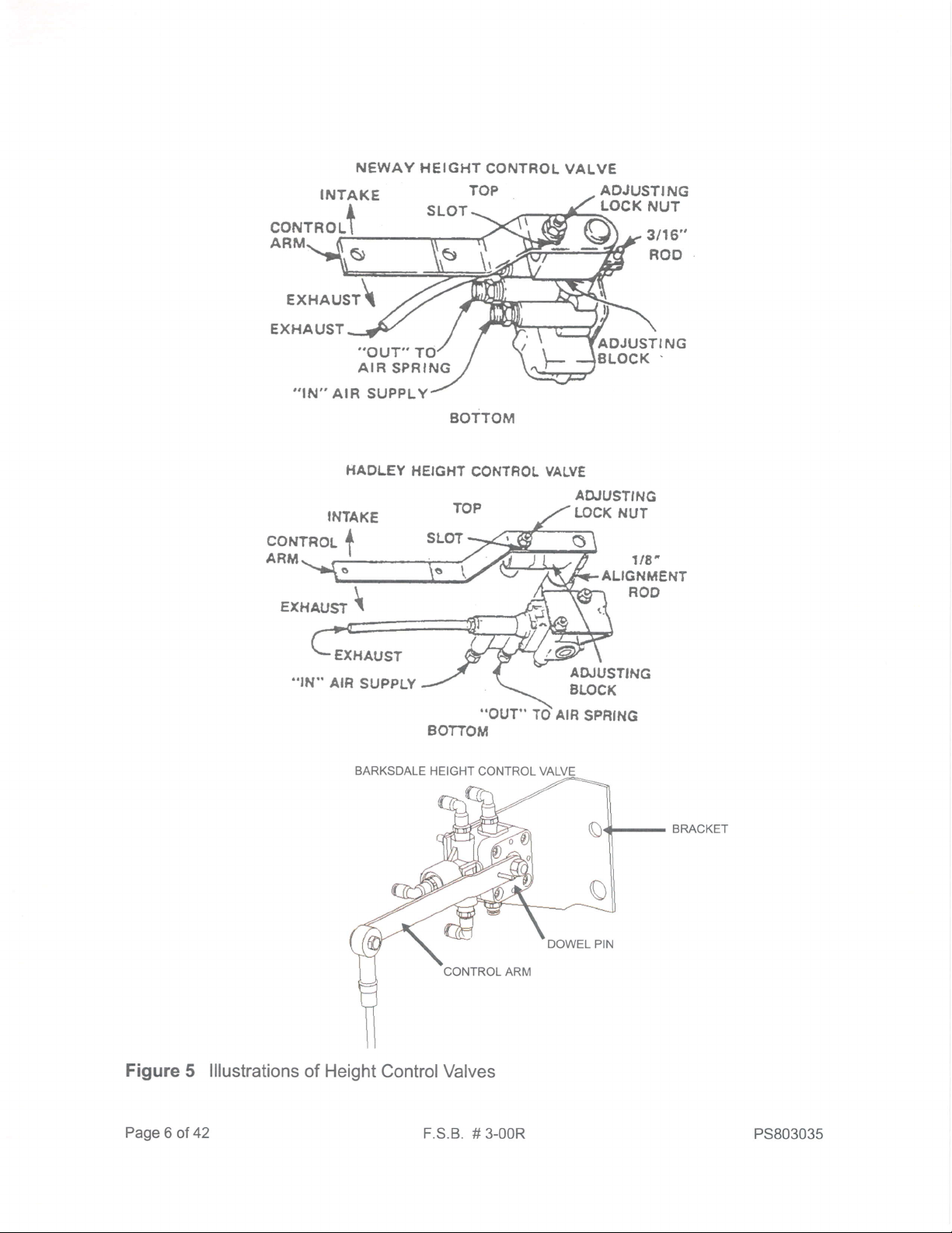
11.Loosen
the fasteners
mounting
the height control valve
to its bracket.
See
Figure5
for
illustrations
of
height
control valves.
NOTE:
At least
one of the mounting holes
in the height
control
valve
bracket will
be slotted
to
permit
rotating
the valve.
12.Rotate
the valve
either clockwise
or counterclockwise
to obtain the appropriate ride
height
as measured
with the ride height
gauge.
13.When
at the
appropriate ride height,
ensure that
the height control valve lever is in
the neutral
position,
then install either
the built-in
alignment
pin
or a 1/8-inch
(3
mm)
dowel.
14.Torque
the mounting
fasteners to
55
-
75 Lb. in.
(6.2
-
8.5 N.m.).
15. Remove
the alignment
pin
or dowel.
PS803035
F.S.B.
# 3-00R
Page
5 of 42
NEWAY
HEIGHT
CONTROL
VALVE
INTAKE
CONTROLT
ADJUSTING
LOCK
NUT
3t16"
ROO
ADJUSTING
LOCK
.
ARM
EXHAUST\
EXHAUST
.,OUT"
T
AIR
SPRING
,,IN''
AIR SUPPLY
BOTTOM
HADLEY
HEIGXT
CONTROL
VALVE
AIUUSTING
LOCK NUT
INTAKE
EXHAUST
\
€XHAUST
..IN"
AIR
SUPPLY
Figure
5 lllustrations
of Height ControlValves
Page
6 of
42
F.S.B.
# 3-00R
7tE',
ALIGNMENT
ROD
80770M
PS803035

[Tl
NOTE:
Contact PACCAR
Pafts Research
(1-800-477-0251)
to obtain rear
LU
axle
angle
information
for newer
vehicles whose
records
are
not
yet
in
ECAT.
16.Obtain
the
specified forward rear
axle
angle
from
the vehicle's FCBM.
This informa-
tion is located in
the
vehicle's
record
in ECAT.
.
See
F.S.B.
#4-92R
for instructions
to read rear
axle angle information.
.
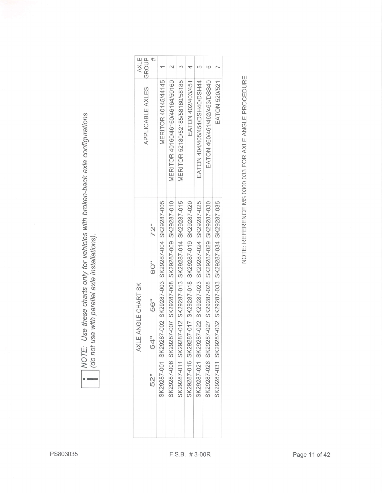
Refer to Figure
6 and Figure 7 for
examples
of
rear
axle angle bills.
Figure
6 Example
of
Rear
Axle Angle Information
Bill
(Parallel
Axle
Configuration)
PS803035
F.S.B.
# 3-00R
PageT
of 42
Figure
7 Example Rear
Axle Angle Information
Bill
(Broken-back
Axle Configuration)
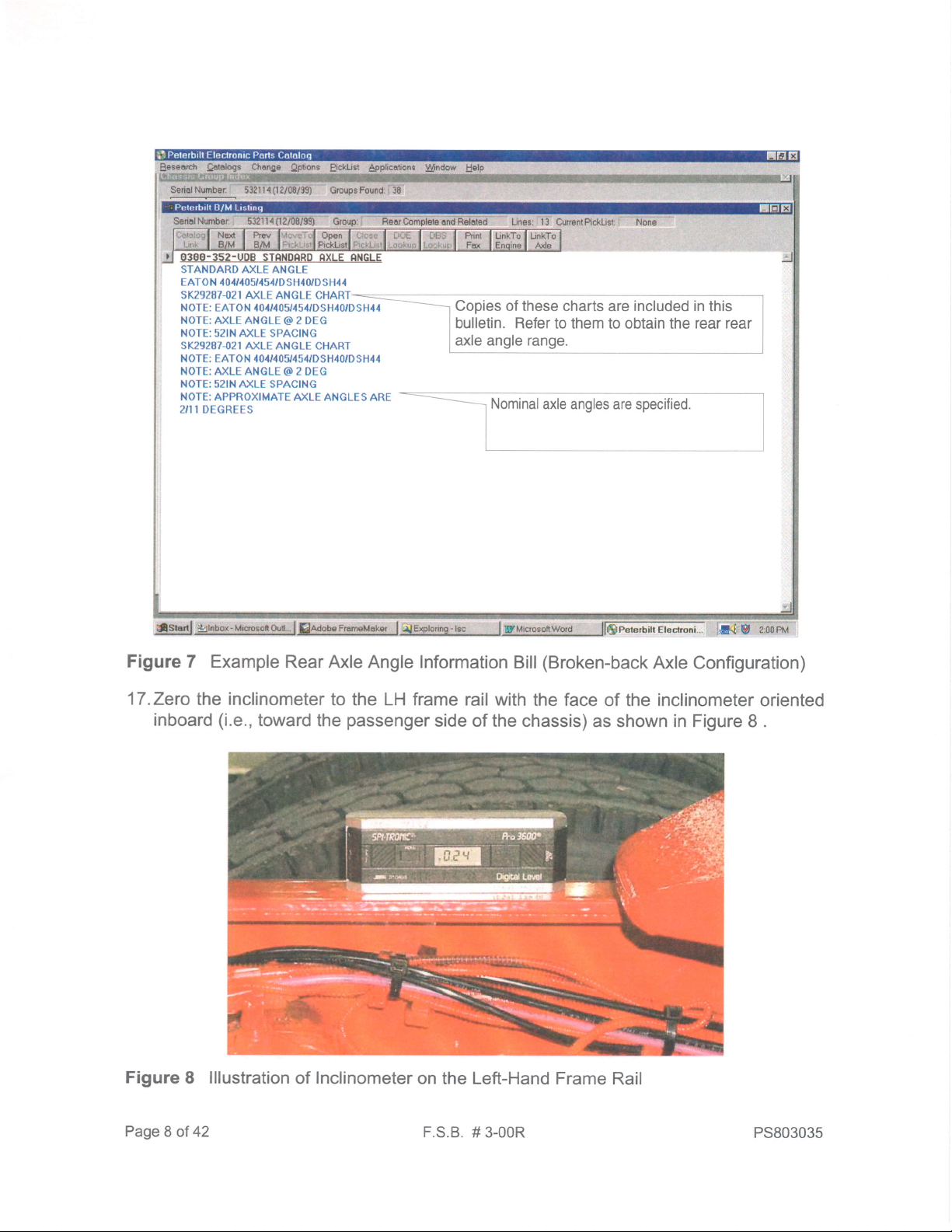
17.Zero
the inclinometer
to the LH frame rail with
the face
of the inclinometer oriented
inboard
(i.e.,
toward the
passenger
side of the chassis)
as shown in Figure 8 .
Figure
8 lllustration
of
Inclinometer
on the Left-Hand Frame
Rail
Page
8 of 42
F.S.B.
# 3-00R PS803035
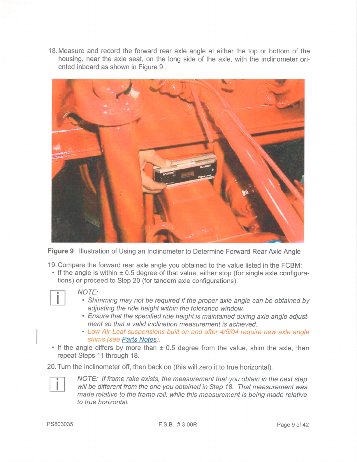
iB.Measure
and record the forwarci
rear axle
angie
housrng, near
the
axle seat, on the long
side of
ented
inboard
as
shown
in Fioure
9 .
/
\
at either the
ihe axle, with
top
or bottom of the
the
inclinometer
ori-
.#
Figure
I lllustration
of Using an Inclinometer
to Determine Forward
Rear Axle Angle
l9.Compare
the forward rear
axle angle
you
obtained
to the
value
listed in the FCBM:
'
lf
the angle is within t
0.5 degree of
that value, either
stop
(for
single axle configura-
tions)
or
proceed
to Step 20
(for
tandem
axle configurations).
NOTE:
'
Shinirning may not
be requireci if
the
proper
axle angle can be obtained
by
adjusting the ride height
within the
tolerance window.
'
Ensure
that the specified ride
height is
maintained
during axle angle adjust-
.
ment so
that a
valid
inclination measurement
is
achieved.
|e4s_l'/qteo
"
lf the
angle difters by more
than t 0.5
degree from
the
value,
shim the axle, then
repeat
Steps 11 through 18.
20.Turn
the
inclinometer
off, then back
on
(this
wiil zero it
to true horizontal).
NOTE: lf
frame rake
exists, the measurement
that
you
obtain in the next step
will
be different from
the one
you
obtaineci in Step 18. That measurement
was
maoe relative
to the frame rail,
while this measurement
is
beinq
made relative
to lrue horizontal.
\
rb
PS803035
F.S
B. # 3-00R
Page
I of
42
21. Remeasure
and record the forward rear
axle angle
(now
with respect
to the true hori-
zontal)
at either the top
or bottom of the housing, near
the axle seat, on the long side
of the axle, with
the
inclinometer
oriented inboard
as shown in Figure
9
.
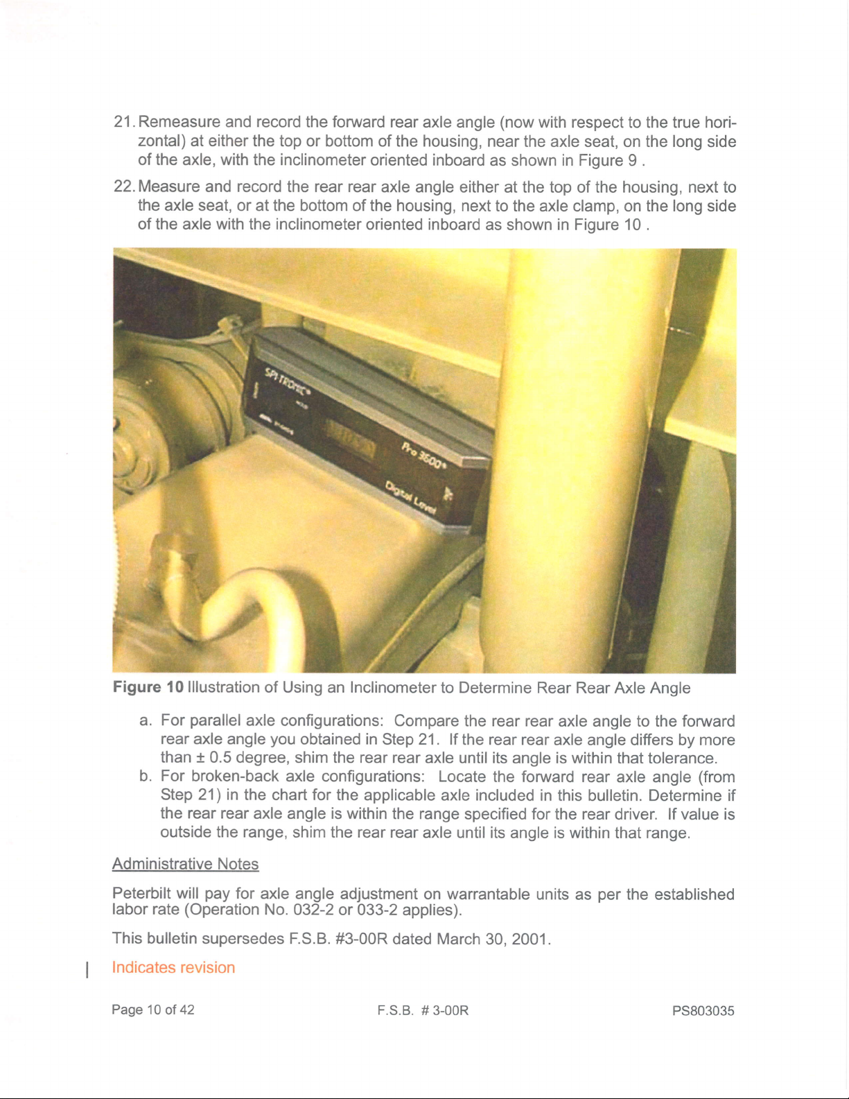
22.Measure
and record the rear rear
axle angle either
at the top of the housing,
next
to
the axle seat, or
at the bottom of the housing, next
to the axle clamp, on the long side
of the axle with the inclinometer
oriented inboard
as shown
in Figure 10 .
Figure
10 lllustration
of Using an Inclinometer
to Determine Rear
Rear Axle Angle
a.
For
parallel
axle configurations:
Compare the rear rear
axle angle to the forward
rear
axle angle
you
obtained in
Step 21 . lf
the
rear
rear axle angle
differs by
more
than
+
0.5 degree,
shim the rear rear
axle until its
angle
is within
that tolerance.
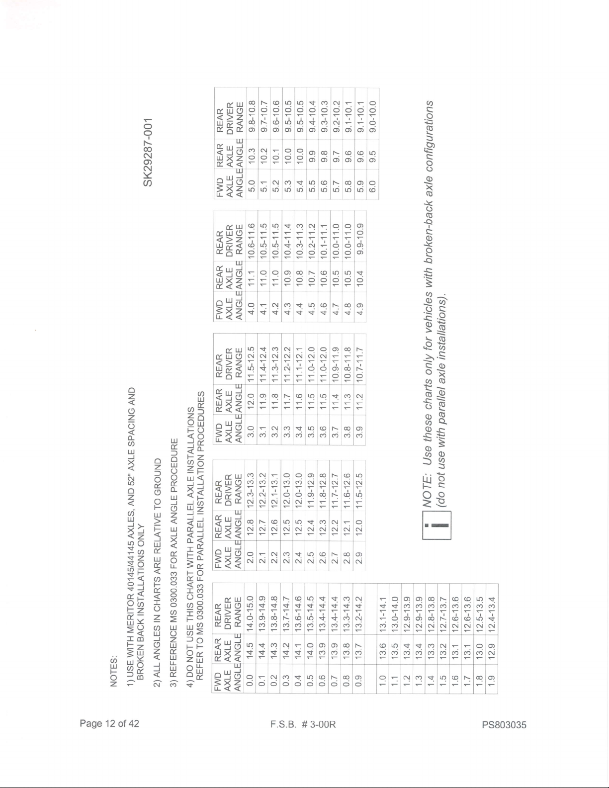
b. For
broken-back axle
configurations: Locate
the foruyard rear
axle angle
(from
Step 21) in
the chart for the
applicable axle included
in this bulletin. Determine if
the rear rear
axle angle is within
the range
specified for the rear driver. lf value is
outside the range,
shim the rear rear
axle until its
angle
is within
that range.
Administrative
Notes
Peterbilt
will
pay
for
axle angle
adjustment on warrantable
units as
per
the established
labor
rate
(Operation
No.
032-2 or
033-2 applies).
This
bulletin supersedes F.S.B.
#3-00R
dated March 30, 2001.
Indicates revision
Page
1O of 42
F.S.B.
# 3-00R
PS803035
ut
tr
f
o
uJ
o
o
tr
(L
lrJ
J
o
z
uJ
X
tr
o
lr
(Y)
(v)
q
o
o
(Y)
o
o
lrJ
o
z
lrJ
t
uJ
lr
uJ
t
ui
F
o
z
to
s
€
E
s
R
s
8
E
x
a
t
G
f
s
o
E
a
s
.E
sd
.gF
EE
e8
5.s
s*
OG
Fg
RQ
E8.
$E
sg
HR
9s
lu tL:+t
J]
.o
\E
F
N
(Y'
sf
ro
@
F-
a
IIJ
X
ut
@
o
=
I
(L
ro
sf
s
s
K'
$
o
t
tr
o
F
t
uJ
o
(o
o
u)
s
(o
@
s
o
@
@
\
c,
(o
o
$
tr
e.
IIJ
lo
@
@
ID
o
o
r
@
ro
r4t
@
ol
ro
o
@
F
(\
|o
t
F
e
ul
F
ro
{
(v)
o
{
N
o
$
z
o
F
t!
s
sf
-
a
o
b
sf
I
a
o
t
lo
{
r4t
o
s
t
o
s
z
o
F
Lrl
o
$
@
CN
o
(r)
(0
{
N
(o
{
(o
s
o
(o
s
z
o
F
ul
F
(\l
ro
o
(\l
ro
z
o
F
IrJ
3
N
N
b
o
Y
a
F
*b
oo
IJJ
J
o
z
IIJ
3.
JV
ao
N
o
lo
o
o
I
@
(\
o)
(\l
Y
a
I
o
t
@
(\l
ct)
ol
Y
a
c')
o
o
FI
@
(\
o)
6l
Y
U'
(\l
o
o
I
@
N
o
N
Y
o
o
o
I
o
(\l
CD
N
Y
a
o
o
*
@
ol
CD
ot
Y
@
o)
o
o
I
@
(\l
CD
ol
Y
a
@
o
o
I
@
C\
CD
6l
Y
a
o
o
t
@
N
CD
N
Y
a
(o
o
o
I
@
ol
CD
N
Y
o
t{)
o
t
@
(\
o)
6l
Y
U)
$
o
I
@
N
CD
(\
Y
o
(Y)
r
o
I
@
GI
CD
(\t
Y
a
(!
o
I
@
N
ct)
N
Y
a
F
o
I
@
ol
CD
(\l
!<
o
o
ol
o
I
@
ol
o)
6l
Y
o
CD
o
*
@
6l
CD
(\l
Y
U'
@
o
I
€
(\
qt
6l
Y
q,
o
I
@
(\l
CD
6l
Y
U'
@
o
I
@
ol
CD
6t
Y
a
to
(\l
o
I
@
C\I
o)
(\l
Y
o
N
o
I
@
N
o)
sl
Y
U'
(Y)
N
o
I
@
(\
g)
N
Y
o
(\l
N
o
I
@
(\
ct)
C\
Y
U'
N
?
€
ol
CD
N
Y
a
o
(l)
o
I
@
N
o)
ol
Y
U)
q)
N
o
I
o
6l
CD
ol
Y
U)
@
N
o
t
o
ol
CD
6l
Y
(t,
ol
o
I
@
(\l
o)
6t
Y
o
(o
(\
o
I
@
(\
o)
(\
Y
U'
K'
(v)
o
I
o
(\l
ct)
ol
Y
a
$
o
I
o
(\l
ct)
(\l
Y
a
c)
(Y)
o
I
o
(\t
o,
o,l
Y
U'
N
(v)
o
I
@
N
o)
ol
Y
a
(o
o
I
@
(\l
ct)
N
Y
a
Page 1'l
of
42
F.S.B.
# 3-00R
PS803035
q
c
s
e
5
P
c
o
o
e
x
G
A<
o
G
f
c
o
r<
Q
a
€
=
-Ea
or
G.9
sE
FS
5.S
qq)
oI
(aG
EE
EQ
E8.
.PS
:s
6c)
f,3
lrJ 9
c)o
=e.
Iq
oo
IE
'l'
qiq
o)
o)
.,I;
r]'
T
o
I
nl
o)l
i
o?
o)
I
u?l
to1
o
o?
o,
n
o
o?
{
qq
5rE
3ie
qu?
oo
-l-
\oq
$$
li
atc?iq:
;l;l;t;
a
a? ollr
ooo;o
FFFi-
tf t
o?oq\q
ololo
o
-1-1-l-
c?inlq q
ololo]=
I tl
aul
9lu?iQ
rulo
-lFlF
<>z TlTl.;
wp
<
(olrolto
t
^X.
ci
lci cj
Flr
-
trl] 1 I
tgdl-lc
q
uJxz
ir tF
F
t
<<
l-l-l-
lul
ll
e5d
ol-i*
t1<+l+l+
\jq
c\r
ic.,l
\le
==
I
ol
:
c!N
u?
N
I
u?
o
o.i
(t
d
d?
N
@
c.i
q
l'
n
llJ
F*
o
o
I
@
N
O)
c!
Y
@
"frU
<>z
lllt<
0lE,t
q
ll)
q
\f
o?
s
I
o,
c.j
oq
s
oq
(9
\
$
I
\
q
$
q
(f)
u?
v
q
(f)
n
$
n
CO
a
s
a
cf,
.f
I
c?
(9
ol
s
ol
cr)
s
q
s
o
o?
(9
o?
C\
o?
(r)
I
q
N
oq
(f)
oq
N
\
cf)
\
N
q
(o
I
q
N
q
I
q
N
;
I
u?
N
n
\
N
iri
UJXZ
t<<
lu?
ls
a
s
a?
s
c!
\f
s
q
s
o?
(v)
o?
oq
(o
\
(Y)
(o
ri
q
(9
a
(9
n
(o
a?
(o
q
(f)
<.i
(f)
c
(7)
N
f*?
o
d ci
N
o
c?
o
n
lu?
oo
q
o
\
oq
o
qr
c! cf)
Y
u? q
\
oq
I
"ffU
<>z
V_8fi
IU
tsa
|,J'jxz
tr
<<
?#
o9=
z
=o
fiqle
ilEHfri
;
H
9-22
$EEII#
$I
fi E =*
E3t
e EE
siglFaE
o
u.l
ex
q
I
q
o)
ci
\
o
I
1\
o;
q
o
oq
o
I
oq
o,
c?
o
tu
oauJ(9
<>z
rtJp<
E6t
TU
isu
uJxz
E<<
tu
(ur(,
<>z
VNfr
u?
N
q
n
N
I
a
c?
C!
I
a
c\l
N
I
c\l
c.i
I
q
N
q
c
N
q
-
o?
o
oq
I
@
c;
f-
N
isU
uJxz
t<<
q
(\
o?
oq
\
q q
rO .q
c?
c!
e5d
sxz
tL<<
o
c.j <'i
c!
(Y)
cin
(9
CO
l.()
c.j
(o
(f)
t\
c.j
@ o?
(o
q
N
@
ic.i
lF
l"c
l-
c?
N
u?q
NC!
o?
N
Y
ol
l=
I
in
lC\l
q
I
q
N
u?
(\I
a
N
c
(a
q
N
u?
N
a?
N
<'i
I
oi
q
ol
q
c!
c!
cf)
I
c!
N
\
N
c.i
PS803035
F.S.B.
#
3-00R
Page 12
of 42

q
q
o
e
R
o
o
e
x
G
f<
o
$
s
s
c)
.r<
e
a
=
P:.
te
E.e
ss
nff
5.S
qo
o>
(/)G
Eo
EQ
oF
(/J \<.
d)e
SE
:=
6a)
)3
Lll O
tl'
c
C)o
=e-
u?na?
ooo
:l:5
u?na?
or,o, o)
I
oQ
\;9
o olo
t5Y
oe\q
o)
o, o,
qo?
-O
TT
qo?
OO)
:
I
o
t:
I
o
tr*U
<>z
'"8fr
N
o
o
I
@
c!
o,
N
Y
a
tu
(r.uO
<>z
'"8fi
IIJ
*5d
wxz
t
<<
oq
N
oq
ni
\
N
I
\
(\l
N
@(o
c.i c.i
TT
(o(o
I
c.i
I
c.i
qna?
NN(\T
T-;:
q
nlc?
r r':-
q
Io?
oq
N--
c!
r.r
NNN
ITT
Nrr
---
IT
\qq
F*?
c
N c.j
qc?
NN
a
(\l
1rllq
*lN
\q
NN
o?
C\l
"ffU
S
<>z \
uJt<
ro
E^t
c.)
Y
s
n
(7'
c? e!
9S
TT
(tN
c.i c.j
:qo?
\t \t
(fJ
557
:qo?
(f)
,(f)
c!
o?oq\
(o
(f) (o
r:5
o?,0q
\
NNN
J
qu?
cD
l(f)
EE
NN
a
I
n
N
a
(f)
n
N
("?
I
N
c!
(f,
c.l
N
d
oi
c
q
N
o?
N
I
o?
o?
N
-
{sdl"
uJxz
s
E<<
-
o?
(f)
o
d
t\ q
(o
lr)
(?)
a n
(f)
N
<.i <"i
d c.j
O)
N
oq
N
\
C\I
q
N N
n
N
a
N
;t:ls
d
C\l
,a?
oio
.t |r?
o
q
o
\
i09
oo
o
Oir
--
o! c?
a
rn
\
oq
o?
?,s
rt
q5H
i
ee
fr5
;
r
9i2
$gEilgE
fg
ZE
fiE
p,ag3[iF
{99
?
uEfl 3
tsHl.
H{?r.
o{
o
ry
o,
\
o)
:
oi
q
o,
o
I
o
o;
u?
O)
o? oq
?9
o?
oq
@€o
o)
a
o,
oq
o)
oq
@
a?
o,
F-
(O
tO
++"
f\
(O
tO
ddd
c!rq
o) o) o)
R
O)
I
Y
@
o?
si9;
rJ-<<
d
q
r() 1r)
a
ro
u?q
lo tr)
\qo?
lrjtolr)
Y
gorco
3"tot
rq
io
o
z
$
l\
lco
9rt
au?q
s s]s
C.l c?
st
I
$
c
s
n
I
a
o
oq\
5t
oq\
oo
o?
I
o?
s
c
N
I
q
rrq
I
u?q
(f)(f)
Page
13
of
42
F.S.B.
# 3-00R
PS80303s
 Loading...