

Page 1

Quick Table of Contents
Introduction ..................................................................................................... 1
Electric Power System.................................................................................... 7
Heating and Air Conditioning System......................................................... 25
Troubleshooting............................................................................................ 41
Page 2

Page 3
PART 1: INTRODUCTION Safety Signals
Figure -1
PART 1: INTRODUCTION
Safety Signals
A number of alerting messages are in this manual. Please
read and follow them. They are there for your protection
and information. These messages can help you avoid
injury to yourself and your passengers, and help prevent
costly damage to the vehicle.
Key symbols and “signal words” are used to indicate what
kind of message is going to follow. Pay special attention to
instructions prefaced by symbols and signal words
“WARNING,” “CAUTION,” or “NOTE.” Please do not ignore
any of these alerts.
Figure -2
When you see this symbol and word, the message that follows is especially vital. This signals something that can
cause injury or even death. This message will tell you what
the hazard is, what can happen if you don’t heed the warning, and how to avoid it. For example:
Figure -3
Figure -4
WARNING:
WARNING! Do not carry additional fuel containers in your vehicle. Fuel containers, either
full or empty, may leak, explode, and cause or
feed a fire. Do not carry extra fuel containers.
Even empty ones are dangerous.
Figure -5
Figure -6
CAUTION:
This symbol and word signals something that could damage your vehicle. For example:
Figure -7
CAUTION: Continuing to operate your vehicle
with insufficient oil pressure will cause serious
Figure -8
engine damage.
R(09/07) Y53-6017 – 1 –
Page 4

Safety Signals PART 1: INTRODUCTION
NOTE:
Figure -9
Gives you information we feel you would like to
have. It could have to do with care of your vehi-
i
cle or with driving more efficiently. For example:
Figure -10
NOTE: Pumping the accelerator will not assist in
starting the engine.
i
Figure -11
Please take the time to read these messages when
WARNING!
Something that could cause an injury or even death.
CAUTION:
Something that could cause damage to your vehicle.
NOTE:
Useful information.
you see them, and remember:
– 2 – Y53-6017 R(09/07)
Page 5

PART 1: INTRODUCTION The Peterbilt ComfortClass™ System
The Peterbilt ComfortClass™ System
This system utilizes a sleeper air conditioning system and
diesel fuel-powered sleeper heater that are compliant with
anti-idling requirements. The sleeper air conditioning system provides up to 10 hours of engine-off cooling in typical
conditions
vehicle is driven or by shore power and requires approximately 4-6 hours of recharging depending upon outside
conditions. The cold air for the air conditioning system
comes from a Storage Cooler that is located behind the
sleeper. It stores the system’s cooling capacity by freezing
water. As the system is used, the ice melts back into water
and needs to be recharged (frozen) again by the Air Conditioning Charge Unit.
The system is powered by an energy-efficient ComfortClass System Battery Box that includes four deep-cycle
AGM batteries and is outfitted with 2000 watt, 12 VDC/120
VAC inverter. The system includes a 20 amp shore power
capability with a 25-foot shore power cable and includes
ComfortClass System battery charging capability while on
shore power.
The system has an enhanced charge/start capability that
includes two 1000 CCA dedicated Starter Batteries in the
*
. The air conditioning system recharges as the
starter battery box, a starter battery charger and a 185A
alternator with remote voltage regulator located in the
ComfortClass System Battery Box. The voltage regulator is
optimized and pre-programmed with a specific charge profile for optimal charging of the deep-cycle batteries that
increases the deep-cycle battery life.
An enhanced insulation package includes upgraded
sleeper in-wall insulation. Interior features include the following:
• Floor insulation,
• A cab dash-mounted A/C charge enable switch,
• Two 120 VAC, GFCI (ground fault circuit interruption)
duplex outlets in passenger side closet and under
driver side bunk,
• A dedicated sleeper control panel with diagnostic feedback, via “blink” codes (status of HVAC modes,
inverter modes, alerts, etc.),
• Sleeper fresh or recirculated air intake, and
• A premium-grade dust and pollen filter readily accessible under sleeper bunk.
*
Overall performance may vary depending on conditions described on page 33.
R(09/07) Y53-6017 – 3 –
Page 6

The Peterbilt ComfortClass™ System PART 1: INTRODUCTION
System features include:
• Engine-off sleeper heating, cooling, and 120-Volt AC
power.
• No engine noise or vibration.
• Decrease in overall fuel consumption.
Figure -12
NOTE: This system is NOT designed to cool a
hot sleeper. Use the vehicle’s air conditioner to
i
pre-cool the sleeper to at least 75°F prior to turning on the ComfortClass System air conditioner.
The system can then be used to maintain that
temperature.
Figure -13
NOTE: The system is designed to maintain the
interior sleeper temperature around 75°F for a
i
period of up to 10 hours
outside temperature of 95°F, a relative humidity
of 50%, and with the sleeper not in direct sunlight. The sleeper environment must be
pre-cooled to 75°F by the air conditioner prior to
use of the system. The system is NOT designed
to maintain sleeper temperatures under
extremes of heat or direct sunlight. You may
need to supplement the ComfortClass System by
operating the vehicle’s air conditioner if the ComfortClass System is unable to maintain the
desired temperature level.
* Overall performance may vary depending on conditions
described on page 33.
This Operator’s Manual contains useful information for the
safe and efficient operation of your ComfortClass System.
All information contained in this manual is based on the latest production information available at the time of publication. Peterbilt Motors reserves the right to make changes at
any time without notice.
*
, based on maximum
– 4 – Y53-6017 R(09/07)
Page 7
PART 1: INTRODUCTION The Peterbilt ComfortClass™ System
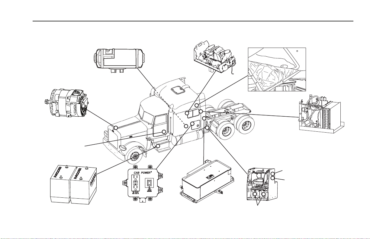
Location of Components
Figure 1
Air Handler
(Under Lower Bunk)
uel-Fired Heater
F
(in passenger’s side
toolbox)
Enhanced Insulation
High Output Alternator
Air Conditioning
Starter Batteries
Disconnect Switch
ComfortClass System
Battery Disconnect Switch
Charge Unit
Shore Power Connector
ComfortClass System
Battery Box
Starter Batteries
Figure 2
Circuit Breaker Box
(located in driver’s side toolbox)
Storage Cooler
(Behind Sleeper)
ComfortClass System Batteries
PB00001
R(09/07) Y53-6017 – 5 –
Page 8
The Peterbilt ComfortClass™ System PART 1: INTRODUCTION
g
Location of Components
Figure 3
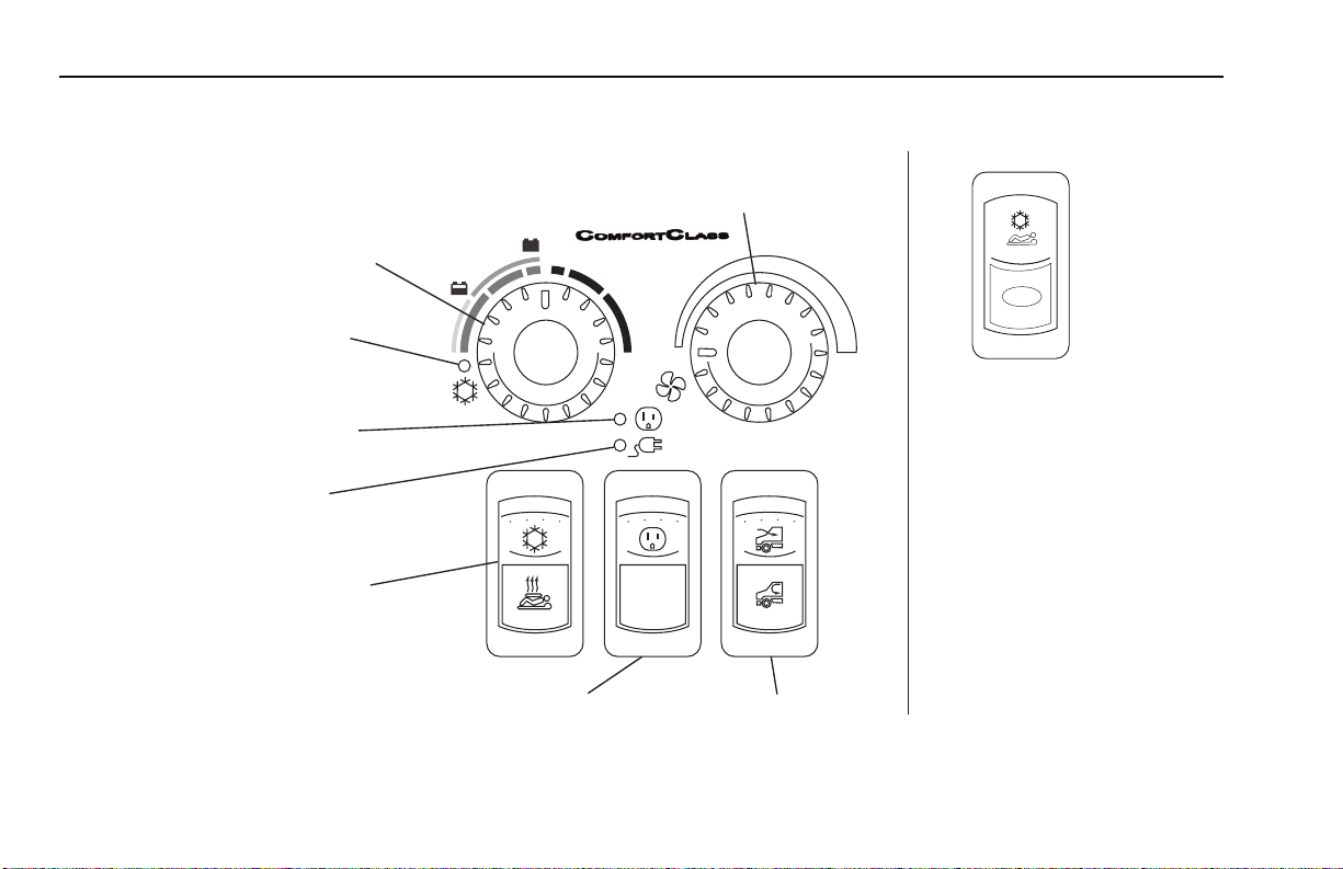
Sleeper Control Panel
(located in Sleeper)
Fan Control Dial
(Page 26)
Temperature Control Dial
CHARGE
(Pages 29 & 32)
Air Conditioner Pump
ON Lamp (Green)
(Page 26)
OFF
Charge/Enable Switch
(located on cab dash)
Inverter/Charger Lamp
(Page 37)
(Page 19)
Shore Power Lamp
NORMAL
(120-Volt AC)
(Page 19)
Air Conditioning/Heating
Switch
(Pages 29 & 32)
Inverter/Charger Switch
(Page 18)
Figure -14
OFF/RESET
Sleeper Fresh/Recirculation Air
Switch
(Pa
e 27)
PB00002
– 6 – Y53-6017 R(09/07)
Page 9
PART 2: ELECTRIC POWER SYSTEM Charging/Jump-Starting Instructions
Figure -15
PART 2: ELECTRIC POWER SYSTEM
Charging/Jump-Starting Instructions
Figure -16
Figure -17
Figure -18
WARNING! The electrical charging system
used for the ComfortClass System is different
from normal charging systems. Failure to
adhere to the proper charging or jump-starting
procedures could lead to death or serious
injury, damage to the Inverter/Charger or vehicle damage. Follow the Charging/Jump-Starting Instructions on page 10.
NOTE: The charging/jump-starting instructions
can also be found on the top of the ComfortClass
i
System Battery Box cover.
Figure -19
Starter Batteries
Figure -20
ComfortClass System
Batteries
PB00006A
Vehicles equipped with the ComfortClass System have
battery configurations that are different from traditional
vehicles. These vehicles have a dedicated set of batteries
in addition to the Starter Batteries. These batteries are
referred to as the “ComfortClass System Batteries.” These
batteries provide power to the vehicles’ electrical demands
including on-board computers and the starting batteries.
The starter is the only electrical device that does not
depend on the ComfortClass System Batteries. The schematic on page 9 is provided to help illustrate the system.
R(09/07) Y53-6017 – 7 –
Page 10

Charging/Jump-Starting Instructions PART 2: ELECTRIC POWER SYSTEM
Figure -21
NOTE: Do not attempt to jump-start the vehicle
without first reading the instructions on top of the
i
ComfortClass System Battery Box cover. If you
have a battery problem, it is best to contact an
authorized repair facility or a reputable towing
service. When you do, inform them of the charging instructions on page 10 and the wiring schematic on page 9. These instructions can also be
found on the top of the ComfortClass System
Battery Box cover.
– 8 – Y53-6017 R(09/07)
Page 11
PART 2: ELECTRIC POWER SYSTEM Charging/Jump-Starting Instructions
Figure 4
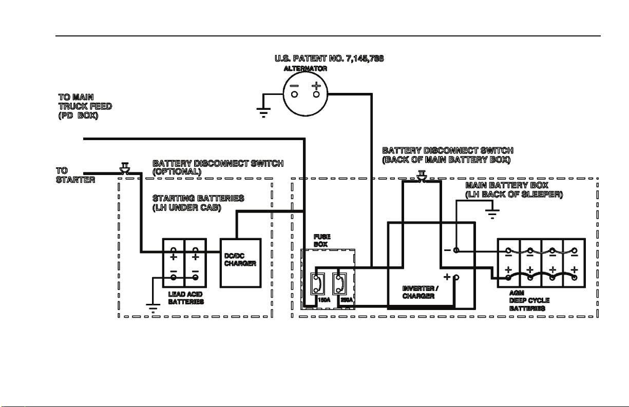
Wiring Schematic
Figure 5
R(09/07) Y53-6017 – 9 –
Page 12

Charging/Jump-Starting Instructions PART 2: ELECTRIC POWER SYSTEM
The ComfortClass System Batteries are located in the
ComfortClass System Battery Box behind the sleeper, on
the driver’s side. They power all electrical systems on the
vehicle EXCEPT the starter motor.
Figure -22
NOTE: Because the ComfortClass System Batteries power the engine controls and starter
i
relay, you may experience a no-crank condition if
the ComfortClass System Battery voltage is
below 9.5-Volt, even though the Starter Batteries
are fully charged.
Figure -23
NOTE: A DC/DC charger, also located below
the cab on the driver’s side, serves to isolate the
i
starting batteries from the ComfortClass System
Batteries and provides charge to the starting batteries to maintain them at a minimum of 12-Volt.
Figure -24
NOTE: The DC/DC charger will only be activated when either the truck is running or the
i
truck is attached to a shore power electrical supply and the key is in the IGN or ON position.
Charging/Jump-Starting Instructions
There may be occasions where the vehicle will crank but it
will not start, even after charging the starting batteries
and/or attempting to jump-start the vehicle using normal
procedures found in the Operator’s Manual. You may also
notice that the voltage meter on your dash is below 11
volts, interior lights are dimmed or not on, and the DC outlets have no power.
Figure -25
NOTE: The voltmeter only monitors the ComfortClass System Batteries, not the Starter Batteries.
i
In such situations, the ComfortClass System System Battery voltage has dropped below 9.5 volts. It is necessary to
charge the ComfortClass System System Batteries to
above 11 volts (and ensure that the Starter Batteries are at
12 volts) in order to start the vehicle.
– 10 – Y53-6017 R(09/07)
Page 13
PART 2: ELECTRIC POWER SYSTEM Charging/Jump-Starting Instructions
Figure -26
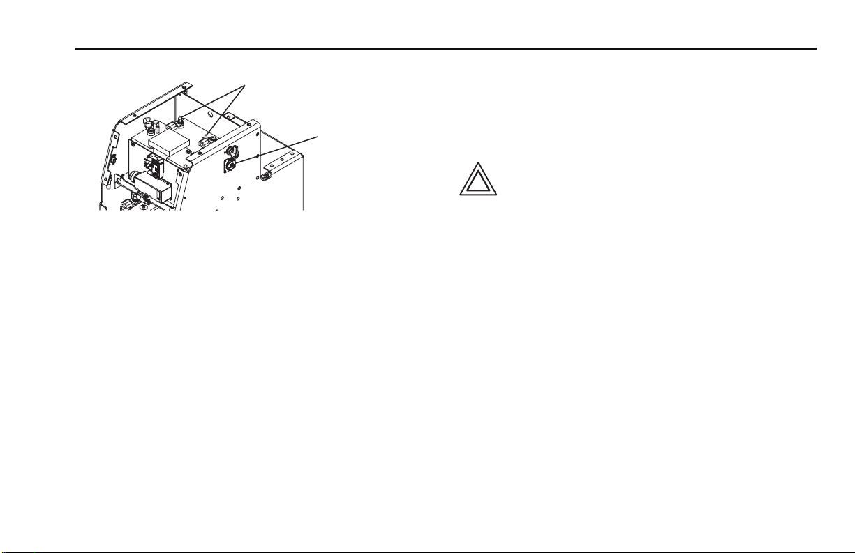
Charging Terminals
Shore Power
Connector
Figure -27
PB00032
The ComfortClass System Batteries are located in the
driver’s side frame-mounted box located behind the
sleeper. The batteries can be accessed by removing the
cover plate and connecting a charger to the charging terminals. Turn the battery disconnect switch, on the side of the
ComfortClass System Battery Box, to the “ON” position if
you want to charge the batteries using the charging terminals. Charging these batteries can also be performed by
using the shore power connection on the side of this box.
Please have your ComfortClass System inspected by an
authorized dealer if your ComfortClass System Batteries
continue to drop below 11 volts or if you are unable to start
the vehicle after charging both the starter and the ComfortClass System Batteries.
Refer to “Battery Charging” and “Jump-Starting Vehi-
cles” in the Peterbilt Operator’s Manual for additional bat-
tery charging and jump-starting procedures. Also, refer to
the Troubleshooting Section on page 41 for more
details.
Figure -28
CAUTION: Do not connect any accessories
directly to the starting batteries. This could
Figure -29
drain the batteries to a point where they can no
longer start the engine.
R(09/07) Y53-6017 – 11 –
Page 14
Charging/Jump-Starting Instructions PART 2: ELECTRIC POWER SYSTEM
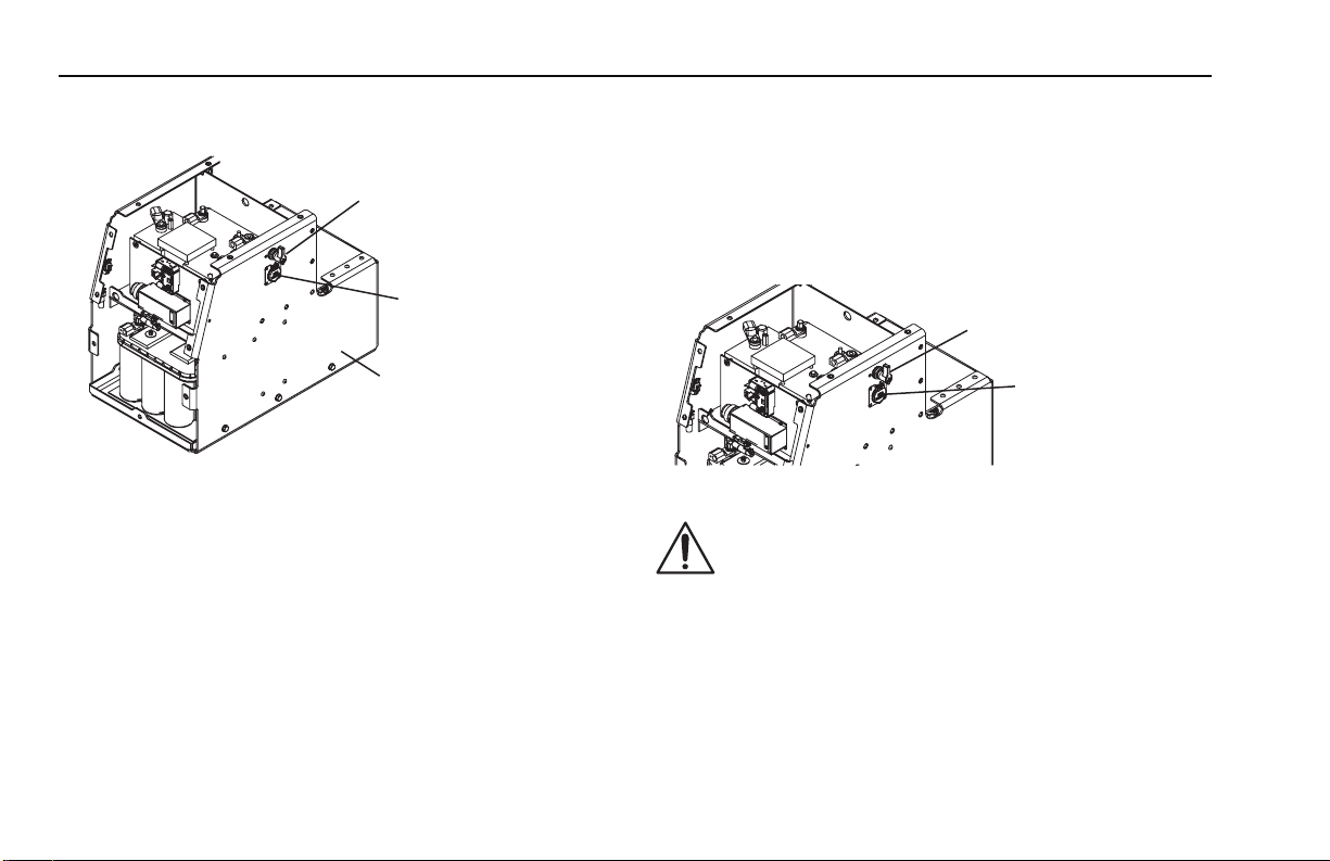
Disconnect Instructions
Figure -30
ComfortClass System
Batteries Disconnect
Switch (shown in the
off position)
Shore Power
Connector
ComfortClass System
Battery Box
PB00004
Figure -31
Prior to servicing the vehicle, disconnect the electrical system as follows:
1. Turn air heater off and wait three minutes prior to
turning the disconnect switches to the OFF position
(steps 3 and 4 below). This gives three minutes for
the heater to purge any fuel still in the heater and
allows the unit to cool off.
2. Unplug shore power connection.
3. Turn Starter Battery disconnect to OFF position.
4. Turn ComfortClass System Battery disconnect
located on ComfortClass System Battery Box
(located on driver’s side, rear of sleeper) to OFF
position.
Charging ComfortClass System Batteries using Shore Power
Figure -32
Figure -33
Figure -34
WARNING! Electric Shock Hazard. 120-Volt AC
ComfortClass System
Batteries Disconnect
Switch
Shore Power
Connector
PB00005
power present. This can cause electrical shock
Figure -35
or fire resulting in death, personal injury or
property damage. Only a trained technician
should work on the shore power system. Turn
all battery disconnect switches to the OFF
position and unplug the shore power electrical
supply before servicing any part of the vehicle’s electrical system.
– 12 – Y53-6017 R(09/07)
Page 15

PART 2: ELECTRIC POWER SYSTEM Charging/Jump-Starting Instructions
Figure -36
Figure -37
Figure -38
Figure -39
WARNING! Electric Shock Hazard. 120-Volt AC
power present. An improperly maintained
shore power electrical system can cause fires
and electrical shocks that may lead to death,
personal injury or property damage. Regularly
inspect the shore power truck wiring, AC shore
power cord, plugs and connectors for damaged or frayed wiring. Do not use the shore
power system if there are any signs of problems.
WARNING! Do not use an undersized AC
extension cord or a cord that is too long as
there is an Electric Shock Hazard due to the
120-Volt AC power present. An undersized AC
extension cord can cause fires and electrical
shocks that may lead to death, personal injury
or property damage. Always use a properly
grounded 20 Amp UL rated AC extension cord
that is no longer than 25 ft. and a 20 Amp AC
protected power source with a grounding conductor when connecting to a shore power electrical supply.
1. Attach the shore power cord to a 20 Amp protected
circuit and the shore power connector until system
voltage is restored (9.5 Volts minimum at ComfortClass System Batteries and 12 Volts minimum at
Starter Batteries). The shore power connector is
located on the rear of the ComfortClass System Battery Box.
2. Make sure the Inverter/Charger Switch (shown on
page 20) is in the ON position and that the circuit
breaker on the Protection Unit box has not been
tripped. The Shore Power Lamp on the Sleeper Control Panel will illuminate green and the
Inverter/Charger Lamp will illuminate orange.
Normal system voltage is 13.5 to 14.6 Volts with the
engine running. Typically the ComfortClass System Batteries must reach at least a 9.5-Volt charge to power the
engine controls necessary to start the engine.
R(09/07) Y53-6017 – 13 –
Page 16

12-Volt DC System PART 2: ELECTRIC POWER SYSTEM
12-Volt DC System
Figure -40
Starter Batteries
Figure -41
The 12-Volt Direct Current (DC) System consists of ComfortClass System Batteries, Starter Batteries, a Low Voltage Disconnect system and gauges for Electrical
Monitoring. Vehicles equipped with the Peterbilt ComfortClass System have a unique 12-Volt electrical system. The
system uses a high output alternator and two sets of batteries: the ComfortClass System Batteries and the Starter
Batteries.
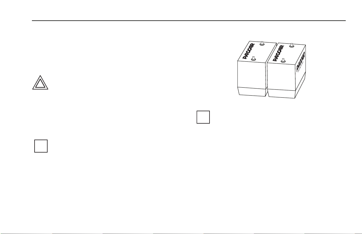
ComfortClass System Batteries
PB00006A
ComfortClass System
Figure -42
ComfortClass System Batteries
Deep-Cycle AGM (Gel Cell)
Figure -43
Figure -44
WARNING! Do not cover the batteries with
additional insulation or covers or store any
Figure -45
items around the batteries. Additional insulation or items around the batteries will lead to
poor venting which could result in a fire and/or
explosion that may lead to death, personal
injury or equipment damage.
Batteries
PB00007
– 14 – Y53-6017 R(09/07)
Page 17
PART 2: ELECTRIC POWER SYSTEM 12-Volt DC System
The ComfortClass System Batteries are located in the
ComfortClass System Battery Box on the driver’s side of
the vehicle behind the sleeper compartment. The four
Deep Cycle AGM (Gel Cell) batteries power all electrical
system components on the vehicle EXCEPT the starter
motor.
Figure -46
CAUTION: Do not replace the Deep Cycle AGM
(Gel Cell) batteries with common lead acid bat-
Figure -47
teries. The ComfortClass System is designed
to draw to very low voltages which will significantly reduce the life of a lead acid battery. Use
only PACCAR recommended ComfortClass
System Batteries. See your Peterbilt dealer for
additional information.
Figure -48
NOTE: Because the ComfortClass System Batteries power the engine controls and starter
i
relay, you may experience a no-crank condition if
the ComfortClass System Battery voltage is
below 9.5-Volt, even though the Starter Batteries
are fully charged.
Starter Batteries
Figure -49
Figure -50
Figure -51
PB00008
NOTE: The charging instructions can also be
found on the top of the ComfortClass System
i
Battery Box cover.
The Starter Batteries (two 1000 Cold Cranking Amp
12-Volt batteries) are located below the cab on the driver’s
side of the vehicle. These batteries are used only to power
the starter motor.
A DC/DC charger serves to isolate the starting batteries
from the ComfortClass System Batteries and provides
charge to the Starter Batteries to maintain them at a minimum of 12 Volts.
R(09/07) Y53-6017 – 15 –
Page 18

12-Volt DC System PART 2: ELECTRIC POWER SYSTEM
Figure -52
NOTE: The DC/DC charger will only be activated when either the truck is running or the
i
truck is attached to a shore power electrical supply and the key is in the IGN or ON position.
Low-Voltage Disconnect
Figure -53
NOTE: The electrical system is equipped with a
low-voltage disconnect feature that will shut
i
down all non-essential electrical components if
ComfortClass System Battery voltage drops
below 11 Volts.
The system is designed to disconnect when ComfortClass
System Battery voltage drops below 11 Volts. Three minutes prior to system disconnect, an audible warning in the
Sleeper Control Panel will sound to give the operator time
to switch to an alternative power source or reduce loads.
To reset the system the ComfortClass System Batteries
must be charged until a system voltage of 13.2 Volts or
greater is reached. This can be accomplished by attaching
to shore power or starting the engine. Turning the ignition
key to the ON position will not disable the Low-Voltage Disconnect.
Electrical System Monitoring
Normal system voltage on vehicles equipped with the
Peterbilt ComfortClass System is between 13.5 and 14.6
Volts with the engine running. This is slightly higher than
vehicles without the Peterbilt ComfortClass System.
All vehicles come equipped with a dash-mounted voltmeter. Some vehicles may be equipped with an optional
ammeter as well.
Figure -54
NOTE: These gauges monitor the ComfortClass
System Batteries, not the Starter Batteries.
i
An indicator lamp on the face of the voltmeter will illuminate if system voltage reaches 15 Volts. This is considered
an over voltage condition. If this occurs, contact the nearest authorized repair facility.
– 16 – Y53-6017 R(09/07)
Page 19

PART 2: ELECTRIC POWER SYSTEM Shore Power
Shore Power
Figure -55
Figure -56
Figure -57
Figure -58
WARNING! Electric Shock Hazard. 120-Volt AC
power present. This can cause electrical shock
or fire resulting in death, personal injury and/or
property damage. Only a trained technician
should work on the shore power system. Turn
all battery disconnect switches to the OFF
position and unplug the shore power electrical
supply before servicing any part of the vehicle’s electrical system.
The shore power system is located in the ComfortClass
System Battery Box and consists of a 120-Volt AC Electrical System connection, Inverter/Charger, Circuit Breaker
Box, and 120-Volt AC outlets in the sleeper.
Shore Power and Inverter
Figure -59
Shore Power
Connector
ComfortClass System
Battery Box
PB00010
Shore Power Hook Up
PB00006B
Figure -60
R(09/07) Y53-6017 – 17 –
Page 20

Shore Power PART 2: ELECTRIC POWER SYSTEM
Figure -61
WARNING! Electric Shock Hazard. 120-Volt AC
power present. An improperly maintained
Figure -62
Shore Power electrical system can cause fires
and electrical shocks that may lead to death,
personal injury or property damage. Regularly
inspect the shore power truck wiring, AC shore
power cord, plugs and connectors for damaged or frayed wiring. Do not use the shore
power system if there are any signs of problems. Always use a properly grounded 20 Amp
UL rated AC extension cord that is no longer
than 25 ft. and a 20 Amp AC protected power
source with a grounding conductor when connecting to a shore power electrical supply.
The Peterbilt ComfortClass System enables you to access
120-Volt AC power from two different sources. A shore
power connection allows access to an outside power
source and an electrical inverter system can produce
120-Volt AC from the ComfortClass System Batteries.
Inverter/Charger Switch
Figure -63
PB00011
Figure -64
The 120-Volt AC system function is controlled by the
Inverter/Charger Switch located on the Sleeper Control
Panel.
When the top of the switch is pressed (NORMAL position),
the Inverter/Charger is on and the green electrical outlet
symbol on the switch will turn on. This is the normal operating position for the Inverter/Charger.
When the bottom of the switch is pressed (OFF/RESET
position), the Inverter/Charger will be off and the green
electrical outlet symbol on the switch will turn off. Refer to
the Inverter/Charger Indicator Chart on page 20 for
Reset information.
– 18 – Y53-6017 R(09/07)
Page 21

PART 2: ELECTRIC POWER SYSTEM Shore Power
Inverter/Charger & Shore Power Lamps
Figure -65
Inverter/Charger Lamp
Shore Power Lamp
Figure -66
PB00011A
The Inverter/Charger and Shore Power Lamps located in
the center of the Sleeper Control Panel will illuminate in an
array of colors and configurations to designate system status. Refer to the Inverter/Charger Indicator chart on the
next page for more information.
R(09/07) Y53-6017 – 19 –
Page 22

Shore Power PART 2: ELECTRIC POWER SYSTEM
Inverter/Charger Indicator Chart
Figure 6
Inverter/Charger & Shore Power Lamps Status
Inverter/Charge
Inverter/Charger Lamp
Shore Power Lamp
Switch
Solid Green OFF ON OFF
Shore
Power
System Status
Inverter Charger
ON
OFF
(0.5 sec ON, 0.5 sec OFF)
Blinking Green
Blinking Green
3x (0.2 sec ON/OFF) 4.5 sec OFF
Blinking Green
(0.5 sec ON, 0.5 sec OFF)
OFF
OFF ON OFF Input Low Voltage Warning OFF
OFF ON
ON OFF Input Low Voltage
OFF
Input Over Voltage Protection OFF
OFF
Overload; Short Circuit
Solid Red
OFF ON
OFF
Protection; Output Over Voltage
OFF
Protection
OFF
OFF
ON
OFF Over Temp OFF
Solid Orange Solid Green ON ON OFF ON
Solid Orange
Solid Orange
Solid Green
Solid Green
ON
ON
ON
OFF
ON OFF
Thermally Derated Charge
Overload;
Short Circuit Protection
Blinking Orange/Red
(4 sec Orange, 1 sec Red)
Blinking Orange/Red
(0.5 sec Orange, 0.5 sec Red)
OFF
OFF
Figure 7
Solid Green
Solid Green
OFF
OFF
ON ON
ON ON
ON
OFF
OFF
Low Voltage Timed Charge
OFF Low Voltage Auto-Stop
Battery Disconnect
OFF
– 20 – Y53-6017 R(09/07)
Page 23

PART 2: ELECTRIC POWER SYSTEM Shore Power
g
p
g
y
y
Figure 8
Inverter/Charger & Shore Power Lamps Status
Inverter/Charger Lamp Shore Power Lamp
Remedy
Solid Green OFF Normal inverter/charger operation, no action required.
(0.5 sec ON, 4.5 sec OFF)
Blinking Green
Blinking Green
3x (0.2 sec ON/OFF) 4.5 sec OFF
Blinking Green
(0.5 sec ON, 0.5 sec OFF)
OFF
OFF
OFF
Solid Red OFF
OFF
OFF
Solid Orange Solid Green
Solid Orange Solid Green
Solid Orange Solid Green
Blinking Orange/Red
(4 sec Orange, 1 sec Red)
Blinking Orange/Red
(0.5 sec Orange, 0.5 sec Red)
OFF
OFF
1
If after restarting the inverter/charger the blink code persists, please see your local Peterbilt service dealer.
2
Continuous charging of low voltage batteries is not recommended. If low voltage charging is unsuccessful after restarting inverter/charger, replace main batteries.
Figure 9
Solid Green
Solid Green
OFF
OFF
- Inverter/char
- Cycle inverter/charger on/off switch to off/reset and then back on to reset inverter.
- Inverter/charger will auto-restart if voltage reaches an acceptable level.
- Cycle inverter/charger on/off switch to off/reset and then back on to reset inverter.
- Inverter/char
- Cycle inverter/charger on/off switch to off/reset and then back on to reset inverter.
- Cycle inverter/charger on/off switch to off/reset and then back on to reset inverter.
- Inverter/charger will auto-restart if temperature reaches an acceptable level.
- C
cle inverter/charger on/off switch to off/reset and then back on to reset inverter.
Normal inverter/charger operation, no action required.
Charging will derate at high temperatures, no action required.
- Inverter/charger will auto-restart if conditions reach an acceptable level.
- C
cle inverter/charger on/off switch to off/reset and then back on to reset inverter.
Low voltage charging operation, allows for charging of batteries as low as 5V, no action
required.
If batteries at a low voltage are not successfully accepting a charge, inverter/charger will turn
off. Cycle inverter/charger on/off switch to off/reset and then back on to reset
inverter/charger.
Turn inverter/charger on/off switch to off/reset. Reconnect batteries to inverter/charger. Turn
inverter/charger on/off switch to on.
For inverter/charger function, turn inverter/charger on/off switch to on.
er will auto-restart if voltage reaches an acce
er will auto-restart if voltage reaches an acceptable level.
1,2
table level.
1
1
1
1
1
1
R(09/07) Y53-6017 – 21 –
Page 24

Shore Power PART 2: ELECTRIC POWER SYSTEM
Circuit Breaker Box
Figure -67
Circuit Breaker Box
20 Amp
Circuit Breaker
Circuit Breaker Box
(GFCI)
Figure -69
WARNING! Electrical shock hazard. Use of a
ground fault circuit interrupter other than that
Figure -70
supplied with the Circuit Breaker Box may fail
to operate properly and may lead to death, personal injury or equipment damage. Use only
the ground fault circuit interrupter that is supplied with the Circuit Breaker Box (Hubbell Part
Number GFBF20GYL GFCI).
The Circuit Breaker Box houses a 20 Amp circuit breaker
and a Ground Fault Circuit Interrupter (GFCI) that provides
circuit protection for the 120-Volt AC system. (The Circuit
Breaker Box is located in the tool box on the driver’s side
of the sleeper.)
The circuit breaker is located on the right side of the Circuit
Breaker Box. If the breaker is tripped (circuit open) it can
be reset by pressing the top of the rocker switch to the ON
position.
The GFCI is located on the left side of the Circuit Breaker
Box. The GFCI will open (disconnecting the power) if a
ground fault is detected on the circuit. The unit can be
reset by pressing the RESET button on the top of the
GFCI.
Figure -68
PB00012
– 22 – Y53-6017 R(09/07)
Page 25

PART 2: ELECTRIC POWER SYSTEM Shore Power
Figure -71
NOTE: Replace GFCI if light on GFCI flashes. If
this is not done, outlets will not be powered.
i
Replace with a new Hubbell GFBF20GYL GFCI.
120-Volt AC Outlets
Figure -72
120-Volt AC Outlets
Figure -73
PB00013B
Two 120-Volt AC duplex style outlets are located in the
sleeper compartment, one under the driver’s side lower
bunk, the second in the passenger side closet. They are
powered by either a shore power electrical supply or by the
ComfortClass System Batteries through the Inverter.
Figure -74
NOTE: The Inverter has its own low-voltage disconnect system that will shut off power to the two
i
duplex outlets when the ComfortClass System
Battery voltage gets below 11 Volts.
R(09/07) Y53-6017 – 23 –
Page 26

Shore Power PART 2: ELECTRIC POWER SYSTEM
NOTES
– 24 – Y53-6017 R(09/07)
Page 27

PART 3: HEATING AND AIR CONDITIONING SYSTEM Controls and Switches
Figure -75
PART 3: HEATING AND AIR CONDITIONING SYSTEM
Controls and Switches
Figure -76
Air Conditioning
ON Position
OFF
Heat ON Position
PB00014
Figure -77
The Air Conditioning/Heating Switch is the leftmost switch
in the Sleeper Control Panel. The middle is the OFF position of the switch. Pressing on the top of the switch will turn
the sleeper air conditioning system on. Pressing on the
bottom of the switch will turn the sleeper fuel fired heater
on.
Figure -78
Heating Mode
Air Conditioning Mode
Red Bands
Blue Bands
Air Conditioning
Pump ON
Lamp (Green)
Figure -79
PB00015
The Temperature Control Dial is located on the left side of
the Sleeper Control Panel. Turning the dial clockwise from
the 12 o’clock position to the red bands controls the
sleeper heater. Turning the dial counterclockwise from the
12 o’clock position to the blue bands controls the sleeper
air conditioning.
R(09/07) Y53-6017 – 25 –
Page 28

Controls and Switches PART 3: HEATING AND AIR CONDITIONING SYSTEM
Figure -80
Air Conditioning
Pump ON
Lamp (Green)
PB00022
Air Conditioning Pump ON Lamp
Figure -81
The Air Conditioning Pump ON Lamp is located on the left
side of the Temperature Control Dial between the blue
band and the white snowflake. The lamp will illuminate
green when the Temperature Control Dial is turned to a
temperature range which requires the air conditioning
pump to turn on (i.e., colder temperature). The pump will
cycle on and off automatically to maintain a desired temperature.
Figure -82
Fan Control Dial
Figure -83
Figure -84
i
OFF
PB00021
Fan Control Dial
NOTE: The more the pump is on, the more the
ice in the Storage Cooler melts. When all of the
ice has melted, you will lose the ability for the
system to provide cold air until the Storage
Cooler has been recharged. See Storage
Cooler on page 35.
– 26 – Y53-6017 R(09/07)
Page 29

PART 3: HEATING AND AIR CONDITIONING SYSTEM Controls and Switches
Fresh/Recirculation Air Switch
Figure -85
PB00023
Figure -86
The Fresh/Recirculation Air Switch is the rightmost switch
on the Sleeper Control Panel. The two-position switch controls the source of the incoming air to the air conditioning
and ventilation system. With the switch in the FRESH position (top position pressed), outside air is introduced to the
air conditioning or ventilation system. In the RECIRCULATION position (bottom position pressed), sleeper air is
recirculated through the system.
The system can be operated in a ventilation only mode by
placing the Air Conditioning/Heating Switch in the OFF
position and moving the Fan Control Dial from the OFF
position. With the Fresh/Recirculation Switch in the
FRESH position, outside air is vented to the sleeper compartment.
Figure -87
NOTE: The Fresh/Recirculation Switch is only
operational when the Fan Control Dial is in the
i
ON position. When the Fan Control Dial is in the
OFF position, the Fresh/Recirculation door and
control will be deactivated. The Fresh/Recirculation door will remain in the position (open or
closed) selected prior to turning the fan off.
R(09/07) Y53-6017 – 27 –
Page 30
Using the Heater PART 3: HEATING AND AIR CONDITIONING SYSTEM
Using the Heater
Figure -88
Figure -89
Figure -90
Figure -91
WARNING! Do not operate the sleeper heating
system or ventilating system around hazardous fumes or exhaust gases. Hazardous fumes
and exhaust fumes may be vented into the
sleeper compartment causing serious illness
that may lead to death. Do not park your vehicle near other vehicles that are idling or where
other hazardous fumes may be present.
WARNING! Do not operate the heater portion of
the ComfortClass System when vehicle is in an
enclosed, unventilated area. Exhaust fumes
from the air heater contain carbon monoxide, a
colorless and odorless gas which, if inhaled,
can cause serious illness that may lead to
death. Never park in an enclosed area when
operating the heater.
Figure -92
Figure -93
Figure -94
WARNING! Exhaust fumes from the heating
unit contain carbon monoxide, a colorless and
odorless gas. Do not breathe the heater
exhaust gas. A poorly maintained, damaged, or
corroded exhaust system can allow carbon
monoxide to enter the cab or sleeper. Entry of
carbon monoxide into the cab or sleeper is
also possible from other vehicles nearby. Failure to properly maintain your vehicle could
cause carbon monoxide to enter the
cab/sleeper and cause serious illness that may
lead to death.
NOTE: When filling fuel tanks with low-temperature fuel, run the air heater for 15 minutes in
i
warmer climates to circulate the low-temperature
fuel into the heater system to prevent the fuel from
gelling in colder climates.
– 28 – Y53-6017 R(09/07)
Page 31

PART 3: HEATING AND AIR CONDITIONING SYSTEM Using the Heater
Follow the steps to properly start and operate the heater.
Figure -95
Heat ON Position
PB00016
Air Conditioning/Heating Switch
Figure -96
Step 1: Turn the Air Conditioning/Heating Switch to the
Heater ON position.
Figure -97
NOTE: A flashing RED lamp indicates a system
fault. Contact the nearest authorized repair facil-
i
ity.
Figure -98
Heating Mode
Red Bands
PB00017
Temperature Control Dial
Figure -99
Step 2: Turn the Temperature Control Dial clockwise to the
Heating Mode. Turning the dial in a clockwise direction
(red band on dial) increases both the temperature and the
Fuel-Fired Heater fan speed simultaneously. Turn the knob
clockwise to increase the temperature or counterclockwise
to decrease the temperature. Once the desired temperature is reached, the system will maintain it automatically.
The dial is not calibrated to specific temperatures.
R(09/07) Y53-6017 – 29 –
Page 32

Using the Heater PART 3: HEATING AND AIR CONDITIONING SYSTEM
Step 3:
If you want more air from the vents, you can set
the Fresh/Recirculation Air Switch to the RECIRCULATION position and increase the air from the vents via the
Fan Control Dial.
Fuel-Fired Heater
Figure -100
Fuel-Fired Heater
PB00018
Figure -101
The Fuel-Fired Heater is a stand-alone unit that is controlled only by the Sleeper Control Panel. It is located in
front of the toolbox on the side of the vehicle. Its design
and function are similar to units used on other vehicles.
The heater uses diesel fuel drawn from the vehicle’s fuel
tank(s) to create heat.
– 30 – Y53-6017 R(09/07)
Page 33

PART 3: HEATING AND AIR CONDITIONING SYSTEM Using the Air Conditioner
Using the Air Conditioner
Figure -102
Figure -103
Figure -104
Figure -105
Figure -106
WARNING! Do not operate the sleeper air conditioning system or ventilating system around
hazardous fumes or exhaust gases. Hazardous
fumes and exhaust fumes may be vented into
the sleeper compartment causing serious illness that may lead to death. Do not park your
vehicle near other vehicles that are idling or
where other hazardous fumes may be present.
WARNING! Do not breathe the engine exhaust
gas. Exhaust fumes from the engine contain
carbon monoxide, a colorless and odorless
gas. A poorly maintained, damaged, or corroded exhaust system can allow carbon monoxide to enter the cab or sleeper and cause
serious illness that may lead to death. Inspect
the exhaust system for leaks monthly or every
7,500 miles (12,000 km).
NOTE: This system is NOT designed to cool a hot
sleeper. Use the vehicle’s air conditioner to
i
pre-cool the sleeper to at least 75°F prior to turning
on the ComfortClass System air conditioner. The
system can then be used to maintain that temperature.
Figure -107
NOTE: The system is designed to maintain the
interior sleeper temperature around 75°F for a
i
period of up to 10 hours
*
, based on maximum outside temperature of 95°F, a relative humidity of
50%, and with the sleeper not in direct sunlight.
The sleeper environment must be pre-cooled to
75°F by the air conditioner prior to use of the system. The system is NOT designed to maintain
sleeper temperatures under extremes of heat or
direct sunlight. You may need to supplement the
ComfortClass System by operating the vehicle’s air
conditioner if the ComfortClass System is unable
to maintain the desired temperature level.
*
Overall performance may vary depending on conditions
described on page 33.
R(09/07) Y53-6017 – 31 –
Page 34

Using the Air Conditioner PART 3: HEATING AND AIR CONDITIONING SYSTEM
Figure -108
Air Conditioning
ON Position
PB00019
Air Conditioning/Heating Switch
Figure -109
Follow the steps to properly start and operate the air conditioner.
Step 1: Turn the Air Conditioning/Heating Switch to the air
conditioning ON position.
Figure -110
Green Band − Up to
10 Hours Cooling
Ye l l o w B and − Reduce
Overall Cooling Time
Figure -111
Blue Band − Air Conditioning Mode
PB00020
Temperature Control Dial
– 32 – Y53-6017 R(09/07)
Page 35

PART 3: HEATING AND AIR CONDITIONING SYSTEM Using the Air Conditioner
Step 2: Turn the Fan Control Dial clockwise to start the
fan. Continuing to turn the dial clockwise will gradually
increase fan speed. In the full counterclockwise position
the dial is in the OFF position. In the OFF position, the air
conditioning system will be deactivated. The dial controls
fan speed for the air conditioning system only and not for
the heater.
Step 3: Turn the Temperature Control Dial counterclockwise to the Air Conditioning Mode. Continuing to turn the
dial in a counterclockwise direction (blue band on dial) will
lower (colder) the air conditioning output temperature.
Once the desired temperature is reached, the system will
maintain it automatically. Setting the dial within the green
band should give up to 10 hours of cooling (depending
upon the outside heat conditions). Adjusting the dial further
to the left (yellow band on dial) will lower the output temperature. The dial is not calibrated to specific temperatures, so where you position the dial to achieve the same
temperature will vary depending on the current outside
temperature conditions.
Figure -112
NOTE: Setting the dial in the yellow band will
lower the output temperature produced by the
i
system. Leaving the dial in this position for
extended periods will cause the ice in the Storage Cooler to melt more quickly, thus reducing
the amount of cooling time available for your use.
When all of the ice has melted, you will lose the
ability for the system to provide cold air until the
Storage Cooler has been recharged. See Stor-
age Cooler on page 35.
Cooling Efficiency
In order to maximize engine-off cooling many factors must
be considered. The following factors all affect the system’s
cooling ability:
• Direct Sunlight
• Vehicle Color
• Ambient Temperature
• Initial Compartment Temperature
• Intake Air Mix
• Sleeper Curtain Position
• Window Coverings
R(09/07) Y53-6017 – 33 –
Page 36

Using the Air Conditioner PART 3: HEATING AND AIR CONDITIONING SYSTEM
Figure -113
NOTE: This system is NOT designed to cool a
hot sleeper. Use the vehicle’s air conditioner to
i
pre-cool the sleeper to at least 75°F prior to
turning on the ComfortClass System air
conditioner. The system can then be used to
maintain that temperature.
Figure -114
NOTE: The system is designed to maintain the
interior sleeper temperature around 75°F for a
i
period of up to 10 hours
outside temperature of 95°F, a relative humidity
of 50%, and with the sleeper not in direct
sunlight. The sleeper environment must be
pre-cooled to 75°F by the air conditioner prior to
use of the system. The system is NOT designed
to maintain sleeper temperatures under
extremes of heat or direct sunlight. You may
need to supplement the ComfortClass System by
operating the vehicle’s air conditioner if the
ComfortClass System is unable to maintain the
desired temperature level.
*
Overall performance may vary depending on conditions
described on page 33.
*
, based on maximum
For maximum cooling ability:
• The sleeper compartment should already be at a maximum 75°F temperature using the cab A/C system.
• The window covers and sleeper curtain should be in
place and closed.
• The Fresh/Recirculation Air Switch should be in the
RECIRCULATION position.
• The Temperature Control Dial of the sleeper should be
in the green band.
• The dust and pollen filter must be clean and clear of
dust and pollen.
• The truck must be parked in shade out of direct sunlight.
– 34 – Y53-6017 R(09/07)
Page 37

PART 3: HEATING AND AIR CONDITIONING SYSTEM Cooling System Components
Cooling System Components
Cooling Vents
Figure -115
Output Vent
Figure -116
The ComfortClass System has one dedicated air vent. This
vent is separate from the vents used for the vehicle’s
HVAC system.
PB00024
Storage Cooler
Figure -117
Storage Cooler
Coolant Reservoir
Storage Cooler
Figure -118
PB00026
R(09/07) Y53-6017 – 35 –
Page 38

Cooling System Components PART 3: HEATING AND AIR CONDITIONING SYSTEM
Figure -119
CAUTION: The coolant reservoir on the Storage Cooler does not require maintenance. If
Figure -120
coolant is added, use only a 50/50 mix of water
and antifreeze to prevent coolant from freezing
in the Storage Cooler.
The Storage Cooler is located behind the sleeper. It stores
the system’s cooling capacity by freezing water. As the
system is used, the ice melts back into water and needs to
be recharged (frozen) again by the Air Conditioning
Charge Unit in order to cool the sleeper. A fully charged
(frozen) Storage Cooler can cool the sleeper up to 10
hours (depending on the outside heat conditions). The
approximate time required to fully charge the Storage
Cooler, without the ComfortClass air handler and pump on,
is 4 to 6 hours.
Figure -121
NOTE: The sleeper cooling system can be used
while the Storage Cooler is being charged by the
i
Air Conditioning Charge Unit; however, this will
increase the time required to fully charge the
Storage Cooler.
Air Conditioning Charge Unit
Figure -122
Air Conditioning Charge Unit
PB000028
Figure -123
– 36 – Y53-6017 R(09/07)
Page 39

PART 3: HEATING AND AIR CONDITIONING SYSTEM Cooling System Components
The Air Conditioning Charge Unit is an electric refrigeration
unit that operates automatically to cool the Storage Cooler,
and is located on the passenger’s side of the vehicle,
behind the sleeper compartment. The dash-mounted
Charge/Enable Switch must be in the CHARGE position to
enable the Charge Unit to operate. The unit will operate
when the engine is running or connected to a shore power
electrical supply. It will not operate using only battery
power as this will deplete the batteries too quickly.
Figure -124
WARNING! Electrical Shock Hazard. 120 Volts
AC are present inside the charging unit. This
Figure -125
can cause electrical shock or fire resulting in
death, personal injury and/or property damage.
Disconnect shore power source to inverter
before servicing equipment.
Figure -126
WARNING! Immediately get away from vehicle
if you hear sounds or arcing (sizzling, sputter-
Figure -127
ing or popping) inside the charging unit. Hot
gas may vent from compressor terminals causing death, personal injury and/or property damage. Improper servicing can lead to fire,
electrocution or explosion which can result in
death, personal injury and/or property damage.
Never service, repair or troubleshoot a system
unless you are a trained service person.
Charge/Enable Switch
Figure -128
A
U
X
O
R
E
A
R
SPARE
A
C
O
Figure -129
Charge Enable Switch
E
SPARE
SPA
R
CHARG
E
PB00033
R(09/07) Y53-6017 – 37 –
Page 40

Cooling System Components PART 3: HEATING AND AIR CONDITIONING SYSTEM
The Charge/Enable Switch is located on the cab dash and
enables the Air Conditioning Charge Unit to refreeze/
replenish the Storage Cooler. The switch should normally
be left in the CHARGE position (top of switch is pressed).
Switching to the OFF position (bottom of switch is pressed)
will disable the Air Conditioning Charge Unit. When the Air
Conditioning Charge Unit is on, a green lamp will be displayed on the Charge/Enable Switch. When the green
lamp turns off, the charging cycle is complete.
Figure -130
NOTE: Upon initial start-up of the truck engine,
the ComfortClass System Batteries must go
i
through a charge cycle before the Air Conditioning Charge Unit will begin charging the Storage
Cooler. This ComfortClass System Battery
charge cycle can take up to 60 minutes. The air
conditioning compressor will not turn on until this
ComfortClass System Battery charge cycle is
completed. Leave the Charge/Enable Switch in
the CHARGE position during the battery charge
cycle.
Figure -131
NOTE: The green lamp can cycle on and off as
the system maintains the cooling capacity.
i
Figure -132
NOTE: The Charge/Enable Switch does not turn
on the Sleeper Air Conditioning System. It only
i
enables the Air Conditioning Charge Unit to
refreeze/replenish the Storage Cooler.
– 38 – Y53-6017 R(09/07)
Page 41

PART 3: HEATING AND AIR CONDITIONING SYSTEM Preventative Maintenance
Preventative Maintenance
The following section identifies serviceable parts for the
ComfortClass System. You may avoid expensive and
time-consuming repairs by replacing serviceable parts at
the recommended intervals. Your system will operate better, will operate safer and will last longer. Neglect of recommended maintenance may void your vehicle’s warranty.
Dust and Pollen Filter
The ComfortClass System air handler has a dust and pollen filter. To access the air handler, raise the lower bunk
from inside the sleeper.
Figure -133
Dust and Pollen Filter
Figure -134
Air Handler
PB00030
Check and replace dirty dust and pollen filter once every
12 months, or earlier if operating in highly dusty environments.
Fuel Filter
The ComfortClass System utilizes a fuel-fired heater. Subsequently, the heater has a dedicated fuel filter and is a
serviceable part.
R(09/07) Y53-6017 – 39 –
Page 42

Preventative Maintenance PART 3: HEATING AND AIR CONDITIONING SYSTEM
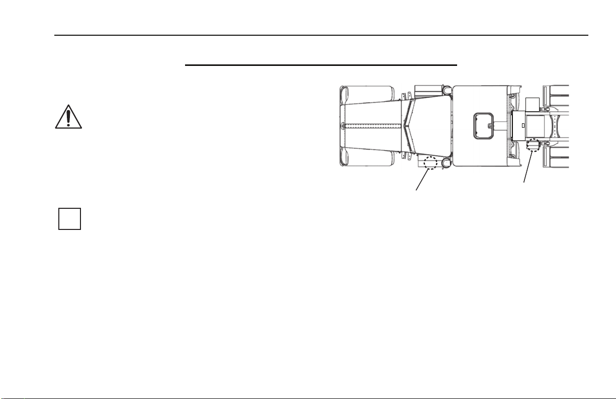
Figure -135
Fuel Filter
Figure -136
Driver Side
Fuel Tank
PB00031
The fuel filter is located along the frame above the driver
side fuel tank. The fuel filter should be inspected every 12
months. Check the filter for debris, sediment or water.
Replace if any is found.
Figure -137
NOTE: Do not substitute the Webasto supplied
fuel filter with a non-Webasto replacement filter.
i
Irregular heater operation may result if a
non-Webasto filter is used.
– 40 – Y53-6017 R(09/07)
Page 43

PART 4: TROUBLESHOOTING
Figure -138
Figure -139
Concern Possible Cause Remedy
Parked truck will not get
cool.
Parked truck will not stay
cool for up to 10 hours.
Parked truck will not get
warm.
Storage Cooler not
charged.
Lack of cool air out of
vents.
Storage Cooler is
depleting too quickly.
Lack of hot air out of lower
heater vent.
PART 4: TROUBLESHOOTING
1. Make sure Charge/Enable dash switch is in the ON position.
2. Make sure the Inverter/Charger Switch is in the ON position.
3. Make sure the circuit breaker in the Circuit Breaker Box is not tripped. Reset if necessary.
4. Air conditioning component service/refrigerant level check.
(Please note, if outside temperature is below 55°F, compressor will not turn on.)
1. Make sure blower is in the ON position.
2. Make sure air conditioning mode is selected.
3. Make sure temperature control is set in the blue zone.
4. Service fresh air/recirculation filter.
5. Check coolant level.
6. Component service.
7. Cab was not pre-cooled.
1. Make sure temperature control is set in the green zone.
2. Make sure sleeper pass-through curtain is closed and all window coverings are installed.
1. Make sure heating mode is selected.
2. Make sure temperature control is set in the red zone.
3. Check for heater diagnostic blink codes at the heater mode selection LED.
4. Make sure heater inlet in tool compartment is not blocked.
5. Make sure fuel and exhaust lines are not blocked.
6. Component service.
R(09/07) Y53-6017 – 41 –
Page 44

Concern Possible Cause Remedy
Sleeper AC electrical
outlets not working.
Cannot run cab/sleeper
DC loads.
Cannot start truck. Voltage at ComfortClass
No power to sleeper AC
electrical outlets.
Not enough power
available for cab/
sleeper DC loads.
System Batteries is too
low (below 9.5 Volts).
Not enough cranking
power from starting
batteries.
1. Make sure battery disconnect switch on ComfortClass System Battery Box is in the ON
position.
2. Make sure Inverter/Charger Switch is in the ON position.
3. Make sure the circuit breaker in the Circuit Breaker Box is not tripped. Reset if necessary.
4. Make sure GFCI in the Circuit Breaker Box is not tripped. Reset if necessary.
5. Component service.
1. Make sure battery disconnects are in the ON position.
2. Make sure LVD is not tripped. (To reset, ComfortClass System Battery voltage must be
brought up to 13.2 Volts by starting the truck or using Shore Power electrical supply).
3. Check ComfortClass System Battery voltage. If voltage is below 11 Volts, charge the
ComfortClass System Batteries.
1. Make sure both battery disconnects are in the ON position.
2. Hook up to Shore Power electrical supply to charge ComfortClass System Batteries or
attach battery charger to charging terminals.
1. Make sure both battery disconnects are in the ON position.
2. Check starting battery voltage. If voltage is below 12 Volts (check at starter using voltmeter),
charge starting batteries with external battery charger.
3. If starting battery voltage continues to discharge, replace starting batteries and/or have an
authorized repair facility service the vehicle.
PART 4: TROUBLESHOOTING
– 42 – Y53-6017 R(09/07)
 Loading...