

Page 1

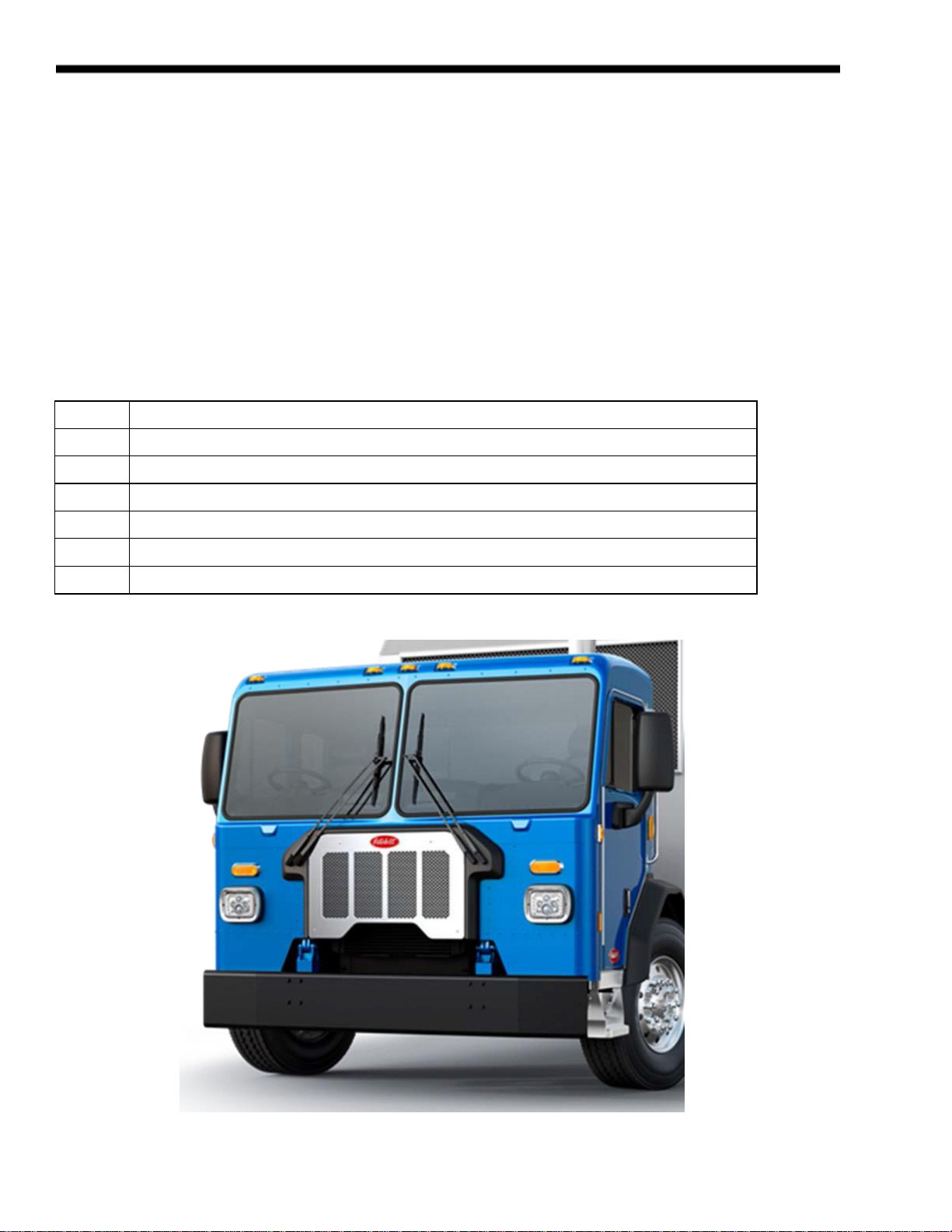
Model 520
Body Builder Manual
2019
Release Date 7/30/19
Page 2

This page intentionally left blank
Page 3

BODY BUILDER MANUAL CONTENTS
SECTION 1: INTRODUCTION 1-1
SECTION 2: SAFETY AND COMPLIANCE
SAFETY SIGNALS 2-1
FEDERAL MOTOR VEHICLE SAFETY STANDARDS AND COMPLIANCE 2-2
NOISE AND EMISSIONS REQUIREMENTS 2-3
FUEL SYSTEM 2-4
COMPRESSED AIR SYSTEM 2-4
EXHAUST AND EXHAUST AFTER-TREATMENT SYSTEM 2-5
COOLING SYSTEM 2-6
AIR INTAKE SYSTEM 2-6
CHARGE AIR COOLER SYSTEM 2-6
SECTION 3: DIMENSIONS
INTRODUCTION
3-1
ABBREVIATIONS
3-1
OVERALL DIMENSIONS 3-2
FRAME RAILS 3-9
FRAME HEIGHT CHARTS 3-11
REAR SUSPENSION LAYOUTS 3-18
Reyco 79KB Single 3-19
Reyco 102AR Single 3-20
Neway ADZ252 3-21
Neway ADZ369/378 3-22
Peterbilt Air Leaf 3-23
Peterbilt Air Trac Single 3-24
Peterbilt Air Trac Tandem 3-25
Peterbilt Air Trac Tri-Drive 3-26
Peterbilt Low Air Leaf 3-27
Chalmers 854 3-28
Hendrickson HMX 3-29
Hendrickson RT/RTE 3-30
Hendrickson HN 3-31
Hendrickson R 3-32
Hendrickson RS 3-33
PUSHER AND TAG LAYOUTS 3-34
Hendrickson
3-34
Watson-Chalin
3-38
EXHAUST HEIGHT CALCULATIONS 3-42
GROUND CLEARANCE CALCULATIONS 3-43
OVERALL CAB HEIGHT CALCULATIONS 3-44
FRAME COMPONENTS 3-45
Fuel Tanks 3-45
EXHAUST SYSTEM 3-46
SECTION 4: BODY MOUNTING
INTRODUCTION
4-1
FRAME RAILS 4-1
CRITICAL CLEARANCES 4-2
BODY MOUNTING USING BRACKETS 4-3
Brackets
4-4
Mounting Holes 4-5
Frame Drilling 4-6
Peterbilt Motors Company ii
Page 4

BODY MOUNTING USING U–BOLTS 4-7
Rear Body Mount 4-9
SECTION 5: FRAME MODIFICATIONS
INTRODUCTION 5-1
DRILLING RAILS 5-1
MODIFYING FRAME LENGTH 5-2
CHANGING WHEELBASE 5-2
CROSSMEMBERS 5-3
TORQUE REQUIREMENTS 5-4
SECTION 6: ELECTRICAL 520 FAMILY
CONTROL UNIT IDENTIFICATION 6-1
Functional Description-Cab Electronic Control Unit (CECU) 6-1
HOW MULTIPLEXED INSTRUMENTS WORK 6-2
CECU Architecture 6-2
Power On Self-Test 6-3
ELECTRICAL INTERFACE 6-4
Cab Harness 6-4
Chassis Harness 6-9
Body Builder Harness Extensions 6-10
Optional Body Builder PTO Module 6-10
J1939 6-13
Guidelines - J1939 Circuit Requirements 6-13
J1939 Access 6-13
J1939 Access Procedures 6-13
SECTION 7: PTO SECTION
INTRODUCTION 7-1
TRANSMISSION MOUTED PTO – GENERAL 7-1
Manual Transmission 7-1
Automatic Transmission 7-2
Installation Clearances 7-2
FRONT ENGINE PTO 7-3
REAR ENGINE PTO 7-4
PTO INSTALLATIONS 7-5
REMOTE PTO CONTROL (12 PIN CONNECTOR) 7-6
Cummins Remote PTO Operation 7-6
INSTALLATION OF PTO MODEL 7-7
Chelsea 890 7-7
OPTIONAL PTO FUNCTION MODULE 7-8
APPENDICES:
REVISION LOG A1
Peterbilt Motors Company iii
Page 5

SECTION 1 INTRODUCTION
The Peterbilt 520 Body Builder Manual was designed to provide body builders with a comprehensive information set to
guide the body planning and installation process. Use this information when installing bodies or other associated
equipment.
This manual contains appropriate dimensional information, guidelines for mounting bodies, modifying frames, electrical
wiring information, and other information useful in the body installation process.
The Peterbilt 520 Body Builder Manual can be very useful when specifying a vehicle, particularly when the body builder is
involved in the vehicle definition and ordering process. Information in this manual will help reduce overall costs through
optimized integration of the body installation with vehicle selection. Early in the process, professional body builders can
often contribute valuable information that reduces the ultimate cost of the body installation.
In the interest of continuing product development, Peterbilt reserves the right to change specifications or products at any
time without prior notice. It is the responsibility of the user to ensure that he is working with the latest released information.
Check Peterbilt.com for the latest released version.
If you require additional information or reference materials, please contact your local Peterbilt dealer.
Peterbilt Motors Company 1-1
Page 6

This page intentionally left blank
Page 7

2
SAFETY AND COMPLIANCE
SECTION 2 SAFETY AND COMPLIANCE
SAFETY SIGNALS
We’ve put a number of alerting messages in this book. Please read and follow them. They are there for your
protection and information. These alerting messages can help you avoid injury to yourself or others and help
prevent costly dam- age to the vehicle.
Key symbols and “signal words” are used to indicate what kind of message is going to follow. Pay special attention
to comments prefaced by “WARNING”, “CAUTION”, and “NOTE.” Please don’t ignore any of these alerts.
Warnings, cautions, and notes
When you see this word and symbol, the message that follows is especially vital. It signals a
potentially hazardous situation which, if not avoided, could result in death or serious injury.
This message will tell you what the hazard is, what can happen if you don’t heed the warning,
and how to avoid it.
Example:
WARNING! Be sure to use a circuit breaker designed to meet liftgate amperage requirements. An
incorrectly specified circuit breaker could result in an electrical overload or fire situation. Follow the
liftgate installation instructions and use a circuit breaker with the recommended capacity.
CAUTION
Signals a potentially hazardous situation which, if not avoided, could result in minor or
moderate injury or damage to the vehicle.
Example:
CAUTION: Never use a torch to make a hole in the rail. Use the appropriate drill bit.
Provides general information: for example, the note could warn you on how to avoid damaging
your vehicle or how to drive the vehicle more efficiently.
Example:
Note: Be sure to provide maintenance access to the battery box and fuel tank fill neck.
Please take the time to read these messages when you see them, and remember:
WARNING
Indicates a potentially hazardous situation which, if not avoided, could result in death or serious injury.
CAUTION
Signals a potentially hazardous situation which, if not avoided, could result in minor or moderate
injury or damage to the vehicle.
NOTE
Useful information that is related to the topic being discussed.
WARNING
NOTE
Page 8

FEDERAL MOTOR VEHICLE SAFETY STANDARDS AND COMPLIANCE
As an Original Equipment Manufacturer, Peterbilt Motors Company. ensures that our products comply with all applicable
U.S.
or Canadian Federal Motor Vehicle Safety Standards. However, the fact that this vehicle has no fifth wheel and that a
Body Builder (Intermediate or Final Stage Manufacturer) will be doing additional modifications means that the vehicle was
incomplete when it left the build plant.
Incomplete Vehicle Certification
An Incomplete Vehicle Document is shipped with the vehicle, certifying that the vehicle is not complete. See Figure 2–1.
In addition, affixed to the driver’s side door frame or edge is an Incomplete Vehicle Certification label. See Figure 2–2.
NOTE
These documents list the U.S. or Canadian Federal Motor Vehicle Safety Standard regulations that the
vehicle complied with when it left the build plant. You should be aware that if you add, modify or alter any
of the components or systems covered by these regulations, it is your responsibility as the Intermediate or
Final Stage Manufacturer to ensure that the complete vehicle is in compliance with the particular
regulations upon completion of the modifications.
FIGURE 2-1. Incomplete Vehicle Certification Document
Tire, Rim and
Weight Rating
Data label
Safety Mark (Canadian
Registry Only)
Incomplete Vehicle
Certification Label
U.S. EPA Noise Label (U.S. registered vehicles only)
Final Stage Manufacturer
Label to be installed by
Final Stage Manufacturer
Chassis Serial
Number
Vehicle Emission Control
Information Label
Major Components and
Weights Label
FIGURE 2-2. Locations of Certification Labels - Driver’s Door and Frame
As the Intermediate or Final Stage Manufacturer, you should retain the Incomplete Vehicle Document for your records. In
addition, you should record and retain the manufacturer and serial number of the tires on the vehicle. Upon completion of
the vehicle (installation of the body and any other modifications), you should affix your certification label to the vehicle as
required by Federal law. This tag identifies you as the “Intermediate or Final Stage Manufacturer” and certifies that the
vehicle complies with Federal Motor Vehicle Safety Standards. (See Figure 2–2.) Be advised that regulations affecting the
intermediate and final stage manufacturer may change without notice. Ensure you are referencing the most updated copy
of the regulation during the certification and documentation processes.
In part, if the final stage manufacturer can complete and certify the vehicle within the instruction in the incomplete vehicle
document (IVD) the certification label would need a statement that reads, “This vehicle has been completed in accordance
with the prior manufacturers‚ IVD where applicable. This vehicle conforms to all applicable Federal Motor Vehicle Safety
Standards [and Bumper and Theft Prevention Standards if applicable] in effect in (month, year).”
However, if the vehicle cannot be completed and certified with in the guidance provided in the IVD, the final stage
manufacturer must ensure the vehicle conforms to all applicable Federal Motor Vehicle Safety Standards (FMVSS). The
final stage manufactures certification label would need a statement that reads, “This vehicle conforms to all applicable
Federal Motor Vehicle Safety Standards [and Bumper and Theft Prevention Standards if applicable] in effect in (month,
Peterbilt Motors Company 2-2
SAFETY AND COMPLIANCE
2
Page 9

2
SAFETY AND COMPLIANCE
2-3
Peterbilt Motors Company
year).These statements are just part of the changes to the new certification regulation. Please refer to the Feb 15, 2005
final rule for all of the details related to this regulation. You can contact NTEA Technical Services Department at 1-800441- NTEA for a copy of the final rule (DocID 101760).
For Canadian final stage manufacturers see:
http://www.gazette.gc.ca/index-eng.html;
and http://www.tc.gc.ca/eng/acts-regulations/menu.htm for
the regulations.
Or contact:
Transport
Canada
Tower C, Place de Ville, 330 Sparks Street
Ottawa, Ontario K1A
0N5 (613) 990-2309
TTY: 1-888-675-6863
Noise and Emissions Requirements
NOTE
This truck may be equipped with specific emissions control components/systems* in order to
meet applicable Federal and California noise and exhaust emissions requirements. Tampering with
these emissions control components/systems* is against the rules that are established by the
U.S Code of Federal Regulations, Environment Canada Regulations and California Air Resources
Board (CARB). These emissions control components/systems* may only be replaced with original
equipment parts.
Additionally, most vehicles in North America will be equipped with a Greenhouse Gas (GHG)
“Vehicle Emission Control Information” door label indicating its certified configuration. The vehicle
components listed on this label are considered emission control devices.
Modifying (i.e. altering, substituting, relocating) any of the emissions control components/systems
defined above will affect the noise and emissions performance/certification. Modifications that
alter the overall shape and aerodynamic performance of a tractor will also affect the emission
certification. If modifications are required, they must first be approved by the manufacturer.
Unapproved modifications could negatively affect emissions performance/certification. There is no
guarantee that proposed modifications will be approved.
Tires may be substituted provided the new tires possess a Coefficient of rolling resistance (Crr)
equal to or lower than Crr of the original tires. Consult with your tire supplier(s) for appropriate
replacement tires.
Contact the engine manufacturer for any requirements and restrictions prior to any modifications.
•
For Cummins Contact 1-800-DIESELS or your local Cummins distributor. Reference AEB 21.102.
It is possible to relocate the DEF tank; however the relocation requirements need to be followed. Any variances from the
relocation requirements may cause the emissions control components/systems to operate improperly potentially resulting
in engine de-rate.
Page 10

NOTE
All 2017 engine emissions certified vehicles will be equipped with an On-Board Diagnostics (OBD)
system. The OBD system is designed to detect malfunctions of any engine or vehicle
component that may increase exhaust emissions or interfere with the proper performance of the
OBD system itself All diesel engines will be equipped with an On-Board Diagnostics (OBD)
system. The OBD system consists of computer program on one or more of the vehicle’s Electronic
Control Units (ECUs). This program uses information from the control system and from additional
sensors to detect malfunctions. When a malfunction is detected, information is stored in the
ECU(s) for diagnostic purposes. A Malfunction Indicator Light (MIL) is illuminated in the dash to
alert the driver of the need for service of an emission-related component or system.
To ensure compliance to emissions regulations, the final configuration of certain features of the completed vehicle
must meet specific requirements. This section describes requirements relevant for only the most common or critical
modifications done by body builders. For a complete description of acceptable modifications, see the application
guidance available from the manufacturer of the engine installed in the chassis.
Fuel System
The following are highlights of some of the more common or critical aspects of this system.
The overall system restriction may not exceed the restriction limitations set forth by the engine manufacturer for both
supply and return.
•
Ensure that fuel lines are not pinched or can potentially be damaged when installed between body
and frame
•
Fuel lines must be routed and secured without dips or sags
•
There must be easy access to filter(s) and fill cap
•
The tank vent may not obstructed
•
Added accessories (heaters, generators) cannot introduce air into system
•
Fuel tank must be located so that the full level is not above cylinder head
•
“Ultra-Low Sulfur Fuel Only” labels must be present on the dash and fuel fill
•
Modification of the pressure side secondary filter and plumbing is not allowed without engine
manufacturer approval
•
Body installation of fuel tank or routing of lines must not cause significant increase in fuel temperature
•
Fuel hoses shall meet or exceed OEM supplied hose material construction specifications
Compressed Air System
The following are highlights of some of the more common or critical aspects of this system.
•
Air system modification must meet applicable FMVSS regulations
•
Compressed Air tank may not be modified (exception – addition or removal of fittings or relocation of the
tank)
•
Added devices or bodywork may not interfere with or rub air lines
Peterbilt Motors Company 2-4
SAFETY AND COMPLIANCE
2
Page 11

2
SAFETY AND COMPLIANCE
2-5
Peterbilt Motors Company
•
Air supply to the engine doser may not be restricted or disconnected
•
Air lines should be routed, protected from heat, and properly secured to prevent damage
from other components
•
Care should be taken so that air lines do not rub against other components
•
Care should be taken to protect the air system from heat sources
Exhaust and Exhaust After-treatment System
The following are highlights of some of the more common or critical aspects of this system.
•
The following after-treatment and exhaust system components may not be modified:
•
DPF assembly
•
SCR Catalyst assembly
•
Exhaust pipes between the engine and after-treatment devices (DPF, SCR Catalyst) and between
after-treatment devices
•
NOx Sensors
•
PM Sensor
•
The following modifications may only be done within the guidelines of the “DEF System Relocation Guide.”
•
Modifications to Diesel Exhaust Fluid (DEF) throttle, suction, or pressure lines
•
Modification or relocation of the DEF tank
•
Modification of coolant lines to and from the DEF tank
•
All DEF and coolant lines should be routed, protected, and properly secured to prevent damage during
vehicle operation or other components
•
If relocation of the DCU or ACM is necessary, use existing frame brackets and mount inside of frame
flanges where necessary. Do not extend the harnesses
•
The DPF, the SCR catalyst, or their mounting may not be modified
•
The NOx sensor may not be relocated or altered in any way; this includes re-clocking the
aftertreatement canister or reorienting the sensor(s)
•
Exhaust pipes used for tailpipes/stacks must be properly sized, and must prevent water from entering
•
Ensure adequate clearance between the exhaust and body panels, hoses, and wire harnesses
•
The body in the vicinity of the DPF must be able to withstand temperatures up to 400°C (750°F)
•
Do not add thermal insulation to the external surface of the DPF
•
The SCR water drain hole may not be blocked
•
Allow adequate clearance (25mm (1 inch)) for servicing the DPF sensors, wiring, and clamped joints
•
Drainage may not come in contact with the DPF, SCR catalyst, sensors or wiring
Page 12

•
Allow sufficient clearance for removing sensors from DPF. Thermistors require four inches. Other
sensors require one inch
•
Wiring should be routed, protected from heat, and properly secured to prevent damage
from other components
•
The exhaust system from an auxiliary power unit (APU) must not be connected to any part of the
vehicle after-treatment system or vehicle tail pipe.
Cooling System
The following are highlights of some of the more common or critical aspects of this system.
•
Modifications to the design or locations of fill or vent lines, heater or defroster core, and surge tank are
not recommended
•
Additional accessories plumbed into the engine cooling system are not permitted, at the risk of voiding
vehicle warranty
•
Coolant level sensor tampering will void warranty
•
When installing auxiliary equipment in front of the vehicle, or additional heat exchangers, ensure
that adequate air flow is available to the vehicle cooling system. Refer to engine manufacturer
application guide- lines for further detail
•
When installing FEPTO drivelines, the lower radiator anti-recirculation seal must be retained with
FEPTO driveline clearance modification only
•
Changes made to cooling fan circuit and controls are not allowed, with the exception of AC
minimum fan on time parameter
•
See owner’s manual for appropriate winter front usage
Air Intake System
The following are highlights of some of the more common or critical aspects of this system.
•
The air intake screen may not be blocked, either fully or partially
•
Modification to the air intake system may not restrict airflow. For example, pipe diameter may not be reduced
•
All sensors must be retained in existing locations
•
To retain system seal, proper clamp torque must be used. Refer to service manual for proper clamp torque
Charge Air Cooler System
The following are highlights of some of the more common or critical aspects of this system.
•
The Charge Air Cooler may not be modified
•
The installation of engine overspeed shutdown devices must not introduce restriction in the intake system
•
All plumbing associated with the charge air cooler may not be modified
Peterbilt Motors Company 2-6
SAFETY AND COMPLIANCE
2
Page 13
SECTION 3 DIMENSIONS
INTRODUCTION
This section has been designed to provide enough information to successfully layout a chassis in the body planning
process. All dimensions are inches unless otherwise noted. Optional equipment may not be depicted. Please contact
your local Peterbilt dealer if more dimensional information is desired.
ABBREVIATIONS
Throughout this section and in other sections as well, abbreviations are used to describe certain characteristics on your
vehicle. Table 3-1 below lists the abbreviated terms used.
TABLE 3-1. Abbreviations Used
BFA
Bumper to front axle
BOC
Back of cab
CA
Cab to axle. Measured from the back of the cab to the centerline of the rear axle(s).
EOF
Frame rail overhang behind rear axle--measured from the centerline of tandems
FAX
Front axle
FOF
Front of frame
WB
Wheelbase
Page 14
3
DIMENSIONS
Peterbilt Motors Company
3- 2
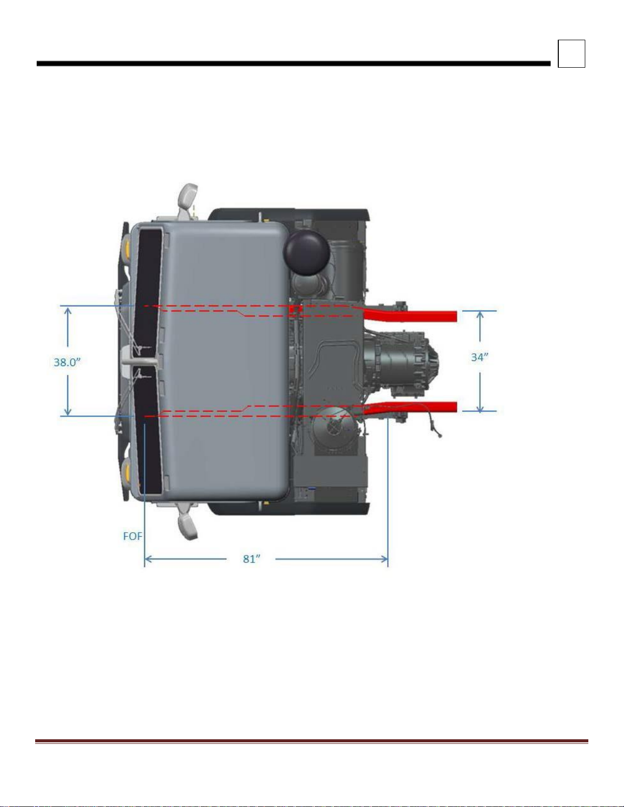
OVERALL DIMENSIONS
This section includes drawings and charts of the Peterbilt Model 520.
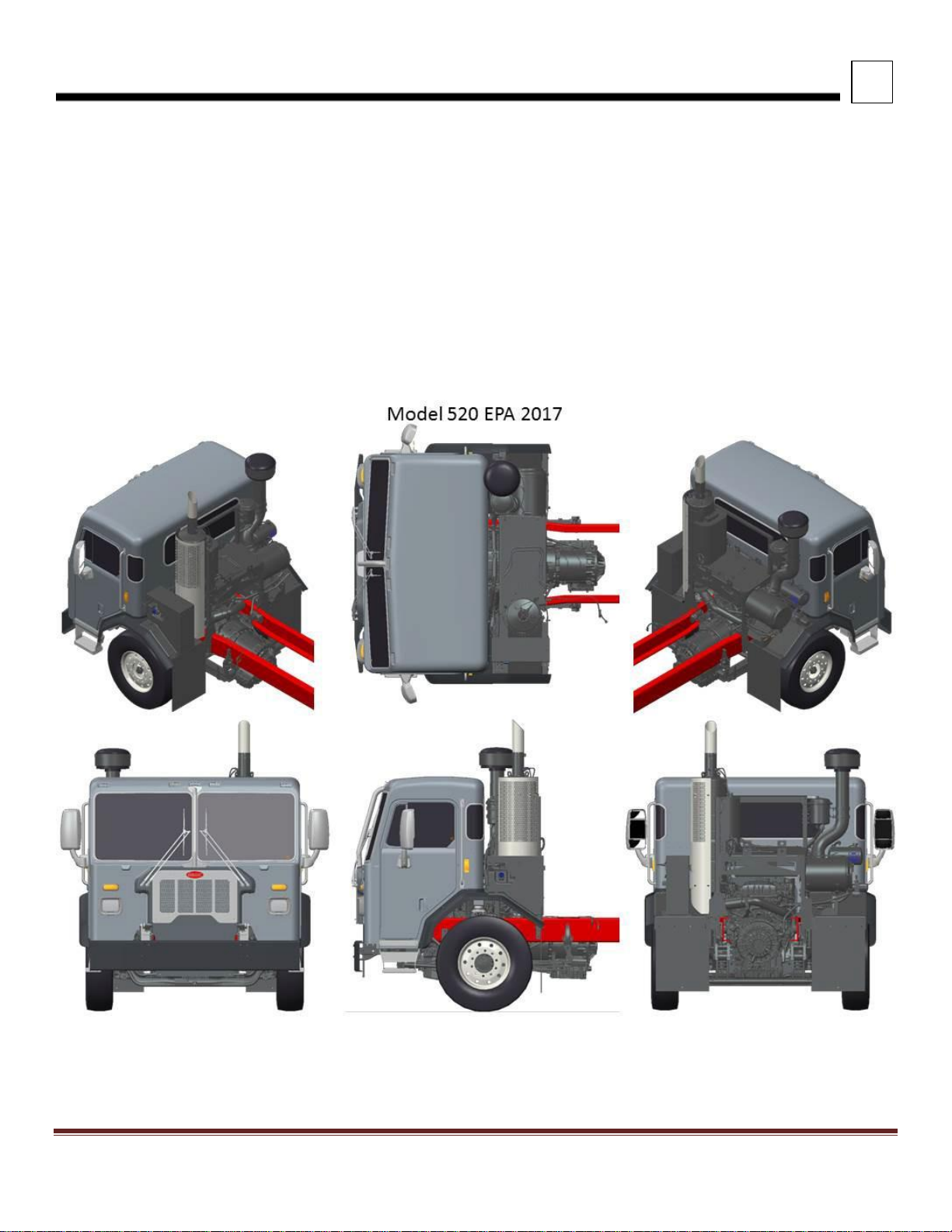
On the pages that follow, detail drawings show particular views of the vehicle; all dimensions are in inches (in). They
illustrate important measurements critical to designing bodies of all types. See the “Contents” at the beginning of the
manual to locate the drawing that you need.
All heights are given from the bottom of the frame rail.
Note that the Aftertreatment mounting is almost identical other than the use of a DEF tank (for diesels) and different
canister/catalyst but both use the same stanchions for mounting BOC.
FIGURE 3-1. Various Views of the Model 520
Page 15
3
DIMENSIONS
Peterbilt Motors Company
3- 3
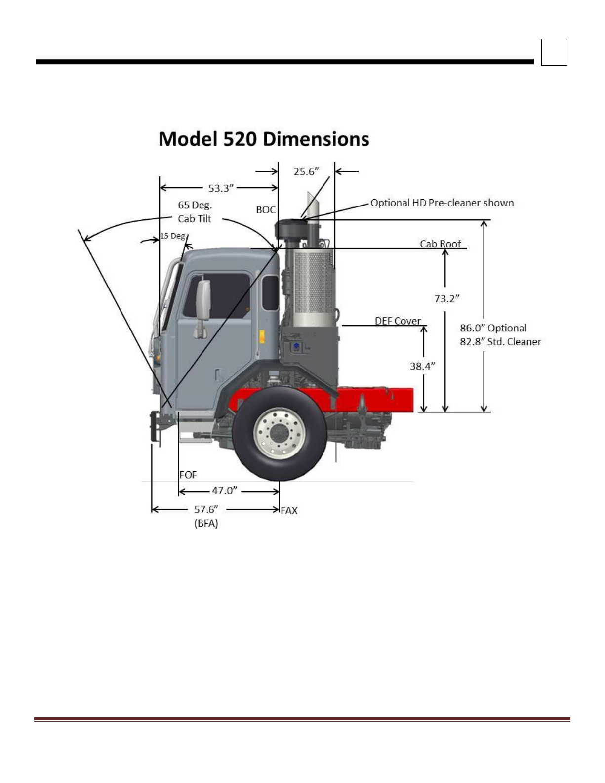
EXTERIOR DIMENSIONS
FIGURE 3-2. 520 Cab Dimensions
Notes:
1. Shown with optional HD Air intake Pre-Cleaner
2. Shown with optional front cab guard
3. Door dimension is 33.4”W x 61”H
4. Diesel truck shown, but Natural Gas has same BOC dimension for Aftertreatement.
Page 16
3
DIMENSIONS
Peterbilt Motors Company
3- 4
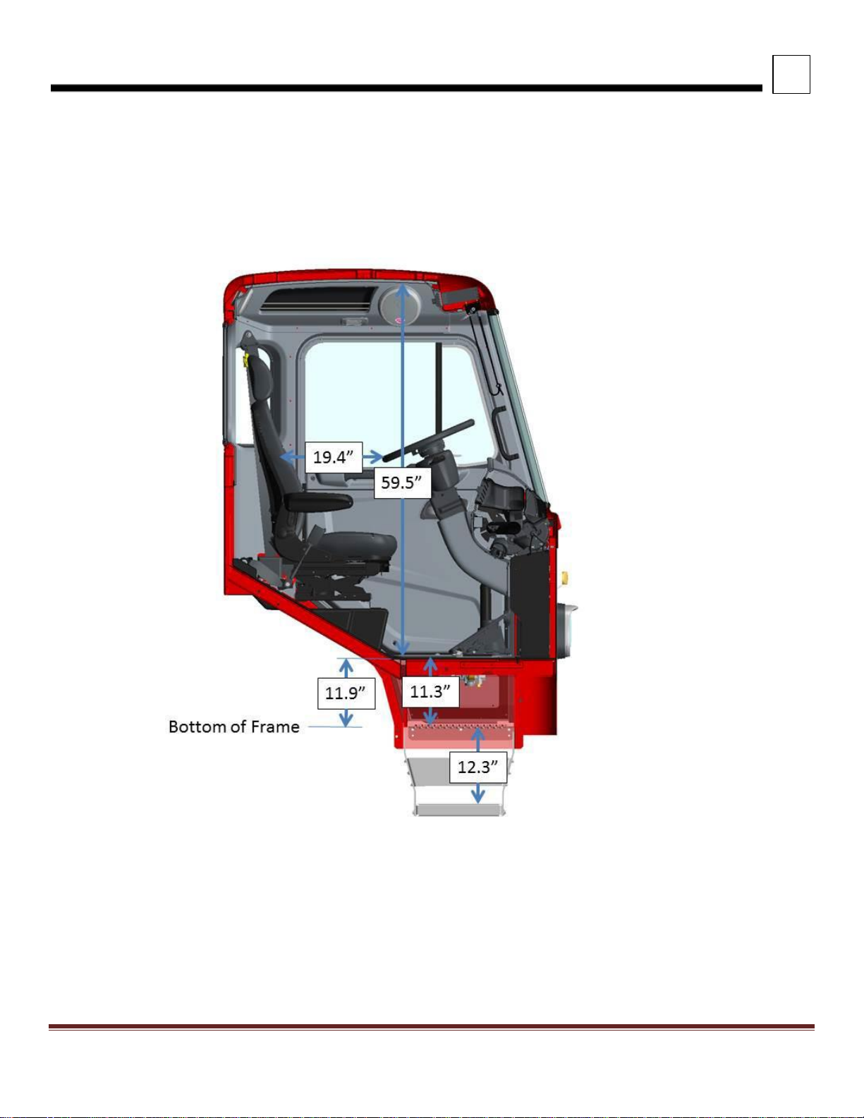
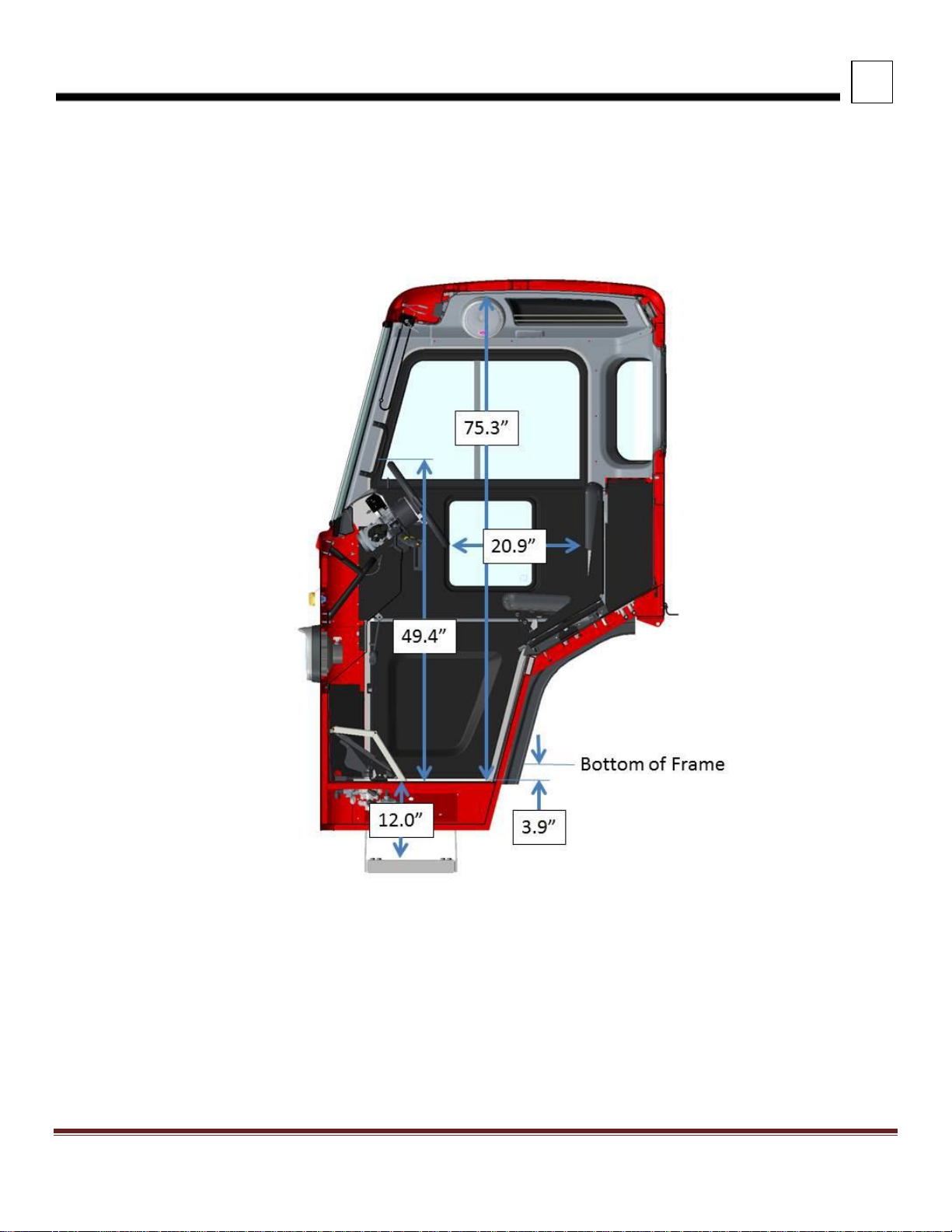
INTERIOR DIMENSIONS
FIGURE 3-3. View Looking Through Cab to the Driver’s Side (LH Steer)
Page 17
3
DIMENSIONS
Peterbilt Motors Company
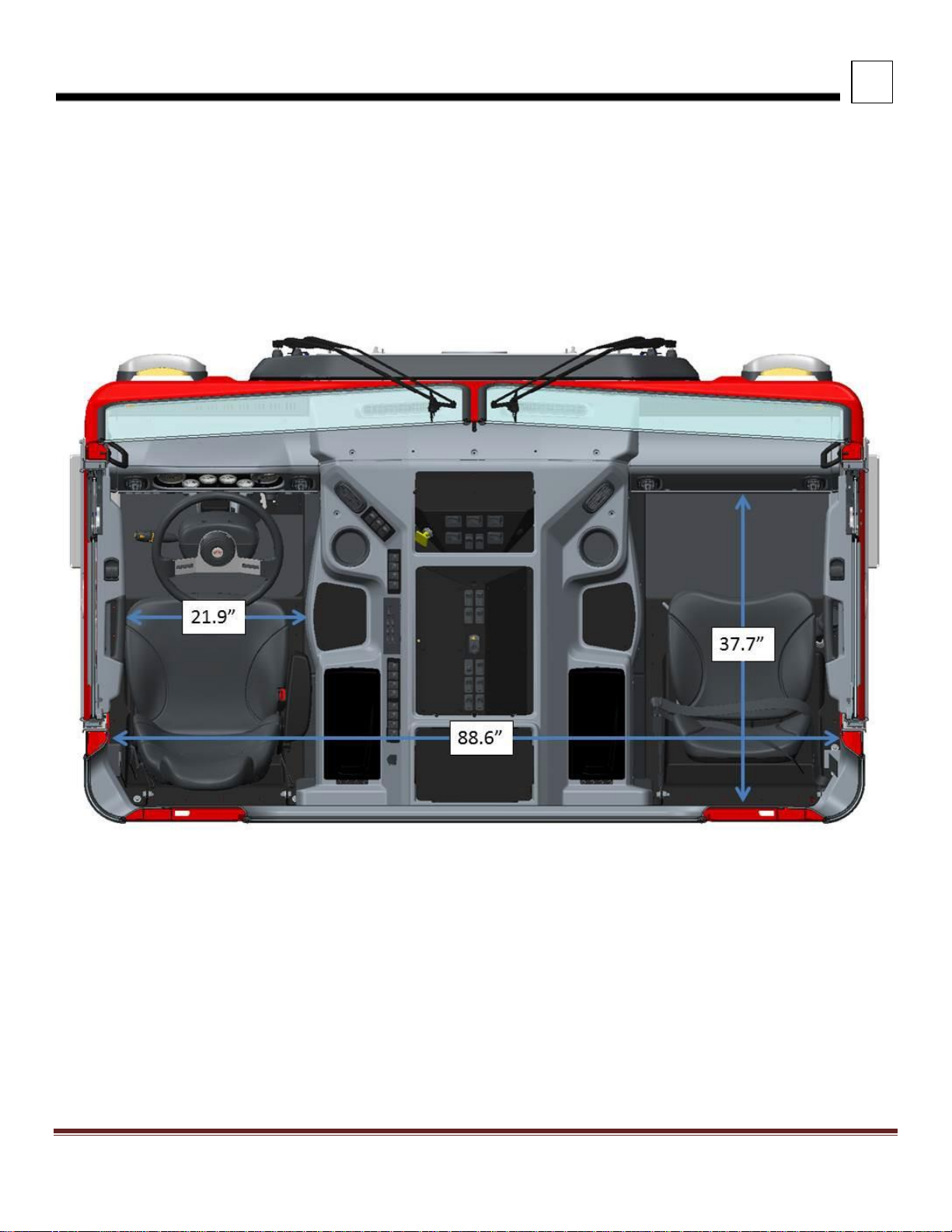
3- 5
INTERIOR DIMENSIONS
FIGURE 3-4. View Looking Through the Cab At The RH Drive Standup Version
Page 18
3
DIMENSIONS
Peterbilt Motors Company
3- 6
INTERIOR DIMENSIONS
FIGURE 3-5. Top View of LH Steer Model
Page 19
3
DIMENSIONS
Peterbilt Motors Company
3- 7
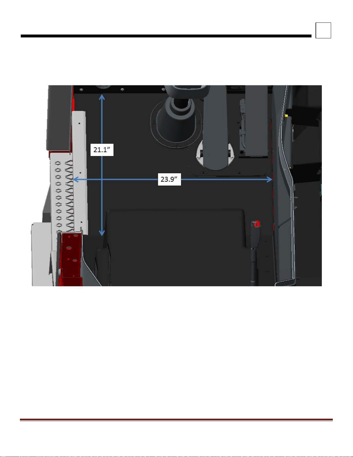
INTERIOR DIMENSIONS
FIGURE 3-6. Floor Dimensions for LH Floor
Page 20
3
DIMENSIONS
Peterbilt Motors Company
3- 8
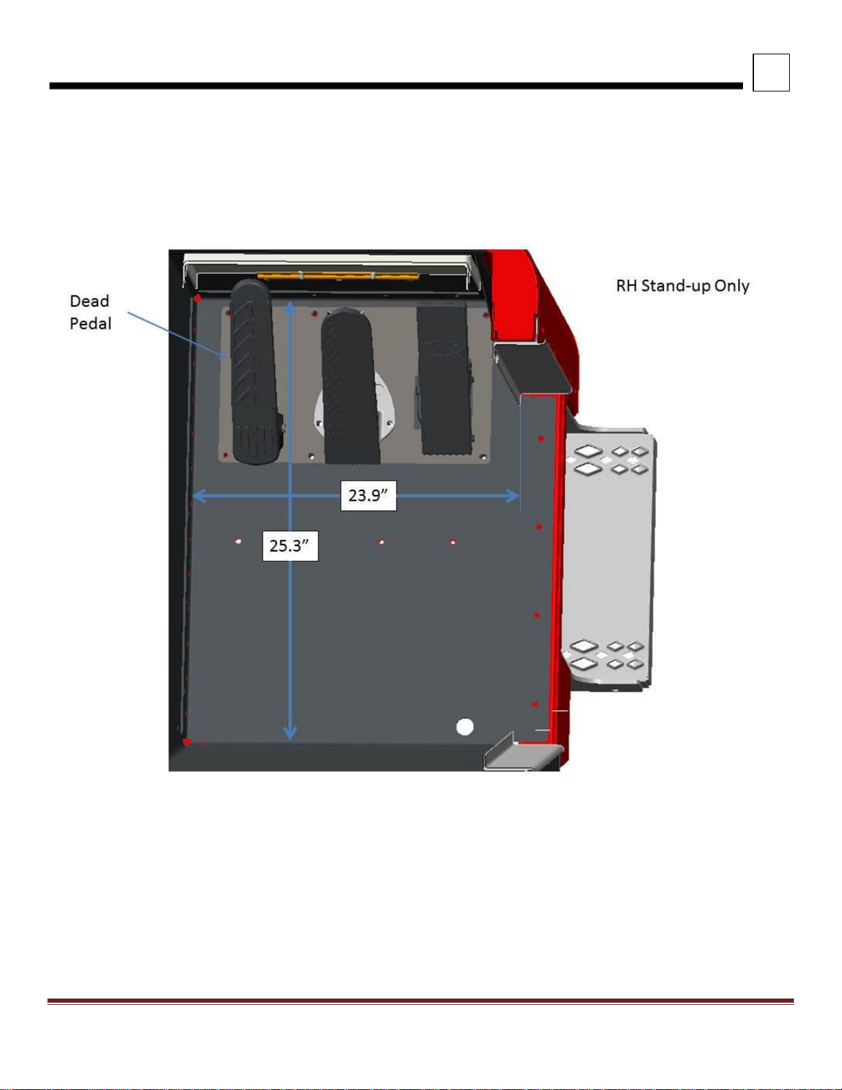
INTERIOR DIMENSIONS
FIGURE 3-7. Passenger Floor RH Stand Up
Page 21
3
DIMENSIONS
Peterbilt Motors Company
3- 9
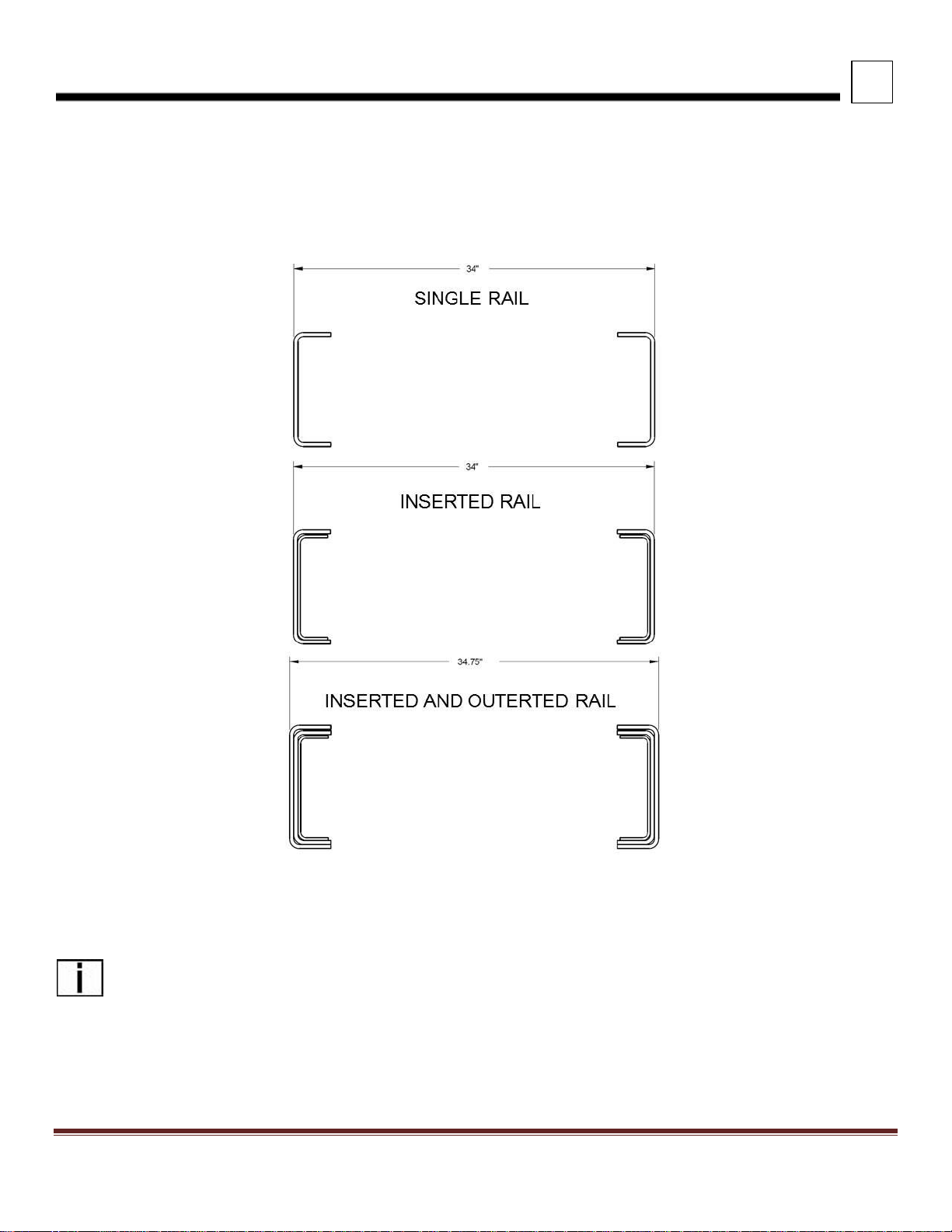
FRAME RAILS
Frame rail configurations are shown in Figure 3-8. The under cab area of the 520 frame rails are splayed as shown in
Figure 3-9. Frame height, flange and structural values can be found in the Body Mounting Section.
FIGURE 3-8. Frame Rail Configurations
NOTE: The outserted frame section does not extend through the rear suspension area. The outserted frame
section does not extend through the splayed area.
Page 22
3
DIMENSIONS
Peterbilt Motors Company
3- 10
FRAME RAILS
FIGURE 3-9. Model 520 Frame Rail
Page 23
3
DIMENSIONS
Peterbilt Motors Company
3- 11
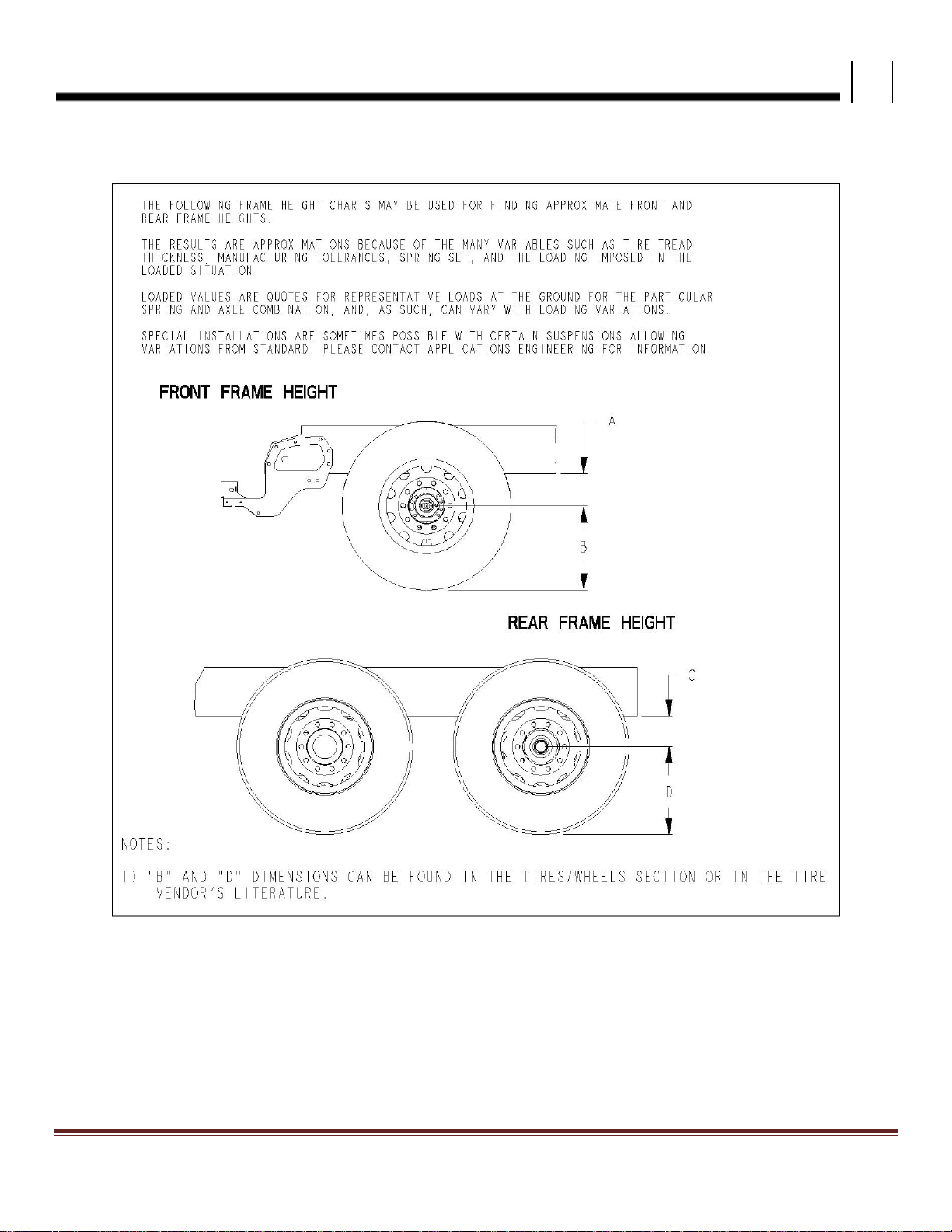
FRAME HEIGHT CHARTS
FIGURE 3-4. Frame Height
Page 24
3
DIMENSIONS
Peterbilt Motors Company
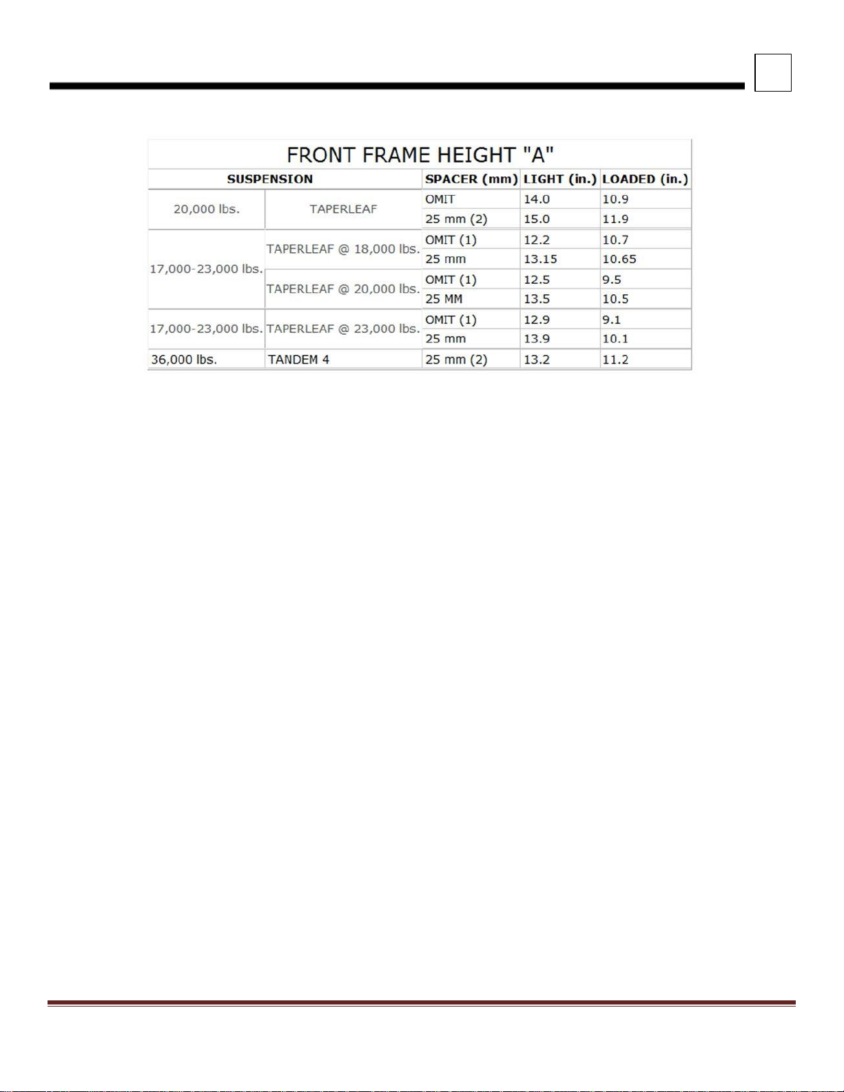
3- 12
TABLE 3-2. Front Frame Height “A” – 520
NOTES:
1)
Omit spacer block standard.
2)
25mm spacer block standard and required.
3)
Standard 3-1/2" drop axle heights shown, for 5" drop axles, subtract an additional 1-1/2".
4)
Spacer blocks are used by Engineering to obtain level frame and are not options.
5)
"A" dimension shown is to bottom of frame rail. Add frame rail height dimension for frame height.
Page 25

3
DIMENSIONS
Peterbilt Motors Company
3- 13
REAR FRAME HEIGHTS "C"
TABLE 3-3. Single Drive Suspension Heights
Suspension
Rating
Version
Light
Height
Laden
Height
LOW AIR LEAF
21,000 lbs.
Standard
6.8
6.5
AIR TRAC
20,000 lbs.
Standard
11.4
11.0
23,000 lbs.
Standard
11.4
11.0
REYCO 79KB
20,000 lbs.
Taper-leaf (3.38"
saddle)
9.4
11.8
21,000 lbs.
Taper-leaf (1.38"
saddle)
7.4
9.8
23,000 lbs.
Multi-leaf (1.38"
saddle)
8.8
11.6
26,000 lbs.
Multi-leaf (1.38"
saddle)
9.2
11.8
28,000 lbs.
Multi-leaf (1.38"
saddle)
9.6
12.3
31,000 lbs.
Multi-leaf (1.38"
saddle)
10.7
13.3
REYCO 102
23K-29K lbs.
4.38 saddle
12.0
10.2
23K-29K lbs.
4.63 saddle
12.2
10.4
29,000 lbs.
3.50 saddle
11.7
10.0
31,000 lbs.
3.50 saddle
12.2
10.5
31,000 lbs.
4.38 saddle
12.5
10.7
31,000 lbs.
4.63 saddle
12.7
10.9
REYCO 102AR (AIR)
17K -23K
Standard
9.3
9.3
Low
8.3
8.3
Page 26

3
DIMENSIONS
Peterbilt Motors Company
3- 14
TABLE 3-4. Tandem Drive Peterbilt Suspension Heights
Suspension
Rating
Version
Light
Height
Laden
Height
AIR LEAF
38,000 lbs.
12.0
11.7
LOW AIR LEAF
40,000 lbs.
8.8
8.5
FLEX AIR
38,000 lbs.
8.8
8.5
LOW-LOW AIR
LEAF
40,000 lbs.
6.8
6.5
AIR TRAC
40K-46K lbs.
11.4
11.0
QUADRAFLEX
38,000 lbs.
Taper-leaf
10.6
8.7
TABLE 3-5. Tandem Drive Neway Suspension Heights
Suspension
Rating
Version
Light
Height
Laden
Height
NEWAY AD
52,000 lbs.
10.0
10.0
NEWAY ADZ
46K-52K lbs.
10.0
10.0
TABLE 3-6. Tandem Drive Reyco Suspension Heights
Suspension
Rating
Version
Light
Height
Laden
Height
REYCO 102
MULTILEAF
40,000 lbs.
1.75 saddle (STD)
11.7
9.8
1.38 saddle
10.2
8.3
3.38 saddle
13.4
11.5
44,000 lbs.
1.75 saddle (STD)
11.7
9.8
1.38 saddle
11.5
9.7
REYCO 102AR
(AIR)
34K-40K
STD LOW
8.3
8.3
Page 27

3
DIMENSIONS
Peterbilt Motors Company
3- 15
TABLE 3-7. Tandem Drive Chalmers Suspension Heights
Suspension
Rating
Version
Light
Height
Laden
Height
CHALMERS 854 &
860
40,000 lbs.
LOW
11.1
8.9
HIGH
12.4
10.2
X-HIGH
14.5
12.2
XX-HIGH
17.2
14.9
CHALMERS 854 &
860
46,000 lbs.
LOW
11.3
8.9
HIGH
12.5
10.1
X-HIGH
14.7
12.2
XX-HIGH
17.3
14.9
CHALMERS 854 &
860
50K-52K
LOW
11.3
8.9
HIGH
12.5
10.1
X-HIGH
14.6
12.1
XX-HIGH
17.3
14.8
CHALMERS 872
46,000 lbs.
LOW
11.2
8.8
HIGH
12.5
10.3
X-HIGH
14.6
12.2
XX-HIGH
17.3
14.9
CHALMERS 872
50,000 lbs.
LOW
11.2
8.8
HIGH
12.5
10.3
X-HIGH
14.6
12.1
XX-HIGH
17.3
14.8
NOTES:
1) Laden dimension shown with standard restrictor cans. Add 0.7” for #29 High Stability Restrictor Cans.
Page 28

3
DIMENSIONS
Peterbilt Motors Company
3- 16
TABLE 3-8. Tandem Drive Hendrickson Suspension Heights
Suspension
Rating
Version
Light
Height
Laden
Height
RT-403
40,000 lbs.
6.00
9.9
8.9
7.188 (std.)
11.2
10.1
RTE-403
40,000 lbs.
6.00
9.9
8.4
7.188 (std.)
11.2
9.5
R-403
40,000 lbs.
12.80
5.8
5.8
15.81 (std.)
8.8
8.8
17.60
10.6
10.6
RS-403
40,000 lbs.
12.25
9.9
9.1
14.00 (std.)
11.7
10.8
15.25
12.9
12.1
HMX
40,000 lbs.
16.5 (low)
10.6
9.5
18.5 (std.)
12.6
11.5
HMX
46,000 lbs.
16.5 (low)
10.6
9.5
18.5 (std.)
12.6
11.5
HN462
46,000 lbs.
20.25 (high)
15.0
13.3
R-463
46,000 lbs.
15.75 (std.)
8.8
8.8
20.50
13.5
13.5
RS-463
46,000 lbs.
12.25
9.7
8.9
14.0 (std.)
11.5
10.6
15.25
12.7
11.9
RT-463
46,000 lbs.
6.00
11.3
10.5
7.188 (std.)
13.0
11.4
11.00
16.3
15.2
RTE-463
46,000 lbs.
7.188 (std.)
11.6
10.2
11.00
15.4
14.0
RS-503
50,000 lbs.
14.0 (std.)
11.7
10.8
15.25
12.9
12.1
RT-503
50,000 lbs.
7.188 (std.)
12.1
11.1
11.0 1
16.4
15.4
RTE-503
50,000 lbs.
7.188 (std.)
11.6
10.2
11.00
15.4
14.0
RS-523
52,000 lbs.
14.0 (std.)
11.7
10.8
RT-523 , RT-650
52K-65K
7.188 (std.)
12.1
11.1
11.00
16.4
15.4
HN522
52,000 lbs.
18.50 (std.)
12.6
11.5
RS650
65,000 lbs.
15.00 (std.)
12.0
1
11.0
2
19.00
16.0
2
15.1
2
R650 *
65,000 lbs.
20.25 (std.)
12.5
12.5
R850 w/70K Meritor
85,000 lbs.
20.25
12.0
12.0
R850 w/SISU 70K
20.25
12.1
12.1
RS850 w/SISU 70K
85,000 lbs.
16.75
11.5
10.6
NOTES:
1)
With SISU 70k axle subtract 0.39” from light/laden
2)
With SISU 70k axle subtract 0.28” from light and 0.39” from laden
Page 29

3
DIMENSIONS
Peterbilt Motors Company
3- 17
TABLE 3-9. Tri-Drive Suspension Heights
SUSPENSION
RATING (lbs.)
LIGHT (in.)
LOADED
(in.)
TRI-DRIVE SUSPENSION
AIR TRAC
40K-46K
11.4
11.0
NEWAY ADZ369
69,000
10.0
10.0
NEWAY ADZ378
78,000
10.0
10.0
Page 30

3
DIMENSIONS
Peterbilt Motors Company
3- 18
REAR SUSPENSION LAYOUTS
The rear suspension layouts are provided as a tool to help layout bodies prior to arrival. The applicable dimensions are
shown. Verify the axle spacing that is shown, as alternate spacing may exist and could change some of the dimensions.
The dimensions shown below are the most typical installations, in special cases some hole locations will move.
If the holes shown will be used for body installation, please confirm with the local Peterbilt dealer the drawing below will be
the installation used on the specific truck. In this case, ordering the frame layout of the chassis is advised. This can be
done on any Peterbilt truck, and will be provided ahead of the build schedule. Ensure proper torque to reinstall any
suspension components. See Tables 5-1 and 5-2 on page 5-4.
For hole locations not detailed, please work with the local Peterbilt Dealer to request that information.
Page 31

3
DIMENSIONS
Peterbilt Motors Company
3- 19
FIGURE 3-5. Reyco 79KB Frame Drilling (Dimensions In Millimeters)
Page 32

3
DIMENSIONS
Peterbilt Motors Company
3- 20
FIGURE 3-6. Reyco 102AR Frame Drilling (Dimensions In Millimeters)
Page 33

3
DIMENSIONS
Peterbilt Motors Company
3- 21
FIGURE 3-7. Neway ADZ 252 Frame Drilling (Dimensions In Millimeters)
Page 34

3
DIMENSIONS
Peterbilt Motors Company
3- 22
FIGURE 3-8. Neway ADZ 369/378 Frame Drilling (Dimensions In Millimeters)
Page 35

3
DIMENSIONS
Peterbilt Motors Company
3- 23
FIGURE 3-9. Peterbilt Air Leaf Tandem Frame Drilling (Dimensions In Millimeters)
Page 36

3
DIMENSIONS
Peterbilt Motors Company
3- 24
FIGURE 3-10. Peterbilt Air Trac Single Frame Drilling (Dimensions In Millimeters)
Page 37

3
DIMENSIONS
Peterbilt Motors Company
3- 25
FIGURE 3-11. Peterbilt Air Trac Tandem Frame Drilling (Dimensions In Millimeters)
Page 38

3
DIMENSIONS
Peterbilt Motors Company
3- 26
FIGURE 3-12. Peterbilt Air Trac Tri-Drive Frame Drilling (Dimensions In Millimeters)
Page 39

3
DIMENSIONS
Peterbilt Motors Company
3- 27
FIGURE 3-13. Peterbilt Low and Low-Low Air Leaf Tandem Frame Drilling (Dimensions In Millimeters)
Page 40

3
DIMENSIONS
Peterbilt Motors Company
3- 28
FIGURE 3-14. Chalmers 854 Tandem Frame Drilling
Page 41

3
DIMENSIONS
Peterbilt Motors Company
3- 29
FIGURE 3-15. Hendrickson HMX Tandem Frame Drilling
Page 42

3
DIMENSIONS
Peterbilt Motors Company
3- 30
FIGURE 3-16. Hendrickson RT/RTE Tandem Frame Drilling
Page 43

3
DIMENSIONS
Peterbilt Motors Company
3- 31
FIGURE 3-17. Hendrickson HN Tandem Frame Drilling (Dimensions In Millimeters)
Page 44

3
DIMENSIONS
Peterbilt Motors Company
3- 32
FIGURE 3-18. Hendrickson R Tandem Frame Drilling (Dimensions In Millimeters)
Page 45

3
DIMENSIONS
Peterbilt Motors Company
3- 33
FIGURE 3-19. Hendrickson RS Tandem Frame Drilling (Dimensions In Millimeters)
Page 46

3
DIMENSIONS
Peterbilt Motors Company
3- 34
PUSHER AND TAG AXLE LAYOUTS
The rear pusher axle layouts are provided as a tool to help layout bodies prior to arrival. The applicable dimensions are
shown. When using the pusher layouts to determine available frame space please be aware clearances required are not
shown. For information that may not be detailed in these drawings, work with your local Peterbilt Dealer to request that
information.
FIGURE 3-20. Hendrickson SC8, SC10, SC13, SCO13, FX or FXO Pusher or Tag
Page 47

3
DIMENSIONS
Peterbilt Motors Company
3- 35
FIGURE 3-21. Hendrickson SC20 Pusher or Tag
Page 48

3
DIMENSIONS
Peterbilt Motors Company
3- 36
FIGURE 3-22. Hendrickson HLR2 Pusher
Page 49

3
DIMENSIONS
Peterbilt Motors Company
3- 37
FIGURE 3-23. Hendrickson HLM Pusher or Tag
Page 50

3
DIMENSIONS
Peterbilt Motors Company
3- 38
FIGURE 3-24. Watson-Chalin SL2065 Pusher or Tag
Page 51

3
DIMENSIONS
Peterbilt Motors Company
3- 39
FIGURE 3-25. Watson-Chalin AL2200 Pusher or Tag
Page 52

3
DIMENSIONS
Peterbilt Motors Company
3- 40
FIGURE 3-26. Watson-Chalin SL0893SSR or SL1093SSR Pusher or Tag
Page 53

3
DIMENSIONS
Peterbilt Motors Company
3- 41
FIGURE 3-27. Watson-Chalin SL1190SSR Pusher or Tag
Page 54

3
DIMENSIONS
Peterbilt Motors Company
3- 42
EXHAUST HEIGHT CALCULATIONS
The exhaust height calculations are provided as a tool to help layout bodies prior to arrival as well as aid in exhaust
configuration selection.
Please work with the local Peterbilt Dealer to request additional information if required.
The overall exhaust height (EH) can be estimated based on the following formula: EH = Y + SPL + (A + B + C + D) / 2
TABLE 3-10. Exhaust Heights
“Y” Dimension
Exhaust
Location
ISX12
EPA
2013
ISLG
ISLG
Near
Zero
MX-11
PX-9 HHP
PX-9 MHP
BOC Vertical
67.2”
74.2”
80.5”
84.4”
81.2”
79.7”
NOTES:
1)
For “A” and “C” values, reference the FRAME HEIGHTS section for front or rear suspension height.
2)
For “B” and “D” values, reference the tire manufacturer’s website or catalog for static loaded radius (SLR).
3)
For Stand Pipe Length (SPL) values, reference the truck sales order.
4)
Not applicable to horizontal exhaust.
FIGURE 3-27. Exhaust Height Calculations
Page 55

3
DIMENSIONS
Peterbilt Motors Company
3- 43
GROUND CLEARANCE CALCULATIONS
The ground clearance tables are provided as a tool as a tool to help layout bodies prior to arrival, not all optional
equipment is included.
The ground clearance (GC) can be estimated based on the following formula: GC = (A + B + C + D) / 2 - Y
TABLE 3-11. Ground Clearance
Y = DISTANCE FROM BOTTOM OF
FRAME TO BOTTOM OF COMPONENT
Component
Y
Cab Access Step
13.7”
Alum Space Saver (Shown Below)
10.0”
Steel Space Saver Battery Box
11.8”
Narrow Space Saver Battery Box
11.9”
Fender Mounted Battery Box
(ISX12 EPA13 and Natural Gas)
4.4”
20" Diameter Fuel Tank
12.4”
23" Diameter Fuel Tank
15.2”
26" Diameter Fuel Tank
18.0”
FIGURE 3-28. Ground Clearance Calculations
FIGURE 3-29. Space Saver Battery Box
NOTES:
1)
For “A” and “C” values, reference the FRAME HEIGHTS section for front suspension height or rear suspension
height.
2)
For “B” and “D” values, reference the tire manufacturer’s website or catalog for overall diameter or static loaded
radius (SLR).
Page 56

3
DIMENSIONS
Peterbilt Motors Company
3- 44
OVERALL CAB HEIGHT CALCULATIONS
The overall cab height tables are provided as a tool as a tool to help layout bodies prior to arrival, no roof mounted
equipment is included.
The overall cab height (CH) can be estimated based on the following formula: CH = (A + B + C + D) / 2 + 73.2”
FIGURE 3-30. Overall Cab Height Calculations
NOTES:
1)
For “A” and “C” values, reference the FRAME HEIGHTS section for front suspension height or rear suspension
height.
2)
For “B” and “D” values, reference the tire manufacturer’s website or catalog for overall diameter or static loaded
radius (SLR).
3)
Roof mounted content such as horns and antennas are not included.
Page 57

3
DIMENSIONS
Peterbilt Motors Company
3- 45
FRAME COMPONENTS
This section includes drawings and charts related to common frame mounted components. Optional equipment may not
be depicted.
Please work with the local Peterbilt Dealer to request additional information if required. At the dealer’s request, Peterbilt
can provide frame layouts for individual vehicles prior to delivery.
FUEL TANKS
FIGURE 3-31. Fuel Tanks
TABLE 3-12. Fuel Tank Dimensions
TABLE 3-13. Fuel Tank Data
H
NOTES:
1)
* Largest capacity without a weld seam.
DIMENSIONS
A B C
D
20"
TANK
22.7
12.4
10.3
27.5
23"
TANK
24.5
15.2
10.5
31.0
26"
TANK
27.2
18.0
10.6
33.7
GALLONS
USEABLE
TOTAL
20"
23"
26"
40
46
33.3
N/A
N/A
50
57
43.2
34.5
26.7
60
67
51.3
40.7
31.
5
70
78
57.3
46.8
36.2
80
89
65.3
52.9
41.0
90
99
N/A
59.0
45.
7
100
110
N/A
*65.1
50.5
110
121
N/A
N/A 55.
2
120
131
N/A
77.3
60.
0
135
147
N/A
N/A 66.
8
150
163
N/A
N/A *
74.0
Page 58

3
DIMENSIONS
Peterbilt Motors Company
3- 46
EXHAUST SYSTEMS
FIGURE 3-32. Exhaust Transverse DPF/SCR for ISX12 EPA 2013 Only (ISX12 didn’t convert to 2017 Exhaust)
See figure 3-1 for 2017 exhaust views showing all other engine configurations.
Page 59

SECTION 4 BODY MOUNTING
INTRODUCTION
This section has been designed to provide guidelines to aid in body mounting. This is not intended a complete guide,
rather as general information. Body mounting strategies are unique to each body type and body builder must determine
the appropriate method. Please note, an alignment adjustment is required after body installation. Front alignment and rear
alignment must be performed prior to putting the vehicle into service.
Please contact your local Peterbilt dealer if more information is desired.
FRAME RAILS
Frame rail information is provided in Table 4-1 and Table 4-2.
TABLE 4-1. Single Frame Rails
Rail Height
(in.)
Flange Width
(in.)
Web Thickness
(in)
Section
Modulus
(cu. In.)
RBM (per rail)
(in.-lbs)
Weight (per rail)
(lbs/in.)
10 3/4
3.50
0.375
17.8
2,136,000
1.74
TABLE 4-2. Built-up Frame Rails
Main Rail
Height
(in.)
Insert
Outsert
Section
Modulus
(cu. In.)
RBM (per rail)
(in.-lbs)
Weight (per rail)
(lbs/in.)
10 3/4
9.875 x 2.87 x .250
None
28.9
3,468,000
2.78
10 3/4
9.875 x 2.87 x .250
11.63 x 3.87 x .375
45.7
5,484,000
4.67
(1)
Page 60

4
BODY MOUNTING
4-2
Peterbilt Motors Company
CRITICAL CLEARANCES
REAR TIRES AND CAB
CAUTION: Insufficient clearance between rear tires and body structure could cause damage to the body during
suspension movement.
Normal suspension movement could cause contact between the tires and the body. To prevent this, mount the body so
that the minimum clearance between the top of the tire and the bottom of the body is 8 inches (203 mm). This should be
measured with the body empty. See Figure 4-1.
FIGURE 4-1. Minimum Clearance Between Top of Rear Tires and Body Structure Overhang
CAUTION: Maintain adequate clearance between back of cab and the front (leading edge) of mounted body. It is
recommended the body leading edge be mounted 4 in. behind the cab. See Figure 4-2.
NOTE: Be sure to provide access to all maintenance and service components.
FIGURE 4-2. Minimum Back of Cab Clearance
Page 61

4
BODY MOUNTING
4-3
Peterbilt Motors Company
BODY MOUNTING USING BRACKETS
CAUTION: Always install a spacer between the body subframe and the top flange of the frame rail. Installation of
a spacer between the body subframe and the top flange of the frame rail will help prevent premature wear of the
components due to chafing or corrosion.
WARNING! When mounting a body to the chassis, DO NOT drill holes in the upper or lower flange of the
frame rail. If the frame rail flanges are modified or damaged, the rail could fail prematurely and cause an
accident. Mount the body using body mounting brackets or U–bolts.
FRAME SILL
If the body is mounted to the frame with brackets, we recommend a frame sill spacer made from a strip of rubber or plastic
(delrin or nylon). These materials will not undergo large dimensional changes during periods of high or low humidity. The
strip will be less likely to fall out during extreme relative motion between body and chassis. See Figure 4-3.
FIGURE 4-3. Spacer Between Frame Sill and Body Rail – Rubber or Plastic
Page 62

4
BODY MOUNTING
4-4
Peterbilt Motors Company
BRACKETS
When mounting a body to the chassis with brackets, we recommend designs that offer limited relative movement, bolted
securely but not too rigid. Brackets should allow for slight movement between the body and the chassis. For instance,
Figure 4-4 shows a high compression spring between the bolt and the bracket and Figure 4-5 shows a rubber spacer
between the brackets. These designs will allow relative movement between the body and the chassis during extreme
frame racking situations. Mountings that are too rigid could cause damage to the body. This is particularly true with tanker
installations.
FIGURE 4-4. Mounting Brackets FIGURE 4-5. Mounting Brackets
Page 63

4
BODY MOUNTING
4-5
Peterbilt Motors Company
MOUNTING HOLES
When installing brackets on the frame rails, the mounting holes in the chassis frame bracket and frame rail must comply
with the general spacing and location guidelines illustrated in Figure 4-6.
FIGURE 4-6. Hole Location Guidelines for Frame Rail and Bracket
FIGURE 4-7. Crossmember Gusset Hole Patterns (Additional Holes Available in 50 mm Horizontal Increments)
Page 64

4
BODY MOUNTING
4-6
Peterbilt Motors Company
FRAME DRILLING
WARNING! When mounting a body to the chassis, DO NOT drill holes in the upper or lower flange of the frame
rail. If the frame rail flanges are modified or damaged, the rail could fail prematurely and cause an accident.
Mount the body using body mounting brackets or U–bolts.
FIGURE 4-8. Frame Rail Flange Drilling Prohibited
WARNING! DO NOT drill closely spaced holes in the frame rail. Hole centers of two adjacent holes should be
spaced no less than twice the diameter of the largest hole. Closer spacing could induce a failure between the
two holes.
CAUTION: An appropriately sized bolt and nut must be installed and torqued properly in all unused frame holes.
Failure to do so could result in a frame crack initiation around the hole.
CAUTION: Use care when drilling the frame web so the wires and air lines routed inside the rail are not
damaged. Failure to do so could cause an inoperable electrical or air system circuit.
CAUTION: Never use a torch to make holes in the rail. Use the appropriate diameter drill bit. Heat from a torch
will affect the material properties of the frame rail and could result in frame rail cracks.
CAUTION: The hole diameter should not exceed the bolt diameter by more than .060 inches (1.5mm).
Page 65

4
BODY MOUNTING
4-7
Peterbilt Motors Company
BODY MOUNTING USING U–BOLTS
If the body is mounted to the frame with U–bolts, use a hardwood sill (minimum 1/2 inch (12.7 mm) thick) between the
frame rail and body frame to protect the top surface of the rail flange.
WARNING! Do not allow the frame rails or flanges to deform when tightening the U–bolts. It will weaken the
frame and could cause an accident. Use suitable spacers made of steel or hardwood on the inside of the frame
rail to prevent collapse of the frame flanges.
Use a hardwood spacer between the bottom flange and the U–bolt to prevent the U–bolt from notching the frame flange.
See Figure 4-9.
FIGURE 4-9. Acceptable U-Bolt Mounting with Wood and Fabricated Spacers
Page 66

4
BODY MOUNTING
4-8
Peterbilt Motors Company
WARNING! Do not allow spacers and other body mounting parts to interfere with brake lines, fuel lines, or wiring
harnesses routed inside the frame rail. Crimped or damaged brake lines, fuel lines, or wiring could result in loss
of braking, fuel leaks, electrical overload or a fire. Carefully inspect the installation to ensure adequate
clearances for air brake lines, fuel lines, and wiring. See Figure 4-10.
FIGURE 4-10. Clearance Space for Air Lines and Cables
WARNING! Do not notch frame rail flanges to force a U–bolt fit. Notched or
damaged frame flanges could result in premature frame failure. Use a larger size U-bolt.
CAUTION: Mount U–bolts so they do not chafe on frame rail, air or electric lines.
Page 67

4
BODY MOUNTING
4-9
Peterbilt Motors Company
REAR BODY MOUNT
When U–bolts are used to mount a body we recommend that the last body attachment be made with a “fishplate” bracket.
See Figure 4-11. This provides a firm attaching point and helps prevent any relative fore or aft movement between the
body and frame. For hole location guidelines, See Figure 4-7.
FIGURE 4-11. Fishplate Bracket at Rear End of Body
Page 68

This page intentionally left blank
Page 69

SECTION 5 FRAME MODIFICATIONS
INTRODUCTION
Peterbilt offers customer specified wheelbases and frame overhangs. So, in most cases frame modifications should not
be necessary.
However, some body installations may require slight modifications, while other installations will require extensive
modifications. Sometimes an existing dealer stock chassis may need to have the wheelbase changed to better fit a
customer’s application. The modifications may be as simple as modifying the frame cutoff, or as complex as modifying
the wheelbase.
DRILLING RAILS
If frame holes need to be drilled in the rail, see SECTION 4 BODY MOUNTING for more information.
FIGURE 5-1. Wheelbase Customization
Page 70

5
FRAME MODIFICATIONS
5-2
Peterbilt Motors Company
MODIFYING FRAME LENGTH
The frame overhang after the rear axle can be shortened to match a particular body length. Using a torch is acceptable;
however, heat from a torch will affect the material characteristics of the frame rail. The affected material will normally be
confined to within 1 to 2 inches (25 to 50mm) of the flame cut and may not adversely affect the strength of the chassis or
body installation.
CHANGING WHEELBASE
Changing a chassis’ wheelbase is not recommended. Occasionally, however, a chassis wheelbase will need to be
shortened or lengthened. Before this is done there are a few guidelines that should to be considered.
WARNING! When changing the wheelbase, be sure
to follow the driveline manufacturer’s
recommendations for driveline length or angle
changes. Incorrectly modified drivelines can fail
prematurely due to excessive vibration. This can
cause an accident and severe personal injury.
Before changing the wheelbase, the driveline angles of the proposed wheelbase need to be examined to ensure no
harmful vibrations are created. Consult with the driveline manufacturer for appropriate recommendations.
Before the rear suspension is relocated, check the new location of the spring hanger brackets. The new holes for the
spring hanger brackets must not overlap existing holes and should adhere to the guidelines in the “FRAME DRILLING”
section of this manual.
When shortening the wheelbase, the suspension should be moved forward and relocated on the original rail. The rail
behind the suspension can then be cut to achieve the desired frame overhang. See Figure 5-1.
Welding:
Frame rails are heat treated. Do Not Weld the frame rails.
Page 71

CROSSMEMBERS
After lengthening a wheelbase, an additional crossmember may be required to maintain the original frame strength. Contact Dealer for crossmember locations.
•
The maximum allowable distance between the forward suspension crossmember and the next crossmember forward
is 47.2 inches (1200 mm). If the distance exceeds 47.2 inches (1200 mm) after the wheelbase is lengthened, add a
crossmember between them. See Figure 5-2. See Figure 4-7 on page 4-5 for crossmember hole patterns.
FIGURE 5-2. Crossmember Spacing Requirements
Peterbilt Motors Company 5-3
FRAME MODIFICATIONS
5
Page 72

5
FRAME MODIFICATIONS
5-4
Peterbilt Motors Company
TORQUE REQUIREMENTS
Torque values apply to fasteners with clean threads, lightly lubricated, with hardened steel washers, and nylon-insert nuts.
TABLE 5-1. Customary Grade 8 UNF or UNC.
Fastener
Torque
Size
Nm
Lb.-Ft
5/16
22–30
16–22
3/8
41–54
30–40
7/16
75–88
55–65
1/2
109–122
80–90
9/16
156–190
115-140
5/8
224–265
165–195
3/4
394–462
290–340
7/8
517–626
380–460
1
952–1129
800–830
1-1/8
1346–1591
990–1170
1-1/4
1877–2217
1380–1630
TABLE 5-2. U.S. Customary - Grade 8 Metric Class 10.9
Fastener
Torque
Size
Nm
Lb-Ft
M6
9–15
7–11
M8
23–31
17–23
M10
33–43
24–32
M12
75–101
55–75
M14
134–164
99–121
M16
163–217
120–160
M20
352–460
260–340
Page 73

SECTION 6 ELECTRICAL 520 FAMILY
CONTROL UNIT IDENTIFICATION
This section is written to provide information to the body builder when installing equipment into vehicles built with
Multiplexed instrumentation. The new technology presented by NAMUX 2-level instrumentation integrates J-1939 CAN
data communications to various components on the vehicle. This book is intended to address how to integrate aftermarket
equipment while still maintaining full functionality of the OEM vehicle.
The most important advancement of NAMUX 2 instrumentation is the implementation of the CECU controlling aftermarket
devices. While it is still possible to wire completely outside of the CECU system, utilizing the CECU functions will make a
cleaner installation and will maintain OEM functionality. NAMUX 2 expands controls to devices by receiving input from
dash switches, remote (aftermarket) switches, sensors mounted to the aftermarket equipment and other vehicle
parameters (engine speed, transmission status etc.) With the proper programming, the CECU will then process the inputs
and will create a J-1939 Data instruction.
FUNCTIONAL DESCRIPTION - CAB ELECTRONIC CONTROL UNIT (CECU)
The heart of the multiplexed instrumentation system is the CECU. The CECU is inside the center console below the cover
panel. See Figure 6-1.
This manual provides service information covering trucks equipped with the multiplexed instrumentation system. Before
attempting to make service repairs, the technician should be knowledgeable about the system design, components,
operation and troubleshooting procedures for diagnosing multiplexed instrumentation problems.
CECU Located Below Body Builder Access Panel
FIGURE 6-1. CECU Location
Page 74

6
Electrical 520 Family
6-2
Peterbilt Motors Company
HOW MULTIPLEXED INSTRUMENTS WORK
Multiplexed gauges and devices send and receive signals through the CECU located in the center console. The CECU
receives sensor signals either through the J1939 data bus or via conventional wiring sending signals from sensors that
read actual pressures or temperatures. The CECU interprets this data and monitors or controls vehicle operation through
the CECU software. The CECU then sends data to the gauges, warning lamps, audible alarms, and displays located
inside the gauge clusters.
CECU ARCHITECTURE
The software programming of the control module can be grouped into three main types:
Run Time (RT) - which acts as the operating system where all communication takes place.
Programmable Logic Controller (PLC) Code - manufacturer specific programmed code and software that is
developed, accessible and editable.
Vendor Module - blocks of code that are developed for specific manufacturers to allow other features to be
implemented more efficiently.
See Multiplexed Instrumentation Block Diagram (Figure 6-2).
To better understand how Electronic Service Analyst (ESA) functions and why there are current limitations on some of the
multiplexed features, by explaining what ESA can see. Currently ESA can look at all information that is communicated
between the RT and PLC Code portions of the programming. Most signals, be they inputs, outputs, or databus signals,
sent between the RT and PLC Code are visible to ESA. These are the signals that may be monitored and simulated using
ESA.
Limitations with the ESA program are found in the communications that go to the pre-developed Vendor Modules.
Currently this information is not available for ESA to look at. That is why some features that have Vendor Module
programming, such as the odometer and the message display, are not available to monitor and/or simulate through ESA.
Page 75

6
Electrical 520 Family
6-3
Peterbilt Motors Company
FIGURE 6-2. CECU Block Diagram
The Driver Warning Information Module (DWIM) receives input data from the CECU via the I-CAN databus. When the
ignition key is first turned ON, the DWIM performs a calibration power on self-test.
POWER ON SELF-TEST
Ignition key turned ON.
The speedometer and tachometer gauge pointers move from pointing at zero to their mechanical limits, remain
there for 1 second and return to pointing at zero.
At the same time, all LED indicators and telltales are switched on together, and then switched off together.
A warning sound sequence is also activated.
The warning lamps are all activated by the CECU.
NOTE: Before replacing the CECU or any gauges, check the wiring and fuses, and perform the diagnostic tests using
ESA to verify that you are not replacing a good component.
Page 76

6
Electrical 520 Family
6-4
Peterbilt Motors Company
ELECTRICAL INTERFACE
The multiplexed 520 electrical systems features factory installed connections for the body builder to interface the system.
These connections comply with RP-170A. This design limits the need for splicing harnesses.
CAB HARNESS
The two body builder interface connections inside the cab of the 520 are located near the CECU under the cover panel of
the center console (see Figure 6-3). The first body builder connection is pinned per Figure 6-6. Note that cavity 5 is only
for dual steer applications. The second body builder connection is pinned per Figure 6-8. The Cab body builder harness
part number is S92-6160.
FIGURE 6-3. Center Console
FIGURE 6-4. Body Builder Connections in Cab
Page 77

6
Electrical 520 Family
6-5
Peterbilt Motors Company
FIGURE 6-5. Body Builder Connections in Cab
Figure 6-6. Cab Body Builder Connection 1
Figure 6-7. Cab Body Builder Connection 1 Pin Assignment
Page 78

6
Electrical 520 Family
6-6
Peterbilt Motors Company
FIGURE 6-8. Cab Body Builder Connection 2
Figure 6-9. Cab Body Builder Connection 1 Pin Assignment
Page 79

6
Electrical 520 Family
6-7
Peterbilt Motors Company
FIGURE 6-10. Harness S92-6160 Body Builder Connectors
Page 80

6
Electrical 520 Family
6-8
Peterbilt Motors Company
The gas engines have a separate harness S92-6160 for the J1939 signal as shown in Figure 6-11 and 6-12. The gas engine
harness S92-6160 is located in the same location as the other body builder cab harnesses in Figure 6-5 under the center
console panel.
FIGURE 6-11. Harness S92-6160 Body Builder Connectors
FIGURE 6-12. Harness S92-6160 Body Builder Connectors
Engine
CAN Bus
Connector
Gas
Engine
V-CAN
(250Kbd)
2-way
Connector
Page 81

6
Electrical 520 Family
6-9
Peterbilt Motors Company
CHASSIS HARNESS
The body builder connection that interfaces the chassis harness is located inside the right hand frame rail adjacent to the
transmission per Figure 6-13. The chassis body builder connection is pinned per Figure 6-14.
FIGURE 6-13. Chassis Body Builder Interface Location
FIGURE 6-14. Chassis Body Builder Connection
Page 82

6
Electrical 520 Family
6-10
Peterbilt Motors Company
BODY BUILDER HARNESS EXTENSIONS
Extension harnesses have been designed to ease in the installation of aftermarket electrical components. The extensions
can be utilized to prevent the need to cut and splice the production harnesses. These extensions have a mating
connector for the corresponding factory harness on one end and open wires on the other end. The extensions can be
purchased from PACCAR Parts. The harness available to extend from the second body builder connector (J844) of the
cab harness is P92-9276.
OPTIONAL BODY BUILDER PTO MODULE
The optional PTO module adds PTO mode, vehicle speed control, engine torque limits, and engine RPM control functions
similar to VECU on 2.1M product. This is accomplished via a simple hardwired interface for customers who do not use CANbased controls. The module has four customer interface connections: P197C, P197N, J197Q, and J195A. The module comes
pre-programmed with both CAB and Remote stations enabled, and requires feedback from the PTO on J195A or a customer
installed switch on J197Q Pin 2 to activate PMC. J197Q Pin 3 is used to switch between the two locations, open circuit will
enable CAB and therefore CAB is the default, while grounding the pin will enable Remote. Only the CAB dash switches
ON/OFF and SET/RES are factory installed. The PMC switch, PMC Location switch, Preset switches, and remote station
controls are left for the customer to install and customize to their needs. Please reference the Body Builder PTO Module
Programming Guide for additional integration information, available on Peterbilt.com under the “Resources & Support” tab.
FIGURE 6-15. Optional PTO Module Block Diagram
Page 83

6
Electrical 520 Family
6-11
Peterbilt Motors Company
FIGURE 6-16. Body Builder Module Control Harness A92-6061
Page 84

6
Electrical 520 Family
6-12
Peterbilt Motors Company
FIGURE 6-17. Customer Interface P197C Connector – Pinouts
FIGURE 6-18. Customer Interface P197N Connector – Pinouts
FIGURE 6-19. Customer Interface P197Q Connector – Pinouts
Page 85

6
Electrical 520 Family
6-13
Peterbilt Motors Company
FIGURE 6-20. Customer Interface P195A Connector – Pinouts
J1939
Warning! The J1939 databus is the communication link between the engine and the Anti-Lock Braking System (ABS).
Only J1939 compatible devices should be added to the databus. Some J1939 compatible aftermarket devices may disrupt the
ability of the databus to communicate. If the databus is disrupted by an aftermarket device, it must be removed from the databus.
GUIDELINES - J1939 CIRCUIT REQUIREMENTS
Circuits added must be a twisted pair consisting of a minimum of 1 twist per inch.
Individual breakout length of circuits added cannot exceed 118 inches.
Do not splice into existing J1939 circuits. Use the connection points provided.
J1939 circuits are for data transmission only and are not to be used for power or ground circuits.
Any modifications must conform to SAE J1939-15.
J1939 ACCESS
All Peterbilt vehicles equipped with 2017 Emissions and later compliant engines include J1939-15 circuitry. The J1939 circuit
can be accessed under the cover panel of the center console with the body builder cab harness connections (reference Figure
6-3 for access location).
J1939 ACCESS PROCEDURES
1. Identify J1939 Access Connector
2. Disconnect connection
FIGURE 6-21. J1939 Access
Page 86

6
Electrical 520 Family
6-14
Peterbilt Motors Company
3. Make connection in between original connection.
FIGURE 6-22. J1939 Access
Page 87

SECTION 7 POWER TAKE-OFF (PTO)
INTRODUCTION
A Power Take Off (PTO) provides a way to divert some or all of the trucks engine power to another component. There
are a wide variety of PTO options available on a Peterbilt that are described below.
FIGURE 7-1. Power Take-Off Locations
TRANSMISSION MOUTED PTO – GENERAL
MANUAL TRANSMISSIONS
This is the most common type of PTO that is used. On a manual transmission there are two locations for PTO’s. There is
a 6 bolt PTO on the right and an 8 bolt PTO on the bottom left (Figure 7.2). For more information go to
www.roadranger.com and enter “PTO Installation Guide” in the search bar in the upper right corner.
FIGURE 7-2. HD Manual Transmission
Page 88

7-2
Peterbilt Motors Company
POWER TAKE-OFF (PTO)
7
AUTOMATIC TRANSMISSIONS
On Allison transmissions there are two locations for PTO’s. The Allison 4000 series has PTO locations at 1 and 8 o’clock
viewed from the back of the transmission. See Figure 7-3. The 4000HS transmissions do not have any PTO locations.
The 3000 series Allison transmissions have PTO locations at 4 and 8 o’clock (Figure 7-4). For more information on using
PTO’s with an Allison transmission go to www.allisontransmission.com and refer to the “Rugged Duty Series Brochure”
and “PTO Request Flyer” which is available in a 1000/2000 version and a 3000/4000 version.
FIGURE 7-3. Allison 4000 Series FIGURE 7-4. Allison 3000 Series
INSTALLATION CLEARANCES
Some PTO configurations will have clearance issues with other components on the truck. With manual transmissions, a
6-bolt PTO on the right will typically clear most components. This is also true when 30 and 45 degree adapters are used.
The 8-bolt bottom mount PTO will not have any issues. On Allison 4000 series transmissions, most PTO’s will fit in the 1
o’clock position without interfering with the cab. If a wet kit is used here, the dipstick housing will most likely need to be
modified as it runs over the top of the transmission to the driver side of the vehicle. The PTO in the 8 o’clock position is
typically ok. There are some scenarios where the PTO will be very close to or could interfere with the rear spring shackle
on the front suspension.
Page 89

7-3
Peterbilt Motors Company
7
POWER TAKE-OFF (PTO)
FRONT ENGINE PTO
Front engine PTO (FEPTO) is sometimes used in vocational applications. When a FEPTO is spec’d on a truck, the
cooling module has a pass-thru to allow for a shaft to be bolted to the front of the crankshaft and extend out to the front of
the truck. The bumper will be extended out to mount the customer installed aftermarket device. See Figure 7-5 and
Figure 7-6 for radiator installations with and without FEPTO provisions.
FIGURE 7-5. Cooling Module With FEPTO Provision FIGURE 7-6. Cooling Module Without FEPTO Provision
Page 90

Peterbilt Motors Company
7-4
POWER TAKE-OFF (PTO)
7
REAR ENGINE PTO
Rear Engine PTO (REPTO) is also sometimes used in vocational applications. The REPTO is driven off the rear gear
train on the engine. There is a 1350/1410 flange on the bell housing in the 1 o’clock position that can be used to attach a
hydraulic pump or driveshaft. See Figure 7-7 for an example. The REPTO flange will always be turning when the engine
is running and the output rotation is the same as the engine. The Cummins ISL9 and PX-9 REPTO turns at a rate of
1.15:1. The Cummins ISX-12 REPTO turns at a rate of 1.32:1.
FIGURE 7-7. REPTO Flywheel Housing
Page 91

7
POWER TAKE-OFF (PTO)
7-5
Peterbilt Motors Company
PTO INSTALLATIONS
Standard PTO operation is also called cab PTO. With this feature, the operator can set the engine to pre-programmed set
speed(s) and ramp the engine speed up and down with the set/resume switch. To control the PTO there are dash
switches that we offer. Standard with every vehicle is the Cruise Control/PTO on/off switch and the set/resume switch.
There are also additional PTO control switches that can be used. The PTO control switch will be plumbed with air lines
that will be plugged at the bulkhead. See Figure 7-8 for PTO dash switch plumbing. The cab air manifold is located
where the floor meets the firewall on the LH side of the cab. When the cruise control switch is activated and all
parameters set in the ECM for PTO mode are met, the engine will go into PTO mode. In this mode, the engine will
respond to all PTO mode parameters that have been programmed into the software. These parameters can be changed
with INSITE. There is a PTO light on the dash that should be wired to the PTO to inform the operator when the PTO has
engaged or disengaged. This should be wired to the PTO output, not just a dash switch or PTO enable circuit. The wire
can be found in the right hand rail in the area of the transmission.
On Allison transmissions, the PTO’s will require an electric signal. We do not currently offer an electric PTO switch but
there are several options available. The most common method of getting an electric signal for the PTO is to get a factory
air switch and install a pressure switch on the air line. It is recommended to provide a 12 volt signal to the transmission
control module (TCM) and have the TCM programmed to check for specific requirements such as engine speed, gear
selection, output speed etc. before engaging the PTO. If the TCM logic is bypassed and the PTO is engaged directly it
could cause damage to the PTO and the transmission. Contact your local Allison rep for more information.
FIGURE 7-8. (1) Single acting PTO Controls Diagram
Page 92

Peterbilt Motors Company
7-6
POWER TAKE-OFF (PTO)
7
REMOTE PTO CONTROL
When a truck is ordered the option code for with remote PTO and throttle controls, a 12 pin connector will be provided.
For all heavy duty models this will be a breakout of the main engine harness located on the left side of the back of the
engine. See Figure 7-9. See Table 1 for the pin out descriptions on the 12 pin connector.
CUMMINS REMOTE PTO OPERATION
For Cummins engines and the Paccar PX-9, there are 2 different modes of operation through the 12 pin connector. If you
put the engine in PTO mode by applying common switch return (ground) pin 3 to PTO on/off pin 5 the engine RPM will go
to the first set speed. If the connection between pin 3 and 5 is broken and reapplied within ½ second, the engine will go to
the second set speed. If this is done again, it will go to the 3rd set speed and so on. There are up to 5 preset speeds that
can be modified with INSITE. If the connection is broken longer than ½ second and then reapplied, the RPM will go back
to the first set speed. In this mode, the engine will not respond to any throttle inputs unless the throttle pedal override is
engaged using INSITE. The second mode of operation is remote throttle which is engaged by applying common switch
return (ground) pin 3 to remote throttle on/off pin 12. In this mode the engine will respond to the remote throttle signal.
The throttle works off a variable 5V source. To control the throttle, you would use a potentiometer with pin 10 for the 5V
source, pin 11 for the common sensor return (ground) and output the variable 5V signal to the remote throttle signal pin 4.
In this mode the engine will not respond to the cab pedal unless the accelerator pedal override is engaged using INSITE.
TABLE 7-1. 12 Pin Connector
FIGURE 7-9. Connector Location
Pin Cummins
1 Not Used
2 Not Used
3 Common Return #1 (Switch)
4 Remote Throttle Signal
5 PTO On/Off
6 Remote Throttle Enable
7 Keyed Switch Power
8 Ground
9 Torque Limit Switch
10 5V Supply
11 Common Return #3 (Sensor)
12 Remote Throttle On/Off
Page 93

Peterbilt Motors Company
POWER TAKE-OFF (PTO)
7
7-7
INSTALLATION OF PTO BY MODEL
CHELSEA 890
The installation shown below in figures 7-10 through 7-12 are of the model 520 with a Chelsea 890 PTO.
FIGURE 7-10. Bottom View FIGURE 7-11. Rear View
FIGURE 7-12. Isometric View with Enhanced View
Page 94

Peterbilt Motors Company
POWER TAKE-OFF (PTO)
7-8
7
OPTIONAL PTO FUNCTION MODULE
The Body Builder PTO module is optional equipment available with MX engines, ordered at the point of sale. If
necessary, the module can be integrated onto a vehicle after initial build on a case-by-case basis. Please contact your local
dealership and field service representative for assistance with parts and required vehicle programming. The PTO Module is
mounted perpendicular to the inside LH frame rail between the first and second crossmember. The designed frame rail drilling
locations are shown in figure 7-13.
FIGURE 7-13. Optional Module Drilling Location for Bracket Installation
The Module mounts flat against the bracket facing the rear of the vehicle. A shield mounts over the module and
secures to the frame bracket. For new installations, the frame space should be available if there is not an air component
mounted in this position. As shown in figure 7-14, the module and guard will be connected to the frame bracket prior to
installation on the rail.
FIGURE 7-14. PTO Control Module Installation
Page 95

Peterbilt Motors Company
POWER TAKE-OFF (PTO)
7
7-9
Figure 7-15 shows the battery power, engine, and chassis body builder control harness routing. There is a routing aid
on the module shield which the harness will be secured to. Please refer to section 6 for additional electrical content.
FIGURE 7-15. PTO Control Harness Routing
Page 96

Peterbilt Motors Company
A1
APPENDICES
Revision Log
 Loading...