

Page 1

Page 2

Quick Table of Contents
•Introduction.....................1
•Cab And Frame Access.........5
•Getting To Your Engine................8
•Controls And Displays...................... 10
•Seat And Restraint Systems ...................50
•Driver’s Checklists .......................................61
•Starting And Operating The Vehicle ....................65
•Mainten ance a nd Servi ce ...... ................. ................99
•Vehicle Identification.................................. ................ .....177
•Consumer Information...........................................................178
•Subject Index ...............................................................................180
California
Proposition 65 Warning
• Diesel engine exhaust and some of its constituents are
known to the State of California to cause cancer, birth
defects, and other reproductive harm.
• Other chemicals in this vehicle are also known to the
State of California to cause cancer, birth defects or
other reproductive harm.
• Battery posts, termi nals, and related accessor ies con-
tain lead and lead compounds, chemicals known to the
State of California to cause cancer and reproductive
harm. Wash hands after handling.
Page 3

PART 1: INTRODUCTION
This manual contains useful information for the safe and efficient
operation of your Peterbilt Model 387 vehicle. It also provides information on maintaining your vehicle in the best condition, with an outline
for performing safety checks and basic preventive maintenance
inspections.
We have tried to present the information you’ll need to learn about
your vehicle’s fu nctions, controls, and operation - and to present it as
clearly as possible. We hope you’ll find this manual easy to use.
Please remember, though -- this manual is not a training manual. It
can’t tell you everything you need to know about driving your Peterbilt
vehicle. For that you need a good training program or truck driving
school. If you have not been trained, get the proper training before
you drive. Only qualified drivers should drive this vehicle.
There will be times when you need to take this manual out of your
Peterbilt. When you do, please be sure to return it to the cab when
you are finished using it. That way it will be there when you need it the
next time or when you pass the vehicle on to the next user.
How to Find What You Want
There are several tools built into this manual to help you find what y ou
need quickly and easily.
First is the Quick T ab le of Contents. Located at the front of the manual, this lists the main subjects covered and gives page numbers
where you can find these subjects. Use the Quick Table of Contents
to find information on a large subject like “Maintenance.”
Cross-referenced citations also help you get the information you
need. If some other part of the manual contains further information on
the subje ct you a re re ad ing abo ut, we’ll indic ate t hat in a cr oss -reference like this: (See PART 6: DRIVER’S CHECKLIST
to go searching for more information.
Finally you’ll find a helpful PART 11: SUBJECT INDEX
of the manual and al phabetically lists the subjects covered. So if you
want information on brakes, for example, just look under ”
the Subject Index. You’ll find all the pages listed where brakes or
braking are discussed.
). You won’t have
. It’s in the bac k
Brake" in
A Special Word about Repairs
Your Peterbilt dealer’s service center is the bes t place to have your
vehicle repaired. You can find Peterbilt dealers all over the country
with the equipment and trained personnel to get you back on the road
quickly - and keep you there.
Your vehicle is a complex machine. Anyone attempting repairs on it
needs good mechani cal training and the proper tools. If you are sure
you have these requirements, then you can probably perform some
repairs yourself. However, all warranty repairs must be performed by
an authorized Peterbilt service facility. If you aren’t an experienced
PB1328 —1— 22-02011 (R02/02)
Page 4

PART 1: INTRODUCTION
mechanic, or don’t have the r ight equipm ent, plea se leave all repairs
to an authorized service facility. They are the ones equipped to do the
job safely and correctly.
WARNI NG! Attempting repair work without sufficient
training, service manuals, and the proper tools can be
dangerous. You could be injured or you could make
your truck unsafe. Do only those tasks you are fully
qualifie d to do.
Maintenance Manuals. If you do decide to do any complex repair
work, you’ll need the Peterbilt Maintenance manuals. Order them
from your authorized dealer. Please provide your Chassis Serial
Number when you order, to be sure you get the correct manuals for
your vehicle. Allow about four weeks for delivery. There will be a
charge for these manuals.
Final Chassis Bill of Material. A complete, nonillustrated computer
printout listing of the parts used to cust om -build your Peterbilt vehicle
is available through the Peterbilt dealer from whom your p urchased
your vehicle.
WARNI NG! Modifying your vehicle can make it unsafe.
Some modifications can affect your truck’s electrical
system, stability, or other important functions. Before
modifying your vehicle, check with your dealer to make
sure it can be done safely.
Additional Sources of Information
Operator’s manuals are also s upplied by the manuf act urers of components such as the engine, seats, transmission, and radio in your
Peterbilt. If you are missing any of thes e manuals, ask your Peterbilt
dealer to supply them.
Your Model 387’s glove box also contains a copy of the Truck
Driver’s Handbook, published by the American T rucking Association.
Refer to it for imp ortant information on driving your vehicle. Another
place to learn more about trucking is a local truck driving school. Contact one near you to find out what kinds of instruction it offers.
Federal and state agencies also have information you can ask for.
The Interstate Commerce Commission can give you information
about regulations governing transportation across state lines. And
various agencies in state governments are sources for regulations
that differ from state to state.
Warnings
We’ve put a number of warning messa ges in this manual. They are
there for your protection and information. Please read them and follow
them. They can help you to avoid injury to yourself and your passen-
PB1328 —2— 22-02011 (R02/02)
Page 5

PART 1: INTRODUCTION
gers as well as to prevent costly damage t o your vehicle. We’ve used
certain symbol s and “signal words” to indicate what kind of m essage
is going to follow. When you see these symbols & words, you know
that you need to pay special attention. Please don’t ignore any of
these signal s.
WARNI NG!
When you see this symbol & word, the message that follows is especially vital. This signals something that can cause s erious injur y or
death. This message will tell you what the hazard is, what can happen
if you don’t heed the warning, and how to avoid it. For example:
WARNI NG! Attempting repair work without sufficient
training, service manuals, and the proper tools can be
dangerous. You could be injured or you could make
your vehicle unsafe. Do only those tasks you are fully
qualifie d to do.
CAUTION:
This symbol & word signals something that could damage your vehicle. And you might receive an injury, too. For example:
CAUTION: Continuing to operate a vehicle with insufficient oil pressure will cause serious engine damag e .
NOTE:
Gives you information we feel you’d l ike to have. It could have to do
with care of your vehicle or with driving more efficiently:
NOTE: A cold compressor can cause refrigerant to liquefy
and warp the valve plates or cause a hydraulic lock. Warm
the engine before starting the air conditioner.
PB1328 —3— 22-02011 (R02/02)
Page 6

PART 1: INTRODUCTION
Please take the time to read the preceding messages when you see
them. And reme m ber:
WARNING! Something that could injure you seriously.
CAUTION: Something that could cause injury to you or your
vehicle.
NOTE: Useful information.
Vehicle Safety
Make sure your P eterbilt is in top working condition bef ore heading out on
the road—it is the
according to PART 6: DRIVER’S CHE CKLIST.
WARNING! Do not drink and drive. Your reflexes, perceptions, and judgment can be affected by even a small
amount of alcohol. Y ou could have a serious—or even fatal
accident—if you drive after drinking. Please do not drink
and drive or ride with a driver who has been drinking.
WARNING! The use of alcohol, drugs, and certain medications will seriously impair perception, reactions, and driving ability . These cir cumstances can substantiall y increase
the risk of an accident and personal injury.
Please remember, this manual is not a training manual. It cannot tell
you everything you need to know about driving your Peterbilt vehicle.
For that you need a good t raining program or truck d riving school. If
you have not been trained, get the proper training before you drive.
Only qualified drivers should drive this vehicle.
Every new Peterbilt vehicle is designed to conform to all Federal
Motor Vehicle Safety Standards applicable at the time of manufacture.
However, even with these safety features, continued safe and reliable
operation depends greatly upon regular vehicle maintenance. The
vehicle must be operated within the range of its mechanical capabilities and the limits of its load ratings. See the axle and tire load rating
information located on the driver’s door jamb.
responsible
driver's duty to do so. Inspect the vehicle
PB1328 —4— 22-02011 (R02/02)
Page 7
PART 2: GETTING INTO AND OUT OF THE
CAB AND FRAME ACCESS
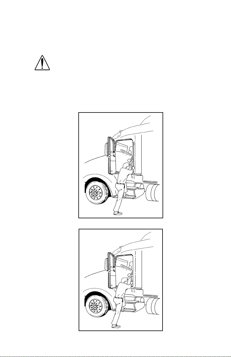
Be careful whenever you get into or out of your vehicle’s cab. Always
maintain at least three points of contact with your hands on the grab
handles and your feet on the steps.
WARNING! Jumping out of the cab or getting into the
cab without proper caution is dangerous. You could slip
and fall, possibly suffering a serious injury. Keep steps
clean. Clean any fuel, oil, or grease off of your shoes
and the steps before entering the cab. Use the steps
and grab handles provided, and always keep at least
three points of contact between your hands and feet and
the truck. Look where you are going.
The illustrations below show the best ways to enter and exit a cab.
02958-A
Vehicle With Standard External Grab Handle
02958-B
Vehicle Without Standard External Grab Handle
PB1328 —5— 22-02011 (R02/02)
Page 8

PART 2: GETTING INTO AND OUT OF THE
CAB AND FRAME ACCESS
Door Lock and Keys
Doors can be l ock ed f rom the inside by us ing the loc k button. Close the
door then push the button down to lock. Doors automatically unlock
when you open them from inside, and can be locked from the outside
with the k ey only.
WARNING! To lessen the chance and/or severity of personal injury in case of an accident, always lock the
doors while driving. Along with using the lap/shoulder
belts proper ly, locking the doors helps prevent occu pants from being thrown from the vehicle.
To lock or unlock the doors from outside the cab, insert the key in the
lock.Turn the key toward the rear to lock; forward to unlock.
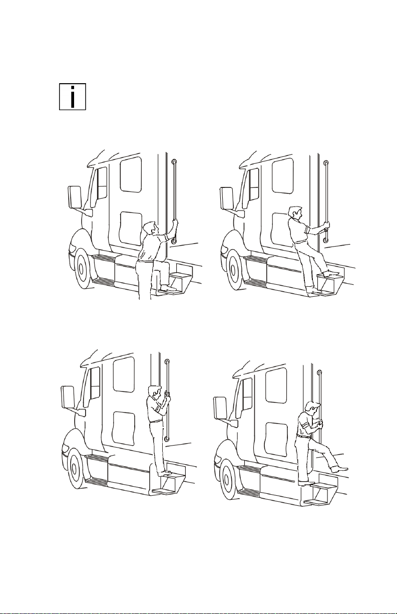
Climbing Onto the Deck Plate
When you are climbin g onto and of f the deck plate, maintain a t least
three points of contac t with your hands on the grab ha ndles and your
feet on the steps.
WARNI NG!
•
You can be hurt if you aren’t careful climbing onto
and off the deck plate. You can slip and fall, especially if the surfaces are wet or icy, or if you step in
oil, fuel, or grease. Keep steps clean. Always maintain at least three points of contact between your
hands and feet and the steps and deck plate.
•
Do not climb onto and off the deckplate–use steps
and grabhandle provided. If there is no deck plate,
or if proper steps and grab handles aren’t provided,
don’t climb on t o t he ar ea behind the cab . Peter bi lt
did not intend for the area to be a step if handrails or
proper steps are not provided.
WARNI NG! Do not step on vehicle components without
antiskid surfaces or use components not designed for
entry-and-exit use . You could fall and injure yourself if
you step on a slippery surface. For example:
•
You cou ld fall and inj u r e yourself if you step onto a
fuel tank surface. A fuel tank is not a step. The tank
surface can get very slippery, and you might not be
able to prevent a fall. Don’t step onto the surface of a
fuel tank. Use only the step s and handholds provided,
not chain hooks, quarter fenders, etc.
•
Always reinstall steps before entering the cab or
accessing the deck plate. Without steps, you could
slip and fall, resulting in possible injury to yourself.
PB1328 —6— 22-02011 (R02/02)
Page 9
PART 2: GETTING INTO AND OUT OF THE
CAB AND FRAME ACCESS
The pictures below show you the right way to get on and off the area
behind your cab.
NOTE: Any alteration (adding bulkheads, headache racks,
tool boxes, etc.) behind the cab or sleeper that affects the
utilizatio n o f grab ha nd les , de ck p lat e s, or fra m e acc es s
steps installed by Peterbilt must comply with FMCSR 399.
Hold handles as you step up Three points of contact
Three points of contact as you
reach the deck area
PB1328 —7— 22-02011 (R02/02)
Three points of contact as you
step to the deckplate
Page 10
PART 3: GETTING TO YOUR ENGINE
Hood Tilt
Follow this procedure to tilt the hood.
WARNI NG! Before opening or cl osing the hood, be sure
there are no people or objects in the way. A hood could
hurt someone in the way of its opening or descent.
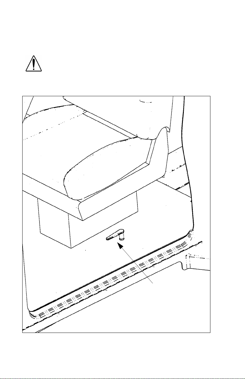
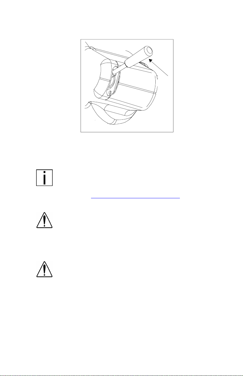
1. To open your hood, find the hood release ha ndle on the cab floor
beside the driver’s seat.
Hood
release
handle
2. Grasp the lever and turn it towards you. The hood will release and
pop open to a neutral position, approximately 2” above the closed
position.
PB1328 —8— 22-02011 (R02/02)
Page 11

PART 3: GETTING TO YOUR ENGINE
WARNING! The hood uses hydraulic dampers to contr ol
movement du rin g opening. Do no t ti lt the hoo d wi t h
these dampers disconnected. Replace damaged, worn,
or leaking dampers as soon as possible. Tilting a hood
with the dampers disconnected or defective may cause
the hood to tilt too rapidly . You could be injured and the
hood coul d be damaged .
3. Proceed to the front of the vehicle and face the hood. Grasp the
hood ornament on the top of the crown molding. Pull forward and
down until the hood is fully open and rotation stops.
WARNING! If the hood falls, anyone under it could be
injured. Always ensure that a hood is fully tilted open
any time anyone gets under a hood for any reason.
4. To close the hood, firmly push upward and rearward on the hood
ornament to star t the hood tilting backwards. Continue to push
until the hood moves through its neutral position. The hood will
continue to tilt backwards. Apply a firm push to the hood ornament to engage the hood latches located on both sides of the firewall.
PB1328 —9— 22-02011 (R02/02)
Page 12
PART 4: CONTROLS AND DISPLAYS
This par t explains t he locat ion of the various features on your vehicle
and describes their function. For information on using these features
in driving, see the paragraphs below.
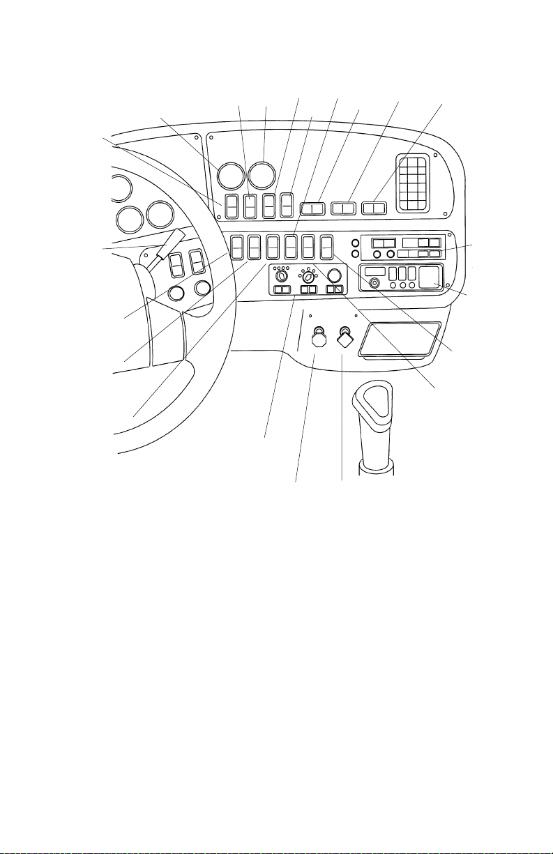
Your Instrument Panel
Please remember that each Model 387 is custom-made. Your instr ument panel may not look exactly like the one in the pictures below.
We have tried to describe the most common features and controls
available, so your vehicle may not have some of the ones that appear
in this section. You can pick out the parts that apply to you and read
them to be fully informed on how your partic ular vehicle operates.
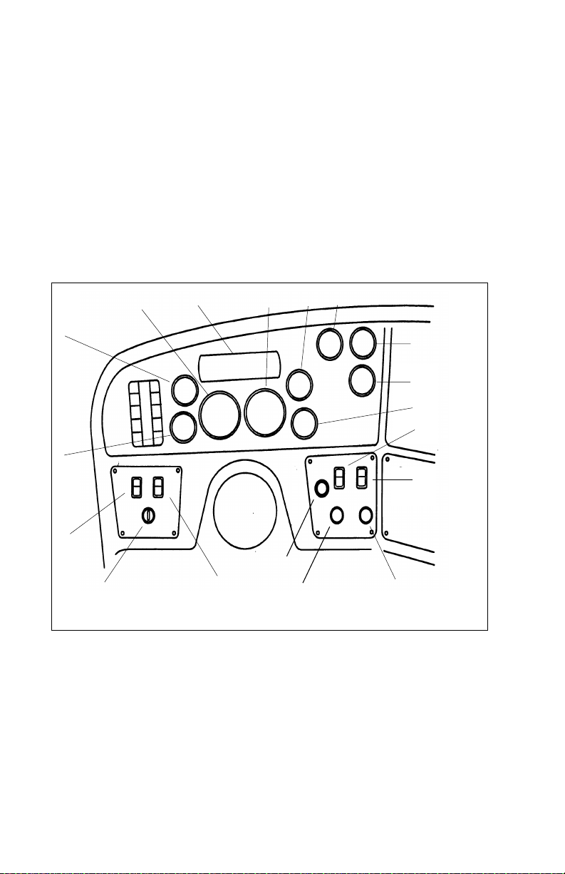
T y pical Cab Instruments and Control s
6
7
8
0
9
1
5
4
3
8
1
2
1
7
1
6
1
LEFT SIDE
1. ID/Clearan ce Lam ps Switch 10. Air Cleaner Restriction
2. Ignition Switch 11. Primary Air Pressure
3. Headlamps Switch 12. Secondary Air Pressure
4. Voltmeter 13. Fuel
5. Oil Pressure 14. SMC Select/Reset Switch
6. Tachometer 15. Dome Light Switch
7. Warning Light Bar 16. Windshield Wiper/Washer
8. Speedometer-Message Center (SMC) 17. Panel Dimmer
9. Water Temperature 18. Cigarette Lighter
1
1
2
1
3
1
4
1
5
1
B
1
7
9
2
0
PB1328 —10— 22-02011 (R02/02)
Page 13
PART 4: CONTROLS AND DISPLAYS
12
11
10
9
14
13
8
15
16
17
7
6
5
20
21
4
3
2
1
02972A
RIGHT SIDE
1. Parking Brake Valve 12. Engine Brak e
2. Trailer Air Suppl y Valve 13. Engine Brake
3. Heater/AC Control Panel 14. Load Lights Switch
4. Fog Lights Switch 15. Interaxle Differential Lock Switch
5. Engine Fan Switch 16. 5th Wheel Lock Switch
6. ID/Clearanc e Lamps Flash Switch 17. Air Suspension Switch
7. Trailer Brake Lever 18. Radio
8. Cruise Control Switch 19. CB Radio
9. Transmission Temperature 20. Selected Option Switch
10. Cruise Control Switch 21. Mirror Heater Switch
11. Pyrometer
18
19
PB1328 —11— 22-02011 (R02/02)
Page 14
PART 4: CONTROLS AND DISPLAYS
Steering Column-Mounted Controls
Turn Signal and Indicator Lights
02882C
Turn S igna l
Your turn signal lever is mounted on the left side of the steering column below the steering wheel. Green directional indicator lights
appear on the instrument panel.
NOTE: The ignition key must be turned to ON for the signal/
switch to operate.
To operate the signal, move the le ver in the direction of t he turn.
WARNING! After you complete a turn, shut the system off
by returning the le ver to the “OFF” (center) position. The
switch's lever action is NOT self-canceling. Failure to shut
off a turn signal could conf use other drivers and res ul t i n
an injury accident. An indicator light in the instrument
panel will flash until the turn signal is turned off.
PB1328 —12— 22-02011 (R02/02)
Page 15
PART 4: CONTROLS AND DISPLAYS
Hazard Flasher
02883B
Hazard Flasher
The four-way Hazard Flasher switch is on the turn signal body, just
underneath t he turn signal lever. It will operate with the key switch in
the ON or OFF pos ition. Use your hazard flasher whenever you are
off the road or on the side of the road, or in a potentially hazardous
situation. Pull it out to activate the system. All turn signals will flash at
once. To turn it o ff, m o ve th e turn si gnal leve r up or down.
WARNING! Use your Hazard Flasher Warning System any
time you have to stop off the road or on the side of the
road, day or night. A hard-to-see vehicle can result in an
injury accident. Another vehicle could run into you if you
do not set your flashers. Always move the vehicle a safe
distance off the road when stalled or stopped for repairs.
Of course, in normal stopping in traffic, such as at a stop light, you do
not use your flashers.
WARNI NG! Your disabled vehicle can be dangerous for
yo u an d ot h er s. Th e hot e xha u st sy st em co u ld ig ni te dry
grass, spilled fuel, or other substances. Do not park or
operate your vehicle where the exhaust system could
contact dry grass, brush, spilled fuel, or any other material that could cause a fire.
Air Horn
Your Model 387 has an air horn in addition to an electric horn. Control
the air horn by pul ling on the lanyard extending from the overhead
header panel.
PB1328 —13— 22-02011 (R02/02)
Page 16
PART 4: CONTROLS AND DISPLAYS
High Beam Headlights
02882C
High Beam Headlight Switch
All Peterbilt ve hicles come equipped with a combination turn sig nal and
high beam/low beam switch. To switch your headlights lower or higher,
gently pull the turn signal lever up , towards the st eering wheel , until you
hear the switch “c l i ck” and the beam changes .
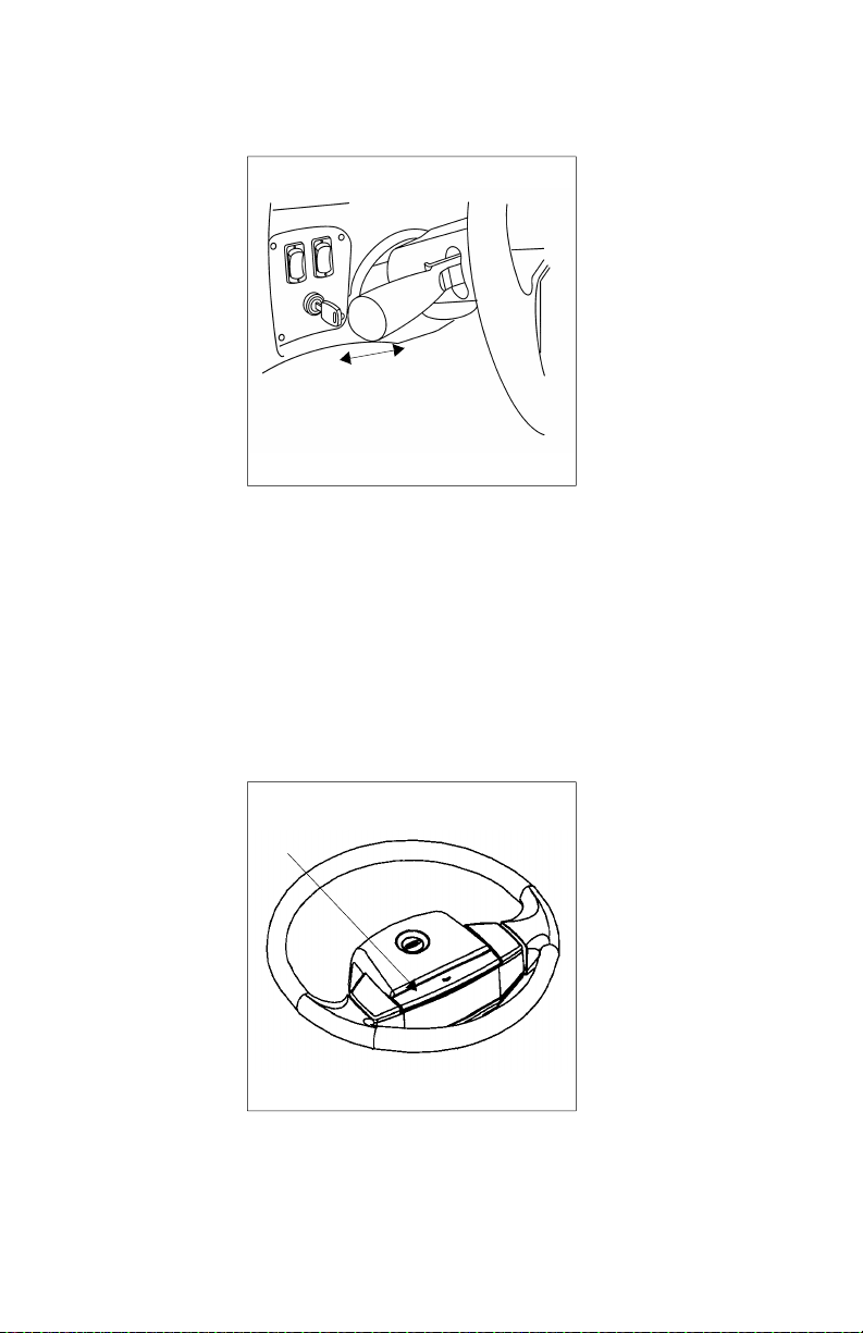
Electric Horn
Your Peterbilt has an electric hor n. To sound the horn, press on the
bar in the center of the steering wheel
27884A
PB1328 —14— 22-02011 (R02/02)
Page 17
PART 4: CONTROLS AND DISPLAYS
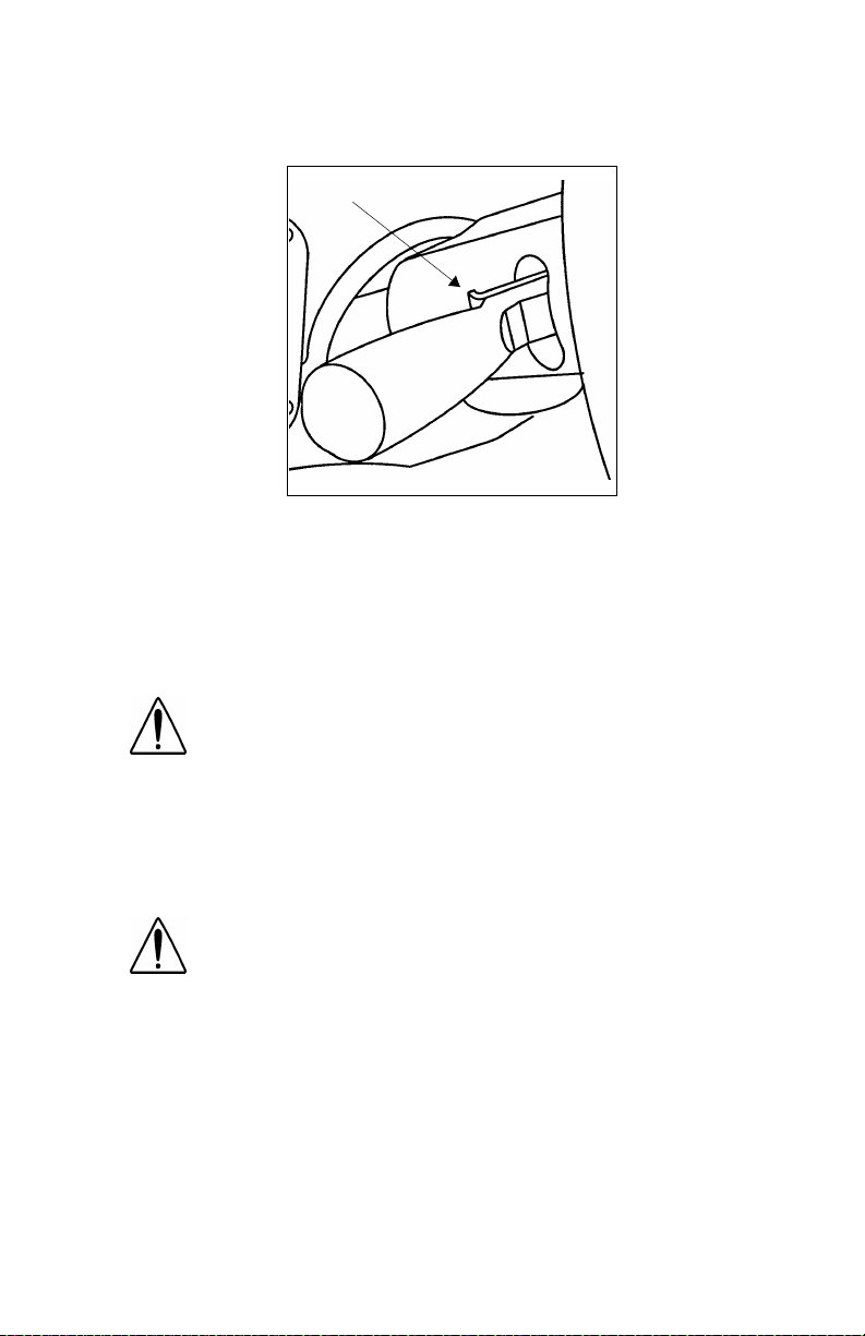
Trailer Br ake Hand Valve
02975A
This hand valve provides air pressure to apply the trailer brakes only.
It operates independently of the foot treadle valve.
To operate the trailer brake hand v al ve : pull down on t he lever under
the right side of the steering wheel.
NOTE: The trailer brake is not to be used as the main
means of braking. To use this brake frequently instead of
using the foot brake will wear out the trailer brake sooner.
See the Index, under Brake Safety and Emergency
plete information on when and how to use your trailer brake
79, for more com-
WARNI NG! It is dangerous to use air-applied trailer
brakes for parking or holding a vehicle. Air system pressure can bleed down and release the brakes. You could
have a vehicle roll-away resulting in an accident. You or
others could be badly injured. Always apply the parking
brakes for parking or holding your vehicle on grade.
WARNING! Grabbing the trailer brake hand lever
instead of the BrakeSaver lever could lead to an accident. If you have these levers, they may be close
together on your steering wheel column. Be sure you
get the one you want. The BrakeSaver lever is bent,
while the trailer parking brake lever is straight.
PB1328 —15— 22-02011 (R02/02)
Page 18
PART 4: CONTROLS AND DISPLAYS
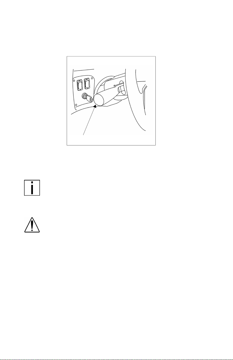
Tilt-Telescoping Steering Column
The telescoping feature of the steering wheel allows forward and rearward movement of the wheel. The tilting feature allows you to move
the wheel up and down.
Tilt-Telescope Lever
WARNING! Adjusting the Tilt-Telescoping Steering
Wheel while the vehicle is in motion could cause loss of
control. You would not be able to steer properly and
could have an accident. Make all adjustments to the
steering mechanism while the vehicle is stopped.
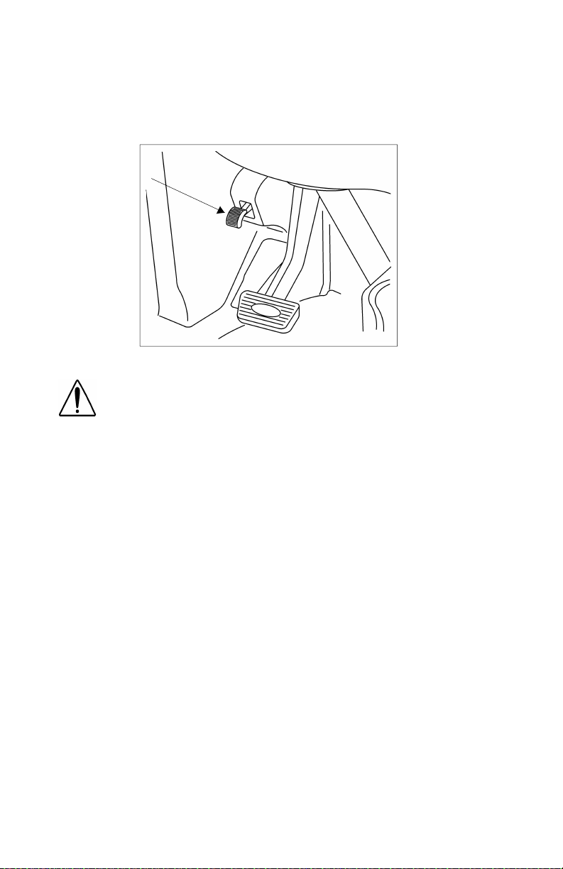
To position the wheel: Locate the Tilt-Telesc ope Lever on the floor,
to the left of the steering column. Push this lever toward the floor.
Move the steering wheel to the desired angle and height. Release the
lever to lock in the correct position.
PB1328 —16— 22-02011 (R02/02)
Page 19

PART 4: CONTROLS AND DISPLAYS
Dash-Mounted Features
Keys and Locks
The same key fits your ignition, doors, and sleeper luggage compar tment. Frame-mounted tool box locks, locking fuel tank caps, and
glove boxes each have individual keys.
Ignition Switch
Your ignition switch has four positions:
OFF
ACC ONLY
IGN & ACC
START
02977A
ACC (Accessory): With your key in this position you can play the
radio or use other accessories, but your engine
won’t start.
OFF: In this position all systems are off, and you can
remove yo ur key.
IGN & ACC: This position allows you to turn on the engine
and all accessory power.
START: Starter activation to start engine.
PB1328 —17— 22-02011 (R02/02)
Page 20
PART 4: CONTROLS AND DISPLAYS
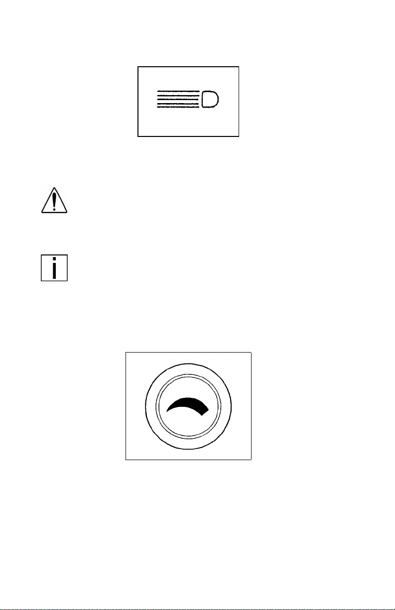
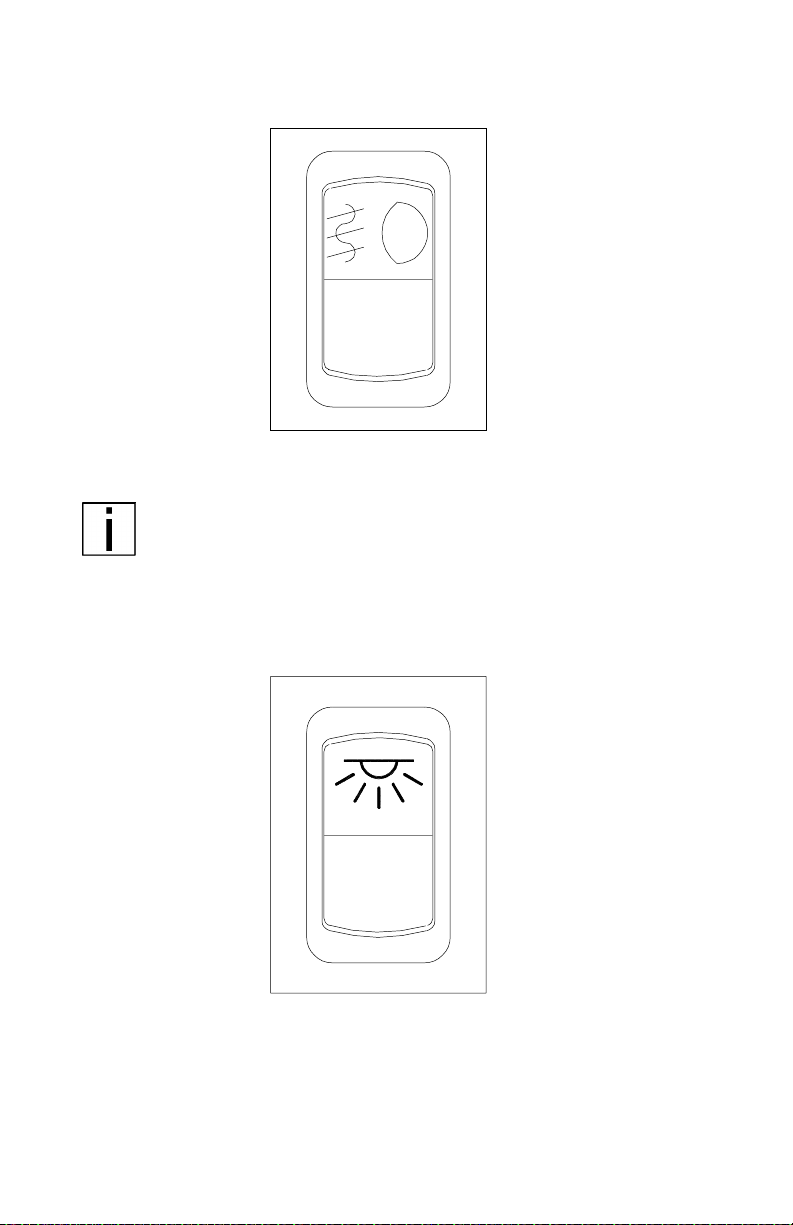
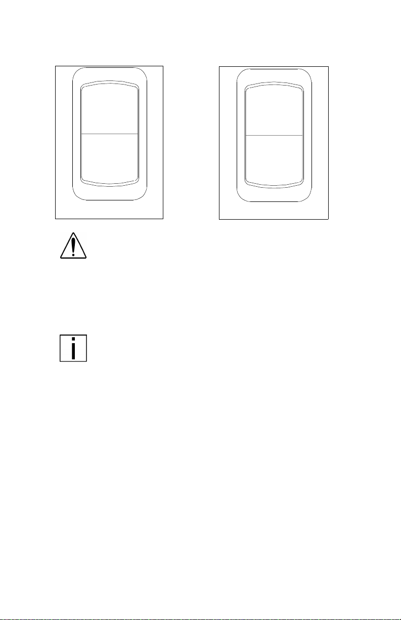
Headlights
02890
The headlights are controlled by the control panel switch showing this
symbol. When the headlights are ON, the das h lights, side, and tail
lamps are also on.
WARNING! Do not use daytime running lights (DRL)
during pe rio ds of darkness or reduced visibility. Do not
use DRL as a substitute for headlights or other lights
during operations that require lighting of your vehicle.
Doing so could lead to an injury accident.
NOTE: On vehicles equipped with daytime running lights
(DRL), the inboard park-and-turn lamps go on automatically
at reduced brightness if the engine is running and the headlamp switch is turned off. The daytime running lights are
turned off automatically while the parking brake is engaged.
If the headlamp switch is turned on, the DRL system is overridden & headlamps operate normally.
Panel Light Knob
02891
The Panel Light Knob lets you vary the bri ghtness of your instrument
panel lights.
To Operate Your Panel Light Knob:
1. Tur n on either the headlights, clearance lights, or fog/driving lights
with IGN on.
2. To brighten the instrument panel lights, turn the knob clockwise (to
the right).
3. To dim the instrument lights or to turn them off, turn the knob counterclockw ise (to th e left ) .
PB1328 —18— 22-02011 (R02/02)
Page 21
PART 4: CONTROLS AND DISPLAYS
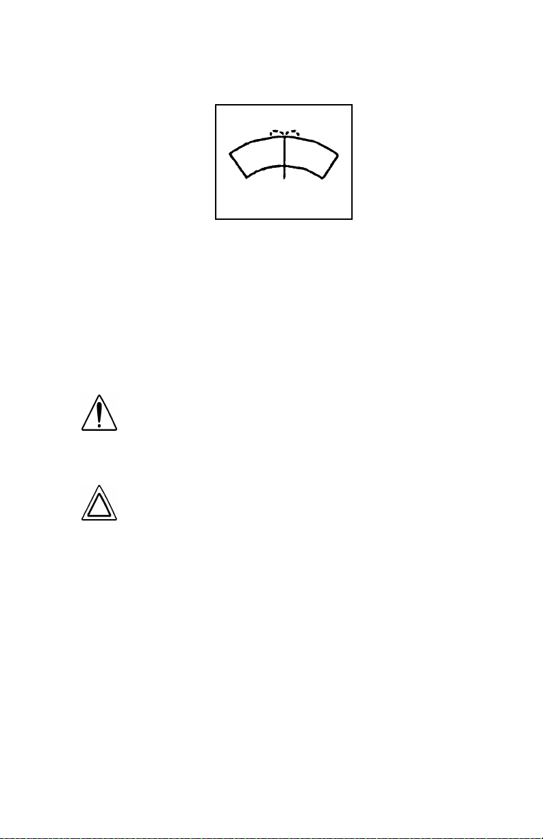
ID and Clearance Lights Switches
These are the amber lights on top of your cab, the lights on the front
and sides of the trailer and the red lights on the rear of a t ruck or trailer.
They may be turned on and off by the switch located on the lower left
control panel labeled CL LPS and showing the symbol below.
02892
When your clearance lights are turned on, you may blink or flash them
by operating the flash switch located on the right side of the dash
showing the symbol be low. Press and release this rocker switch to
flash your clearance lights.
03912-1
PB1328 —19— 22-02011 (R02/02)
Page 22
PART 4: CONTROLS AND DISPLAYS
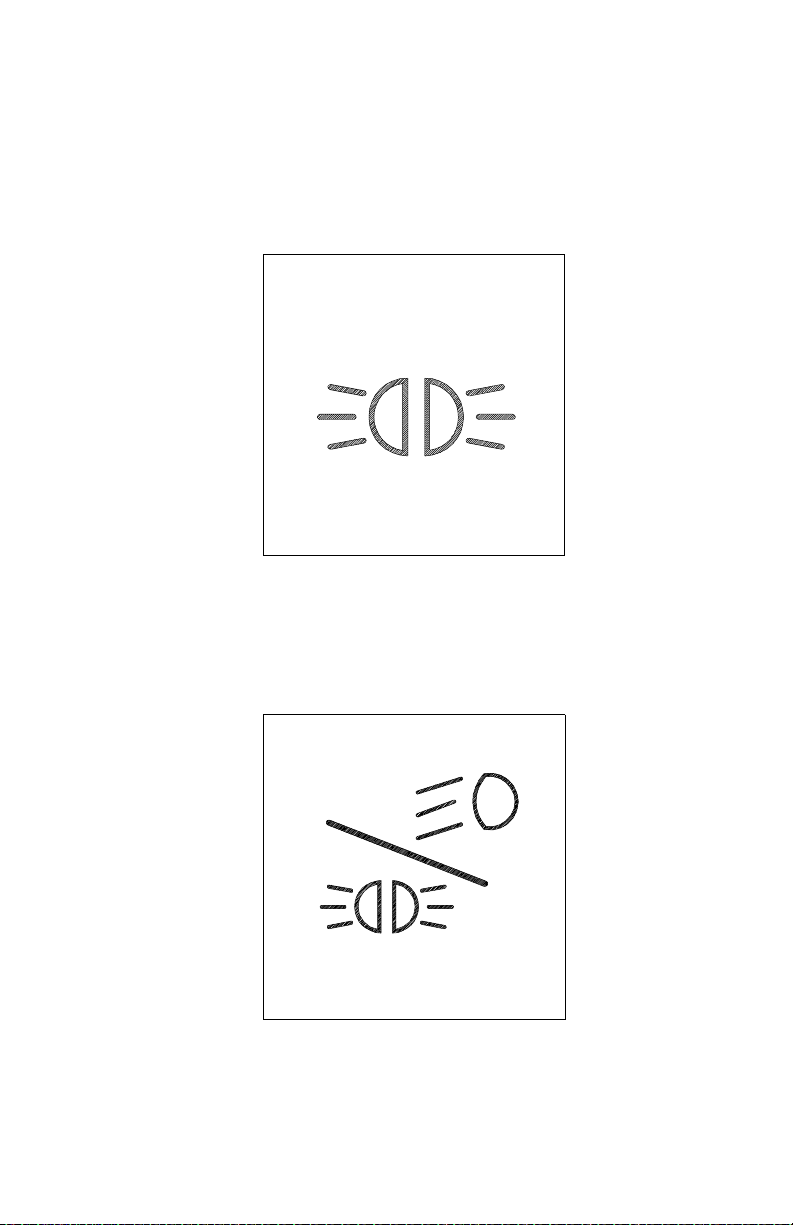
Fog/ Driving Lights Switch
I
O
03021
If your vehicle has fog/driving lights, turn them ON or OFF with the
control panel switch shown above.
NOTE: State requirements vary as to when high beams and
fog lights can and cannot be used together. Further, some
states allow only four lights to be used together; some allow
more. Whether you have dual or composite lights will affect
how many lights you can have on at one time. Always comply with the state requirements where you are driving.
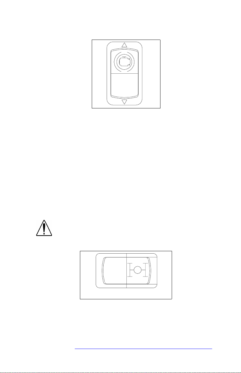
Dome Light Switch
I
O
02894A
A momentary switch controls the main dome light:
• OFF (O) Position: Light is off.
• ON (I) Position:
-Press once: Light will turn on at high intensity.
-Press again: Light will shift to low intens it y.
-Press a third time: Light will turn off.
PB1328 —20— 22-02011 (R02/02)
Page 23
PART 4: CONTROLS AND DISPLAYS
Windshield Wipers and Washer s
02896
Wiper
To turn on the wipers rotate the knob to the right. As the knob is
rotated, the speed of the wipers increases. To turn off the wipers,
rotate the knob to the left.
Washer
To use the washer, pus h the knob showing the symbol above. With
the electric wipers, the wipers will come on for a short time when the
washer starts.
WARNING! Do not drive with worn or dirty wiper blades.
They can reduce visibility, making driving hazardous.
Clean blades regularly to remove road film and wax buildup. Use an alcohol-based cleaning solution and a lint-free
cloth, and wipe along the blades.
CAUTION: Do not use antifreeze or engine coolant in the
windshield washer reservoir—damage to seals and other
components will result.
Intermittent Windshield Wiper Control
Two-speed intermittent windshield wipers are controlled by the control
panel knob with the symbol shown above. To turn on the wipers,
rotate the knob to the right.
As you turn the knob further to the right, inter m ittent delay decreases
until the knob encounters the first position for continuous operation.
Turn the knob further right to the next position fo r higher speed continuous operation. Turn off the wipers by rotating the knob to the left.
PB1328 —21— 22-02011 (R02/02)
Page 24
PART 4: CONTROLS AND DISPLAYS
Air Suspension Deflate Switch (Dump Valve)
AIR SUSPENSION
03035
Your Model 387 may have an air suspension deflation switch that
allows the air in the suspension to be exhausted fr om a switch on the
dash. The purpose of this feature i s t o allow you to lower your tractor
to get under a trailer.
You will notice a gu ard over the switch. This prevents you from accidentally deflating the suspension.
WARNI NG! Operating the Air Suspension Deflate
Switch (Dump Valve) while driving can lead to an accident. Sudden deflation while your vehicle is moving can
affect hand li ng an d control. Use this switc h on ly when
your vehicle is not moving.
CAUTION: Operating a vehicle with air suspension bags
either overinflated or underinflated may cause damage
to driveline components. If a vehicle must be operated
under such conditions, do not exceed 5 mph.
PB1328 —22— 22-02011 (R02/02)
Page 25
PART 4: CONTROLS AND DISPLAYS
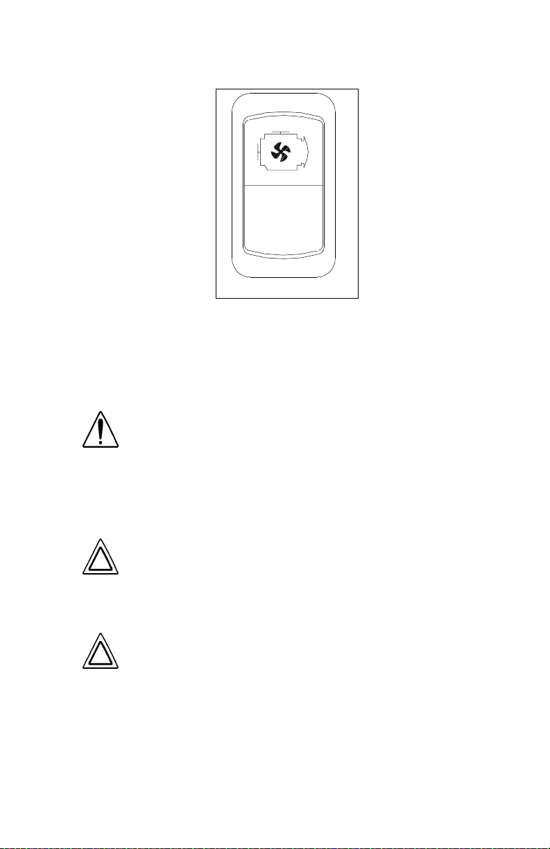
Engine Fan Switch
I
0
03023
The engine fan switch allows you to control the engine fan manually
or automatically. With the ignition key switch ON and the fan switch in
the ON position, the e ngine fan will be on regardless of engine temperature. With the engine fan switch in the AUTOMAT IC position, th e
engine fan will automatically turn on when the engine coolant reaches
a temperature of about 200
WARNING! Do not work on the fan with the engine running. Anyone near the engine fan when it turns on could
be badly injured. If it is set at ON, it will turn on any time
the ignition key switch is turned to the ON position. In
AU T O MATIC, i t coul d e ng age sud d enl y wi th ou t wa rni ng .
Before turning on t he i gni t io n or switching from AUTOMATIC to ON, be sure no one is near the fan.
°F.
CAUTION: The fan or equi pm ent near it co ul d be dam -
aged if the fan turns on suddenly when you don’t expect
it. Keep all tools and equipment such as rags away from
the fan, and take care no one turns on the ignition when
someone is working near the fan.
CAUTION: Do not op era te the engine fan in th e manual
(ON) position for e xtended perio ds of ti me. The fan hub
was designed for intermittent operation. Sustained
operation will shorten the fan hub’s service life as well
as reduce fuel economy.
PB1328 —23— 22-02011 (R02/02)
Page 26

PART 4: CONTROLS AND DISPLAYS
Mirro r Heat Switch
I
O
03022
Mirror heat is controlled by the control panel switch shown above. If
the vehicle is equipped with this switch, mirror heat can be switched
on to help remove frost and ice from the mirror glass.
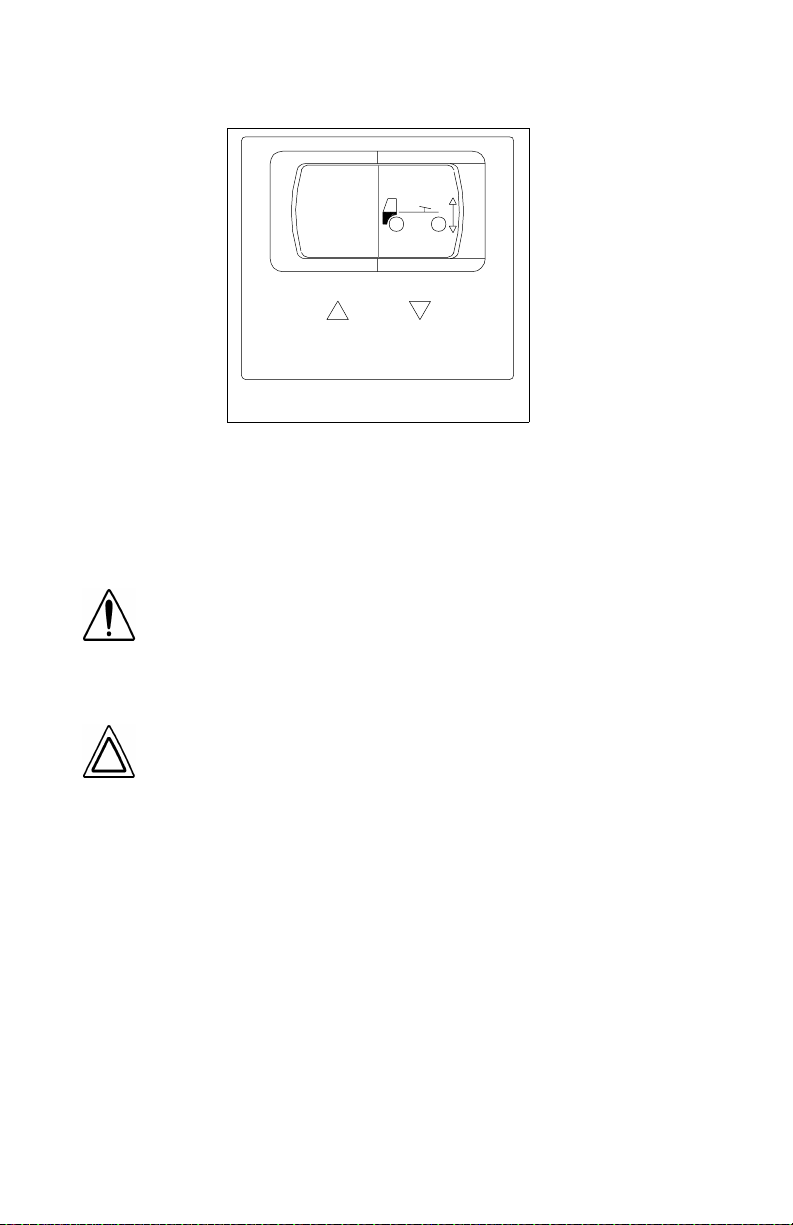
Pow er Mirr or Switch
WARNING! Convex mirrors can distort images and make
objects appear smaller and farther away than they really
are. You could have an accident if you are too close to
another vehicle or other object. Keep plenty of space
between your vehicle and others when you turn or change
lanes. Remember that other objects are closer than they
may appear.
The power mirror control cont rols the adjustment of the r ight or left
outside mirrors, depending on the option select ed. It is located in th e
driver side armrest.
NOTE: The Power Mirror Switch does not control the adjustment of the convex mirrors.
PB1328 —24— 22-02011 (R02/02)
Page 27
PART 4: CONTROLS AND DISPLAYS
CRUISE
ON/OFF
I
0
03025
Cruise Control Switch
SET
CRUISE
SELECT
RESET
03026
WARNING! Do not operate the cruise control when operating on road surfaces with poor traction (wet, icy, or snow
covered roads) or in heavy traffic. Accelerations caused by
the normal operation of the cruise control could cause you
to lose control of the vehicle resulting in an injury accident.
The master switch turns t he cruise control ON or OFF. The second
switch allows you to SET the desired speed or RESET the desired
speed after the cruise control function has been interrupted.
NOTE: Cruise control functions and features may vary
depending upon which engine you have. For specific explanation of your cruise control, see the cruise control or engine
manual included with your vehicle.
PB1328 —25— 22-02011 (R02/02)
Page 28

PART 4: CONTROLS AND DISPLAYS
Digital Message Center
ENTER
∨
∨
DIAG
TRIP
°
FUEL
∨
SENSOR
°
CLOCK
MAINT
INFO
RESET MSG
∨
CANCEL
03038
The optional digital mess age center (DMC) is an onboard computer
used to provide the following:
• trip inform a ti on
• clock/calendar
• fuel economy
• sensor data
• fault codes
• maintenance information
• warning messages
The DMC vacuum-fluorescent display is capable of displaying 40
characters. Navigation through the information is done by means of
an integral keypad. Refer to the DMC operator’s manual that came
with the vehicle for more information on using this component.
PB1328 —26— 22-02011 (R02/02)
Page 29
PART 4: CONTROLS AND DISPLAYS
Engine Brake
03028
When an eng ine brake is ene rgized, the power-produc ing dies el eng ine
is converted into a power-absorbing air compressor to retard the vehicle.
• The brake is energized whenever the driver’s foot is completely
removed from the accelerator pedal.
• The brake is deenergized during driving by pressure on the accel-
erator pedal, and during shifting by depressing the clutch pedal.
The ON/OFF toggle switch turns the system ON or OFF.
• In Caterpillar- and Cum mi ns- powered vehicles equipped w ith a
Jacobs Engine Brake, a second two- or three-mode switch is incorporated in the instrument panel. With this system, you can select
either LOW or HIGH or LOW/MEDIUM/HIGH retarding.
For more information on when and how to use the engine brake in
your vehicle, see the owner’s manual for the engine brake.
WARNING! Using the engine brake when operating on
surfaces with poor traction (such as wet or icy, slipp ery
roads or gravel) could cause loss of control.
Two-Speed Rear Axle (Range) Switch
2
03030
If your vehicle is equipped with a t wo-speed rear axle, you can select
the axle range by the dash mounted switch shown above.
• The low range provides maximum torque for operating off-highway .
• The high range is a faster ratio for highway speeds.
For information on how to operate your two-speed rear axle properly
and safely, see PART 7: STARTING & OPERATING THE VEHICLE
PB1328 —27— 22-02011 (R02/02)
.
Page 30
PART 4: CONTROLS AND DISPLAYS
Interaxl e D i ffer en tial Lock Swi tch
WARNING! Placing the differential lock in the “LOCK”
position while y our wheels ar e spinning c ould cause loss
of control or axle damage. You could be hurt. Switch to
“LOCK” only when your wheels are not spinning.
SHIFT AT ANY SPEED EXCEPT
IF A WHEEL IS SPINNING
03029
The interaxle differential allows differential action between the forward
rear and the rear rear driving axles. The interaxle differential lock
switch allows the operator to LOCK or UNLOCK the differential. The
guard over this switch preve nts you from accidentally activating the
lock. See “
using your interaxle differential.
Fifth Wheel Lock (Slider Adjustment) Switch
Inter axle Differ ential ” on page 72 for mo re information on
WARNI NG!
Do not move of the fifth wheel while the trac-
tor-trailer is in motion.
0
CAB CONTROL
1
03031
Movement of the fifth wheel while
a tractor-trailer is moving can cause a serious accident.
Yo ur load could shi f t sudd enly, causing you to lose control of the vehicle. Never operate the vehicle with the
switch in the unlock position. Always inspect the fifth
wheel after you lock the switch to be sure the fifth wheel
is engaged
Vehicles having an air slide fifth wheel have a fifth wheel slider lock
controlled by a switch on the instrument panel. By placing the switch
in the unlock position, you can slide the fifth wheel to various positions to adjust weight distribution. There i s a guard over this switch to
protect you against accidentally activating or releasing the lock.
PB1328 —28— 22-02011 (R02/02)
Page 31

PART 4: CONTROLS AND DISPLAYS
Parking Brake Valve and Trailer Air Supply Valve
Your parking brake valve is a yellow diamond-shaped knob located
below the right instrument panel. It controls the parking brakes.
02909
WARNING! Stopping with the parking brake controls
can cause a sudden wheel lock-up, loss of control, or
can cause you to be overtaken by following vehicles.
Yo u could be severely inju red. Never pull out th e park ing brake valve while the vehicle is moving.
To apply all parking brakes, pull the yellow, or parking brake, knob
out. The truck or tractor parking brakes will set, and the Trailer Air
Supply Valve (red octagon knob) will automatically trip (“pop out”) and
set the trailer parking brakes. To release bot h truck/tractor and trailer
parking brakes, push in BOTH yellow and red knobs. For full information on using parking brakes, see the Index, under Brake
Heater-Air Conditioning Controls
Your heat and air conditioning controls are m ounted in the right hand
instrument panel. Additionally, the sleeper compartment may also
contain a separate heating and cooling system with separate controls.
.
WARNING! Exhaust fumes from the engine contain carbon
monox ide, a color l es s and odo r les s gas . Do no t breat he the
engine exha ust gas . A poorly maintained , dama ged or corroded e xha ust sy ste m can al lo w car bon monoxide to enter
the cab or slee per. Entry of carbon mono xi de into the cab is
also pos sib le from other vehicles n ear b y. Fail ure to properly
maintai n yo ur vehic le cou ld caus e carbo n mono xide to ente r
the cab/sleeper and causes serious illness.
PB1328 —29— 22-02011 (R02/02)
Page 32

PART 4: CONTROLS AND DISPLAYS
CAUTION: Never idle y our vehic le for prolonged periods of
time if you sense that exhaust fumes are entering the cab
or sleeper . In vestigat e the cause of the fu mes and correct it
as soon as possible. If the vehicle must be driven under
these conditions, drive only with the windows slightly
open. Failure to repair the source of the exhaust fumes may
lead to personal harm.
NOTE: Keep the engine exhaust system and the vehicle’s cab/
sleeper ventilation system properly maintained. It is recommended
that the vehicle’s exhaust system and cab/sleeper be inspected
•
By a competent technician every 15,000 miles
•
Whenever a change is noticed in the sound of the
exhaust system
•
Whenever the exhaust system, underbody, cab or
sleeper is damaged
NOTE: To allow for proper operation of the vehicle ventilation
system, keep the inlet grille at the base of the windshield clear
of snow, ice, leaves and other obstructions at all times.
NOTE: Do not stay in the vehicle with the engine running or
idling for more than 10 minutes with the vehicle’s Heater and
A/C ventilation system in RECIRC or at LOW FAN SPEED.
Even with the ventilation system On, running the engine
while parked or stopped for prolonged periods of time is not
recommended.
NOTE: If y ou are required to i dle y our v ehi cl e f o r lo ng perio ds of
time, ins tall an auxi liary heater or automatic idle control . These auxi liary devi ces can r educ e fu el c ons umpt ion and s a v e you money.
NOTE: When idling for short periods of time
•
Set the heating or cooling system to Heat or A/C
•
Set the fan to Medium or High speed
•
Set the controls to FRESH AIR
NOTE: If other vehicles are parked next to you idling, move
your vehicl e or do not stay in your vehic le f or prolonged periods
of time.
PB1328 —30— 22-02011 (R02/02)
Page 33

PART 4: CONTROLS AND DISPLAYS
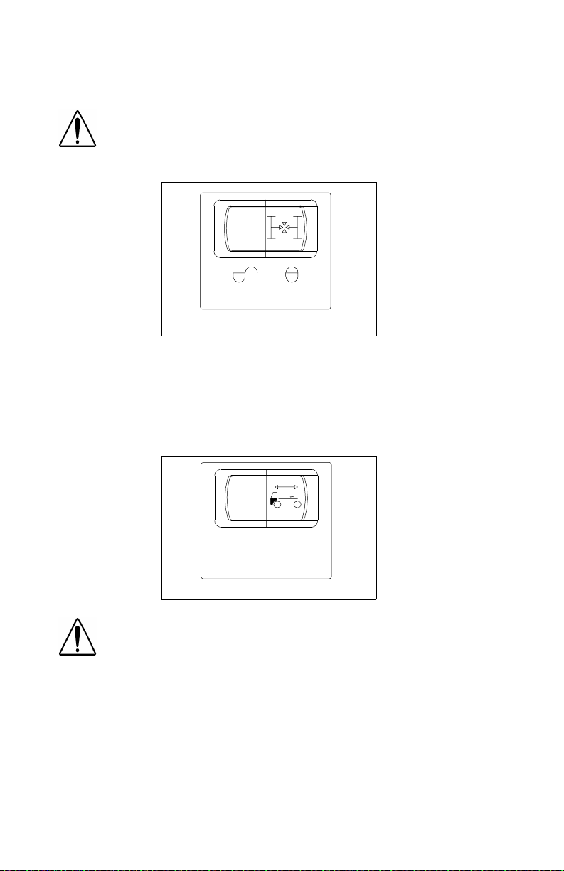
To Set the Heater-Air Conditioning Controls
The cab’s control panel may have up to six controls (see illustration
below); :
• A rotary knob (A) in the up per left portion co nt rolling the blower
speed with four settings.
• A rotary knob (B) in the up per center p ortion c on t r olling the move-
ment of air within the cab. This control is continuously variable
through five modes (clockwise from left):
- Panel
- Panel/Floor
- Floor
- Defrost/Floor
- Defrost
• A rotary knob (C) in the upper right portion controlling the air tem-
perature.
• A rocker switch (D) in the lower l eft portion to engage the air condi-
tioner compressor.
• A rocker switch (E) on the lower center portion to send power to
the “bunk” or sleeper control panel.
• A rocker switch (F) in the lower right portion to select either fresh
or recirculated air mode.
3
B
4
E
F
C
02980B
A
2
1
D
The sleeper control panel will have two controls (see illust ration on
next page):
• A rotary knob in the left portion controlling the blower speed with
four settings.
• A rotary knob in the right portion controlling the air temperature.
PB1328 —31— 22-02011 (R02/02)
Page 34

PART 4: CONTROLS AND DISPLAYS
2
1
3
4
02981B
The cab “bunk” control rocker switch must be ON for the sleeper controls to function.
• To heat the cab, select the desired air mode and set the tempera-
ture knob to hot (the red position on the control) and the blower to
whatever speed makes you most comfortable.
WARNING! Do not drive with visibility reduced by fog, condensation, or frost on the windshield. Your view may be
obscured, which could result in an injury accident. For
clear visibility and safe driving it is extremely important for
you to follow the instructions pertaining to the function and
use of the ventilation/heating and defogging/def rosting
system. If in doubt, consult your dealer. Maximum heating
output and fast defrosting can be obtained only after the
engine has reached operating temperature.
CAUTION: During extreme cold weather, do not blow hot
defroster air onto cold windshields. This could crack the
glass. Turn the air flow control lever to Defrost and adjust
the fan speed accordingly while the engine warms. If the
engine is already warm, move the temperature selector to
Cool, then gradually increase the temperature when you
see that the windshield is starting to warm up.
• To defog the windshield , s elect the Defrost mode and tur n the
blower speed to high. Set the temperature knob to hot (the red
position on the control). The air conditioner is automatically activated to remove moisture from the cab. After the windshield is
clear, adjust the mode, blower speed, and temperature to your
comfort.
• To cool the cab, turn on the A/C switch, set the temperature knob
to cool (the blue position on the control), and the blower to high
until the cab becomes cool. Then you can turn down the blower if
you wish.
PB1328 —32— 22-02011 (R02/02)
Page 35

PART 4: CONTROLS AND DISPLAYS
For Efficient Cooling:
1. Be sure all heater - air conditioner controls are off.
2. Start the engine. Allow time for warm-up.
CAUTION:
•
A cold compressor can cause refrige rant to liquefy
and warp the valve plates or cause a hydraulic lock.
Warm the engine before starting the air conditioner.
•
To avoid damage to the compressor& blower motors,
turn off all controls when a system is not in use.
3. Set the air control in the RECIRC mode.
4. Close all windows.
5. Idle the engine between 1000 and 1500 RPM and turn the blower
speed control to high.
6. After the cab temperature cools to a comfortable level, adjust the
blower speed and controls to keep the desired condition.
NOTE: When the air conditioner isn’t in regular use, operate
it for at least 15 minutes at least once a month or every
5,000 miles(8,000 Km), whichever comes first. This will l ubricate the seals in the air conditi on ing system. The air conditioning system is active when the Defrost mode is selected.
Cigarette Lighter
02912
Lighter
To operate your lighter, push the knob in. After a few moments the
lighter will automatically pop out, ready to us e. After use, insert the
knob, but don’t push it in. The lighter circuit is protected by a 10ampere polyswitch to prevent damage should the lighter get stuck in
the IN position. If this fuse needs rep lacement, check to e nsure that
the lighter is not stuck before replacing the fuse.
WARNING! Do not exceed the voltage/amperage capacity
of the cigarette lighter. It could result in a fire. Follow all
warnings and instructions in th e operator’s manual for the
appliance you are using.
PB1328 —33— 22-02011 (R02/02)
Page 36

PART 4: CONTROLS AND DISPLAYS
The lighter receptacle may be used to power auxiliary equipm ent that
does not draw more than 10 amperes maximum.
Ashtray
WARNI NG! Paper or other combustible substances in
an ashtray could cause a fire. Keep all burnable materials besides smoking materials out of the ashtray.
Glove Com pa rtment
To open your glove compartment, pull the latch. To close it, push the
cover up and press to latch it.
The glove compartment can be locked. Turn your glove box ke y cloc kwise (right) to lock and counterclockwise (left) to unlock.
WARNING! An open glove compartment can be dangerous. In an accident or sudden stop, you or a passenger
could be thrown against the cover and injured. Keep the
cover closed when the vehicle is in motion.
PB1328 —34— 22-02011 (R02/02)
Page 37

PART 4: CONTROLS AND DISPLAYS
Gauges
On the pages that follow you will find descriptions of some of the
gauges on your instrument panel. For more information about using
them in driving, see PART 7: STARTING & OPERATING THE VEHI-
CLE. Also check the Index under the name of the gauge or function
you want to know more about.
WARNING! Do not ignore a warning light or buzzer. These
signals tell you something is wrong with your vehicle. It
could be a failure in an important system, such as the
brakes, which could lead to an accident. Have the appropriate system checked immediately.
NOTE: All of the warning lights and alarms for functions
monitored by the multiplex instrumentation system instrument system are contained within the individual gauges of
the system. The alarms for other controls or systems that
you may have will be displayed separately on the instrument
panel. They are described further in PART 7: STARTING &
OPERATING THE VEHICLEof this manual.
Speedometer-Message Center (SMC)
11243
The speedometer-message center (SMC) is a combination of a
speedometer and a m ess age ce nter. The speedometer indicates your
vehicle’s speed in both miles and kilometers per hour. The message
center contains a 7-character, segmented LCD screen that can display the following items:
• Odometer •Hourmeter
• Trip 1 odometer •Clock
• Trip 2 odometer •Clock alarm
• Warning and Diagnostic messages (see page 96)
A Select/Reset sw i t ch on the right si de of the dash co ntrols the di splay.
PB1328 —35— 22-02011 (R02/02)
Page 38

PART 4: CONTROLS AND DISPLAYS
The odometer is normally displayed on the screen. To choose another
function, press and release the Select switch until it appears.
• The odometer reads miles & tenths; e.g., 123456.7
• The Trip 1 odometer reads miles & tenths; e.g., 1234.5T1
• The Trip 2 odometer reads miles & tenths; e.g., 1234.5T2
• The hourmeter reads in hours; e.g., 12345HR
• The clock reads in hours & minutes, with A.M. or P.M.indicated at
the end; e.g., _ _ 12:34A (or P).
• If the clock alarm is set and activated, the display will appear as
* _ 12:34A (or P).
• The clock alarm reads in hours & minutes, with A.M. or P.M. indi-
cated as shown; e.g., AL12:34A (or P).
To set or reset a function, follow the procedures below.
NOTE: Neither the odometer nor the hourmeter can be
reset.
1. Turn the ignition switch to ON.
2. Choose the desired function.
3. Set or reset the function:
• Trip Odometers: Press and hold the Reset switch until t he mileage
is reset to zero; this will take about 3 seconds.
• Clock
a. Press & release the Reset switch; the hours digit will flash.
b. Press & hold the Select switch; the hours digits will increase
until the switch is released. Scroll through 12 hours to change
between A.M. and P.M.
c. Press & release the Reset switch; the hours digits will stop
flashing, and the minutes digits will begin to flash.
d. Press & hold the Select switch; the minutes digits will increase
until the switch is released.
e. Press & release the Reset switch; the minutes digits will stop
flashing. The clock is now set.
• Clock Alarm
a. Press & release the Reset switch; the hours digit will flash.
b. Press & hold the Select switch; the hours digits will increase
until the switch is released. Scroll through 12 hours to change
between A.M. and P.M.
c. Press & release the Reset switch; the hours digits will stop
flashing, and the minutes digits will begin to flash.
d. Press & hold the Select switch; the minutes digits will increase
until the switch is released.
PB1328 —36— 22-02011 (R02/02)
Page 39

PART 4: CONTROLS AND DISPLAYS
e. Press & release the Reset switch; the minutes digits will stop
flashing. The alarm is now set and activated (the “*” symbol will
show in the clock display to indicate this).
-To turn the alarm OFF or ON, press & hold the Select switch for
3 seconds while viewing any display.
-To deactivate the buzzer when the alarm sounds, press &
release the Select switch. (Not e : The a larm will au t o m a ti c ally
deactivate after 60 seconds.)
NOTE: When the ignition is OFF, the SMC will be in a
“sleep” (blank) mode. To “awaken” it, press the
switch. The SMC will function normally while awake; it will
return to a “sleep” mode 20 seconds after a switch is last
pressed.
Further use and operation of the SMC is covered in PART 7: START-
ING & OPERATING THE VEHICLE of this manual.
Tachome ter
“Select”
11244B
Your tachometer measures the engine speed in revolutions-perminute (RPM). Watching your tachometer is important to driving e fficiently. It will let you match driving speed and gear selection to the
operating range of your engine. If your engine speed gets too high,
you can select a higher gear t o lower the RPM. If your engine spe ed
drops too low, you can select a lower gear to raise the RPM.
PB1328 —37— 22-02011 (R02/02)
Page 40

PART 4: CONTROLS AND DISPLAYS
Air Application Gauge
11458
This gauge will show you how much air pressure is being applied
from your foot brake valve or trailer brake hand valve.
Primary And Secondary Air Pressure Gauges (Air Reservoir)
WARNING! The air pressure warning light and the audible
alarm indicate a dangerous situation. There is not enough
air pressure in the reservoirs for repeated braking and the
brake system has failed. If air pressure falls below
(414 kPa) the spring brakes could suddenly apply, causing
a wheel lockup, loss of control, or your vehicle to be overtaken by following vehicles. You could be in an accident
and severely injured. If these alarms come on while you are
driving, bring your vehicle to a safe stop right away. If the
light and alarm do not turn off at start-up, do not tr y to
drive the vehicle until the problem is found and fixed.
60 psi
These air pressure gauges indicate the amount of air pressure in the
brake system in pounds per square inch (psi). The primary gauge
shows the front reservoir air pressure.
11465
PB1328 —38— 22-02011 (R02/02)
Page 41

PART 4: CONTROLS AND DISPLAYS
The secondary gauge indicates pressure in the rear reservoir.
11464
Engine Oil Pressure Gauge
11241A
It is impor tant to maintain oil pressure within acceptable limits. Your
engine manual will gi ve you normal operati ng pressures for your particular engine.
CAUTION: Continuing to operate y our vehicle with in-sufficient oil pressure will cause serious engine damage.
• If your oil pressure fails to rise within 10 seconds after your engine
starts, stop the engine and determine the cause.
• If your oil pressure suddenly drops while you are driving, bring the
vehicle to a stop as soon as possible in a safe location off the road
and turn off the engine. Wait a few minutes to allow oil to drain into
the oil pan, and then check the oil level. Add oil if necessary. If the
problem persists, contact an authorized service center.
PB1328 —39— 22-02011 (R02/02)
Page 42
PART 4: CONTROLS AND DISPLAYS
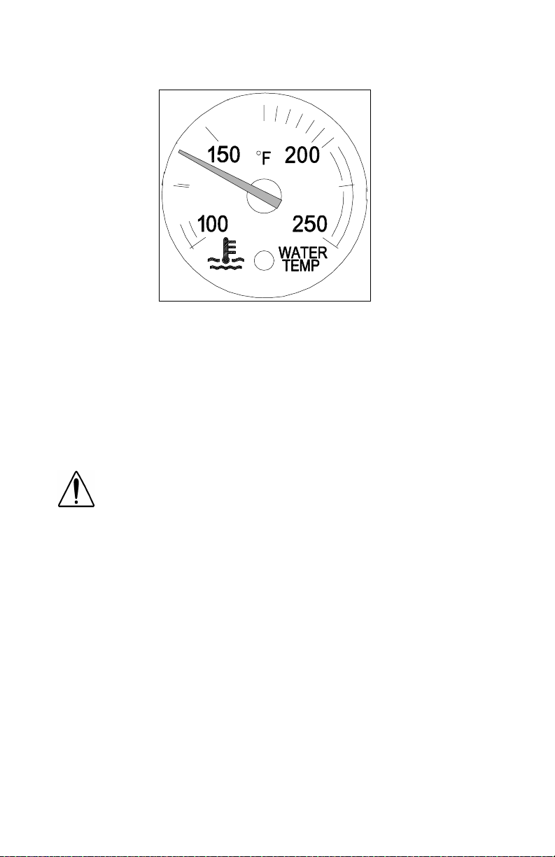
Water Temperature Gauge
11242A
The water temperature gauge shows the temperature of the engine
coolant. Under normal operating conditions the water temperature
gauge should register between 165° and 210° - 225° F (99° and
107° C), depending on the e ngine. Under certain conditions, somewhat higher temperatures may be acceptable. But the maximum
allowable temperature is 225° F (107° C) with the cooling system
pressurized, except for certain special engines. Check your engine
manual to be sure.
Engine Overheating
WARNING! Do not rem ove the radiat or fill cap while t he
engine is hot. Scalding steam and fluid under pressure may
escape an d cause ser io us perso nal inju ri es. You could be
badly burned.
•
Wait until the coolant temperature is below 122°F
(50°C).
•
Protect face, hands, and arms by covering the cap with
a large, thick rag to protect against escaping fluid and
steam.
•
Carefully and slowly turn the cap one-quarter of a turn
or until it reaches the first stop—allowing excess pressure to escape—push down and turn for final removal.
Wait until the coolant temperature is below 122° F (50° C). Protect
your face, hands, and arms by covering the cap with a large, thick rag
to protect you against escaping fluid and steam. Before you completely remove the cap, carefully and slowly turn the cap part way to
allow excess pressure to escape. Then push down and turn for final
removal.
The cooling system m ay overheat if the cool ant level is below n or ma l
or if there is a sudden l os s of coolant (s uch as a worn hose spli tting).
It may also temporarily overheat during s evere operating conditions
PB1328 —40— 22-02011 (R02/02)
Page 43

PART 4: CONTROLS AND DISPLAYS
such as climbing a long hill on a hot day or stoppin g af ter high-spe ed
driving.
If the “Engine Coolant Temperature” warning light comes on, or you
have any other reason to suspect the engine may be overheating:
• Stop the vehicle, bu t DON’T TURN OFF THE ENGINE unless a
low water warning device indicates a loss of coolant.
• With the transmission in neutral, check to be certain the oil pres-
sure gauge reads normal. Increase the engine spe ed to about
1100 - 1200 RPM, maximum. Return the idle speed to normal
after 2 or 3 minutes. If the warning light doesn’t go off or the temperature gauge doesn’t begin to drop, then turn the engine off.
• If the overheating came from severe operating conditions, the tem-
perature should have cooled by this time. If it has not, stop the
engine and let it cool before checking to see if the coolant is low.
Fuel Gauge
11435
WARNING! Do not remove a fuel tank cap near an open
flame. Hot fuel vapors are combustible and can cause an
explosion or fire resulting in injury or death.
The fuel gauge shows the approximate amount of fuel in the fuel
tanks. You will want to keep your fuel tanks at least half full to reduce
condensation of moisture in the tanks. This moisture can damage
your engine.
WARNING! Carrying additional fuel containers in your
vehicle is dangerous. Full or empty, they may leak,
explode, and cause or feed a fire. Don’t carry extra fuel
containers - even empty ones.
PB1328 —41— 22-02011 (R02/02)
Page 44

PART 4: CONTROLS AND DISPLAYS
Warning Lights and Buzzers
WARNING! Ignoring a warning light or buzzer could
lead to an accident. These signals tell you something is
wrong with your vehicle. It could be a failure in an
important system, such as your brakes. Never ignore a
warning signal. Have the appropriate system checked
rig h t away.
09091A
When you turn on your ign ition, the following will turn on for 3 - 5 seconds, as a test to let you know they are working.
LAMPS:
•Left Turn •Fifth W h eel
•Check Engine •Seat Belts
•Stop Engine •Right Tur n
•Diff L o ck •High Be am
•ABS •Trailer AB S
•Engine Warning
OPTIONAL LAMPS : Additiona l lamps may be operational de pending
on how the truck is equipped. These will also turn on for three seconds as a test to let you know they are working. (See ABS lamp information on page 77
.)
After this self-test period, the module operates normally.
The warning lights may indicate s omething is wrong with one of th e
vital systems on your vehicle. Check the lights frequently, and
respond properly as soon as you see one go on. These lights could
save you from a serious accident.
PB1328 —42— 22-02011 (R02/02)
Page 45

PART 4: CONTROLS AND DISPLAYS
Transmission Temperatu r e Gauge
11427
Your Transm ission Temperature Gauge indicates the t emperature of
the oil in your transmission. Watch this gauge to know when your
transmission is overheating. If it is, have it checked by an authorized
service representative. Maximum transmission temperature may vary,
depending upon the transmission and type of lubricant. It is typically
250° F (121° C); check your transmission’s owner’s manual.
Front Drive Axle or Rear Drive Axle Temperature Gauge
11425
CAUTION: Driving with very hot temperatures in your
rear drive axles can cause serious damag e to axle bearings and seals. Check axle lubrication if a driver temperature alarm sounds.
These gaug es indica te the t emperature of the lu brican t in your vehicle’s
axle(s). These temperatures will vary with the kind of load you are carrying and the driving conditions you encounter. Maximum axle temperature
may vary, depending up on t he a x le an d t ype of lub ri c an t. Very high tem peratures signal a need to have your axle(s)’ lubrication checked.
PB1328 —43— 22-02011 (R02/02)
Page 46

PART 4: CONTROLS AND DISPLAYS
Manifold Pressure Gauge
11453-1
Your manifold pressure gauge indicates the power your engine is putting out by showing the amount of turbo boos t. If the pressure indicated by your manifold pressure gauge goes down, there may be
something wrong with your engine. Have it checked by a qualified service person.
Pyrometer
11467
The pyrometer gauge indicates engine exhaust gas temperature.
Since it responds almost immediately to changes in exhaust gas temperature, the pyrometer is an excellent indicator of engine output.
Monitor it in conjunction with the tachometer and man ifold pressure
gauge. The pyrometer can be a useful aid to operating your vehicle
more efficiently and avoiding sudden changes in engine operating
temperature. See your engine owner’s manual for maximum temperature recommendations.
PB1328 —44— 22-02011 (R02/02)
Page 47

PART 4: CONTROLS AND DISPLAYS
Voltme ter
11497
Your voltmeter displays the battery voltage. Normally, it should show
12V to 14V (volts).
NOTE : Even with a healthy c harge/start system , the volt me ter ma y fall well belo w 12V during engi ne c ranking. If volt age
drops bel ow 12V and sta ys there, have the electrical s ys t em
checked.
Air Filter Restriction Indicator Gauge
11495
This gauge indicates the condition of the engine air cleaner and is
measured by inches of water (H
O (may vary with system design); a filter whose life is over will reg-
H
2
ister approximately 20” H
O (for Cummins engines) or 25” H2O (for
2
O). A clean filter should register 7”
2
Caterpillar engines).
PB1328 —45— 22-02011 (R02/02)
Page 48

PART 4: CONTROLS AND DISPLAYS
CAUTION: Continued operation wi t h t he A ir Filt er
Restriction Gauge reading 20” - 25” H
damage to the engine. Inspect the filter and replace if
necessary. Holes in the element render an air cleaner
useless and may cause the Air Filter Restriction Gauge
to give a false reading, even if the element is clogged.
Replace the element if it is damaged.
Shift Pattern Disp l ay
The correct shift pattern for your vehicle appears on your control
panel, windshield, or on a medallion in the shift knob. It is important
that you know more about your transmission t han just the shift pattern . Please read the manufacturer’s manual that is included with
your vehicle.
Mirrors
Your vehicle is equippe d with out side m irrors to en able you to see to
the sides of and behind your vehicle. Be sure they are adjus ted properly before you drive off. You will hav e the best field of view to the si de
if you adjust each mirror so you can just see the side of your vehicle in
the inboard part of the mirror.
WARNI NG! Optional convex outside rear view mirrors
make objects appear smaller and farther away than they
really are. You could have an accident if you were too
close to another vehicle or othe r obj e ct . Kee p pl ent y of
space between your vehicle and others when you turn
or change lanes. Remember that other objects are
closer than they seem.
O may cause
2
Alpine Navigation System
Your vehicle may be equipped with an Alpine Navigation System. The
Alpine Navigation System is a Global Positioning Satellite (GPS)linked computer. It receives input from multiple sources to pinpoint
your precise location. Read and understand the Alpine Navigation
System Owner’s Manual and observe the Warnings, Cautions and
Notes that f oll o w b efore using the system.
WARNING! Do not follow route suggestions, if you are
unfamiliar with the legal weight and height restrictions
of the route. Be familiar with the route the system is recommending prior to proceeding. Failure to do so could
lead to serious injury or equipment damage.
PB1328 —46— 22-02011 (R02/02)
Page 49

PART 4: CONTROLS AND DISPLAYS
WARNING! Do not look at the monitor for prolonged
periods while the vehicle is moving. Only glance at the
monitor briefly while driving. Failure to do so can result
in the driver not being attentive to the vehicle’s road
position, which could lead to an accident and possible
personal injury or equipm ent damage .
WARNING! Do not program the Navigation System
while driving. Always stop your vehicle when programming or changing the settings on the Navigation System. Programm i ng t he system whi le dr ivi ng can cause
you to take your eyes off the road, which could result in
an accident. Failure to do so could lead to serious injury
or equipment damage .
CAUTION: Do not use the Navigation System to route
you to emergency services. Not all emergency services
are in the database. Use your judgment and ask for
directions in these situations. Do not rely on the Navigation System to route you to the closest emergency services.
NOTE: Regardless of how and where the navigation system
directs you, it is your responsibility to operate the vehicle in a
safe and legal manner.
NOTE: Ensure the vol ume level of all audio de vices is set to
a level that still allows you to hear outside traffic and emergency vehicle s.
NOTE: F or commercial use, it is strongly recommended that
you always set the Route Calculation method to “MAX FWY”
(Maximum Freeways), unless your vehicle is restricted from
traveling on freeways. Refer to the Alpine Owner’s Manual
for how to set this function. This setting calculates the most
efficient use of freewa ys in determining the route to your
destination.
NOTE: The map database is the most current available at
the time of production. The database is designed to provide
you with route suggestions and does not take into account
the relative safety of a suggested route or of factors that may
affect the time required to reach your destination. See the
Alpine Owner’s Manual for more information.
PB1328 —47— 22-02011 (R02/02)
Page 50

PART 4: CONTROLS AND DISPLAYS
NOTE: There may be situations where the Navigation Sys-
tem displays the vehicle’s position erroneously . Use your
own driving judgment in these situations. See the Alpine
Owner’s Manual for more information.
Disclaimer: Peterbilt Motors Company is not responsible for erroneous data, misrouting, or any downtime or other damages as sociated
with or arising out of the use of the Navigation System.
Luggage Compartment(s)
An interior luggage compartment is under the bunk in the sleeper.
The exterior compartment is beneath the bunk, opening from the
driver’s side, on the outside of the cab.
WARNI NG! Carrying objects loose in your cab or
sleeper can be dangerous. In a sudden stop, or even
going over a bad bump, they could fly forward and strike
you or a passenger, possibly causing serious injury.
Secure loose objects. Carry any heavy objects in the
exterior luggage compartment and close it securely.
Appliances in the Cab
You may decide to equip your vehicle with a radio, a refrigerator, or
other appliances and conveniences. Be sure they are compatible with
your truck’ s electrical system. Secure them in the cab so they can’t fly
loose in a sudden stop.
WARNI NG! In a sudden stop or collision a heavy object
in your cab could strike you or anyone with you. You
could be injured or killed. Secure any appliance (such
as a refrigerator or radio) you add to your cab.
Refrigerator
Follow the procedure below to operate the refrigerator.
CAUTION: Leaving your refrigerator on when the vehi-
cle’s engine is not running will rapidly run down your
vehicle’s batteries. This may cause premature battery
failure.
NOTE:
•
For additional information abou t the refrigerator, refer to
the refrigerator owner’s manual that came with this appliance.
•
Refrigerator cooling ability decreases as sleeper temperature increases.
PB1328 —48— 22-02011 (R02/02)
Page 51

PART 4: CONTROLS AND DISPLAYS
The main power sup ply to the refrigerator and cooling fan (located
behind the refrigerator) is controlled by a switch labeled "REFRIG/
FAN" located on the sleeper control panel.
• To turn the refrigerator and cooling fan on, move the REFRIG/FAN
switch to ON, then turn the thermostat dial (located inside the
refrigerator) clockwise from the OFF setting.
• To turn the refrigerator and cooling fan off, turn the thermostat dial
inside the refrigerator counterclockwise to the OFF setting, then
move the REFRIG/FAN switch to OFF.
• To turn only the refrigerator off, turn the thermostat dial counter-
clockwise to OFF.
PB1328 —49— 22-02011 (R02/02)
Page 52

PART 5: SEAT AND RESTRAINT SYSTEMS
Seat
For information on the features and adjustment of the seat, see the
seat manufacturer’s literature included with the vehicle.
WARNI NG! Do not drive or ride with your seat back in
the reclined position. You could be injured by sliding
under the seat belts in a collision.
WARNING! Do not adjust the driver’s seat while the
vehicle is moving. The seat could move suddenly and
unexpectedly and can cause you to lose control of the
vehicle. Make all adjustments to the seat while the vehicle is stopped. After adjusting the seat and before driving off, ensure that the seat is firmly latched in position.
Seat Belts And Their Proper Use
Seat (or safety) belts have proven to be the single most effective
means available for reduc ing the risk of serious injury and deat h in
motor vehicle accidents. It’s not jus t an opinion -- it’s a fact: Seat
belts save lives.
WARNING! Do not drive vehicle without your seat belt
and your riders’ belt fastened. Riding without a safety
belt properly fastened can lead to increased injury or
death in an emergency. Unbelted riders could be thrown
into the windshield or other parts of the cab or could be
thrown out of the cab. They could strike another person.
Injuries can be much worse when riders are unbelted.
Always fasten your seat belt
02998
Person In Crash, Unbelted
PB1328 —50— 22-02011 (R02/02)
Page 53

PART 5: SEAT AND RESTRAINT SYSTEMS
Shoulder Belt
Your combination shoulder-lap belt needs proper adjustment:
• The lap portion should be worn as low on the hips as possible.
02928
Properly worn belt Improperly worn belt
WARNING! You can be seriously injured if your belt is
buckled too high. In a crash, it would apply force to
your abdomen, not your pelvic bones. This could cause
serious internal injuries. Always wear your seat belt low
over your pelvic bones.
• The shoulder portion should fit snugly across your body. It should
always be worn over the shoulder next to the door. It you put the
belt under your arm, it can’t protect you properly.
02929
Correct (over arm) Incorrect (under arm)
PB1328 —51— 22-02011 (R02/02)
Page 54

PART 5: SEAT AND RESTRAINT SYSTEMS
WARNI NG! Wearing the shoulder belt under your arm
could lead to serious injury. In a crash your body would
move too far forward, increasing the chance of head and
neck injury. And the belt would apply too much force to
the ribs, which aren’t as strong as your shoulder bones.
You could also suffer internal injuries. Wear the shoulder belt over your shoulder.
• Be sure, also, that your belt is not too loose. A loose belt could
allow you to slide under it in an accident, and that could bring the
belt up around your abdomen.
WARNING! A too-loose seat belt can lead to injury in a
crash. It can allow you to fall too far forward, possibly
causing head and neck injuries. You could strike the
wheel or the windshield. Adjust your belt so that there
is no more than one inch (25 mm) of slack.
• Watch t hat you don’t twist the belt in the process of putting it on. A
twisted belt won’t work as well to protect you.
02930
Twisted Belt
WARNING! You could be seriously injured by a twisted
belt. In a crash, the full width of the belt wouldn’t be
pro t ectin g you. And the twist ed belt could cut in t o your
body . Straighten the belt before buckling it. If you can’t,
have your dealer or service person fix it.
To connect your shoulder-lap belt: Grasp the belt tongue and pul l
in a smooth, slow motion across your chest and lap. Insert the
tongue into the buckle on the inboard side of the seat. Push down
until you hear a click. Pull on the belt to make sure it is buckled.
Check that it is positioned correctly on your body.
PB1328 —52— 22-02011 (R02/02)
Page 55

PART 5: SEAT AND RESTRAINT SYSTEMS
Comfort Feature
Your Peterbilt contains a feature des igned to eliminate cinching an d
provide improved safety and comfort. Cinching is the condition where
a belt becomes continually tighter around you during a rough, bouncy
ride. The need for this featu re increases with rou gh road conditions,
particularly over long distances.
To eliminate cinching simply activate the comfort feature at the appropriate ti me:
1. Fasten your seat belt according to the directions given earlier.
2. Lean forward to pull a little slack (about 1 inch) in the belt. Be sure
to allow only a small amount of slack. See the Warning on a loose
belt, on the previous page.
3. When the slack is right, slide the comfort feature up the belt until it
engages the D-loop.
4. To release the comfort feature, reach up and pull it down along the
belt until it no longer engages the D-loop.
5. When you want to get out of the cab, release the comfort feature,
then just push the button on the buckle.
Pregnant Women: Sometimes pregnant women worry that in a crash
the seat belt could hurt the baby. But if a woman wears her belt prop-
erly - low over her pelvis, below he r abdomen - the belt w on’t harm
the baby, even in a crash. And remember - t he best way to keep an
unborn baby safe is to keep the mother safe.
Pregnant Woman With Belt Properly Worn
Sleeper Bunk Restraints
If your cab is equipped with a sleeper, be sure to use the restraint
device. You may have belts which e ither are ov er the bu nk or cover
PB1328 —53— 22-02011 (R02/02)
Page 56

PART 5: SEAT AND RESTRAINT SYSTEMS
the opening. Of course, you do not need to use a restraint if you
sleep in a parked vehicle. But anyone using the sleeper while the
truck is in motion should be restrained in a safety device.
CAUTION: To avoid damage when lifting a bunk, remove
all items from the top of the bunk mattress, and arrange
bedding so that items will not slide down the mattress
and fall behind the bunk .
The bunk restraint is attached to the sleeper in six locations (see illustration below):
1. Two buckles at the upper rear wall
2. Two buckles at the side walls
3. Bolts in two places at the lower rear wall
There is also a buckle at the driver ’s side front of the bunk ( ) for
easy entry/exit of the sleeper with the bunk restraint in use.
1
4
2
2
3
4
• The upper rear wall: Access to the bunk is easiest when these
connections are buckled and the front buckle is detached.
• The side walls: The tenting straps are attached to the side wall
sills with easy-to-use buckles.
• The lower rear wall: The restraint is attached to the lower rear wall
by bolts that do not require removal for use or stowage of the bunk
restraint.
PB1328 —54— 22-02011 (R02/02)
Page 57

PART 5: SEAT AND RESTRAINT SYSTEMS
You will notice that if your Peterbilt has an upper bunk, it has no
restraint device. This is becaus e no one should ev er be in an up per
bunk when the vehicle is moving.
WARNI NG!
•
In an accident an unrestrained person lying in a sleeper
bunk could be seriously injured. He or she could be
thrown from the bunk. Be sure anyone occupyi ng the
sleeper is restrained whi le the vehicle is moving.
•
Be sure that no one ever rides in the upper bunk. That
person would be thrown out in an accident and could
be very seriously injured.
Passengers
Anyone riding in your vehicle should wear a seat belt. The responsible operator sees t o it that everyon e in the vehicle ri des safely - an d
that means with a seat belt.
Some Oth er Safety Restr ai n t T ips:
Don’t wear belts over rigid or breakable objects in or on your cloth-
•
ing. Such things might be eyeglasses, pens, keys, etc. These
could cause injury in an accident.
• Damaged belts in the cab or sleeper must be replaced. Belts that
have been stretched, cut, or worn out may not protect you in an
accident.
• Avoid catching belts in the doors or seat hardware; they could be
damaged.
• Don’t modify or disassemble the seat belts in your vehicle. They
won’t be available to keep you and your passengers safe.
• Nev er bleach or dye seat belts; chemicals can weaken them. Do,
however, keep them clean by following the care label on the belts.
Let them dry completely before allowing them to retract.
• If any seat belt is not working properly, see an authorized Peterbilt
dealer for repair or replacement.
PB1328 —55— 22-02011 (R02/02)
Page 58

PART 5: SEAT AND RESTRAINT SYSTEMS
Tether Belts
Tether belts are installed on suspensi on seats. They help sec ure th e
seat to the floor to restrain it in case of a sudden stop or an accident.
WARNING! Do not remove, modify, or replace the tether
belt system with a different tether system. A failed or missing tether belt could allow a seat base to fully extend in the
event of an accident leading to greater injuries or death.
Tether Adjustment
WARNI NG! Failure to adjust tether belts properly can
cause excessive movement of the seat in an accident.
This could lead to greater injuries for you. Tether belts
should be adjusted so that they are taut when the seat is
in its most upward and forward position.
WARNING! Before driving or riding in a vehicle, ensure
that there is adequate head clearance at maximum
upward travel of seat. Serious injury may occur if head
clearance is not adequate. Shorten the tether belt as
necessary to provide adequate head clearance.
• Make sure the tether belt is attached to the cab deck and seat
frame. It should be routed through the buckle on each side.
• To lengthen the tether, turn the buckle to a right angle to the web-
bing. Then pull the buckle. To shorten the tether, pull on the strap.
PB1328 —56— 22-02011 (R02/02)
Page 59

PART 5: SEAT AND RESTRAINT SYSTEMS
Inspection of the Restraint System
WARNI NG! Failure to properl y inspect and maintain
restraint systems can lead to serious injury or loss of
life. Without periodic inspection and maintenance to
detect unsafe conditions, seat restraint components
can wear out or not protect you in an accident.
The typical three-point seat systems in passenger cars may seem
very similar to the three-point seat belt system in heavy duty vehicles,
but there are some key differences which all users of this system
should be aware of:
• In typical passenger vehicle automotive seat belt applications, the
normal life of the vehicles is usually 8 to 10 years and the total
mileage frequently does not exceed 125,000 miles (200,000 km).
Heavy duty vehicles often see this type of mileage in a very shor t
period of time, and accumulation of mileage in excess of 500,000
miles (800,000 km) during the vehicle lifetime is not unusual.
• A significant difference in the two systems is the amount of move-
ment of webbing in the system. In an automotive application, there
is little movement of the seat belt system, except when the user
puts on or takes off the belt. In trucks, however, there is almost
constant movement of the belt through hardware due to ride characteristics and seats which are designed to move, in order to
enhance driver comfort. There can even be movement of the webbing in the seat belt system when the belt is not being used. Relative movement between the seat and the cab, which normally
occurs whenever the truck is in operation, can cause wear of the
seat belt webbing.
• Environmental conditions represent another major difference in
the systems in automobiles and heavy duty and specialty vehicles.
Unlike the automotive environment, heavy duty and specialty vehi-
cles may be very dirty, and have more exposure to the Sun’s damaging ultraviolet rays, thus resulting in a reduction of the life of the
seat belt system.
The high mileage asso ciated with heavy duty vehicles and possible
wear of the 3-point seat belt system, the continual relative movement
of the system, the possible contact with the vehicle seat or other parts
of the cab structure, and the potential exposure of this system to
severe environmental conditions make it crucial to inspect the threepoint seat belt systems regularly. It is recommended that the seat belt
system in a vehicle be inspected every 20,000 miles (32,000 km) or
more often if the vehicle is exposed to severe environmental conditions. Any seat belt system that shows cuts, fraying, extreme or
PB1328 —57— 22-02011 (R02/02)
Page 60
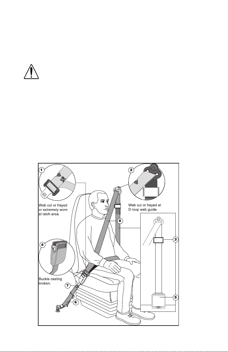
PART 5: SEAT AND RESTRAINT SYSTEMS
unusual wear, significant discoloration due to UV exposure, abrasion
to the seat belt webbing, or damage to the buckle, latch plate, retractor hardware or any other obvious problem should be replaced immediately, regardless of mileage.
WARNING! It is important to remember that any time a
vehicle is involved in an accident, the entire seat belt
system must be replaced. Unexposed damage caused
by the stress of an accident could prevent the system
from functioning properly the next time it is needed,
which could result in severe injury or even death.
One of the most critical areas to be inspected is the seat belt webbing. Constant movement of the belt ac tually means the webbing is
experiencing wear as it travels in and out of the retractor, through the
pillar loop web guide and through the various pieces of hardware
associated with the belt. The following guidelines detail how to
inspect for cuts, fraying, extreme or unusual wear of the webbing, etc.
and damage to the buckle, retractor, hardware, or other factors which
indicate that belt replacement is necessary.
03004
PB1328 —58— 22-02011 (R02/02)
Page 61

PART 5: SEAT AND RESTRAINT SYSTEMS
1. Check the web wear in the system. The webbing must be closely
examined to determine if it is coming into contact with any sharp or
rough surfaces on the seat or other parts of the cab interior. These
areas are typical pl aces where the web will experi ence cutting or
abrasion. Cuts, fraying, or excessive wear would indicate the need
for replacement of the seat belt system.
2. The D-loop web guide is the area where almost constant movement of the seat belt webbing occurs because of relative movement between the seat and the cab.
3. Check the comfort feature for cracks or possible damage and that
it works properly.
4. Check the buckle and latch for proper operation and to determine
if the latch plate is worn, deformed, or damaged.
5. Inspect the retractor web storage device, that is mounted on the
floor or B-pillar of the vehicle for damage. The retractor is the
heart of the occupant restraint system and can often be damaged
if abused, even unintentionally. Check retractor web storage
device operation to ensure that it is not locked up and that it spools
out and retracts webbing properly.
WARNI NG! Failure to adjust tether belts properly can
cause excessive movement of the seat in an accident.
This could lead to greater injuries for you. Tether belts
should be adjusted so that they are taut when the seat is
in its most upward and forward position.
6. If adjustable tethers are being used, be sure they are adjusted in
accordance with installation instructions. Tethers must also be
inspected for web wear, just as with the seat belt systems.
7. Mounting hardware should be evaluated for corrosion, and for
tightness of bolts and nuts.
8. Check web in areas exposed to ultraviolet rays from the sun. If the
color of the web in these areas is gray to light brown, the physical
strength of this web may have deteriorated due to exposure to the
sun’s ultraviolet rays; replace the system.
W ARNI NG! Replac e t he ent ir e belt sys t em (retr ac tor and
buckle side) if replacement of any one part is necessary.
Unexposed damage to one or more components could prevent the system fr om funct ioni ng properly the next time it is
needed, which coul d r esu lt in se ve r e inj ury or even dea t h.
If the inspection indicates that any part of the seat belt system
requires replacement, the entire system must be replaced, both
retractor and buckle side. An installation guide is attached to every
PB1328 —59— 22-02011 (R02/02)
Page 62

PART 5: SEAT AND RESTRAINT SYSTEMS
replacement belt. This set of instructions is entitled “
SEAT BELT INSTALLATION GUIDE.”
instruction guides for suspension and fixed bench seats. Use the
proper guide for your type of seat, and follow the instructions very
closely. It is vitally important that all components must be remounted
back in the same position as the original components that were
removed. This will maintain the design integrity of the mounting points
for the seat belt assembly.
Once the need for replacement of the seat belt has been determined,
be certain that it is only replaced with the recomm ended replacem ent
seat belt. The occupant restraint system has been developed and
tested specifically for this vehicle. If the vehicle was originally
equipped with a lap belt, it cannot be replaced with a three-point
shoulder harness system, because the cab mount ing points are not
structurally designed for a three-point seat belt.
There are separate seat belt
THREE-POINT
PB1328 —60— 22-02011 (R02/02)
Page 63

PART 6: DRIVER’S CHECKLIST
To keep your vehicle in top shape, and to maintain its high level of
safety for you, your passengers, and your load, make a thorough
inspection every day before you drive. You’ll save maintenance time
later -- and the safety checks could help prevent a serious accident.
Please remember, too, that Federal law requires a pre-trip inspection
and so do commercial trucking companies.
For more information, you can refer to Department of Transpor tation
Regulation 392.7 which tells you that interstate commercial motor
vehicles are not to be driven unless the driver is sure that certain
parts and accessor ies are in working order.
You aren’t expected to become a professional mechanic. The purpose of your inspections is to find anything that might interfere with
the safe and efficient transportation of yourself and your load. If you
do find something wrong and ca n’t fix it yourself, please have a qualified mechanic fix it right away.
Safe Vehicle Operation
For your safety, as well as those around you, be a responsible driver:
• If you drink, do not drive.
• Do not drive if you are tired, ill, or under emotional stress.
Much has gone into the manufacturing of your Peterbilt, including
advanced engineering techniques, rigi d quality cont rol, and d emanding inspections. These manufacturing proces ses will be enh anced by
you—the safe driver—who observes the following:
• knows & understands how to operate a vehicle and all its controls
• maintains the vehicle properly
• uses driving skills wisely
WARNING! Do not drink and drive. Your reflexes, perceptions, an d judgmen t can be affected by even a small
amount of alcohol. You could have a serious—or even fatal
accident—if you drive after drinking. Please do not drink
and drive or ride with a driver who has been drinking.
The use of alcohol, drugs, and certain medications will seriously impair perception, reactions, and driving ability.
These circumstances can substantially increase the risk of
an accident and personal injury.
The daily checks listed below are the foundation of your overall preventive maintenance program. See PART 8: MAINTENANCE AND
SERVICE for the complete preventive maintenance schedule for your
vehicle.
PB1328 —61— 22-02011 (R02/02)
Page 64

PART 6: DRIVER’S CHECKLIST
Approaching the Vehicle
1. Check the overall appearance and condition. Are windows, mirrors, and lights clean and unobstructed?
2. Check beneath the vehicle. Are there signs of fuel, oil, or water
leaks?
3. Check for damaged, loose, or missing par ts. Are there part s
showing signs of excessive wear or lack of lubrication? Have a
qualified mechanic examine any questionable items and repair
them without delay .
Checking U n d er th e H ood or Cab
1. With the engine stopped:
2. Check the engine oil level ; top up as necessary. Refer to your
engine’s operating manual for the type of oil to use.
3. Check the engine coolant level while the engine is cold. Top up as
necessary with premixed coolant. Refer to the instructions on
page 164
4. Check the engine belts. Refer to the instructions on page 165
check belt condition and adjust tension.
5. Check brake lines and hoses.
6. Check all other accessories, controls, belts, hoses, and wiring for
condition and adjustment.
7. Check the windshield washer fluid level; top up as necessary.
8. Check the power steering fluid reservoir; top up as necessary.
9. Check the steering components (pitman arm; draglink; power
steering hoses, etc.)
10.Drain the fuel/water separator.
Checking th e L u ggage Com p artment
1. Check the fire extinguisher charge.
2. Check the road emergency kit. Is it complete?
for adding coolant to the proper level.
to
PB1328 —62— 22-02011 (R02/02)
Page 65

PART 6: DRIVER’S CHECKLIST
Checking Ou tside the Vehicle
WARNI NG!
•
Diesel fuel in the presence of an ignition source (such as
a cigarette) could cause an explosion. You could be seriously injured. A mixture of gasoline or alcohol with diesel
fuel increases this risk of explosion.
recomme nd ed fo r your en gi ne.
•
Hot fuel vapors are combustible and can cause an
expl osion or fire result ing in injury or death. Do not
remove a fuel tank cap near an open flame.
1. Be sure all wheel studs and cap nuts are secure. Check wheel cap
nut torque weekly; refer to the instructions on page 139
2. Check tires for condition and proper inflation.
3. Check the front wheel bearing lube level.
4. Check parking (spring) brakes as to the condition and tightness
of air lines, breathers, clamp rings & bolts, mounting studs, and
release bolts.
5. Check turn signal operation.
6. Check emergency flashers and exterior lamps.
7. Check the fuel tanks. Is there enough fuel? Are the tank caps
secure?
8. Visually inspect the fuel tank mounting hardware. Are the tank
straps tight? Is the webbing in place?
9. Check the air cleaner and muffler(s). Are they tight and secure?
10. Check the trailer connections. Are they secure and the lines
clear? If they are not being used, are they stored properly?
11. Is the trailer spare wheel secure? Inflated?
12. Is the landing gear up and the handle secured?
13. Check the 5th wheel. Is the kingpin locked?
14. Is the sliding 5th wheel locked?
15. Check for loose or missing suspension fasteners.
16. Check springs or other suspension parts for damage such as
cracks, gouges, distortions, bulges, or chafing.
17. Check the air system. Are there lea ks?
18. Drain excess moisture from all air supply tanks. Make sure the
drain cocks are closed. This procedure is also required for air
supply tanks equipped with automatic drain valves.
Use only the fuel
.
PB1328 —63— 22-02011 (R02/02)
Page 66

PART 6: DRIVER’S CHECKLIST
In - Cab Checklist
CAUTION: To avoid injury while entering or leaving the
cab, keep your feet in contact with the steps and your
hands on the handhold. Always have three points of
contact as you enter or exit a cab. See PART 2: GET-
TING INTO AND OUT OF THE CAB AND FRAME
ACCESS of this manual for more information.
1. Adjust the seats.
2. Fasten and adjust safety restraint belts. See PART 5: SEAT AND
RESTRAINT SYSTEMS, or the Index, under Restraint
Systems 50.
3. Sleeper Restraints: Check and inspect condition. See PART 5:
SEAT AND RESTRAINT SYSTEMS, or the Index, under Restraint
Systems 50.
4. Adjust the steering column.
5. Check mirror adjustment.
6. Operate air-powered devices to circulate lubricants.
NOTE: The previously-mentioned items should be checked
daily, as a minimum. They ar e in addition to, not in place
of Federal Motor Carrier Safety Regulations. These may be
purchased by writing to:
Superintendent of Documents
U.S. Government Printing Office
Washington, DC 20402
PB1328 —64— 22-02011 (R02/02)
Page 67

PART 7: STARTING & OPERATING THE VEHICLE
Since each Model 387 is custom-equipped, all engine operation
instructions in this manual are general. You will want to consult the
manual for your engine to find out details about your specific engine’s
needs. You may need to use a slightly different procedure from the
one outlined here.
Also check the ATA Truck Driver’s Handbook in your glove box. It will
give you tips on starting, shifting, and driving a truck.
Below are instructions for both nor m al-temp erature starting and co ldweather starting.
Normal Starting Procedure (Normal Temperature)
When the outside temperature is above 50° F (10° C), you can use
the following procedure.
1. Set the parking brake.
2. Put your main transmission in Neutral.
3. Disengage (depress) the clutch (with manual transmission).
4. Tur n the key switch to ON.
• If your vehicle is equipped with a digital message center (DMC),
the DMC display will come on in the “Clock” mode.
• The multipl ex instrumentation syste m wil l begin a self-te st:
-Gauge pointers will move to a 12:00 position, with their LED
warning lights on, for 5 seconds.
-Gauge pointers will then move to their actual gauge readings
and their LED warning lights will go off.
• The speedometer mes sa g e center (SMC) w ill dis play the odome -
ter.
NOTE: If the SMC displays other messages or if other alarms
activate after the key is turned ON, see the “Warning Alarms”
section at the end of this part on page 96
5. Turn the key to start.
.
CAUTION: Never operate the starter motor while the
engine is running. The starter and flywheel gears could
clash or jam, severely damaging them.
NOTE: Some starters are equipped with overcrank protection.
Check the “Engine Operation and Maintenance Manual” for
details.
If the engine does not start within 30 seconds, release the starter but-
ton. To avoid overtaxing the start er motor or the batteries, don’t use
PB1328 —65— 22-02011 (R02/02)
Page 68

PART 7: STARTING & OPERATING THE VEHICLE
the starter for more than 30 seconds. Let the start er motor cool an d
the batteries recover for 2 minutes before trying again.
If the engine still won’t star t a fter a couple of tries, check the manual
override shutdown valve and fuel lines for possible fuel starvation or
air leaks. Starting failure may mean fuel isn’t reaching the injectors.
6. As soon as the engine starts, begin to watch the oil pressure
gauge. Check your engine manufacturer’s manual for the right
pressure for your engine. If the oil pressure doesn’t rise within a
few seconds, stop the engine. Find out what is wrong before
restarting the engine.
7. Slowly engage (release) the clutch after the engine has started.
8. Wait until normal engine oil pressure registers on the gauge before
idling or accelerating the engine beyond 1000 RPM.
NOTE: If your vehicle has a DDC engine, and if it has not
been started for more than 30 days, squirt about half a cup
(120 ml) of clean, specified engine oil into the turbocharger
oil inlet port. Use an oil can. This will keep the turbocharger
bearings lubricated until the engine oil pressure gets up to
normal.
Cold Te m perature Starting Procedure
In cold weather, fast engine starting helps relieve the loads on the
electrical system and cranking motor. Using the special cold starting
equipment will help starting. If you follow a f ew simple guidelines, you
will extend the service life of your engine.
•Keep the electrical system in top condition.
•Use the best quality fuel of the recommended grade.
•Use recommended engine lubricating oil.
Engine Warmup
The pur pose of engine warmup is to allow oil film to be established
between pistons and liners, shafts and bearings while your engine
gradually reaches operating temperature.
Warmup Procedure
1. After you’ve started your engine, idle it at approximately 600 RPM
while you check
•oil pressure
•air pressure
•alternator output
PB1328 —66— 22-02011 (R02/02)
Page 69

PART 7: STARTING & OPERATING THE VEHICLE
2. After a few minutes of idling at 600 RPM, increase your idle speed
to 900 or 1000 RPM. Continue your warmup. This procedure
allows oil to warm and flow freely while pistons, liners, shafts, and
bearings expand slowly and evenly. In extremely cold temperatures, you may have to increase idle speed.
NOTE: In colder climates where the temperature is often
below freezing, the warmup for turbocharged engines is
especially important. Chilled external oil lines leading to the
turbocharger will slow the oil flow until the oil war m s, reducing oil available for the bearings. Watch the engine oil temperature or pressure gauge for a warming trend before
increasing engine idle speed (RPM).
3. Continue the engine warmup until the coolant temperature
reaches at least 130° F (54° C). At this temperature, you can use
partial throttle. Wait until the coolant temperature is at least 160° F
(71° C) before operating at full throttle.
WARNING! Exhaust fumes from the engine contain carbon
monox ide, a color l es s and odo r les s gas . Do no t breat he the
engine exha ust gas . A poorly maintained , dama ged or corroded e xha ust sy ste m can al lo w car bon monoxide to enter
the cab or slee per. Entry of carbon mono xi de into the cab is
also pos sib le from other vehicles n ear b y. Fail ure to properly
maintai n yo ur vehic le cou ld caus e carbo n mono xide to ente r
the cab/sleeper and causes serious illness.
CAUTION: Never idle y our vehic le for prolonged periods of
time if you sense that exhaust fumes are entering the cab
or sleeper . In vestigat e the cause of the fu mes and correct it
as soon as possible. If the vehicle must be driven under
these conditions, drive only with the windows slightly
open. Failure to repair the source of the exhaust fumes may
lead to personal harm.
NOTE: Keep the engine exhaust system and the vehicle’s cab/
sleeper ventilation system properly maintained. It is recommended
that the vehicle’s exhaust system and cab/sleeper be inspected
•
By a competent technician every 15,000 miles
•
Whenever a change is noticed in the sound of the
exhaust system
•
Whenever the exhaust system, underbody, cab or
sleeper is damaged
PB1328 —67— 22-02011 (R02/02)
Page 70

PART 7: STARTING & OPERATING THE VEHICLE
NOTE: Do not stay in the vehicle with the engine running or
idling for more than 10 minutes with the vehicle’s Heater and
A/C ventilation system in RECIRC or at LOW FA N SPEED.
Even with the ventilation system On, running the engine
while parked or stopped for prolonged periods of time is not
recommended.
NOTE: If other vehicles are parked next to you idling, move
your vehicl e or do not stay in your vehic le f or prolonged periods
of time.
CAUTION: The use of a winterfront can result in excessive
engine coolant, oil, and charge air (intake) temperatures,
which can lead to overheating and possible engine dam-
age. If you must use a winterfront, refer to the “Engine
Operation and Maintenance Manual” for operating r estrictions and recommendations.
Transmission Warmup
In cold weather you may find shifting sluggish when you first sta rt the
engine. Transmission warmup is especially important at this time, but
it is always a good idea to warm up your transmission before starting
out on the road.
To warm up the transmission lubricating oil during engine warmup,
with a single transm is sion:
• Check that the transmission is in Neutral.
• Release the clutch pedal.
If you have a two -transmissi on combination:
• Put the main transmission in gear.
• Put the auxiliary transmission in N eu t ra l. This w ill allow the trans -
mission countershaft to turn, agitating the oil and warming it.
Idling the Engine
Under most circumstances, idling your engine for long periods merely
wastes fuel. In severe arctic weather conditions, however, you may
need longer idling to be sure all parts of your engine are fully lubricated.
PB1328 —68— 22-02011 (R02/02)
Page 71

PART 7: STARTING & OPERATING THE VEHICLE
WARNING! To reduce the chance of personal injury and/or
vehicle damage from overheated engines, which can result
in a fire, never leave the engine idling without an alert
driver present. If the engine should overheat, as indicated
by the engine coolant temperature light, immediate action
is required to correct the condition. Continued unattended
operation of the engine, even for a short time, may result in
During the time it takes you to drink a cup of coffee, your engine can
cool as much as 60° F (33° C) below nor mal operating temperature.
To keep the engine warm dur ing a short break , turn it off. An d don’t
allow your engine to idle longer than five minutes.
Putting The Vehicle In Motion
This section discusses t he clutch and transmission operation to get
your Model 387 underway.
serious engine damage or a fire.
CAUTION: Do not allow your engine to idle, at low rpm
(400–600 rpm), longer than five minutes. Long periods of
idling after the engine has reached operating temperatures
can decrease engine temperature and cause gummed piston rings, clogged injectors, and possible engine damage
from lack of lubrication. The normal torsional vibrations
generated can also cause transmission wear.
W ARNI NG! D o not ca rr y loo se ob jec ts i n your cab, it ca n be
dangerous. In a sudden stop, or even going over a bump in
the road, they could fly through the air and strike you or a
passenger. Y ou coul d be inj ur ed or ev en kill ed. Secur e al l
loose objects in the cab before moving the vehicle.
Shifting The Transmission
You will find a shift pattern either on a decal in your cab or on a
medallion in the shift knob. Check to be sure you know the correct
sequence for your particular transmission. Re fer to the transmission
manual included with your vehicle for complete instructions in the
operation of your transmission.
Shifting Gears in a New Vehicle
Shift carefully in a new vehicle. The transmission m ay be a little stiff
at first. So be careful to avoid gear clashing.
When you are operating a new vehicle or one that has been exposed
to cold weather, you want the transmission lubrican t to circulate and
coat the contacting surfaces of the gears. Metal contacting metal in
moving parts may seriously damage your transmission. So don’t
drive in one gear for long until the transmission lubricant has had a
chance to coat those contacting surfaces.
PB1328 —69— 22-02011 (R02/02)
Page 72

PART 7: STARTING & OPERATING THE VEHICLE
Operatin g th e C l u tch
“Rid ing” th e C lutch
The clutch pedal is not a footrest. Driving with your foot on the clutch
pedal will allow your clutch to slip, causing excessive heat and wear.
You can damage your vehicle this way .
Clutch Travel
CAUTION: Always use first gear or a low speed range to
start the vehicle in motion. The use of a higher gear or
speed range forces undue strain on the engine, clutch,
other transmission components, and may cause damage.
To put your vehicle into motion, push d own on the clutch pedal until
the clutch brake makes contact. This contact will occur at about 1/2
inch to 1 inch from the end of pedal stroke. Select a gear low enough
to let your vehicle start forward with the throttle at idle until the clutch
is fully engaged.
The total stroke of the clutch pedal is about 10 inches. The first 1 3/4
to 2 inches is free travel. After that is the release stroke, the part that
fully releases the clutch. The last 1/2 to 1 inch engages the clutch
brake. If your vehicle is new, watch the free travel in your clutch carefully for the first few hundred miles. As your clutch lining wears and
high spot s get worn smo oth, you will get les s fre e travel.
Always start out in a low gea r with a c eramic-faced clutch. S tarting in
higher gears, even with a light load, will cause a very j umpy star t an d
excessive wear. And don’t allow your vehicle to roll in the opposite
direction at all during clutch eng agement. If you need to start up on
an incline, apply your service brakes before you release the parking
brake. Then release your service brakes as you engage the clutch
and apply throttle.
Release Bearing Wear
When you must idle your engine for any period of time, shift your
transmission to neutral and engage the clutch (take your fo ot off the
pedal). This helps prevent unnecessary wear of your clutch release
bearing. And it is less tiring for you, too.
Clutch Adjustment
Inspect manual and self-adjusting clutches reg ularly to maintain correct clutch adjustment. Have your dealer’s service depar tment perform any adjustments necessary. Do not adjust your clutch by
adjusting the external linkage without first checking (and correcting if
necessary) the internal clutch adjustment. Using only the external
linkage adjustment could damage the clutch.
PB1328 —70— 22-02011 (R02/02)
Page 73

PART 7: STARTING & OPERATING THE VEHICLE
Clutch Brake
Your clutch brake is used for stopping gear rotation to let you shift into
1st gear or reverse when your vehicle is at a standstill.
About the last 1/2 to 1 inch of clutch pedal travel activates your clutch
brake. So if you are stopped and want to shift directly into 1st or
reve rse, depress the clutch pedal until contact with the clutch brake is
made to stop transmission gear rotation.
If you have a butt-tooth condition and can’t shift the transmission,
gradually release the clutch. Then the drive gear can roll enough to
allow the teeth to line up properly and complete the shift.
CAUTION: Be careful not to apply the cl utch brake while
the vehicle is moving. The purpose of the clutch brake
is to stop the transmission so that you can shift into a
starting gear without grinding. Applying the clutch
brake when the vehicle is moving causes a braking
effect on the entire vehicle. This wear naturally shortens the service life of your clutch brake.
Double Clutching
Whether you are upshifting or down shifting, it is best to double
clutch. Double clutching is easier on your transmission and on your
engine, helping your vehicle match engine speed with driveline speed
and achieving clash-free shifts. To double clutch:
1. Push down the clutch pedal to disengage the clutch.
2. Move the gear shift lever to neutral.
3. Release the pedal to engage the clutch. This lets you control the
RPM of the mainshaft gears. Thus you can match the RPM of the
mainshaft gears to those of the output shaft.
Upshifts - Let the engine and gears slowdown to the RPM
required for the next gear. Use the tachometer to determ ine optimum RPM for gear engagement.
Downshifts - Press accelerator to increase engine and gear
speed to the RPM required in the lower gear. Use the tachometer
to determine optimum RPM for gear engagement.
4. Now quickly press the pedal to disengage the clutch. Move the
gear shift lever to the next gear speed position.
5. Release the pedal to engage the clutch.
PB1328 —71— 22-02011 (R02/02)
Page 74

PART 7: STARTING & OPERATING THE VEHICLE
Interaxle Differential
On vehicles with tandem rear axles, the interaxle differential allows
each axle to turn independent ly. Differential action between the tandems relieves stress on the rear axles and tires and provides better
performance.
When operating normally on paved, dry su rfaces, keep your truck’s
interaxle differential in the UNLOCK position.
SHIFT AT ANY SPEED EXCEPT
IF A WHEEL IS SPINNING
03029
Switch In Unlock Position
In the LOCK position, continuous operation on a paved, dry surface
stresses the tandem axles, possibly causing internal damage to them.
Shift into the LOCK position to operate on slippery surfaces like
• Ice or snow - with or without tire chains.
• Dirt roads.
• Loose sand, mud, or other off-road conditions.
Switch into LOCK when checking performance on a chassis dynamometer.
WARNING! Do not put the differential lock in the LOCK
position while the wheels are spinning freely (slipping),
you could lose control of the vehicle or cause axle dam-
age—you could be injured. Switch to LOCK only when
the wheels are not spinning.
WARNI NG! Do not operate the vehicle on dry pavement
with the differential locked; it could lead to an injury
accident. On dry pavement, you will not be able to steer
well with the differential locked. Lock the differential
only when operating on surfaces with poor traction,
such as wet, slippery roads or loose gravel.
PB1328 —72— 22-02011 (R02/02)
Page 75

PART 7: STARTING & OPERATING THE VEHICLE
WARNING! Do not use the differential lock during
downhill operation or at speeds above 25 mph (40 km/
h). When it is engaged under these conditions, your
vehicle will exhibit “understeer” handling characteristics. This “understeer” condition will cause your vehicle
to not turn as quickly and more steering effort will be
required, which can cause an injury accident.
To reduce load o n the drive train, ease up on the t hrot tle pedal wh enever you shift into LOCK or UNLOCK.
Dual Range (Two Speed) Axles
If you have this option, dual range axles provide two rear axle ratios
for operating under heavy loads or off-highway as well as for over the
road trucking. The Low range provides m aximum torque for off -road
work. The High range is a faster ratio for highway speeds and conditions.
A switch on your instrument panel controls this function. You will
notice that it has a guard to protect you from activating it accidentally.
.
2
03030
Range Selector
Here’s how to use your dual range axle:
WARNI NG! Never shift the axle when moving down hill.
Engine driveline disengagement may occur, eliminating
engine retardation and allowing the wheels to spin
faster than the current speed of the engine. This may
require severe braking to slow the vehicle down and can
result in an injury accident.
1. Unlock the interaxle differential before starting.
2. Put the Range Selector in the LOW range. Shift the transmission
to start the truck moving.
3. Off-Highway: When you are driving on rough terrain and secondary roads, or under a very heavy load, keep the axle in the LOW
range. Shift your transmission to maintain the road speed you
want.
PB1328 —73— 22-02011 (R02/02)
Page 76

PART 7: STARTING & OPERATING THE VEHICLE
4. When you go from off-highway to highway driving, shift the axle to
the HIGH range this way:
• Be sure the differential is UNLOCKED.
• Keep the accelerator down and move the Range Selector lever to
HIGH.
• Keep driving with the accelerator down until you want the axle to
shift.
• Then release the accelerator until the axle has shifted.
• You are now in the HIGH axle range on the highway. Shift the
transmission normally to reach your desired cruising speed.
5. If you need to downshift the axle for more power:
• Keep the accelerator down and move the Range Selector lever to
LOW.
• Keep driving with the accelerator down until you want to downshift
the axle.
• Then release and depress the accelerator pedal quickly to
increase the engine RPM.
• The axle will shift to the LOW range.
Important Ti ps on Operating Your Dua l R ange Axle
NOTE: If your vehicle has an automatic transmission, it ma y
be necessary to shift it to the Neutral position momentarily to
allow the main differential lock splines to fully engage or disengage.
• To avoid damaging your vehicle, shift the axle at a slower speed
until you are used to driving with the dual range axle.
When you are driving on a surface with good traction, keep the interaxle differential unlocked. You can drive with the axle in the LOW or
HIGH range.
SHIFT AT ANY SPEED EXCEPT
IF A WHEEL IS SPINNING
03029
Inter a x l e In U n l ock
PB1328 —74— 22-02011 (R02/02)
Page 77

PART 7: STARTING & OPERATING THE VEHICLE
• When you are driving with poor traction, lock the differential. When
you have the differential locked, drive with the axle in LOW range
only.
SHIFT AT ANY SPEED EXCEPT
IF A WHEEL IS SPINNING
03029A
Inter a x l e In L o ck
• Always UNLOCK the interaxle differential before shifting the axle
speed range.
CAUTION: If you shift the axle range with the interaxle
differential in LOCK, you could do serious damage to
your axles. Never shift the axle range with the differential locked.
• Park the truck with the Range Selector in LOW.
Automated Transmissio n
An automated transmission makes shifting much easier, of course.
But because your truck pulls a heavy load, if you have such a transmission, it is important to use it efficiently. For correct operation, see
the manual for your automated transmission included with your vehicle.
WARNI NG! If your vehicle has a Freedomline™ transmission, be aware that it can roll backwards when
stopped on a hill or grade, or when starting from a stop
on a hill or grade. This could cause serious damage or
personal injury. Observe the following guidelines:
•When stopped on a hill or grade, press the brake pedal.
•When starting from a stop on a hill or grade, quickly
remove your foot from the brake pedal and firmly press
on the accelerator pedal.
PB1328 —75— 22-02011 (R02/02)
Page 78

PART 7: STARTING & OPERATING THE VEHICLE
Auxiliary Transmission
If you have an auxiliary transmission, see your transmission manufac-
turer’s manual for its proper operation.
If Your Vehicle Must Be To wed
CAUTION: Remove the driveline and axle shafts or lift
the driving wheels off the ground before towing the
vehicle. You could seriously damage your vehicle by
towing it with the driveline connected and the drive
wheels on the ground. Worse, when vehicles are towed
either by wrecker or piggy-back, the lubricant in the top
front of the drive axle will drain to the rear. This will
leave the top components dry. The resulting friction will
seriously damage them. Always remove the main driveshaft and axle shafts before towing your vehicle.
Returning a Towed Vehicle to Service
You will have to add lubricant to prevent damage after your vehicle
has been towed.
1. Into the pinion cage, add 1 pint (.47 liter) of lubricant.
or
Into the inter-axle differential, add 2 pints (.94 liter) of lubricant.
See the Index, under Lubricant Specifications, for the lubricant
required by each axle.
2. After adding the specified type and amount of lubricant, drive the
vehicle. It should be unloaded. Drive 1 to 2 miles (1.5 to 3 km) at
a speed lower than 25 mph (40 km/h).
This will thoroughly circulate the lubricant through the assembly.
Anti-Lock Braking System Operating Information
A Model 387 is equipped with an anti-lock braking system (ABS). This
ABS reduces the possibility of whe el lock-up. If a wheel is about to
lock during braking, the ABS will autom atically adjust air pressure to
the brake chambers on the appropriate wheel(s) to prevent wheel
lock-up. The ABS is automatically turned on when the ignition switch
is turned on.
WARNI NG! The brake system is a critical vehicle safety
system. For the safety of you and others around you,
have the vehicle submitted for periodic preventive maintenance checks as well as having any suspected problems immediately checked by an Authorized Service
Center. Failure to properly maintain your brake system
can lead to serious injury accidents.
PB1328 —76— 22-02011 (R02/02)
Page 79

PART 7: STARTING & OPERATING THE VEHICLE
WARNING! Do not drive through water deep enough to
wet brake components, as it may cause the brakes to
work less efficiently than normal. The vehicle’ s stopping
distance may be longer than expected, and the vehicle
may pull to the left or right when brakes are applied,
which could contribute to an accident.
WARNING! Do not rel y on an anti-lock br ake system that is
functioning improperly. You could lose control of the vehicle resulting in a severe accident and personal injury. If an
ABS lamp goes on while you are driving or stays on after
the self-check, that anti-lock system might not be working.
The ABS may not function in an emergency. You will still
have conventional brakes, but not anti-lock brakes. If any
warning lamp indicates a problem, have that ABS checked.
ABS Warning Lamps
Truck/Tractor ABS Warning Lamp
A truck/tractor ABS warning lamp illuminates when the ignit ion switch
is first turned on and will remain on until the system self-test has been
completed successfully. Normally, this ABS lamp will remain on until a
speed of no more than 9 mph has bee n reached and the speed sensors have been checked fo r correct output. The lamp should remain
off after this point unless a problem in the system is detected.
CAUTION: If the truck/tractor ABS warning lamp does
not illuminate when the ignition is first turned on, there
is a problem with the bulb or wiring. The driver should
have this checked as soon as possible.
The truck/tractor ABS lamp is located in the warning lamp cluster.
(See illustration on page 42
.).
ABS
02999A
PB1328 —77— 22-02011 (R02/02)
Page 80

PART 7: STARTING & OPERATING THE VEHICLE
Trailer ABS Warning Lamp
Trucks, tractors, and trailers built on and after March 1, 2001 are
equipped with power line communication (PLC) per U.S. FMVSS 121,
including a PLC Trailer ABS warning lamp in the cab (see page 42
):
ABS
CAUTIO N: If the traile r ABS warning lamp does not illuminate when the ignition is first turned on, there is a
problem with the bulb or wiring. The driver should have
this checked as soon as possible.
NOTE: A successsful warning lamp illumination and bulb
check at ignition on does not
be connected to has trailer ABS. You should personally
inspect every trailer to determine its braking system.
A trailer ABS warning lam p will illuminate for a bulb check when the
ignition switch is first turned on - whether or not a trailer is connected
to the vehi cle. If th e bulb ch eck is satisfact ory, the lamp w ill next do
either of the f ol l owi ng:
1. If no trailer is connected, or if a non-ABS-equipped trailer is connected, the trailer ABS lamp will go off after a few seconds.
indicate that the trailer you may
NOTES:
•
A “properly connected” ABS-equipped trailer is
-a trailer with PLC hooked up to the J560 connector
-a trailer without PLC that is hooked up to an optional
ISO 3731 connector
•
For doubles or triples: PLC does not distinguish between
trailer s. An ABS problem in an y trailer will activate the
traile r ABS w a rni ng lamp.
2. If an ABS-equipped trailer is properly connected, the trailer ABS
warning lamp will remain illuminated for a few more seconds while
the trailer A BS is tes ted.
• If no trailer ABS problems are detected, the lamp will go off.
• If a trailer ABS pr oble m is d etected, the la m p w ill re m a in on . The
driver should have the trailer’s ABS problem corrected before the
vehicle is driven with that trailer attached.
PB1328 —78— 22-02011 (R02/02)
Page 81

PART 7: STARTING & OPERATING THE VEHICLE
Wheel Spin Control Warning Lamp
Your truck/tra ctor ABS ma y ha ve an accel erati on sli p regulation (ASR)
or automatic traction control (ATC) feature. This feature is controlled
by a switch as shown in the next illustration. Either of these features is
monitored by a warning lamp located on the main dash.
.
I
ATC
0
03034
The Wheel Spin C ontrol war ning lamp will br iefly illuminate and then
go out when the ignition switch is first turned on. The Wheel Spin
Control warning lam p will illuminate whenever the ASR or AT C system detects drive wheel spin. The lamp will remain illuminated as long
as wheel spin is detected and the ASR or AT C system is app lying the
drive wheel brakes or reducing engine torque. Do not allow the Wheel
Spin Control lamp to remain on continuously for an extended length of
time. Extended continuous use of the ASR / ATC can cause overheating of the drive wheel brakes. Engine torque or vehicle speed should
be reduced to eliminate wheel spin and prevent excessive application
of the ASR / ATC system. Excep t for checking for proper illumination
of the ABS and Wheel Spin Control warning lamps when first star ting
the truck, and for monitoring these lamps while driving, no special
operating procedures are required. For a detailed system description,
see service literature for your specific ABS that was provided with
your vehicle.
Brake Safety and Emergency
WARNING! Do not operate the vehicle in the event of a
malfunction in any air circuit. The vehicle should not be
operated until the system is repaired and both braking
circuits, including all pneumatic and mechanical components, are working properly. Loss of system air can
cause the service brakes not to function resulting in the
sudden application of the spring brakes causing wheel
lock-up, loss of control, or overtake by following vehicles. You could be in an accident and severely injured.
PB1328 —79— 22-02011 (R02/02)
Page 82

PART 7: STARTING & OPERATING THE VEHICLE
WARNING! Unless you have an anti-lock braking system, always avoid completely depressing the service
brake pedal, if possible, even during emergency braking. Depressing the brake pedal too aggressively can
cause the wheels to lock, which can lead to an uncontrolled skid and could cause an accident.
To stop your vehicle in an emergency, vary the s ervice brake application pressure to provide maximum braking force without locking the
wheels. Use engine compression to assist the ser vice brakes; i.e.,
don’t depress the clutch pedal until the engine reaches idle speed.
Overh eated Brakes
Under normal braking condi tions, the energy generated will brin g the
internal brake drum temperature to about 500° F (260° C). This is
well within the safe zone: The maximum safe temperature of linings
for drum type brakes is usually about 800° F (427° C).
But if service brakes are used i mproperly or for prolonged periods,
internal brake drum temperatures may commonly exceed 800° F
(427° C). Such brake overheating may be detected by a burning
smell or smoke coming from a drum. If this occurs, you should immediately stop and check for cracked brake drums or lining fires. If neither exists, get back behind the wheel and resume a slow speed as
soon as possible to cool the brakes.
Parking Brakes and Their Use
The yellow diamond-shaped knob on your instrument panel cont rols
your parking brakes. These are spring brakes which you activate by
releasing air pressure from their chambers. When they are not in use,
air pressure compresses the springs and releases the brakes. But
putting the valve in the “Park” position exhausts air from the chambers
and allows the spring s to extend and apply the brakes. Also, if your
system air drops below the safe operating level, the spring brakes will
apply automatically, bringing your vehicle to a stop.
WARNI NG! On trailers buil t bef ore March 1975 you may
not have parking brakes if the trailer reservoir pressure
leaks down. If you depend on them to hold your vehicle,
they could release, causing a serious accident. These
older trailers have emergency brakes not designed for
parking. They will apply only if there is enough trailer
reservoir pressure. Don’t use your trailer emergency
brakes for parking. Apply your tractor parking valve
too.
PB1328 —80— 22-02011 (R02/02)
Page 83

PART 7: STARTING & OPERATING THE VEHICLE
0290
Red / Yellow Controls
WARNING! Do not leave the cab without applying the
parking brake. The truck could roll and cause an injury
accident. Always apply the parking brake before you
leave the cab.
WARNING! Stopping with the parking brake controls
can cause a sudden wheel lock-up, loss of control, or
can cause you to be overtaken by following vehicles.
You cou ld be severely injured. Never pull out the parking brake valve while the vehicle is moving.
WARNING! Do not use the trailer hand brake or service
brakes to park and hold an unattended vehicle—use the
parking brakes. Because service brakes work with air
pressure, these brakes could slowly release. Your vehicle could roll, causing a serious accident. Someone
could be hurt or killed. Never rely on the service brakes
to hold a parked vehicle.
WARNING! Never drive your vehicle with the parking brake
applied. Always release the parking brakes prior to moving
the vehicle. Failure to disengage the parking brakes prior
to moving your vehicle could result in excessive heat buildup in the brake system, resulting in a fire.
NOTE: Today’s diesel electronic engines have significant
torque and startability power at low RPM. Combinations of
engine speed and available torque may over-power the vehicle’s parking brakes.
To apply all your parking brakes, pull the yellow knob Out. The parking brakes will set. And the trailer air supply valve (red octagon knob)
will automatically pop out, releasing air pressure and setting the trailer
brakes.
PB1328 —81— 22-02011 (R02/02)
Page 84

PART 7: STARTING & OPERATING THE VEHICLE
CAUTION: Do not try to put th e vehicle in motion bef o r e
pressure in the system reaches 100 psi (689 kPa)
because the wheels are locked by the spring brake
action. Unnecessary stress and possible brake malfunction could occur if the vehicle is forced to move before
the air system reaches 100 psi (689 kPa).
To release y our vehi cl e’s brakes ONLY, push in the yellow knob. Your
trailer will remain parked.
• To release the t raile r brak es ONLY, push in the re d knob . The v ehicle
will remain parked.
• To release the full combinat i on of brakes, push in BOTH y ellow and
red knobs.
Trailer Air Supply Valve
The red octagon knob controls the air su ppl y to the tr ail er.
To supply air to th e tr ailer syst em an d releas e the t rai ler parking br a kes :
• Allow the tractor air system pressure to build up to operating level.
• Push the red knob in.
• Hold the red knob in by hand until the trailer air pressure builds to
a pre-set level, about 45 psi. At this point it will rem ain in.
The yellow knob will remain out; the tractor will remain parked. If you
ever have a failure or disconnect of the air supply hose to the trailer,
the trailer parking brakes will set. The red kno b wil l autom at ically pop
out and seal off the tractor air reser voirs to protect the tractor air sys-
tem pressure. When operating the tractor “bobtail,” the red knob must
remain out to protect the tractor air system pressure
PB1328 —82— 22-02011 (R02/02)
Page 85

PART 7: STARTING & OPERATING THE VEHICLE
Manually Re le asing Spr ing B r akes
You may sometime have to release your vehicle’s spring brakes by
hand to allow the vehicle to be towed. This could happen if the system air pressure doesn’t reach operating pressure because your
engine or compressor is not working properly. You will have to
release the spring brakes at the spring brake chambers.
WARNING! Do not operate a vehicle when the spring
brakes have been released manually. Driving a vehicle
that has had its spring brakes manually released is
extremely dangerous. You would probably have no
brakes at all. You could have a serious or fatal accident.
WARNING! Releasing the spring brakes on an unsecured vehicle could lead to an accident. The truck could
roll, causing severe injury . Always secure the truck with
wheel chocks, chains, or other safe means to prevent
rolling before manually releasing the spring brakes.
WARNING! Disassembling the spring brake chamber is
dangerous and could cause serious injury. These
chambers contain a powerful spring that is compressed.
Sudden release of t his spring could cause you to be
badly injured. Do not disassemble a spring brake chamber.
NOTE: The primary purpose of the manual release feature
is to permit the vehicle to be towed to a repair facility.
PB1328 —83— 22-02011 (R02/02)
Page 86

PART 7: STARTING & OPERATING THE VEHICLE
To release spring brakes manually:
1. Remove the cap from
the spring chamber.
2. Remove the release
stud assembly from
the side pocket;
remove the release
nut and washer from
the release stud.
3. Slide out the release
stud.
02936
PB1328 —84— 22-02011 (R02/02)
Page 87

PART 7: STARTING & OPERATING THE VEHICLE
4. Insert the release stud
through the opening in
the spring chamber
where the cap was
removed. Insert it into
the pressure plate.
Turn the release stud
1/4-turn clockwise in
the pressure plate; this
secures the cross pin
into the cross pin area
of the pressure plate &
locks it into the manual
release position.
5. Assemble the release
stud washer and nut
on the release stud.
6. WIth a wrench, turn the
release stud assembly
nut until the compression
spring is 90% - 95%
caged. While doing this,
ensure the push rod
(adapter push rod or ser vice push rod) is retract ing. Do not overtorque
the release stud assem bly. (S-Cam type maxi mum 50 lb.-ft., Wedge
type ma x i mu m 30 lb.-ft.)
The spring brake is now
mechanica lly released.
PB1328 —85— 22-02011 (R02/02)
02937
Page 88

PART 7: STARTING & OPERATING THE VEHICLE
Retarders
Various retarders are available which function against the engine,
driveline, or transmission. These are devices that use your engi ne’s
power to slow down your vehicle. They save wear and tear on your
service brakes and can be a safety feature, too, because they can
keep your brakes from overheating.
Ideally, you should always slow your vehicle with your retarder (where
permitted by law) and use your ser vice brakes only for stopping completely. Operating this way will greatly prolong the life of your brakes.
WARNI NG! In an emer gency, the retarder might not stop
you fast enough to prevent an accident. You could be
badly hurt if you relied only on your retarder. Use the
service brakes for quick stops. The retarder is not an
emergency brake.
WARNING! The retar der is NOT intended as the primary
brake for the vehicle, nor is it an emergency brake. The
retarder only helps the service brakes by using pressure
to slow the drivetrain. Use the service brakes for quick
stops.
WARNING! The service brakes must be used in an
emergency. The retarder alone might not stop you fast
enough to prevent an accident. You could be badly hurt
if you relied only on the retarder.
WARNING! Do not use the retarder when operating on
road surfaces with poor traction (such as wet, icy, or
snow covered roads or gravel). Retarders can cause the
wheels to skid on a slippery surface. You could lose
control of the vehicle if the wheels begin to skid, resulting in an accident.
Driving Bobtail or with an Unloaded Trailer
Do not use your engine retarder to slow down when you are bobtailing
or pulling an empty trailer.
WARNING! Using an engine retarder can cause a wheel
lockup. The trailer is not loading the tires enough to
give the traction you may need. When you are bobtail or
unloaded, you can have a serious accident if your
wheels lock suddenly during bra k in g. You could be
injured. Don’t use your retarder when you are driving
bobtail or with an unloaded trailer.
PB1328 —86— 22-02011 (R02/02)
Page 89

PART 7: STARTING & OPERATING THE VEHICLE
Pyrometer
Maintaining Correct Operating Temperature
The optional pyrometer indicates engine exhaust gas temperature.
Because it responds almost immediately to changes in exhaust temperature, the pyrometer is an excellent indicator of engine output.
If you watch engine speed and exhaust temperature ranges, the
pyrometer can help you operate your truck more efficiently and avoid
sudden changes in engine operating temperature.
CAUTION: Do not allow the pyrometer reading to
exceed the specified maximum operating temperature.
If the pyrometer has no label specifying the maximum
operating temperature for the pyrometer, contact your
engine distributor for a recommendation.
NOTE: Different size injectors or changes in altitude may
affect engine operating and exhaust temperatures.
Procedure For Reducing High Pyrometer Temperature Readings
1. If the pyrometer indicates excessive temperature, ease up slightly
on the throttle.
2. If RPM and speed drop, downshift one gear to help lower the
exhaust temperature.
3. Observe the pyrometer reading. If the temperature continues to be
high, continue downshifting until acceptable operating temperatures can be maintained.
Stopping The Engine
Before Stopping The Engine
A hot engine stores a great amount of heat, and it doesn’t co ol down
immediately after you shut it off. Always cool your engine down
before shutti ng it of f. You will g r ea tl y incre ase its ser v ic e li fe.
Idle the engine at 1000 RPM for five minutes. Then low idle for th irty
seconds before shutdown. This will allow circulating coolant and
lubricating oil to carr y away heat from the cylinder head, valves, pistons, cylinder liners, turbocharger, and bearings. This way you can
prevent serious engine damage that may result from uneven cooling.
Turbochargers
This cooling-down practice is especially impor tant on a turbocharged
engine. The turbocharger contains bearings and seals that are subjected to hot exhaust gases. While the engine is operating, heat is
PB1328 —87— 22-02011 (R02/02)
Page 90

PART 7: STARTING & OPERATING THE VEHICLE
carried away by circulating oil. If you stop the engine suddenly after a
hard run, the temperature of the turbocharger could rise as much as
100°F (55°C) above the temperature reached during operation. A
sudden rise in temperature like this could cause the bearings to seize
or the oil seals to loosen.
Refuel Before the Final Stop
Air space in your fuel tanks a llows water to condense there. To prevent this condensation while you are stopped, fill your tanks to 95% of
capacity.
Final Stop
To make sure your vehicle is ready to go after a long stop (such as
over night), please follow the suggestions below. Your vehicle will be
easier to get going when you are ready, and it will be safer for anyone
who might be around it.
Please remember, too, that in some states it is illegal to leave the
engine running and the vehicle unattended.
Final Stopping Procedures
1. Set the parking brake before leaving the driver’s seat.
To hold your vehicle while it is parked, don’t rely on
•Air Bra kes
•Hand Control Valve for Trailer Brakes
•Engine Compression
WARNING! Using the trailer hand brake or air brakes to
hold a parked vehicle is dangerous. Because they work
with air pressure, these brakes could come loose. Your
vehicle could roll, causing a serious accident. Someone
could be hurt or killed. Always set the parking brakes.
Never rely on the trailer hand brake or truck air brakes
to hold a parked vehicle.
PB1328 —88— 22-02011 (R02/02)
Page 91

PART 7: STARTING & OPERATING THE VEHICLE
2. If you are parked on a steep grade, block the wheels.
02938
Blocked Wheels
3. Drain water from the air reservoirs.
While the engine and air supply system are still warm, drain mois-
ture from the air reservoirs. Open the reservoir drains just enough
to drain the moisture. Don’t deplete the entire air supply. Be sure
to close the drains before leaving the vehicle.
02939
Opening Drains
4. Secure the vehicle. Close all the windows and lock all the doors.
PB1328 —89— 22-02011 (R02/02)
Page 92
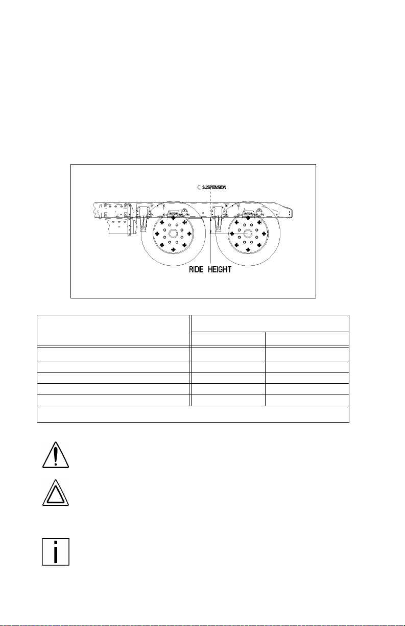
PART 7: STARTING & OPERATING THE VEHICLE
Setting Ride Height
Vehicles equipped with rear air suspensions have their ride height
and axle (pinion) angle(s) preset at the factory. These are precision
settings and should not be altered. Incorrectly adjusted ride height
may result in improper interaxle U-joint working angles. This can
result in premature driveline wear and driveline vibration. If your vehicle is equipped with a Peterbilt rear air suspension, and if it bec om es
necessary to reset the r ide height, you may temporarily set it by following the next procedure. Proper ride height measurement and values are shown in the illustration and table below.
Ride Height Measurement (Location for Tandem Axles Shown)
Proprietary Rear Air Suspension
Air Leaf N/A 1 1.70 (297)
Air Trac 1 1.00 (279) 1 1.00 (279)
Low Air Leaf 8.50 (216) 8.50 (216)
Low Low Air Leaf N/A 6.50 (165)
FLEX
Air N/A 8.50 (216)
*These value s are fo r a fully laden vehicle
Ride Height [inches (mm)]*
Single Drive Tandem Drive
Follow this procedure to temporarily set ride height.
WARNING! To prevent possible injury and damage to
property, ensure that a vehicle is parked and the wheels
chocked before beginning this procedure.
CAUTION: Completing this procedure will enable you to
safely reach the nearest authorized Peterbilt repair facility to have ride height and pinion angle reset using the
proper equipment and technique. Do this as soon as
possible to avoid potential driveline damage.
NOTE: Suitable wheel chocks are at a minimum an 18-inch
(46 cm) long 4x4.
1. Ensure that the air supply and delivery plumbing of the height control valve is consistent with the illustration on the next page.
PB1328 —90— 22-02011 (R02/02)
Page 93

PART 7: STARTING & OPERATING THE VEHICLE
ALIGNMENT PIN OR DOWEL
SUPPLY FROM FORWARD
AIR TANK
EXHAUST
CONTROL ARM
FROM DUMP VALVE SWITCH
FORWARD
DELIVERY TO RH AIR BAG(S)
MOUNTING NUTS
DELIVERY TO LH AIR BAG(S)
LINK BOLT
AIR BAG LINK ROD
02941
Typical Height Control Valve (Top & Rear V iews Looking Forward)
PB1328 —91— 22-02011 (R02/02)
Page 94

PART 7: STARTING & OPERATING THE VEHICLE
CAUTION:
•
The rear of a vehicle will drop about 3 1/2 inches (88
mm) when the air s prings are deflated. Ensu re that no
persons or objects that coul d be injured or dama g e d
are under the vehicle before deflating the air springs.
•
To minimiz e risk of damag e or in ju ry, do not use a
dump valve to deflate the air springs. Rotate the
height control valve(s) manually to ensure positive
control of air spring deflation.
•
To minimize risk of injury, keep away from air springs
as they are being inflated.
NOTE: On dual-valve systems, begin with the LH valve on
the next step.
2. Loosen the fasteners mounting a hei ght control valve to its bracket.
NOTE: At least one of the mounting holes in the height control valve bracket will be slotted to permit rotating the valve.
3. Rotate the valve ei ther clockwise or countercl ockwise until air pressure in the air springs provides the ride height specifi ed f or that
suspension. Measure the ride height from the bottom of the frame
rail to the approxim ate cen terli ne of the rearmost drive ax le hub:
• For tandem axles, make the vertical measurement at the center-
line of the suspension (see illustration on page 91).
• For a single axle, make t he measurement in front of the axle, in the
area forward of the tires but not past the suspension bracket.
4. When at the correct ride height, ensure that the height control
valve lev er is in the neutral position, then install either the built-in
alignment pin or a 1/8-inch (3 mm) dowel (see page 91).
5. Torque the mounting fasteners to 55 — 75 Lb. in. (6.2 — 8.5 N.m.).
6. Remove the alignment pin or dowel.
7. Repeat Steps 2 through 6 above for the RH valve on vehicles with
a dual-valve system.
PB1328 —92— 22-02011 (R02/02)
Page 95

PART 7: STARTING & OPERATING THE VEHICLE
Driving With Deflated Air Springs
If an air spring is ruptured, there will be enough air pressure to drive
the vehicle to a safe stop off the highway to investigate the problem.
WARNING! Your brakes could fail if you continue driving with deflated air springs. Air escaping from the system will lower the air pressure, which could cause a
spring brake to engage. The spring brake may cause
your brakes to drag and burn up the linings. Don’t continue to operate in this condition.
You can get to a repair facility if you do the following:
• Remove the height control link connected to the axle and to the
suspension air valve control arm. This will cause the air valve control arm to center in the closed position.
• The air system can then be pumped up to normal pressure for
continued operation.
WARNING! Low air pressure could make the brakes
unsafe f or driv ing. Before drivin g th e vehi c le, make
sure the pressure does pump up to over 100 psi for normal brake operation. If the air pressure does not pump
up to at least 100 psi, don’t try to move the vehicle.
CAUTION: Operating a vehicle with air suspension bags
either overinflated or underinflated may cause damage
to driveline components. If a vehicle must be operated
under such conditions, do not exceed 5 mph.
PB1328 —93— 22-02011 (R02/02)
Page 96

PART 7: STARTING & OPERATING THE VEHICLE
Driving Tips And Techniques
This section covers additional driving tips and techniques on h ow to
drive your Peterbilt more efficiently. For further information, read the
American Trucking Association’s (ATA)
will give you more tips on starting, shifting, and driving your vehicle.
Coasting
Truck Driver’s Handbook
WARNING! Do not coast with the transmission in neu-
tral or with the clutch pedal depressed—it is a dangerous practice. Without the use of the retarding power of
the drivetrain, your vehicle can reach dangerous
speeds. At very high speeds you may not be able to put
the transmission in any gear. At high speeds you could
seriously damage your vehicle or cause an accident
when you put the transmission in gear. The engine
speed could exceed the maximum governed speed and
cause a serious accident due to mechanical failures.
Do not coast with the transmission in neutral or with the clutch pedal
depressed. Besides being illegal and dangerous, coasting is also
expensive. It causes premature failure or damage to the c lutch and
transmission and overloads the brake system.
Coasting with the transmission in n eutral also prevents proper transm ission component lubrication. During coasting the transmission is driven by
the rear wheels, and the countershaft g ear (which lubricates the tr ansmission components by oil splash) will only be turning at idle speed.
Descending a Grade
. It
WARNING! Do not hold the brake pedal down too long or
too often while going down a steep or long grade. This
could cause the brakes to overheat and reduce their effectiveness. As a result, the vehicle will not slow down at the
usual rate. To reduce the risk of personal injury and/or an
accident, before going down a steep or long grade, reduce
speed and shift the transmission into a lower gear to help
control your vehic le speed. F ailure to f ollow procedures f or
proper downhill operation could result in loss of vehicle
control.
PB1328 —94— 22-02011 (R02/02)
Page 97

PART 7: STARTING & OPERATING THE VEHICLE
Engine Overspeed
CAUTION: To avoid engine damage, do not let the engine
rpm go beyond the maximum governed rpm—valve damage could result if overspeed conditions occur.
NOTE: Often these recommendations are secondary to maintaining an adequate and safe speed relative to the surrounding
traffic and road conditions.
• Operate the engine within the optimum engine rpm range and do
not allow the rpm’s to exceed the maximum governed speed. See
Engine Operation and Maintenance manual
your
regarding engine rpm. When the engine is used as a brake to control vehicle speed (e.g., while driving down a grade), do not allow
the engine rpm to exceed maximum governed speed.
• Under normal load and road conditions operate the engine in the
lower end of the range.
Use of Tachometer
The tachometer is an instrument that aids in obtaining the best performance of the engine and manual transmission, se rving as a guide for
shifting gears. Refer to the
for optimum engine rpm.
ual
If the engine rpm moves beyond the maximum governed speed, indicating an overspeed condition, ap ply the service brake or shi ft to a
higher gear to bring engine rpm within the optimum speed range.
Engine Operation and M aintenance m an-
• When driving downhill: shift to a lower gear, use the engine brake
(if so equipped), and use the service brake, keeping the engine
speed below 2,100 rpm.
When the engine speed reaches its maximum governed speed, the
injection pump governor cuts off fuel to the engine. However, the governor has no control over the engine r pm when it is being driven by
the vehicle’s transmission, for example, on steep downgrades. Apply
service brakes or shift to a higher gear.
Fuel economy and engine performance is also directly related to driving habits:
• The best results in trip time and fuel economy are obtained while
driving the vehicle at a steady speed.
• Shift into higher or lower gears (or apply the service brake) to keep
engine rpm near the lower end of the optimum operating range.
• Avoid rapid acceleration and braking.
for information
PB1328 —95— 22-02011 (R02/02)
Page 98

PART 7: STARTING & OPERATING THE VEHICLE
Warning Alarms
A warning alarm occurs when some condition in the vehicle requires
attention. A warning alarm cannot be turned off or manually reset.
Once triggered, an alarm wi ll continue to exist until the unacceptable
condition or fault in a function is corrected. Warning alarms can be
generated by two main sources in a Model 387: the multiplex instrumentation system and (if equipped) the digital message center.
Multiplex Instrumentat ion System Alarms
NOTE: In addition to the warning messages mentioned in
this part - if any of the following conditions occur after startup
and self-test, the multiplex instrumentation system should be
serviced:
•The speedometer-message center (SMC) pointer exhibits
windshield wiper-like motion and the display reads
NO DATA.
•One or more gauge pointers exhibit wiper-like motion.
•A gauge pointer stays at zero with its red light flashing.
•A gauge pointer goes to and remains at a 2:00 position with
its red light on steady .
A multiplex instrumentation system alar m can be signalled by up to
four indicators:
• A warning message will appear on the SMC display (all alarms).
• The light-emitting diode (LED) warning light in the function’s gauge
will go on (all alarms except ABS and multiplex instrumentation
system faults).
• An audible alarm will sound.
• A light bar icon will light.
NOTE:
•
Warning messages from system alar ms with an audible
alarm can be temporarily overridden by pressing the Reset
switch. You can then press the Select switch to scroll
through other functions - but the message will reappear in
60 seconds. The audible alarm will always be on.
•Warning messages from system alarms without an audible
alarm can be dismissed by pressing the Reset switch. To
view dismissed active messages, turn the ignition off and
back on.
An alarm’s warning message on the SMC will pr eem pt all other SMC
displays until the condition that is causing the alarm is corrected. This
preemption includes other warning messages from earlier alarms and some of these alarms may not have other indicators. Therefore, it
PB1328 —96— 22-02011 (R02/02)
Page 99

PART 7: STARTING & OPERATING THE VEHICLE
is very impor tant that you check the SMC to be aware of all alarm
conditions that may exist in your vehicle’s systems - especially during
the start-up proc edure. A summar y of alar ms and indicators is at th e
end of this part. Follow this procedure to check all SMC warning messages.
1. Observe the first message displayed after the SMC comes on.
• If the odometer is displayed, continue with the start-up procedure.
• If a warning message is displayed instead of the odometer, it is
being generated by the multiplex instrumentation system:
-Look in the summary on page 98 to identify the alarm (gauge).
-Go to the description of that gauge in PART 4: CONTRO LS A ND
DISPLAYS and take the actions indicated to correct the condi-
tion.
2. Continue to check and act on all warning messages until the
odometer is displayed.
Digital Message Center Alarms (Faults)
If so equipped, the digital message center (DMC) in a vehicle will
detect preselected faults during operations. When a new fault is
detected, a LED next to the DIAG key on the DMC’s keypad will illuminate. All faults are either active or inactive (active faults are conditions
that still exist within the vehicle).
• Active faults cannot be erased until they become inactive. They
should be investigated as soon as possible.
• Inactive faults can be erased by using the CANCEL key on the
DMC.
Refer to the DMC operator’s manual that came with your vehicle for
more information.
PB1328 —97— 22-02011 (R02/02)
Page 100

PART 7: STARTING & OPERATING THE VEHICLE
Multiplex Instrumentation System Alarm Summary
Display
H2O TMP Coolant temp. is high
IM CAL System Fault None n o None
IM CFG System Fault None n o None
IM DI AG System Fault None no None
IM LIN System Fault None no None
IM SL FT System Fault None no None
LOW AIR1
LOW AIR2
LO WATER Coolant level is low
NO DATA System Fault None no None
ODO ERR System Fault None no None
OIL TMP
OIL PRES
SMC MEM System Fault N one no None
TRANTMP
Activation
Condition
Low ai r pressure in
air tank #1
Low ai r pressure in
air tank #2
Engine oil temperature is high
Engine oil pres sure i s
low
Main transmission oil
temper ature is high
Gauge LED Buzz
Engine Water
Temperature
Primary air
pressure
Secondary air
pressure
Engine Water
Level
Engine Oil
Temperature
Engine Oil
Pressure
Main Transmission
Oil Tempera ture
Deactivation
Display
yes H2OT OK
yes AIR1 OK
yes AIR2 OK
yes WATER OK
yes OILT OK
yes OIL OK
yes TRAN OK
PB1328 —98— 22-02011 (R02/02)
 Loading...