


1104D

SEBU8172-02
July 20 12
Operation and
Maintenance
Manual
1104D Industrial Engine
NH
(Engine)
NJ (Engine)
Important Safety Information
Most accidents that involve product operation, maintenance and repair are caused by failure to
observe basic safety rules or precautions. An accident can often be avoided by recognizing potentially
hazardous situations before an accident occurs. A person must be alert to potential hazards. This
person should also have the necessary training, skills and tools to perform these functions properly.
Improper operation, lubrication, maintenance or repair of this product can be dangerous and
could result in injury or death.
Do not operate or perform any lubrication, maintenance or repair on this product, until you have
read and understood the operation, lubrication, maintenance and repair information.
Safety precautions and warnings are provided in this manual and on the product. If these hazard
warnings are not heeded, bodily injury or death could occur to you or to other persons.
The hazards are identified by the “Safety Alert Symbol” and followed by a “Signal Word” such as
“DANGER”, “WARNING” or “CAUTION”. The Safety Alert “WARNING” label is shown below.
The meaning of this safety alert symbol is as follows:
Attention! Become Alert! Your Safety is Involved.
The message that appears under the warning explains the hazard and can be either written or
pictorially presented.
Operations that may cause product damage are identified by “NOTICE” labels on the product and in
this publication.
Perkins cannot anticipate every possible circumstance that might involve a potential hazard. The
warnings in this publication and on the product are, therefore, not all inclusive. If a tool, procedure,
work method or operating technique that is not specifically recommended by Perkins is used,
you must satisfy yourself that it is safe for you and for others. You should also ensure that the
product will not be damaged or be made unsafe by the operation, lubrication, maintenance or
repair procedures that you choose.
The information, specifications, and illustrations in this publication are on the basis of information that
was available at the time that the publication was written. The specifications, torques, pressures,
measurements, adjustments, illustrations, and other items can change at any time. These changes can
affect the service that is given to the product. Obtain the complete and most current information before
you start any job. Perkins dealers or Perkins distributors have the most current information available.
When replacement parts are required for this
product Perkins recommends using Perkins
replacement parts.
Failure to heed this warning can lead to prema-
ture failures, product damage, personal injury or
death.

SEBU8172-02 3
Table of Contents
Table of Contents
Foreword ................................................................. 4
Safety Section
Safety Messages .................................................... 6
General Hazard Information ................................... 9
Burn Prevention .................................................... 10
Fire Prevention and Explosion Prevention ............. 11
Crushing Prevention and Cutting Prevention ........ 13
Mounting and Dismounting ................................... 13
High Pressure Fuel Lines ..................................... 13
Before Starting Engine .......................................... 15
Engine Starting ..................................................... 15
Engine Stopping ................................................... 16
Electrical System .................................................. 16
Engine Electronics ................................................ 17
Product Information Section
Model Views ......................................................... 18
Product Identification Information ........................ 23
Operation Section
Lifting and Storage ................................................ 25
Gauges and Indicators .......................................... 27
Features and Controls .......................................... 29
Engine Diagnostics ............................................... 36
Engine Starting ..................................................... 40
Engine Operation .................................................. 43
Engine Stopping ................................................... 44
Cold Weather Operation ....................................... 46
Maintenance Section
Refill Capacities .................................................... 50
Maintenance Recommendations .......................... 67
Maintenance In
terval Schedule ............................ 69
Warranty Sect
ion
Warranty Information .......................................... 105
Index Section
Index ................................................................... 106

4 SEBU8172-02
Foreword
Foreword
Literature Information
This manual co
ntains safety, operation instructions,
lubrication and maintenance information. This
manual should be stored in or near the engine area
in a literatu
re holder or literature storage area. Read,
study and keep it with the literature and engine
information.
English is the primary language for all Perkins
publications. The English used facilitates translation
and consist
ency in electronic media delivery.
Some photographs or illustrations in this manual
show detai
ls or attachments that may be different
from your engine. Guards and covers may have
been removed for illustrative purposes. Continuing
improveme
nt and advancement of product design
may have caused changes to your engine which are
not included in this manual. Whenever a question
arises re
garding your engine, or this manual, please
consult with your Perkins dealer for the latest
available information.
Safety
This safety section lists basic safety precautions.
In addition, this section identifies hazardous,
warnin
g situations. Read and understand the basic
precautions listed in the safety section before
operating or performing lubrication, maintenance and
repair
on this product.
Opera
tion
Operating techniques outlined in this manual are
basic
. They assist with developing the skills and
techniques required to operate the engine more
efficiently and economically. Skill and techniques
deve
lop as the operator gains knowledge of the
engine and its capabilities.
The o
peration section is a reference for operators.
Photographs and illustrations guide the operator
through procedures of inspecting, starting, operating
and
stopping the engine. This section also includes a
discussion of electronic diagnostic information.
Maintenance
Th
e maintenance section is a guide to engine care.
The illustrated, step-by-step instructions are grouped
by fuel consumption, service hours and/or calendar
ti
me maintenance intervals. Items in the maintenance
schedule are referenced to detailed instructions that
follow.
Use fuel consum
ption or service hours to determine
intervals. Calendar intervals shown (daily, annually,
etc.) may be used instead of service meter intervals
if they provid
e more convenient schedules and
approximate the indicated service meter reading.
Recommended
service should be performed at the
appropriate intervals as indicated in the Maintenance
Interval Schedule. The actual operating environment
of the engin
e also governs the Maintenance Interval
Schedule. Therefore, under extremely severe,
dusty, wet or freezing cold operating conditions,
more freque
nt lubrication and maintenance than is
specified in the Maintenance Interval Schedule may
be necessary.
The maintenance schedule items are organized for
a preventive maintenance management program. If
the preven
tive maintenance program is followed, a
periodic tune-up is not required. The implementation
of a preventive maintenance management program
should mi
nimize operating costs through cost
avoidances resulting from reductions in unscheduled
downtime and failures.
Maintenance Intervals
Perform maintenance on items at multiples of the
original requirement. Each level and/or individual
items in
each level should be shifted ahead or back
depending upon your specific maintenance practices,
operation and application. We recommend that
the mai
ntenance schedules be reproduced and
displayed near the engine as a convenient reminder.
We also recommend that a maintenance record be
maint
ained as part of the engine's permanent record.
See the section in the Operation and Maintenance
Manua
l, “Maintenance Records” for information
regarding documents that are generally accepted
as proof of maintenance or repair. Your authorized
Perkins dealer can assist you in adjusting your
maintena
nce s
chedule to meet the needs of your
operating environment.
Overhaul
Major engine overhaul details are not covered in the
Operation and Maintenance Manual except for the
int
erval and the maintenance items in that interval.
Major repairs are best left to trained personnel or
an authorized Perkins dealer. Your Perkins
dea
ler offers a variety of options regarding overhaul
programs. If you experience a major engine failure,
there are also numerous after failure overhaul options
av
ailable from your Perkins de
aler. Consult with
your
dealer for information regarding these options.

SEBU8172-02 5
Foreword
California Proposition 65 Warning
Diesel engine exhaust and some of its constituents
are known to the State of California to cause cancer,
birth defects, and other reproductive harm.
Battery posts, terminals and related accessories
contain lead and lead compounds. Wash hands
after handling.
6 SEBU8172-02
Safety Section
Safety Messages
Safety Section
i02864025
Safety Me ssages
There may be
several specific warning signs on your
engine. The exact location and a description of the
warning signs are reviewed in this section. Please
become fam
iliar with all warning signs.
Ensure that all of the warning signs are legible. Clean
the warnin
g signs or replace the warning signs if
the words cannot be read or if the illustrations are
not visible. Use a cloth, water, and soap to clean
the warni
ng signs. Do not use solvents, gasoline, or
other harsh chemicals. Solvents, gasoline, or harsh
chemicals could loosen the adhesive that secures the
warning
signs. The warning signs that are loosened
could drop off of the engine.
Replace
any warning sign that is damaged or
missing.Ifawarningsignisattachedtoapartofthe
engine that is replaced, install a new warning sign on
the rep
lacement part. Your Perkins dealer or your
distributor can provide new warning signs.
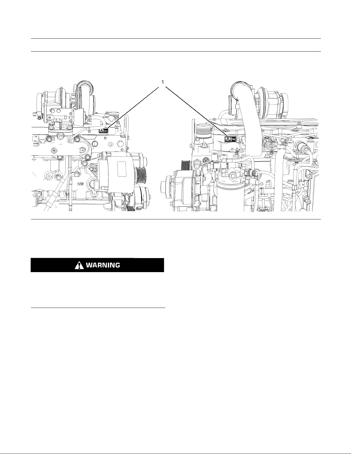
(1) Universal Warning
Do not operate or work on this equipment unless
you h
ave read and understand the instructions
and warnings in the Operation and Maintenance
Manuals. Failure to follow the instructions or
heed
the warnings could result in serious injury
or death.
g01154807
Illustration 1
T
ypical example
The Universal W
arning label (1) is located on both
sides of the valve mechanism cover base. Refer to
illustration 1.
SEBU8172-02 7
Safety Section
Safety Messages
g01268960
Illustration 2
(1) Univ
ersal warning
(2) Han
d (High Pressure)
Contact with high pressure fuel may cause fluid
penetration and burn hazards. High pressure fu-
el spr
ay may cause a fire hazard. Failure to fol-
low these inspection, maintenance and service in-
structions may cause personal injury or death.
8 SEBU8172-02
Safety Section
Safety Messages
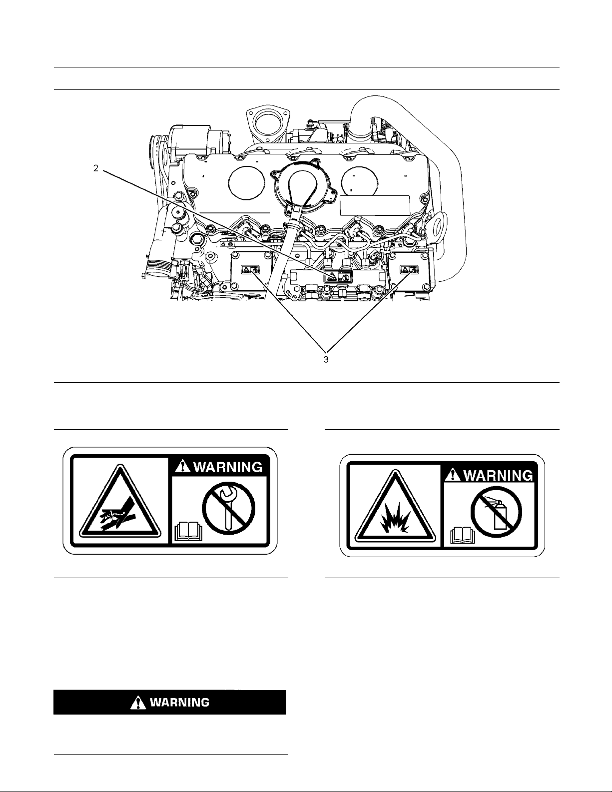
g01426636
Illustration 3
(2) Hand
(High Pressure)
(3) Ethe
r
g01154858
Illustration 4
Typical example
The warning label for the Hand (High Pressure) (2)
is located on the top of the fuel manifold. Refer to
illustration 4.
(3) Ether
Do not use aerosol types of starting aids such as
ether. Such use could result in an explosion and
personal injury.
g01154809
Illustration 5
Typical example
The ether warning label (3) is located on the cover of
the inlet manifold. Refer to illustration 4.
Note: The location of this label will depend on the
application of the engine.
SEBU8172-02 9
Safety Section
General Hazard Information
i02328435
General Hazard Information
g0010454
5
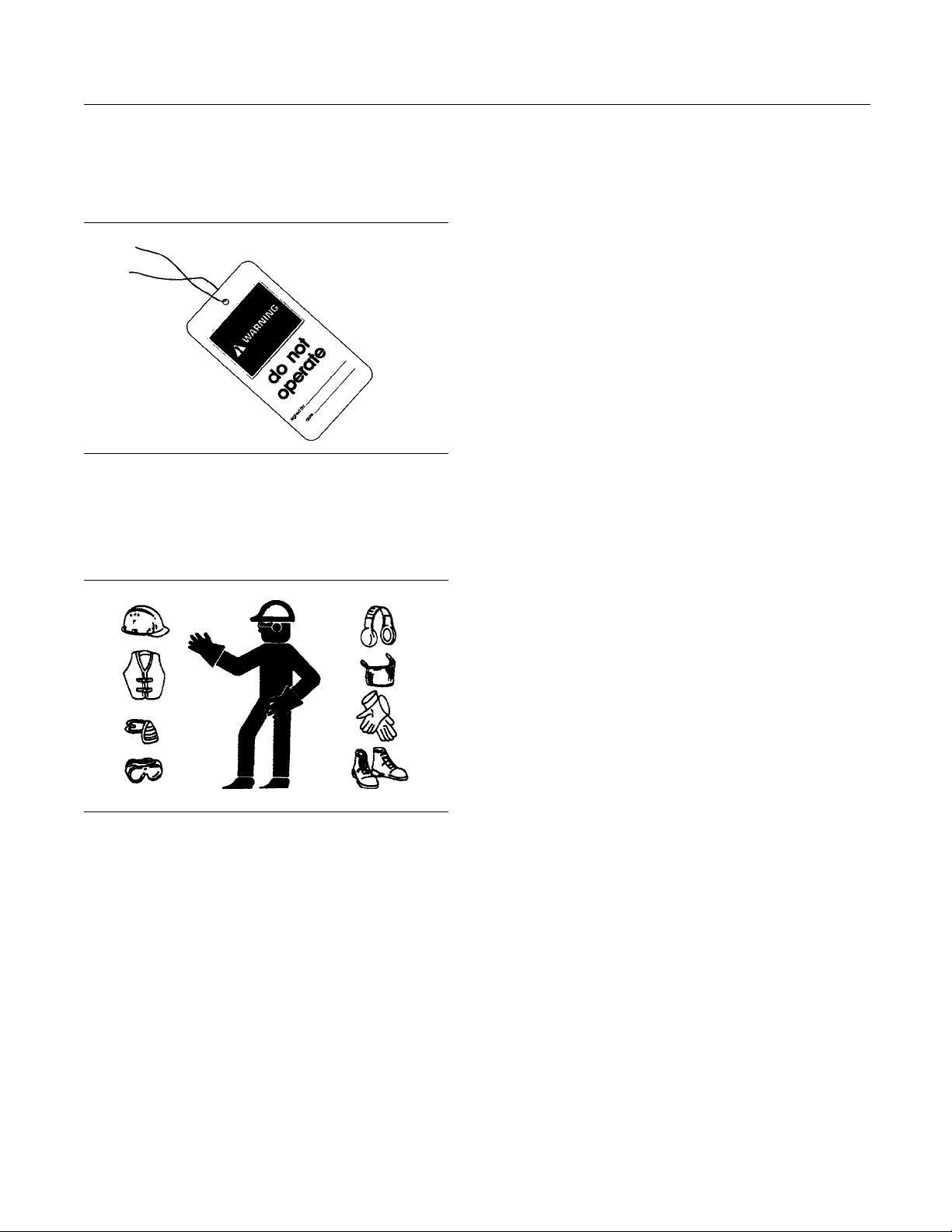
Illustration 6
Attach a “Do Not Operate” warning tag or a similar
warning tag to the start switch or to the controls
before y
ou service the equipment or before you
repair the equipment.
g007
02020
Illustration 7
Wear a hard hat, protective glasses, and other
protective equipment, as required.
Do not wear loose clothing or jewelry that can snag
on controls or on other parts of the engine.
Make sure that all protective guards and all covers
are secured in place on the engine.
Keep the engine free from foreign material. Remove
debris, oil, tools, and other items from the deck, from
wa
lkways, and from steps.
Never put maintenance fluids into glass containers.
D
rain all liquids into a suitable container.
Obey all local regulations for the disposal of liquids.
Use all cleaning solutions with care.
Report all nece
ssary repairs.
Do not allow unauthorized personnel on the
equipment.
Ensure that the power supply is disconnected before
youworkonth
e bus bar or the glow plugs.
Perform maintenance on the engine with the
equipment i
ntheservicingposition.Refertothe
OEM information for the procedure for placing the
equipment in the servicing position.
Pressure Air and Water
Pressurized air and/or water can cause debris
and/or hot water to be blown out. This could result in
personal i
njury.
The direct application of pressurized air or
pressuri
zed water to the body could result in personal
injury.
When pres
surized air and/or water is used for
cleaning, wear protective clothing, protective shoes,
and eye protection. Eye protection includes goggles
or a prot
ective face shield.
The maximum air pressure for cleaning purposes
must be b
elow 205 kPa (30 psi). The maximum
water pressure for cleaning purposes must be below
275 kPa (40 psi).
Fluid Penetration
Pressure can be trapped in the hydraulic circuit long
after the engine has been stopped. The pressure can
cause
hydraulic fluid or items such as pipe plugs to
escape rapidly if the pressure is not relieved correctly.
Do not
remove any hydraulic components or parts
until pressure has been relieved or personal injury
may occur. Do not disassemble any hydraulic
comp
onents or parts until pressure has been relieved
or personal injury may occur. Refer to the OEM
information for any procedures that are required to
reli
eve the hydraulic pressure.
10 SEBU8172-02
Safety Section
Burn Prevention
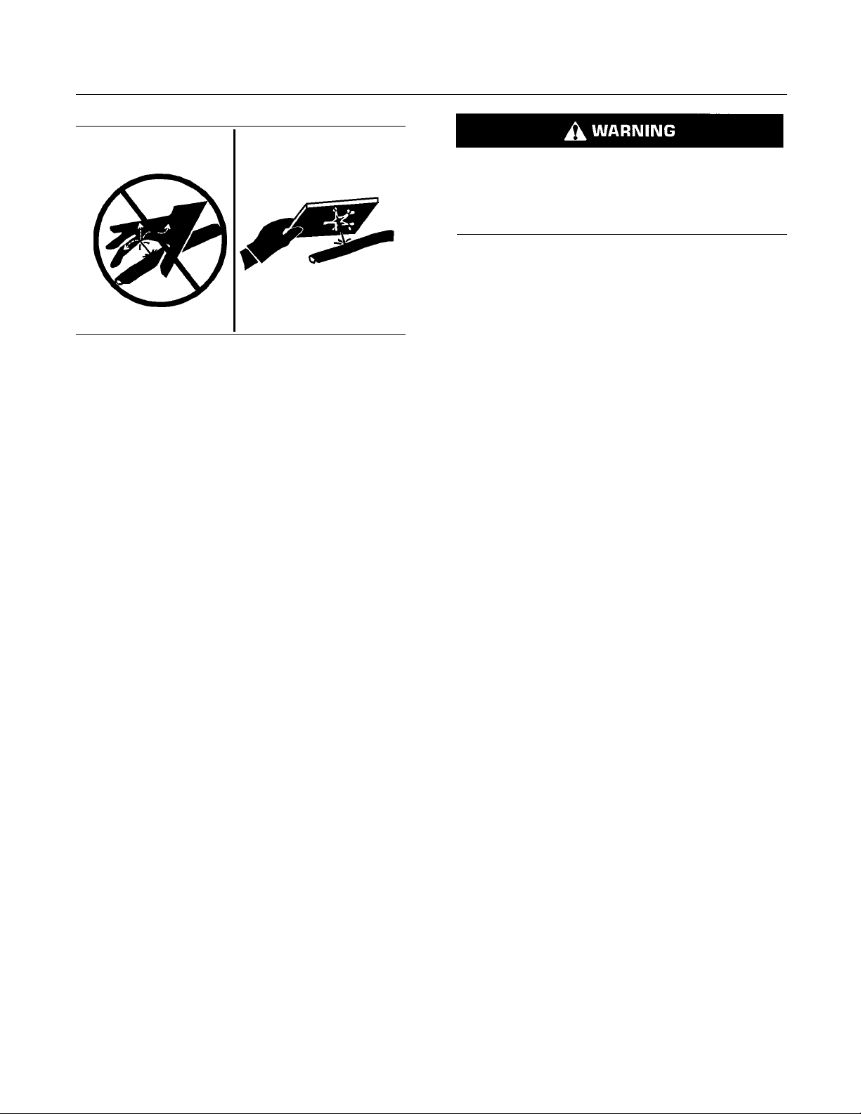
g00687600
Illustration 8
Always use a board or cardboard when you check
for a leak. Leaking fluid that is under pressure can
penetrate body tissue. Fluid penetration can cause
serious injury and possible death. A pin hole leak can
cause severe injury. If fluid is injected into your skin,
you must get treatment immediately. Seek treatment
from a doctor that is familiar with this type of injury.
Containing Fluid Spillage
Care must be taken in order to ensure that fluids
are contained during performance of inspection,
maintenance, testing, adjusting and repair of the
engine. Make provision to collect the fluidwitha
suitable container before any compartment is opened
or before any component is disassembled.
•
Only use the tools that are suitable for collecting
fluids and equipment that is suitable for collecting
fluids.
•
Only use the tools that are suitable for containing
fluids and equipment that is suitable for containing
fluids.
Obey all local regulations for the disposal of liquids.
i02334785
Bur
n P revention
Do not touch any part of an operating engine.
Allow the engine to cool before any maintenance is
pe
rformed on the engine.
Contact with high pressure fuel may cause fluid
penetration and burn hazards. High pressure fu-
el spray may cause a fire hazard. Failure to fol-
low these inspection, maintenance and service in-
structions may cause personal injury or death.
After the engine has stopped, you must wait for 60
seconds in order to allow the fuel pressure to be
purged from the high pressure fuel lines before any
service or repair is performed on the engine fuel lines.
Allow the pressure to be purged in the air system, in
the hydraulic system, in the lubrication system, or in
the cooling system before any lines, fittings or related
items are disconnected.
Coolant
When the engine is at operating temperature, the
engine coolant is hot. The coolant is also under
pressure. The radiator and all lines to the heaters or
to the engine contain hot coolant.
Any contact with hot coolant or with steam can cause
severe burns. Allow cooling system components to
cool before the cooling system is drained.
Check the coolant level after the engine has stopped
and the engine has been allowed to cool.
Ensure that the filler cap is cool before removing the
filler cap. The filler cap must be cool enough to touch
with a bare hand. Remove the filler cap slowly in
order to relieve pressure.
Cooling system conditioner contains alkali. Alkali can
cause personal injury. Do not allow alkali to contact
the skin, the eyes, or the mouth.
Oils
Hot oil and hot lubricating components can cause
personal injury. Do not allow hot oil to contact the
skin. Also, do not allow hot components to contact
the skin.
Batteries
Electrolyte is an acid. Electrolyte can cause personal
injury. Do not allow electrolyte to contact the skin or
the eyes. Always wear protective glasses for servicing
batteries. Wash hands after touching the batteries
and connectors. Use of gloves is recommended.
SEBU8172-02 11
Safety Section
Fire Prevention and Explosion Prevention
i04823662
Fire Prevention and Explosio n
Prevention
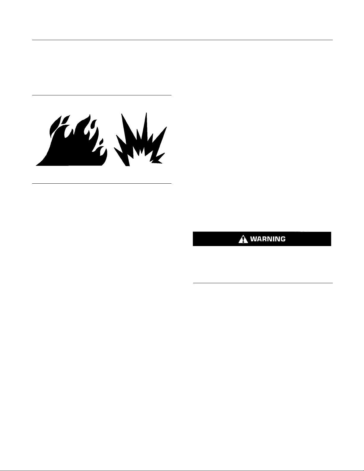
g00704000
Illustra
tion 9
All fuels, most lubricants, and some coolant mixtures
are flamm
able.
Flammable fluids that are leaking or spilled onto hot
surface
s or onto electrical components can cause
a fire. Fire may cause personal injury and property
damage.
After the emergency stop button is operated, ensure
that you allow 15 minutes, before the engine covers
are rem
oved.
Determine whether the engine will be operated in an
envir
onment that allows combustible gases to be
drawn into the air inlet system. These gases could
cause the engine to overspeed. Personal injury,
prop
erty damage, or engine damage could result.
If the application involves the presence of combustible
gase
s, consult your Perkins dealer and/or your
Perkins distributor for additional information about
suitable protection devices.
Remove all flammable combustible materials or
conductive materials such as fuel, oil, and debris from
the
engine. Do not allow any flammable combustible
materials or conductive materials to accumulate on
the engine.
Store fuels and lubricants in correctly marked
containers away from unauthorized persons. Store
oi
ly rags and any flammable materials in protective
containers. Do not smoke in areas that are used for
storing flammable materials.
Do not expose the engine to any flame.
Exhaust shield
s (if equipped) protect hot exhaust
components from oil or fuel spray in a line, a tube,
or a seal failure. Exhaust shields must be installed
correctly.
Do not weld on lines or tanks that contain flammable
fluids. Do not
flame cut lines or tanks that contain
flammable fluid. Clean any such lines or tanks
thoroughly with a nonflammable solvent prior to
welding or fl
ame cutting.
Wiring must be kept in good condition. Ensure that
all electri
cal wires are correctly routed and securely
attached. Check all electrical wires daily. Repair any
wires that are loose or frayed before you operate the
engine. Cl
ean all electrical connections and tighten
all electrical connections.
Eliminate
all wiring that is unattached or unnecessary.
Do not use any wires or cables that are smaller than
the recommended gauge. Do not bypass any fuses
and/or ci
rcuit breakers.
Arcing or sparking could cause a fire. Secure
connecti
ons, recommended wiring, and correctly
maintained battery cables will help to prevent arcing
or sparking.
Contac
t with high pressure fuel may cause fluid
penetration and burn hazards. High pressure fu-
el spray may cause a fire hazard. Failure to fol-
low the
se inspection, maintenance and service in-
structions may cause personal injury or death.
After
the engine has stopped, wait for 60 seconds in
order to allow the fuel pressure to be purged from the
high-pressure fuel lines before any service or repair
is pe
rformed on the engine fuel lines.
Ensure that the engine is stopped. Inspect all lines
and h
oses for wear or for deterioration. Properly
route all hoses. The lines and hoses must have
adequate support and secure clamps.
Properly install oil filters and fuel filters. The filter
housings must be tightened to the correct torque.
Ref
er to the Disassembly and Assembly manual for
more information.
12 SEBU8172-02
Safety Section
Fire Prevention and Explosion Prevention
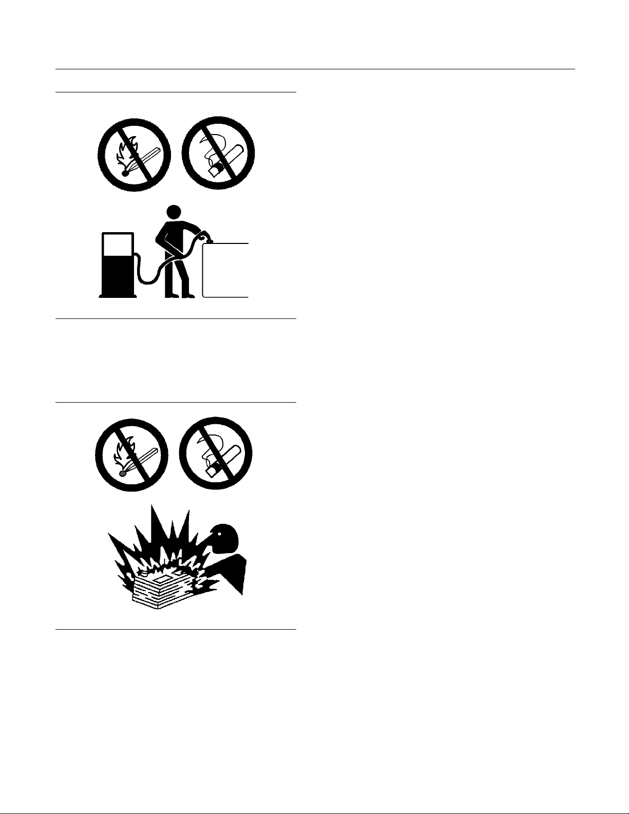
g00704059
Illustration 10
Use caution when you are refueling an engine. Do
not smoke while you are refueling an engine. Do not
refuel an engine near open flames or sparks. Always
stop the engine before refueling.
g02298225
Illustration 11
Gases from a battery can explode. Keep any open
flames or sparks away from the top of a battery. Do
not smoke in battery charging areas.
Never check the battery charge by placing a metal
object across the terminal posts. Use a voltmeter or
ahydrometer.
Incorrect jump
er cable connections can cause
an explosion that can result in injury. Refer to
the Operation Section of this manual for specific
instructions
.
Do not charge a frozen battery.Charging a frozen
battery may c
ause an explosion.
The batteries must be kept clean. The covers
(if equippe
d) must be kept on the cells. Use the
recommended cables, connections, and battery box
covers when the engine is operated.
Fire Extinguisher
Make sure that a fire extinguisher is available. Be
familiar with the operation of the fire extinguisher.
Inspect th
e fire extinguisher and service the fire
extinguisher regularly. Obey the recommendations
on the instruction plate.
Lines, Tubes, and Hoses
Do not bend high-pressure lines. Do not strike
high-pressure lines. Do not install any lines that are
damaged
.
Leaks can cause fires. Consult your Perkins dealer
or your P
erkins distributor for replacement parts.
Replace the parts if any of the following conditions
are pre
sent:
•
High-pressure fuel line or lines are removed.
•
End fittings are damaged or leaking.
•
Outer
coverings are chafed or cut.
•
Wires are exposed.
•
Outer coverings are ballooning.
•
Flex
ible parts of the hoses are kinked.
•
Outer covers have embedded armoring.
•
End fittings are displaced.
Mak
e sure that all clamps, guards, and heat shields
are installed correctly in order to prevent vibration,
rubbing against other parts, and excessive heat.

SEBU8172-02 13
Safety Section
Crushing Prevention and Cutting Prevention
i02143194
Crushing Prevention and
Cutting Preve
ntion
Support the component correctly when work beneath
the component is performed.
Unless other maintenance instructions are provided,
never attempt adjustments while the engine is
running.
Stay clear of all rotating parts and of all moving
parts. Lea
ve the guards in place until maintenance
is performed. After the maintenance is performed,
reinstall the guards.
Keep objects away from moving fan blades. The fan
blades will throw objects or cut objects.
When objects are struck, wear protective glasses in
order to avoid injury to the eyes.
Chips or other debris may fly off objects when objects
are struck. Before objects are struck, ensure that no
one will
be injured by flying debris.
i02235492
Mounting and Dismounting
Inspect the steps, the handholds, and the work area
before mounting the engine. Keep these items clean
and keep these items in good repair.
Mount the engine and dismount the engine only at
locations that have steps and/or handholds. Do not
climb on the engine, and do not jump off the engine.
Face the engine in order to mount the engine or
dismount the engine. Maintain a three-point contact
with the steps and handholds. Use two feet and one
hand or use one foot and two hands. Do not use any
controls as handholds.
Do not stand on components which cannot support
your weight. Use an adequate ladder or use a work
platform. Secure the climbing equipment so that the
equipment will not move.
Do not carry tools or supplies when you mount the
engine or when you dismount the engine. Use a hand
line to raise and lower tools or supplies.
i02861106
High Pressure Fuel Lines
Contact with high pressure fuel may cause fluid
penetration and burn hazards. High pressure fu-
el spray may
cause a fire hazard. Failure to fol-
low these inspection, maintenance and service in-
structions may cause personal injury or death.
14 SEBU8172-02
Safety Section
High Pressure Fuel Lines
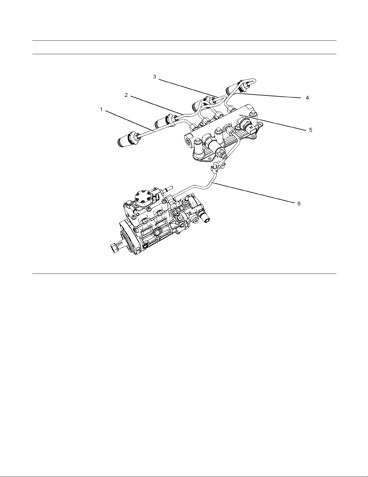
g01425090
Illustration 12
(1)Highpressureline
(2)Highpressureline
(3) High pre ssure line
(4) High pre ssure line
(5) High pressure fuel manifold (rail)
(6) High pressure line
The high pressure fuel lines are the fuel lines that
are between the high pressure fuel pump and the
high pressure fuel manifold and the fuel lines that are
between the fuel manifold and cylinder head. These
fuel lines are different from fuel lines on other fuel
systems.
This is because of the following differences:
•
The high pressure fuel lines are constantly charged
with high pressure.
•
The internal pressures of the high pressure fuel
lines are higher than other types of fuel system.
•
The high pressure fuel lines are formed to shape
and then strengthened by a special process.
Do not step on the high pressure fuel lines. Do not
deflect the high pressure fuel lines. Do not bend or
strike the high pressure fuel lines. Deformation or
damage of the high pressure fuel lines may cause a
point of weakness and potential failure.
Do not check the high pressure fuel lines with the
engine or the starting motor in operation. After the
engine has stopped allow 60 seconds to pass in order
to allow the pressure to be purged before any service
or repair is performed on the engine fuel lines.
Do not loosen the high pressure fuel lines in order
to remove air from the fuel system. This procedure
is not required.
Visually inspect the high pressure fuel lines before
the engine is started. This inspection should be each
day.
If you inspect the engine in operation, always use
the proper inspection procedure in order to avoid
a fluid penetration hazard. Refer to Operation and
Maintenance Manual, “General Hazard Information”.
•
Inspect the high pressure for the following:
damage, deformation, a nick, a cut, a crease, or
adent
SEBU8172-02 15
Safety Section
Before Starting Engine
•
Do not operate t
he engine with a fuel leak. If there
isaleakdonottightentheconnectioninorder
to stop the leak. The connection must only be
tightened to t
he recommended torque. Refer to
Disassembly and Assembly Manual, “Fuel Injection
Lines - Remove and Fuel Injection Lines - Install”.
•
If the high pressure fuel lines are torqued correctly
and the high pressure fuel lines are leaking the
high pressu
re fuel lines must be replaced.
•
Ensure that all clips on the high pressure fuel lines
areinplace
. Do not operate the engine with clips
that are damaged, missing or clips that are loose.
•
Do not atta
ch any other item to the high pressure
fuel lines.
•
Loosened h
igh pressure fuel lines must be
replaced. Also removed high pressure fuel lines
must be replaced. Refer to Disassembly and
Assembly
Manual, “ Fuel Injection Lines - Install”.
i02813489
Before Starting Engine
Before the initial start-up of an engine that is new,
serviced or repaired, make provision to shut the
engine off, in order to stop an overspeed. This may
be accomplished by shutting off the air and/or fuel
supply to the engine.
Overspeed shutdown should occur automatically for
engines that are controlled electronically. If automatic
shutdown does not occur, press the emergency stop
button in order to cut the fuel and/or air to the engine.
Inspect the engine for potential hazards.
Before starting the engine, ensure that no one is on,
underneath, or close to the engine. Ensure that the
area is free of personnel.
If equipped, ensure that the lighting system for the
engine is suitable for the conditions. Ensure that all
lights work correctly, if equipped.
All protective guards and all protective covers must
be installed if the engine must be started in order
to perform service procedures. To help prevent an
accident that is caused by parts in rotation, work
around the parts carefully.
Do not bypass the automatic shutoff circuits. Do not
disable the automatic shutoff circuits. The circuits are
provided in order to help prevent personal injury. The
circuits are also provided in order to help prevent
engine damage.
See the Service
Manual for repairs and for
adjustments.
i02251260
Engine Starting
Do not use aerosol types of starting aids such as
ether. Such use could result in an explosion and
personal injury.
If a warning tag is attached to the engine start switch
or to the controls DO NOT start the engine or move
the controls. Consult with the person that attached
the warning tag before the engine is started.
All protective guards and all protective covers must
be installed if the engine must be started in order
to perform service procedures. To help prevent an
accident that is caused by parts in rotation, work
around the parts carefully.
Start the engine from the operator's compartment or
from the engine start switch.
Always start the engine according to the procedure
that is described in the Operation and Maintenance
Manual, “Engine Starting” topic in the Operation
Section. Knowing the correct procedure will help to
prevent major damage to the engine components.
Knowing the procedure will also help to prevent
personal injury.
To ensure that the jacket water heater (if equipped)
and/or the lube oil heater (if equipped) is working
correctly, check the water temperature gauge
and/or the oil temperature gauge during the heater
operation.
Engine exhaust contains products of combustion
which can be harmful to your health. Always start the
engine and operate the engine in a well ventilated
area. If the engine is started in an enclosed area,
vent the engine exhaust to the outside.
Note: The engine is equipped with a device for cold
starting. If the engine will be operated in very cold
conditions, then an extra cold starting aid may be
required. Normally, the engine will be equipped with
the correct type of starting aid for your region of
operation.
These engines are equipped with a glow plug starting
aid in each individual cylinder that heats the intake
air in order to improve starting.
16 SEBU8172-02
Safety Section
Engine Stopping
i02234873
Engine Stopping
Stop the engin
e according to the procedure in
the Operation and Maintenance Manual, “Engine
Stopping (Operation Section)” in order to avoid
overheating
of the engine and accelerated wear of
the engine components.
Use the Emer
gency Stop Button (if equipped) ONLY
in an emergency situation. Do not use the Emergency
Stop Button for normal engine stopping. After an
emergency
stop, DO NOT start the engine until the
problem that caused the emergency stop has been
corrected.
Stop the engine if an overspeed condition occurs
during the initial start-up of a new engine or an engine
that has b
een overhauled.
To stop an electronically controlled engine, cut the
power to t
he engine and/or shutting off the air supply
to the engine.
i02234878
Electrical System
Never disconnect any charging unit circuit or battery
circuit cable from the battery when the charging unit
is operating. A spark can cause the combustible
gases that are produced by some batteries to ignite.
To help prevent sparks from igniting combustible
gases that are produced by some batteries, the
negative “−” cable should be connected last from the
external power source to the negative “−” terminal
of the starting motor. If the starting motor is not
equipped with a negative “−” terminal, connect the
cable to the engine block.
Check the electrical wires daily for wires that
are loose or frayed. Tighten all loose electrical
connections before the engine is started. Repair all
frayed electrical wires before the engine is started.
See the Operation and Maintenance Manual for
specific starting instructions.
Grounding Practices
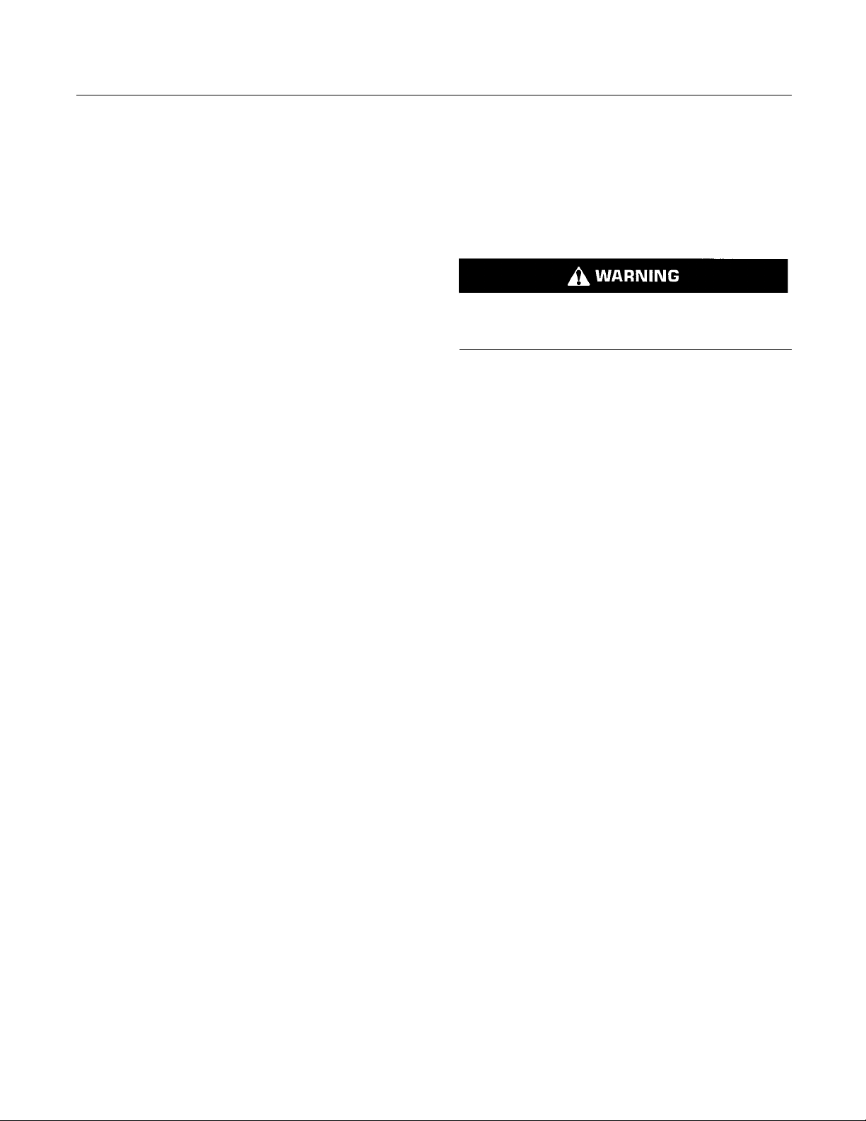
g01162916
Illustration 13
Typical example
(1) Starting motor to engine block
(2) Ground to starting m otor
(3) Ground to battery
g01162918
Illustration 14
Typical example
(4) Ground to engine
(5) Ground to battery
Correct grounding for the engine electrical system
is necessary for optimum engine performance
and reliability. Incorrect grounding will result in
uncontrolled electrical circuit paths and in unreliable
electrical circuit paths.
SEBU8172-02 17
Safety Section
Engine Electronics
Uncontrolled e
lectrical circuit paths can result in
damage to the crankshaft bearing journal surfaces
and to aluminum components.
Engines that are installed without engine-to-frame
ground straps can be damaged by electrical
discharge.
To ensure that the engine and the engine electrical
systems fun
ction correctly, an engine-to-frame
ground strap with a direct path to the battery must be
used. This path may be provided by way of a direct
engine grou
nd to the frame.
The connections for the grounds should be tight and
free of cor
rosion. The engine alternator must be
grounded to the negative “-” battery terminal with
a wire that is adequate to handle the full charging
current of
the alternator.
The power supply connections and the ground
connecti
ons for the engine electronics should always
be from the isolator to the battery.
i02650954
Engine Electronics
Tampe
ring with the electronic system installation
or the OEM wiring installation can be dangerous
and could result in personal injury or death and/or
engin
e damage.
Electrical Shock Hazard. The electronic unit injec-
tors use DC voltage. The ECM sends this voltage
to the electronic unit injectors. Do not come in
contact with the harness connector for the elec-
tronic unit injectors while the engine is operating.
Failure to follow this instruction could result in
personal injury or death.
This engine has a comprehensive, programmable
Engine Monitoring System. The Electronic Control
Module (ECM) has the ability to monitor the engine
operating conditions. If any of the engine parameters
extend outside an allowable range, the ECM will
initiate an immediate action.
The following actions are available for engine
monitoring control:
•
Warning
•
Derate
•
Shutdown
The following monitored engine operating conditions
have the ability to limit engine speed and/or the
engine power
:
•
Engine Coolant Temperature
•
Engine Oil Pressure
•
Engine Spee
d/Timing
•
Intake Manifold Air Temperature
The Engine Monitoring package can vary for different
engine models and different engine applications.
However, t
he monitoring system and the engine
monitoring control will be similar for all engines.
Note: Man
y of the engine control systems and display
modules that are available for Perkins Engines will
work in unison with the Engine Monitoring System.
Together
, the two controls will provide the engine
monitoring function for the specific engine application.
Refer to Troubleshooting for more information on the
Engine M
onitoring System.
18 SEBU8172-02
Product Information Section
Model Views
Product Information
Section
Model Views
i02861104
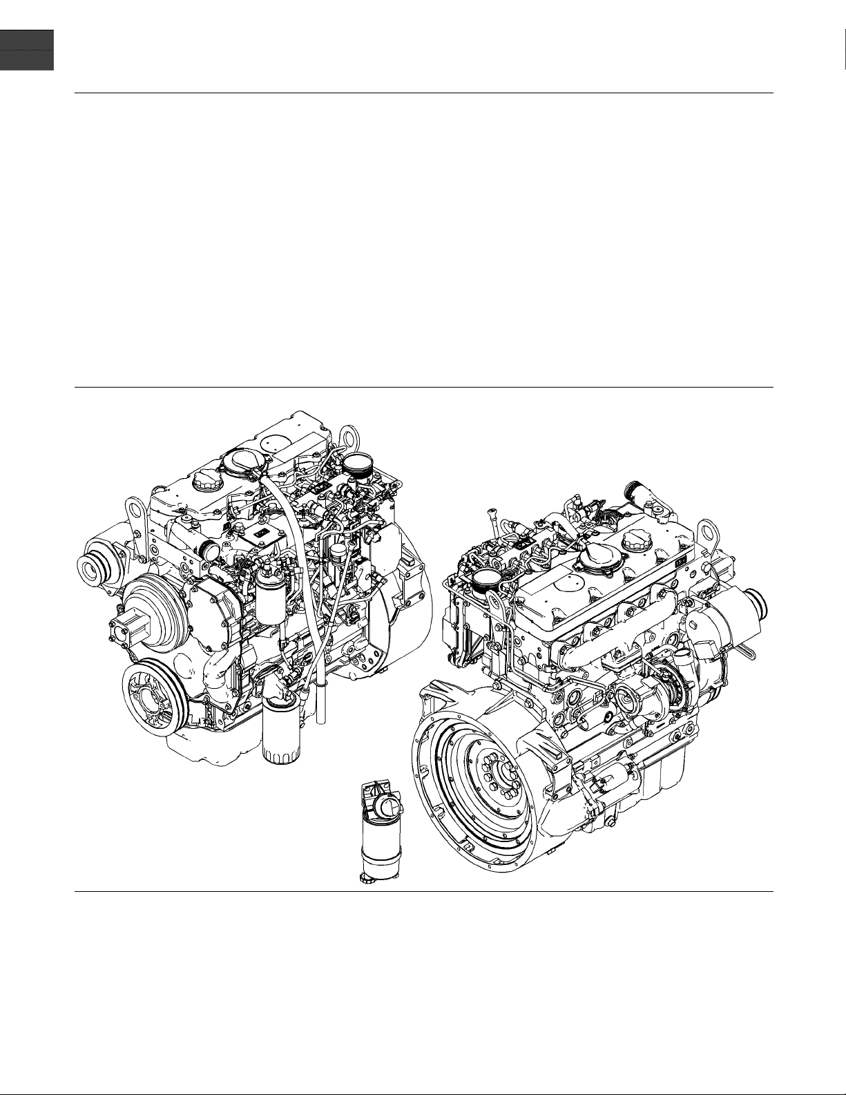
Model View Illustrations
The following model views show typical features
of the engine. Due to individual applications, your
engine may appear different from the illustrations.
g01425089
Illustration 15
The 1104D NJ engine is turbocharged and aftercooled.
SEBU8172-02 19
Product Information Section
Model Views
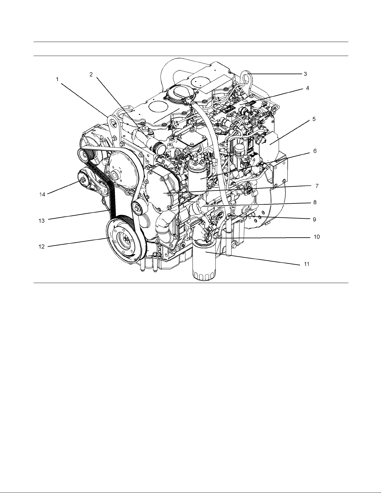
g01428165
Illustration 16
The 1104D NH engine is turbocharged.
Front left engine view
(1) Front lifting eye
(2) Water outlet
(3) Rear lifting eye
(4) Fuel manifold (rail)
(5) Electronic control module
(6) Secondary fuel filter
(7) Water pump
(8) Oil Filler
(9) Oil gauge
(10) Oil sampling valve
(11) Oil filter
(12) Crankshaft pulley
(13) Drive Belt
(14) Belt tensioner
20 SEBU8172-02
Product Information Section
Model Views
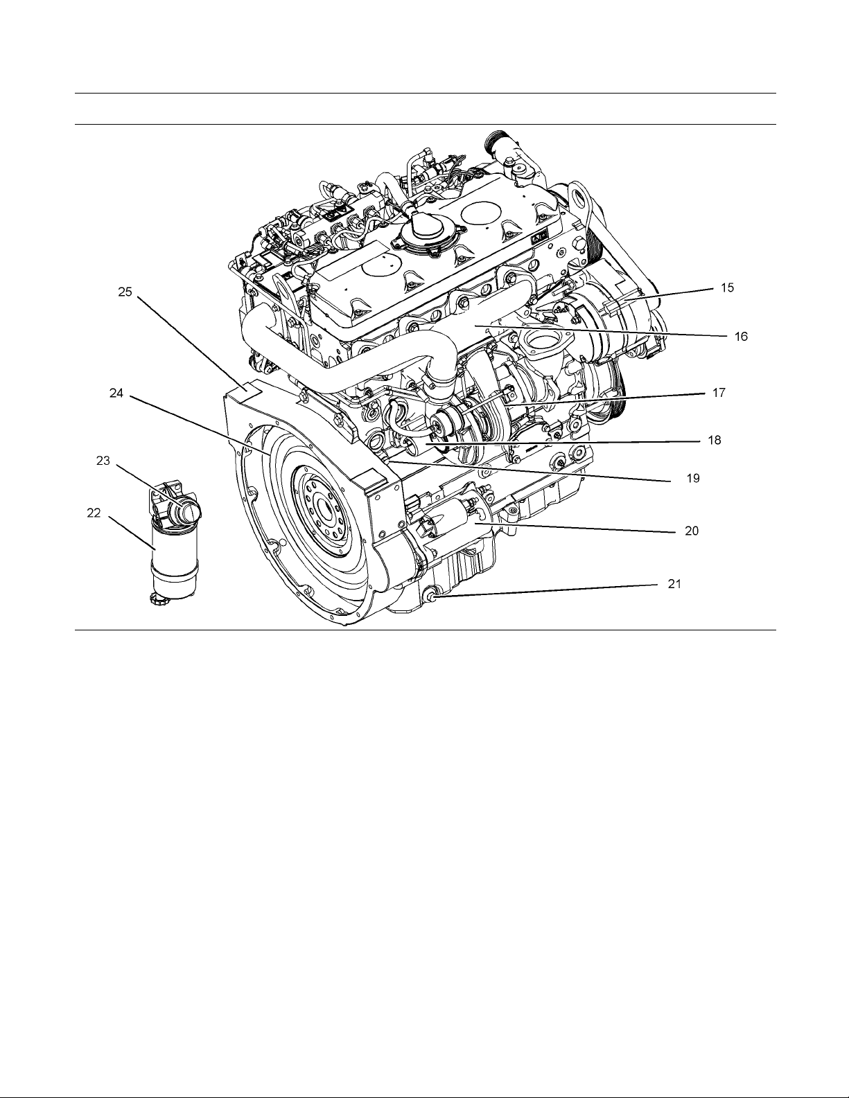
g01428176
Illustration 17
Rear right engine view
(15) Alternator
(16) Exhaust manifold
(17) Turbocharger
(18) Wastegate solenoid
(19) Drain plug or coolant sampling valve
(20) Starting Motor
(21) Oil drain plug
(22) Primary fuel filter
(23) Hand fuel priming pump
(24) Flywheel
(25) Flywheel housing
Note: The primary fuel filter may be mounted off the
engine.
i04925801
Engine Description
The 1104 Electronic Engine models NH and NJ are
designed for the following applications: machine and
industrial mobile equipment. The engine is available
in the following type of aspiration:
•
Turbocharged
•
Turbocharged aftercooled
•
In-line 4 cylinder
Engine Specifications
Note: The front end of the engine is opposite the
flywheel end of the engine. The left and the right
sides of the engine are determined from the flywheel
end. The number 1 cylinder is the front cylinder.
Emissions Control Systems
NH - Direct Diesel Injection, Turbocharger, and
Engine Control Module
NJ - Direct Diesel Injection, Turbocharger with Air to
Air Charge Cooler and Engine Control Module
SEBU8172-02 21
Product Information Section
Model Views
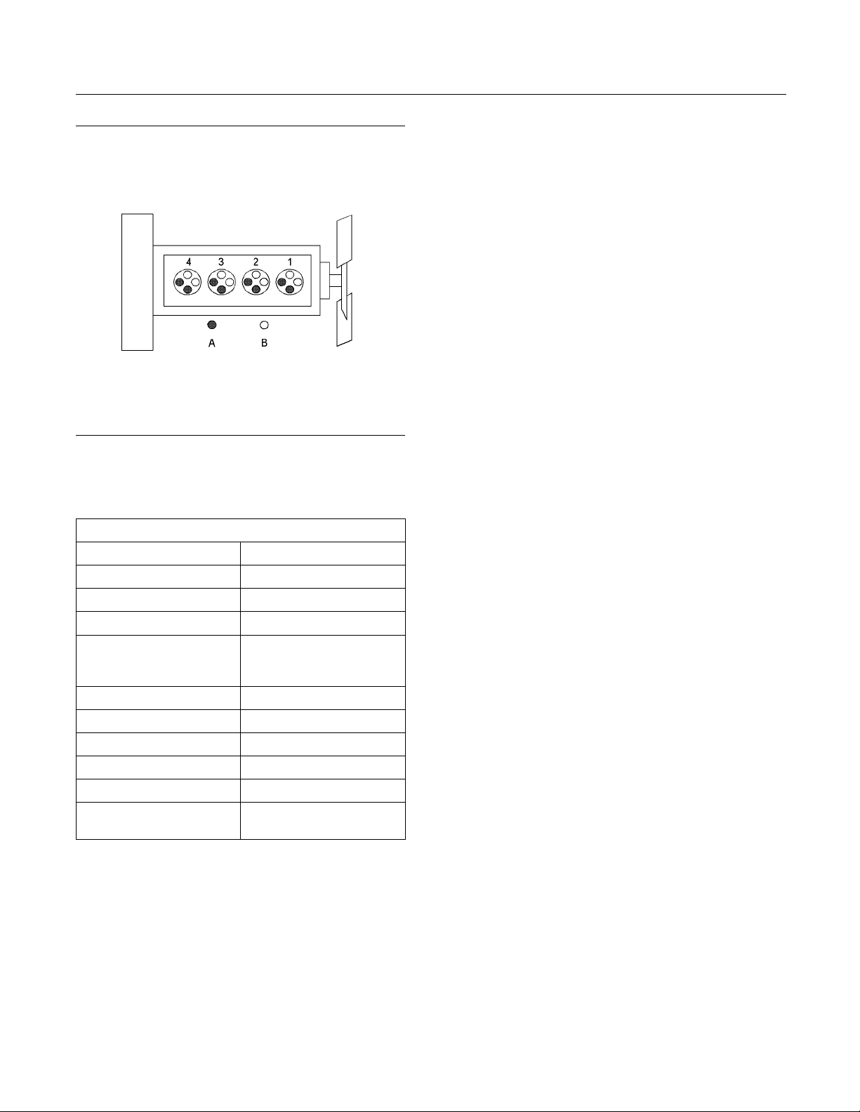
g01187485
Illustration 18
(A) Exhaust valves
(B) Inlet valves
Table 1
1104 Electronic Engine Specifications
Operating Range (rpm)
750 to 2640
(1)
Number of Cylinders
4 In-Line
Bore
105 mm (4.13 inch)
Stroke 127 mm (5.0 inch)
Aspiration NH Turbocharged engine
NJ Turbocharged engine
that is aftercooled
Compression Ratio 16.2:1
Displacement
4.4 L (269 in
3
)
Firing Order 1,3,4,2
Rotation (flywheel end) Counterclockwise
Valve Lash Setting (Inlet) 0.35 mm (0.013 inch)
Va
lve Lash Setting
(Exhaust)
0.35 mm (0.013 inch)
(1)
The operating rpm is dependent on the engine rating, the
application, and the configuration of the throttle.
Electronic Engine Features
The engine operating conditions are monitored.
The Electronic Control Module (ECM) controls the
response of the engine to these conditions and to
the demands of the operator. These conditions and
operator demands determine the precise control of
fuel injection by the ECM. The electronic engine
control system provides the following features:
•
Engine monitoring
•
Engine speed go
verning
•
Control of the injection pressure
•
Cold start strategy
•
Automatic ai
r/fuel ratio co ntrol
•
Torque rise shaping
•
Injection timing control
•
System diag
nostics
For more information on electronic engine features,
refer to th
e Operation and Maintenance Manual,
“Features and Controls” topic (Operation Section).
Engine Diagnostics
The engin
e has built-in diagnostics in order to ensure
that the engine systems are functioning correctly. The
operator will be alerted to the condition by a “Stop or
Warning”
lamp. Under certain conditions, the engine
horsepower and the vehicle speed may be limited.
Theelectronicservicetoolmaybeusedtodisplay
the diag
nostic codes.
There are three types of diagnostic codes: active,
logged,
and event.
Most of the diagnostic codes are logged and stored
in the E
CM. For additional information, refer to
the Operation and Maintenance Manual, “Engine
Diagnostics” topic (Operation Section).
The ECM provides an electronic governor that
controls the injector output in order to maintain the
desir
ed engine rpm.
Engin
e Cooling and Lubrication
The cooling system consists of the following
comp
onents:
•
Gear-driven centrifugal water pump
•
Water temperature regulator which regulates the
engine coolant temperature
•
Gear-driven rotor type oil pump
•
Oil
cooler
The engine lubricating oil is supplied by a rotor type
oi
l pump. The engine lubricating oil is cooled and the
engine lubricating oil is filtered. The bypass valves
can provide unrestricted flow of lubrication oil to
th
e engine if the oil filter element should become
plugged.

22 SEBU8172-02
Product Information Section
Model Views
Engine efficien
cy, efficiency of emission controls, and
engine performance depend on adherence to proper
operation and maintenance recommendations.
Engine perfor
mance and efficiency also depend on
the use of recommended fuels, lubrication oils, and
coolants. Refer to this Operation and Maintenance
Manual, “Mai
ntenance Interval Schedule” for more
information on maintenance items.
SEBU8172-02 23
Product Information Section
Product Identification Information
Product Identification
Information
i02378644
Plate Locations and Film
Locations
g01248563
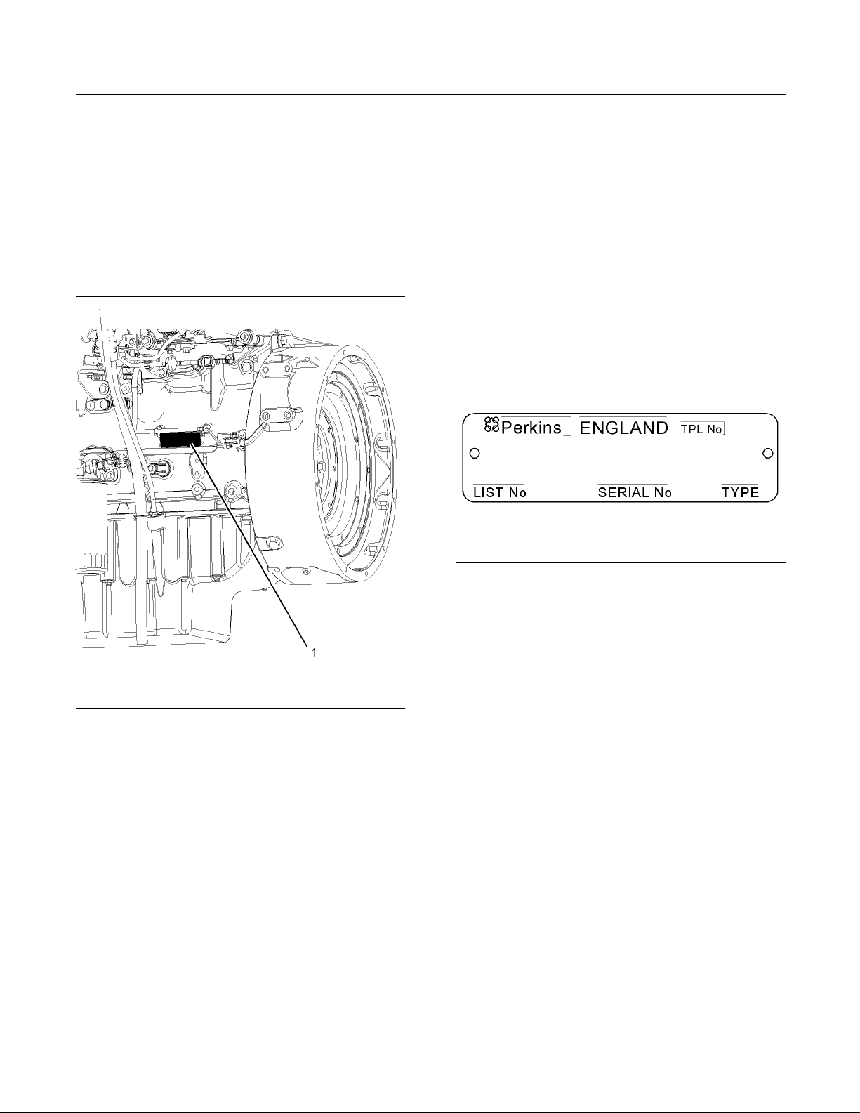
Illustration 19
Location of the serial number plate
Perkins engines are identified by an engine serial
number.
An example of an engine number is
NH*****U000001J.
*****
____________________The list number for the engine
NH
_____________________ _____________ _______Type of engine
U
____________________________Built in the United Kingdom
000001
___________________________Engine Serial Number
J
_____________________________________ Year of Manufacture
Perkins dealer
s or Perkins distributors need all of
these numbers in order to determine the components
that were included with the engine. This permits
accurate iden
tification of replacement part numbers.
The numbers for fuel setting information for electronic
engines are s
tored within the personality module.
These numbers can be read by using the Electronic
Service Tool.
Serial Number Plate (1)
The engine serial number plate is located on the left
side of the cylinder block to the rear of the engine.
g01094203
Illustration 20
Serial number plate
i02164876
Reference N umbers
Information for the following items may be needed to
order parts. Locate the information for your engine.
Record the information in the appropriate space.
Make a copy of this list for a record. Keep the
information for future reference.
Record for Reference
Engine Model _ ______________________________________________
Engine Serial number _____________________________________
Engine Low Idle rpm ______________________________________
Engine Full Load rpm _____________________________________
Primary Fuel Filter _________________________________________
Water Separator Element ________________________________
Secondary Fuel Filter Element __________________________
24 SEBU8172-02
Product Information Section
Product Identification Information
Lubrication Oi
l Filter Element
___________________________
Auxiliary Oil Filter Element _______________________________
Total Lubrication System Capacity _____________________
Total Coolin
g System Capacity
_________________________
Air Cleaner Element _______________________________________
Fan Drive Belt ______________________________________________
Alternator
Belt
______________________________________________
i02861254
Emissions
Certification Film
g01440937
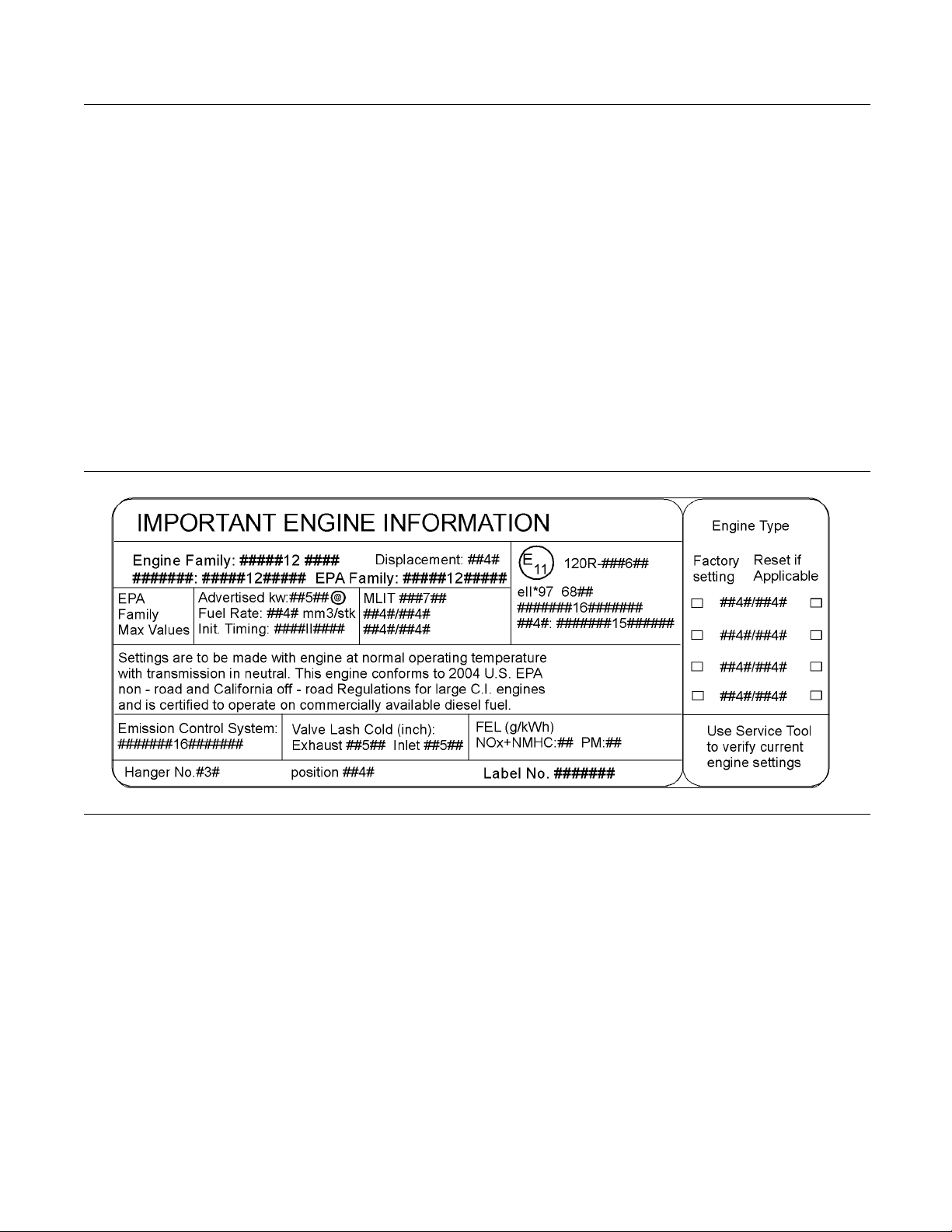
Illustration 21
Typical e xample
SEBU8172-02 25
Operation Section
Lifting and Storage
Operation Section
Lifting and Storage
i02164186
Engine Lifting
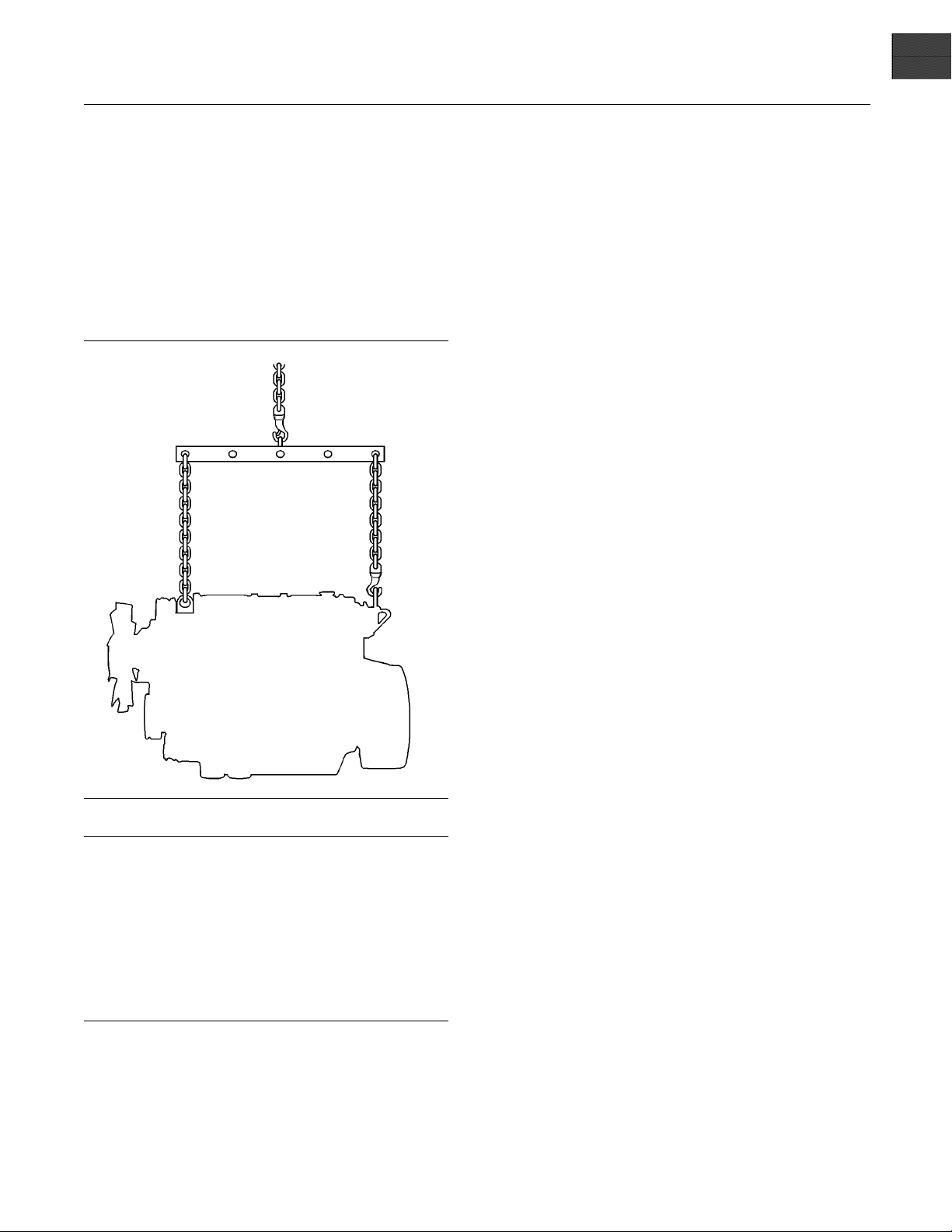
g01097527
Illustration 22
NOTICE
Never bend the eyebolts and the brackets. Only load
the
eyebolts and the brackets under tension. Remem-
ber that the capacity of an eyebolt is less as the angle
between the supporting members and the object be-
com
es less than 90 degrees.
When it is necessary to remove a component at an
an
gle, only use a link bracket that is properly rated for
the weight.
U
se a hoist to remove heavy components. Use
an adjustable lifting beam to lift the engine. All
supporting members (chains and cables) should be
p
arallel to each other. The chains and cables should
be perpendicular to the top of the object that is being
lifted.
Some removals r
equire lifting the fixtures in order to
obtain correct balance and safety.
To re m o ve th e e
ngine ONLY, use the lifting eyes that
are on the engine.
Lifting eyes
are designed and installed for specific
engine arrangements. Alterations to the lifting eyes
and/or the engine make the lifting eyes and the lifting
fixtures obs
olete. If alterations are made, ensure
that correct lifting devices are provided. Consult
your Perkins dealer or your Perkins distributor for
informatio
n regarding fixtures for correct engine
lifting.
i02308881
Engine Storage
If the engine is not started for a month or longer the
lubricating oil will drain from the cylinder walls and
from the piston rings. Rust can form on the cylinder
walls. Rust on the cylinder walls will cause increased
engine wear and a reduction in engine service life.
Perkins are not responsible for damage which may
occur when an engine is in storage after a period in
service.
Your Perkins dealer or your Perkins distributor can
assist in preparing the engine for extended storage
periods.
If an engine is out of operation and if use of the
engine is not planned for more than one month, a
complete protection procedure is recommended.
To help prevent excessive engine wear and corrosion
to the engine, use the following guidelines:
1. Completely clean the outside of the engine.
2. Ensure that the vehicle is on level ground.
3. Drain the fuel system completely and refill
thesystemwithpreservativefuel.1772204
POWERPARTLay-Up1canbemixedwith
the normal fuel in order to change the fuel into
preservative fuel.
If preservative fuel is not available, the fuel system
can be filled with normal fuel. This fuel must be
discarded at the end of the storage period together
with the fuel filter elements.
26 SEBU8172-02
Operation Section
Lifting and Storage
Personal injury can result from hot coolant. Any
contact with hot coolant or with steam c an cause
severe burns. Allow cooling system components
to cool before the cooling system is drained.
4. Drain and refill the cooling system. Refer to this
Operation and Maintenance Manual, “Cooling
System coolant (Commercial Heavy Duty -
Change or Cooling System coolant (ELC) -
Change” for information on draining, flushing and
refilling the cooling system.
Contact with high pressure fuel may cause fluid
penetration and burn hazards. High pressure fu-
el spray may cause a fire hazard. Failure to fol-
low these inspection, maintenance and service in-
structions may cause personal injury or death.
5. Operate the engine until the engine reaches
normal operating temperature. Stop the engine.
After the engine has stopped, you must wait for 60
seconds in order to allow the fuel pressure to be
purged from the high pressure fuel lines before any
service or repair is performed on the engine fuel
lines. If necessary, perform minor adjustments.
Repair any leaks from the low pressure fuel
system and from the cooling, lubrication or air
systems. Replace any high pressure fuel line that
has leaked. Refer to Disassembly and assembly
Manual, “Fuel Injection Lines - Install”.
6. Drain the lubricating oil from the oil pan.
Renew the canister(s) of the lubricating oil filter.
Fill the oil pan to the Full Mark on the engine oil
level gauge with new, clean lubricating oil. Add
1762811 POWERPARTLay-Up2totheoilin
order to protect the engine against corrosion. If
1762811 POWERPART Lay-Up 2 is not available,
use a preservative of the correct specification
instead of the lubricating oil. If a preservative is
used, this must be drained completely at the end
of the storage period and the oil pan must be
refilled to the correct level with normal lubricating
oil.
7. Operate the engine in order to circulate engine oil.
8. Disconnect the battery. Ensure that the battery is
in a fully charged condition. Protect the terminals
against corrosion. 1734115 POWERPART
Lay-Up 3 can be used on the terminals. Put the
battery into safe storage.
9. If equipped, re
place the crankcase breather
element. Seal the end of the breather pipe.
10. Remove the val
ve mechanism cover. Spray
1762811 POWERPART Lay-Up 2 around the
rocker shaft assembly.
11. Remove the glow plugs. Slowly rotate the
crankshaft. By checking the valves, position the
piston at BD
C. Spray 1762811 POWERPART
Lay-Up 2 for two seconds into the cylinder bore.
This procedure must be carried out on each
cylinder.
12. Install the glow plugs. Install the valve mechanism
cover.
13. Remove the pipes that are installed between
the air filt
er assembly and the turbocharger.
Spray 1762811 POWERPART Lay-Up 2 into
the turbocharger. The duration of the spray is
printed o
n the container. Seal the turbocharger
with waterproof tape.
14. Remove th
e exhaust pipe from the output side of
the turbocharger. Spray 1762811 POWERPART
Lay-Up 2 into the turbocharger. The duration of
the spra
y is printed on the container. Seal the
turbocharger with waterproof tape.
15. Seal the
vent of the fuel tank or the fuel filler cap
with waterproof tape.
16. Remove
the alternator drive belt and put the drive
belt into storage.
17. In o rd
er to prevent corrosion to the outside
of the engine, spray the engine with 1734115
POWERPART Lay-Up 3. Do not spray the area
insid
e the alternator.
SEBU8172-02 27
Operation Section
Gauges and Indicators
Gauges and Ind icators
i02861754
Gauges and Indicators
Your engine
may not have the same gauges or all of
the gauges that are described. For more information
about the gauge package, see the OEM information.
Gauges provide indications of engine performance.
Ensure that the gauges are in good working order.
Determine
the normal operating range by observing
the gauges over a period of time.
Noticeab
le changes in gauge readings indicate
potential gauge or engine problems. Problems may
also be indicated by gauge readings that change
even if t
he readings are within specifications.
Determine and correct the cause of any significant
change in the readings. Consult your Perkins dealer
or your P
erkins distributor for assistance.
Some engine applications are equipped with Indicator
Lamps.
Indicator lamps can be used as a diagnostic
aid. There are two lamps. One lamp has an orange
lens and the other lamp has a red lens.
These indicator lamps can be used in two ways:
•
The in
dicatorlampscanbeusedtoidentifythe
current operational status of the engine. The
indicator lamps can also indicate that the engine
has a f
ault. This system is automatically operated
via the ignition switch.
•
The i
ndicator lamps can be used to identify active
diagnostic codes. This system is activated by
pressing the Flash Code button.
Refer to the Troubleshooting Guide, “Indicator
Lamps” for further information.
NOTICE
If no oil pressure is indicated, STOP the engine. If
maximum coolant temperature is exceeded, STOP
the engine. Engine damage can result.
Engine Oil Pressure – Th e oil pressure
should be greatest after a cold engine is
started. The typical engine oil pressure with
SAE10W40is350to450kPa(50to65psi)atrated
rpm.
A lower oil pressure is normal at low idle. If the load
is stable and the gauge reading changes, perform
the following procedure:
1. Remove the load
.
2. Stop the engine.
3. Check and maintain the oil level.
Jacket Water
Coolant Temperature –
Typical temperature range is 83° to 95°C
(181.4° to 171°F). The maximum allowable
temperatur
e at sea level with the pressurized cooling
system at 48 kPa (7 psi) is 103 °C (217.4 °F). Higher
temperatures may occur under certain conditions.
The water te
mperature reading may vary according
to load. The temperature reading should never
exceed 7 °C (44.6 °F) below the boiling point for the
pressuriz
ed system that is being used.
A 100 kPa (14.5 psi) radiator cap may be installed on
the cooling system. The temperature of this cooling
system mus
t not exceed 112 °C (233.6 °F).
If the engine is operating above the normal range
and steam
becomes apparent, perform the following
procedure:
1. Reduce t
he load and the engine rpm.
2. Determine if the engine must be shut down
immedia
tely or if the engine can be cooled by
reducing the load.
3. Inspec
t the cooling system for leaks.
Tachometer – This gauge indicates engine
speed (
rpm). When the throttle control lever
ismovedtothefullthrottlepositionwithout
load, the engine is running at high idle. The engine is
runni
ng at the full load rpm when the throttle control
lever is at the full throttle position with maximum
rated load.
NOTICE
To help prevent engine damage, never exceed the
high idle rpm. Overspeeding can result in serious
damage to the engine. Operation at speeds exceed-
ing high idle rpm should be kept to a minimum.
Ammeter – This gauge indicates the
amount of charge or discharge in the
battery charging circuit. Operation of the
indicator should be to the “+” side of “0” (zero).
Fuel Level – This gauge indicates the fuel
level in the fuel tank. The fuel level gauge
operates when the “START/STOP” switch
is in the “on” position.

28 SEBU8172-02
Operation Section
Gauges and Indicators
Service Hour Meter – The gauge indicates
total operating hours of the engine.
SEBU8172-02 29
Operation Section
Features and Controls
Features and Controls
i02651062
Monitoring System
If the Shutdown mode has been selected and the
warning in
dicator activates, engine shutdown may
take as little as 20 seconds from the time the warn-
ing indicator is activated. Depending on the ap-
plication
, special precautions should be taken to
avoid personal injury. The engine can be restarted
following shutdown for emergency maneuvers, if
necessar
y.
NOTICE
The Engine Monitoring System is not a guarantee
against catastrophic failures. Programmed delays
and derate schedules are designed to minimize false
alarms and provide time for the operator to stop the
engine.
The following parameters are monitored:
•
Coolant temperature
•
Intake air temperature
•
Engine intake manifold pressure
•
Engine Oil pressure
•
Pressure in the fuel rail
•
Engine speed/timing
Programmable O ptions and
Systems Operation
If the Warning/Derate/Shutdown mode has been
selected and the warning indicator activates,
bring the engine to a stop whenever possible. De-
pending on the application, special precautions
should be taken to avoid personal injury.
The engine can be programmed to the following
modes:
“Warning”
The “Warning” lamp and the warning signal (orange
lamp) turn “ON
” and the warning signal is activated
continuously in order to alert the operator that one or
more of the engine parameters is not within normal
operating ra
nge.
“Warning/Derate”
The “Diagnostic” lamp turns “ON” and the warning
signal (red lamp) is activated. After the warning, the
engine powe
r will be derated. The warning lamp will
begin to flash when the derating occurs.
The engine
will be derated if the engine exceeds
preset operational limits. The engine derate is
achieved by restricting the amount of fuel that is
available
for each injection. The amount of this
reduction of fuel is dependent on the severity of the
fault that has caused the engine derate, typically up
to a limit
of 50%. This reduction in fuel results in a
predetermined reduction in engine power.
“Warnin
g/Derate/Shutdown”
The “Diagnostic” lamp turns “ON” and the warning
signal (
red lamp) is activated. After the warning,
the engine power will be derated. The engine will
continue at the rpm of the set derate until a shutdown
of the e
ngine occurs. The engine can be restarted
after a shutdown for use in an emergency.
Ashutd
own of the engine may occur in as little
as 20 seconds. The engine can be restarted after
a shutdown for use in an emergency. However,
the ca
use of the initial shutdown may still exist.
Theenginemayshutdownagaininaslittleas20
seconds.
If there is a signal for low oil pressure or for coolant
temperature, there will be a two second delay in
orde
r to verify the condition.
For each of the programmed modes, refer to
Trou
bleshooting , “Indicator Lamps” for more
information on Indicator Lamps.
For
more information or assistance for repairs, consult
your Perkins dealer or your Perkins distributor.

30 SEBU8172-02
Operation Section
Features and Controls
i02296746
Monitoring System
Table 2
Warning
Lamp
Shutdown
Lamp
Lamp Status Description of lamp status Engine Status
ON ON
Lamp check When the engine start switch is turned to the
“ON” position both lamps will illuminate for 2
seconds only.
The engine has not been
started.
OFF OFF
No faults There are no active diagnostic faults.
Theengineisrunning
normally.
ON OFF
Active
diagnostic
fault
An active diagnostic fault has been detected.
Theengineisrunning
normally.
ON FLASHING
Active
diagnostic
fault
A serious active diagnostic fault has been
detected and an engine derate has been
invoked.
Theengineisrunning
but the engine has been
derated.
FLASHING OFF
Warning One or more of the engine protection values
has been exceeded.
Theengineisrunning
normally.
FLASHING FLASHING
Derate and
warning
One or more of the engine protection values
has been exceeded.
Theengineisrunning
but the engine has been
derated.
ON ON
Engine
shutdown
One or more of the engine protection values has
been exceeded or a serious active diagnostic
fault h
as been detected.
The engine is shutdown or
shutdown is imminent.
i02861773
Sensors and Electrical
Components
Sensor Locations
Ill
ustration 23 shows the typical locations of the
sensors and the ECM on the engine. Specificengines
may appear different from the illustration due to
dif
ferences in applications.
 Loading...