


SEBU8430-00
August 2008
Operation and
Maintenance
Manual
4016-61TRS1 and 4016-61TRS2 Gas
Engines
G16 (Engine)

Important Safety Information
Most accidents that involve product operation, maintenance and repair are caused by failure to observe basic safety rules or precautions. An accident can often be avoided by recognizing potentially hazardous situations before an accident occurs. A person must be alert to potential hazards. This person should also have the necessary training, skills and tools to perform these functions properly.
Improper operation, lubrication, maintenance or repair of this product can be dangerous and could result in injury or death.
Do not operate or perform any lubrication, maintenance or repair on this product, until you have read and understood the operation, lubrication, maintenance and repair information.
Safety precautions and warnings are provided in this manual and on the product. If these hazard warnings are not heeded, bodily injury or death could occur to you or to other persons.
The hazards are identified by the “Safety Alert Symbol” and followed by a “Signal Word” such as “DANGER”, “WARNING” or “CAUTION”. The Safety Alert “WARNING” label is shown below.
The meaning of this safety alert symbol is as follows:
Attention! Become Alert! Your Safety is Involved.
The message that appears under the warning explains the hazard and can be either written or pictorially presented.
Operations that may cause product damage are identified by “NOTICE” labels on the product and in this publication.
Perkins cannot anticipate every possible circumstance that might involve a potential hazard. The warnings in this publication and on the product are, therefore, not all inclusive. If a tool, procedure, work method or operating technique that is not specifically recommended by Perkins is used,
you must satisfy yourself that it is safe for you and for others. You should also ensure that the product will not be damaged or be made unsafe by the operation, lubrication, maintenance or repair procedures that you choose.
The information, specifications, and illustrations in this publication are on the basis of information that was available at the time that the publication was written. The specifications, torques, pressures, measurements, adjustments, illustrations, and other items can change at any time. These changes can affect the service that is given to the product. Obtain the complete and most current information before you start any job. Perkins dealers or Perkins distributors have the most current information available.
When replacement parts are required for this product Perkins recommends using Perkins replacement parts.
Failure to heed this warning can lead to premature failures, product damage, personal injury or death.

SEBU8430 |
3 |
|
Table of Contents |
|
|
Table of Contents |
|
Foreword ................................................................. |
4 |
Safety Section |
|
Safety Messages .................................................... |
5 |
General Hazard Information ................................... |
7 |
Burn Prevention ...................................................... |
9 |
Fire Prevention and Explosion Prevention .............. |
9 |
Crushing Prevention and Cutting Prevention ......... |
11 |
Mounting and Dismounting .................................... |
11 |
Ignition Systems .................................................... |
11 |
Before Starting Engine ........................................... |
11 |
Engine Starting ..................................................... |
12 |
Engine Stopping ................................................... |
12 |
Electrical System .................................................. |
12 |
Product Information Section |
|
Model Views and Specifications ........................... |
14 |
Product Identification Information ........................ |
18 |
Operation Section |
|
Lifting and Storage ................................................ |
20 |
Gauges and Indicators .......................................... |
21 |
Features and Controls .......................................... |
22 |
Engine Starting ..................................................... |
25 |
Engine Operation .................................................. |
28 |
Engine Stopping ................................................... |
29 |
Maintenance Section |
|
Refill Capacities .................................................... |
30 |
Maintenance Interval Schedule ............................ |
36 |
Reference Information Section |
|
Index Section
Index ..................................................................... |
69 |
Reference Materials .............................................. |
65 |
4 |
SEBU8430 |
Foreword |
|
|
|
Foreword
Literature Information
This manual contains safety, operation instructions, lubrication and maintenance information. This manual should be stored in or near the engine area in a literature holder or literature storage area. Read, study and keep it with the literature and engine information.
English is the primary language for all Perkins publications. The English used facilitates translation and consistency.
Some photographs or illustrations in this manual show details or attachments that may be different from your engine. Guards and covers may have been removed for illustrative purposes. Continuing improvement and advancement of product design may have caused changes to your engine which are not included in this manual. Whenever a question arises regarding your engine, or this manual, please consult with your Perkins dealer or your Perkins distributor for the latest available information.
Safety
This safety section lists basic safety precautions. In addition, this section identifies hazardous, warning situations. Read and understand the basic precautions listed in the safety section before
operating or performing lubrication, maintenance and repair on this product.
Operation
Operating techniques outlined in this manual are basic. They assist with developing the skills and techniques required to operate the engine more efficiently and economically. Skill and techniques develop as the operator gains knowledge of the engine and its capabilities.
The operation section is a reference for operators. Photographs and illustrations guide the operator through procedures of inspecting, starting, operating and stopping the engine. This section also includes a discussion of electronic diagnostic information.
Maintenance
The maintenance section is a guide to engine care. The illustrated, step-by-step instructions are grouped by service hours and/or calendar time maintenance intervals. Items in the maintenance schedule are referenced to detailed instructions that follow.
Recommended service should be performed at the appropriate intervals as indicated in the Maintenance Interval Schedule. The actual operating environment of the engine also governs the Maintenance Interval Schedule. Therefore, under extremely severe, dusty, wet or freezing cold operating conditions, more frequent lubrication and maintenance than is specified in the Maintenance Interval Schedule may be necessary.
The maintenance schedule items are organized for a preventive maintenance management program. If the preventive maintenance program is followed, a periodic tune-up is not required. The implementation of a preventive maintenance management program should minimize operating costs through cost avoidances resulting from reductions in unscheduled downtime and failures.
Maintenance Intervals
Perform maintenance on items at multiples of the original requirement. We recommend that the
maintenance schedules be reproduced and displayed near the engine as a convenient reminder. We also recommend that a maintenance record be maintained as part of the engine’s permanent record.
Your authorized Perkins dealer or your Perkins distributor can assist you in adjusting your maintenance schedule to meet the needs of your operating environment.
Overhaul
Major engine overhaul details are not covered in the Operation and Maintenance Manual except for the interval and the maintenance items in that
interval. Major repairs should only be carried out by Perkins authorized personnel. Your Perkins dealer or your Perkins distributor offers a variety of options regarding overhaul programs. If you experience
a major engine failure, there are also numerous after failure overhaul options available. Consult with your Perkins dealer or your Perkins distributor for information regarding these options.
California Proposition 65 Warning
Diesel engine exhaust and some of its constituents are known to the State of California to cause cancer, birth defects, and other reproductive harm. Battery posts, terminals and related accessories contain lead and lead compounds. Wash hands after handling.
SEBU8430 |
5 |
|
Safety Section |
|
Safety Messages |
Safety Section
i02885759
Safety Messages
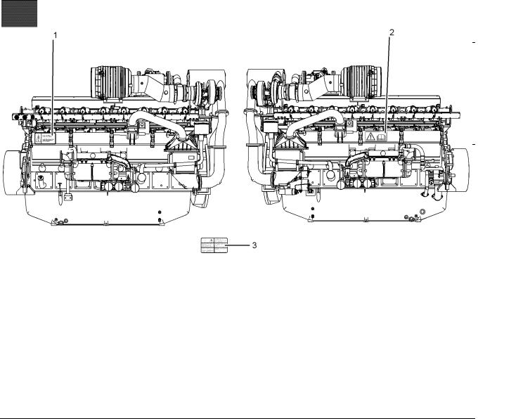
Illustration 1 |
|
Typical example |
|
(1) Engine Oil Level |
(2) Universal warning |
There may be several specific warning signs on your engine. The exact location and a description of the warning signs are reviewed in this section. Please become familiar with all warning signs.
Ensure that all of the warning signs are legible. Clean the warning signs or replace the warning signs if the words cannot be read or if the illustrations are not visible. Use a cloth, water, and soap to clean the warning signs. Do not use solvents, gasoline, or other harsh chemicals. Solvents, gasoline, or harsh chemicals could loosen the adhesive that secures the warning signs. The warning signs that are loosened could drop off of the engine.
Replace any warning sign that is damaged or missing. If a warning sign is attached to a part of the engine that is replaced, install a new warning sign on the replacement part. Your Perkins dealer or your distributor can provide new warning signs.
g01530454
(3) Engine Derate
The safety messages that may be attached on the engine are illustrated .
6 |
SEBU8430 |
Safety Section |
|
Safety Messages |
|
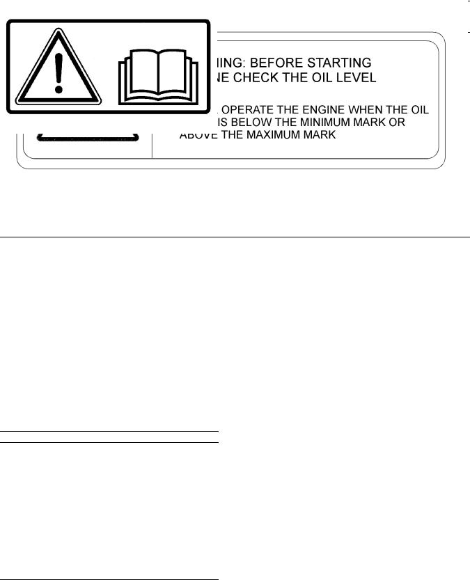
(1) Engine Oil Level
Illustration 2
Typical example
The warning label for checking the engine oil Level
(1) is located on the inlet manifold on the left side of the engine. Refer to illustration 1.
g01241033
The Universal Warning label (2) is located on the inlet manifold on the right side of the engine. Refer to illustration 1.
(2) Universal Warning
Do not operate or work on this equipment unless you have read and understand the instructions and warnings in the Operation and Maintenance Manuals. Failure to follow the instructions or heed the warnings could result in serious injury or death.
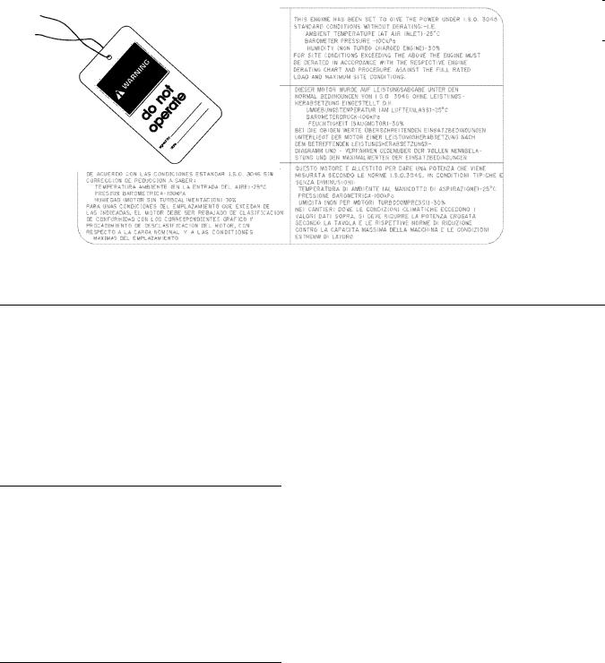
Illustration 3 |
g01234595 |
|
|
Typical example |
|
SEBU8430 |
7 |
|
Safety Section |
|
General Hazard Information |
(3) Engine Derate
Illustration 4 |
g01241021 |
|
|
Typical example |
|
The warning label for derating engine information |
Engine exhaust contains products of combustion |
(3) is located on the control box. Refer to OEM |
which may be harmful to your health. Always start the |
information for the location of the control box. |
engine and operate the engine in a well ventilated |
|
area. If the engine is in an enclosed area, vent the |
i03139708 |
engine exhaust to the outside. |
|
General Hazard Information
Illustration 5 |
g00104545 |
|
Attach a “Do Not Operate” warning tag or a similar warning tag to the start switch or to the controls before the engine is serviced or before the engine is repaired.
Do not allow unauthorized personnel on the engine, or around the engine when the engine is being serviced.
Cautiously remove the following parts. To help prevent spraying or splashing of pressurized fluids, hold a rag over the part that is being removed.
•Filler caps
•Grease fittings
•Pressure taps
•Breathers
•Drain plugs
Use caution when cover plates are removed. Gradually loosen, but do not remove the last two bolts or nuts that are located at opposite ends of the cover plate or the device. Before removing the last two bolts or nuts, pry the cover loose in order to relieve any spring pressure or other pressure.
8 |
SEBU8430 |
Safety Section |
|
General Hazard Information |
|
Pressurized Air and Water
Illustration 6 |
g00702020 |
|
•Wear a hard hat, protective glasses, and other protective equipment, as required.
•When work is performed around an engine that is operating, wear protective devices for ears in order to help prevent damage to hearing.
•Do not wear loose clothing or jewelry that can snag on controls or on other parts of the engine.
•Ensure that all protective guards and all covers are secured in place on the engine.
•Never put maintenance fluids into glass containers. Glass containers can break.
•Use all cleaning solutions with care.
•Report all necessary repairs.
Unless other instructions are provided, perform the maintenance under the following conditions:
•The engine is stopped. Ensure that the engine cannot be started.
•Disconnect the batteries when maintenance is performed or when the electrical system is serviced. Disconnect the battery ground leads. Tape the leads in order to help prevent sparks.
•Do not attempt any repairs that are not understood. Use the proper tools. Replace any equipment that is damaged or repair the equipment.
•If work is carried out on the fuel system obey the local regulations for isolation of the gas supply.
California Proposition 65 Warning
Some constituents of engine exhaust are known to the State of California to cause cancer, birth defects, and other reproductive harm.
Pressurized air and pressurized water can cause debris and/or hot water to be blown out. This could result in personal injury.
When pressurized air and/or pressurized water is used for cleaning, wear protective clothing, protective shoes, and eye protection. Eye protection includes goggles or a protective face shield.
The maximum air pressure for cleaning purposes must be below 205 kPa (30 psi). The maximum water pressure for cleaning purposes must be below 275 kPa (40 psi).
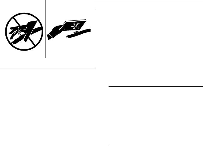
Fluid Penetration
Illustration 7 |
g00687600 |
|
Always use a board or cardboard when you check for a leak. Leaking fluid that is under pressure can penetrate body tissue. Fluid penetration can cause serious injury and possible death. A pin hole leak can cause severe injury. If fluid is injected into your skin, you must get treatment immediately. Seek treatment from a doctor that is familiar with this type of injury.
Containing Fluid Spillage
Care must be taken in order to ensure that fluids are contained during performance of inspection, maintenance, testing, adjusting and repair of the engine. Prepare to collect the fluid with suitable containers before opening any compartment or disassembling any component that contains fluids.
•Tools that are suitable for collecting fluids and equipment that is suitable for collecting fluids
•Tools that are suitable for containing fluids and equipment that is suitable for containing fluids
Obey all local regulations for the disposal of liquids.
SEBU8430 |
9 |
|
Safety Section |
|
Burn Prevention |
|
|
Dispose of Waste Properly |
Oils |
Illustration 8 |
g00706404 |
|
Improperly disposing of waste can threaten the environment. Potentially harmful fluids should be disposed of according to local regulations.
Always use leakproof containers when you drain fluids. Do not pour waste onto the ground, down a drain, or into any source of water.
i03116980
Burn Prevention
Hot oil and hot lubricating components can cause personal injury. Do not allow hot oil or hot components to contact the skin.
If the application has a makeup tank, remove the cap for the makeup tank after the engine has stopped. The filler cap must be cool to the touch.
Batteries
The liquid in a battery is an electrolyte. Electrolyte is an acid that can cause personal injury. Do not allow electrolyte to contact the skin or the eyes.
Do not smoke while checking the battery electrolyte levels. Batteries give off flammable fumes which can explode.
Always wear protective glasses when you work with batteries. Wash hands after touching batteries. The use of gloves is recommended.
i02415237
Fire Prevention and Explosion Prevention
Do not touch any part of an operating engine. Allow the engine to cool before any maintenance is performed on the engine. Relieve all pressure in the appropriate system before any lines, fittings or related items are disconnected.
Coolant
When the engine is at operating temperature, the engine coolant is hot. The coolant is also under pressure. The radiator, the heat exchanger, the heater and lines contain hot coolant. Any contact with hot coolant or with steam can cause severe burns. Allow cooling system components to cool before the cooling system is drained.
Check the coolant level after the engine has stopped and the engine has been allowed to cool. Ensure that the filler cap is cool before removing the filler cap. The filler cap must be cool enough to touch with a bare hand. Remove the filler cap slowly in order to relieve pressure.
Cooling system conditioner is an alkali. Alkali can cause personal injury. Do not allow alkali to contact the skin, the eyes, or the mouth.
Illustration 9 |
g00704000 |
|
All fuels, most lubricants, and some coolant mixtures are flammable.
Flammable fluids that are leaking or spilled onto hot surfaces or onto electrical components can cause a fire. Fire may cause personal injury and property damage.
A flash fire may result if the covers for the engine crankcase are removed within fifteen minutes after an emergency shutdown.
10 |
SEBU8430 |
Safety Section |
|
Fire Prevention and Explosion Prevention |
|
Determine whether the engine will be operated in an environment that allows combustible gases to be drawn into the air inlet system. These gases could cause the engine to overspeed. Personal injury, property damage, or engine damage could result.
If the application involves the presence of combustible gases, consult your Perkins dealer for additional information about suitable protection devices. All local regulations must be observed.
Remove all flammable materials such as fuel, oil, and debris from the engine. Do not allow any flammable materials to accumulate on the engine.
Store fuels and lubricants in properly marked containers away from unauthorized persons. Store oily rags and any flammable materials in protective containers. Do not smoke in areas that are used for storing flammable materials.
Do not expose the engine to any flame.
Exhaust shields (if equipped) protect hot exhaust components from oil or fuel spray in case of a line, a hose, or a seal failure. Exhaust shields must be installed correctly.
Do not weld on lines or tanks that contain flammable fluids. Do not flame cut lines that contain flammable fluid. Clean any such lines thoroughly with a nonflammable solvent prior to welding or flame cutting.
Wiring must be kept in good condition. All electrical wires must be properly routed and securely attached. Check all electrical wires daily. Repair any wires that are loose or frayed before you operate the engine. Clean all electrical connections and tighten all electrical connections.
Eliminate all wiring that is unattached or unnecessary. Do not use any wires or cables that are smaller than the recommended gauge. Do not bypass any fuses and/or circuit breakers.
Arcing or sparking could cause a fire. Secure connections, recommended wiring, and properly maintained battery cables will help to prevent arcing or sparking.
Inspect all lines and hoses for wear or for deterioration. The hoses must be properly routed. The lines and hoses must have adequate support and secure clamps. Tighten all connections to the recommended torque. Leaks can cause fires.
Oil filters and fuel filters must be properly installed. The filter housings must be tightened to the proper torque.
Illustration 10 |
g00704135 |
|
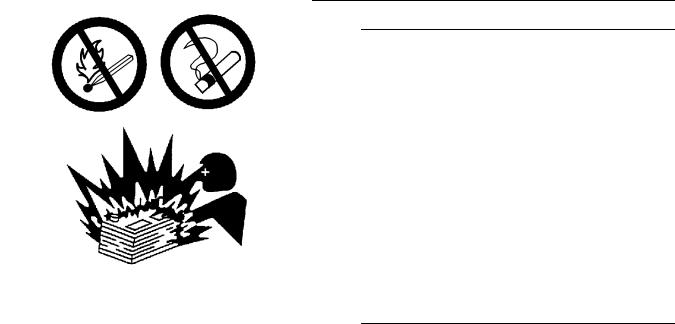
Gases from a battery can explode. Keep any open flames or sparks away from the top of a battery. Do not smoke in battery charging areas.
Never check the battery charge by placing a metal object across the terminal posts. Use a voltmeter or a hydrometer.
Improper jumper cable connections can cause an explosion that can result in injury. Refer to the Operation Section of this manual for specific instructions.
Do not charge a frozen battery. This may cause an explosion.
The batteries must be kept clean. The covers (if equipped) must be kept on the cells. Use the
recommended cables, connections, and battery box covers when the engine is operated.
Fire Extinguisher
Make sure that a fire extinguisher is available. Be familiar with the operation of the fire extinguisher. Inspect the fire extinguisher and service the fire extinguisher regularly. Obey the recommendations on the instruction plate.
Lines, Tubes and Hoses
Do not bend high pressure lines. Do not strike high pressure lines. Do not install any lines that are bent or damaged.
SEBU8430 |
11 |
|
Safety Section |
|
Crushing Prevention and Cutting Prevention |
Repair any lines that are loose or damaged. Leaks can cause fires. Consult your Perkins dealer for repair or for replacement parts.
Check lines, tubes and hoses carefully. Do not use your bare hand to check for leaks. Use a board or cardboard to check for leaks. Tighten all connections to the recommended torque.
Replace the parts if any of the following conditions are present:
•End fittings are damaged or leaking.
•Outer coverings are chafed or cut.
•Wires are exposed.
•Outer coverings are ballooning.
•Flexible part of the hoses are kinked.
•Outer covers have embedded armoring.
•End fittings are displaced.
Make sure that all clamps, guards, and heat shields are installed correctly. During engine operation, this will help to prevent vibration, rubbing against other parts, and excessive heat.
i02143194
i02453744
Mounting and Dismounting
The steps or handholds may not be installed on the engine. Refer to the OEM for information before any maintenance or repair is performed.
Inspect the steps, the handholds, and the work area before mounting the engine. Keep these items clean and keep these items in good repair.
Mount the engine and dismount the engine only at locations that have steps and/or handholds. Do not climb on the engine, and do not jump off the engine.
Face the engine in order to mount the engine or dismount the engine. Maintain a three-point contact with the steps and handholds. Use two feet and one hand or use one foot and two hands. Do not use any controls as handholds.
Do not stand on components which cannot support your weight. Use an adequate ladder or use a work platform. Secure the climbing equipment so that the equipment will not move.
Do not carry tools or supplies when you mount the engine or when you dismount the engine. Use a hand line to raise and lower tools or supplies.
Crushing Prevention and
Cutting Prevention
Support the component correctly when work beneath the component is performed.
Unless other maintenance instructions are provided, never attempt adjustments while the engine is running.
Stay clear of all rotating parts and of all moving parts. Leave the guards in place until maintenance is performed. After the maintenance is performed, reinstall the guards.
Keep objects away from moving fan blades. The fan blades will throw objects or cut objects.
When objects are struck, wear protective glasses in order to avoid injury to the eyes.
Chips or other debris may fly off objects when objects are struck. Before objects are struck, ensure that no one will be injured by flying debris.
i02415253
Ignition Systems
Ignition systems can cause electrical shocks. Avoid contacting the ignition system components and wiring.
i02453806
Before Starting Engine
Inspect the engine for potential hazards.
Before starting the engine, ensure that no one is on, underneath, or close to the engine. Ensure that the area is free of personnel.
Ensure that the engine is equipped with a lighting system that is suitable for the conditions. Ensure that all lights work properly.

12 |
SEBU8430 |
Safety Section |
|
Engine Starting |
|
All protective guards and all protective covers must be installed if the engine must be started in order to perform service procedures. To help prevent an accident that is caused by parts in rotation, work around the parts carefully.
i00659907
Engine Stopping
Do not bypass the automatic shutoff circuits. Do not disable the automatic shutoff circuits. The circuits are provided in order to help prevent personal injury. The circuits are also provided in order to help prevent engine damage.
The initial start-up of a new engine or a engine that has been serviced make provision to shut the engine off, in order to stop an overspeed. This may be accomplished by shutting off the fuel supply to the engine, or shutting off the ignition system.
i03101447
Engine Starting
If a warning tag is attached to the engine start switch or to the controls, DO NOT start the engine or move the controls. Consult with the person that attached the warning tag before the engine is started.
To avoid overheating of the engine and accelerated wear of the engine components, stop the engine according to the instructions in this Operation and Maintenance Manual, “Engine Stopping” topic (Operation Section).
Use the Emergency Stop Button (if equipped) ONLY in an emergency situation. Do not use the Emergency Stop Button for normal engine stopping. After an emergency stop, DO NOT start the engine until the problem that caused the emergency stop has been corrected.
On the initial start-up of a new engine or an engine that has been serviced, make provisions to stop the engine if an overspeed occurs. This may be accomplished by shutting off the fuel supply to the engine, or shutting off the ignition system.
i02436641
Electrical System
All protective guards and all protective covers must be installed if the engine must be started in order to perform service procedures. To help prevent an accident that is caused by parts in rotation, work around the parts carefully.
If there is a possibility that unburned gas remains in the exhaust system, refer to the purge procedure in this Operation and Maintenance Manual, “Engine Starting” topic in the Operation Section.
Always start the engine according to the procedure that is described in the Operation and Maintenance Manual, “Engine Starting” topic in the Operation Section. Knowing the correct procedure will help to prevent major damage to the engine components. Knowing the procedure will also help to prevent personal injury.
To ensure that the jacket water heater (if equipped) is working properly, check the water temperature and the oil temperature during heater operation.
Engine exhaust contains products of combustion which can be harmful to your health. Always start the engine and operate the engine in a well ventilated area. If the engine is started in an enclosed area, vent the engine exhaust to the outside.
Never disconnect any charging unit circuit or battery circuit cable from the battery when the charging unit is operating. A spark can cause the combustible gases that are produced by some batteries to ignite.
To help prevent sparks from igniting combustible gases that are produced by some batteries, the negative “−” cable should be connected last from the external power source to the negative “−” terminal of the starting motor. If the starting motor is not equipped with a negative “−” terminal, connect the cable to the engine block.
Check the electrical wires daily for wires that are loose or frayed. Tighten all loose electrical
connections before the engine is started. Repair all frayed electrical wires before the engine is started. See the Operation and Maintenance Manual for specific starting instructions.
Grounding Practices
Note: All ground lines must return to the battery ground.

SEBU8430
Illustration 11 |
g01217202 |
|
|
Typical example |
|
(1)Starting motor to ground
(2)Battery negative to engine
Correct grounding for the engine electrical system is necessary for optimum engine performance and reliability. Incorrect grounding will result in
uncontrolled electrical circuit paths and in unreliable electrical circuit paths.
Uncontrolled electrical circuit paths can result in damage to the crankshaft bearing journal surfaces and to aluminum components.
The connections for the grounds should be tight and free of corrosion. The engine alternator must be grounded to the negative “-” battery terminal with
a wire that is adequate to handle the full charging current of the alternator.
The power supply connections and the ground connections for the engine electronics should always be from the isolator to the battery.
13 Safety Section Electrical System

14 |
SEBU8430 |
Product Information Section |
|
Model Views and Specifications |
|
Product Information
Section
Model Views and
Specifications
i02885828
Model View Illustrations
The illustrations show various typical features of 4016 Series TRS Engine. The illustrations do not show all of the options that are available.
Illustration 12 |
|
g01525185 |
|
|
|
Typical example |
|
|
(1) Ignition coils |
(4) Engine oil filters |
(7) Oil filler cap |
(2) Air filter |
(5) The inspection cover for the Crankcase |
|
(3) Charge air cooler |
(6) Oil level gauge (dipstick) |
|
SEBU8430 |
15 |
|
Product Information Section |
|
Model Views and Specifications |
|
|
|
|
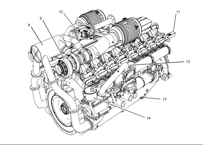
Illustration 13 |
|
g01525189 |
|
|
|
||
Typical example |
|
|
|
(8) |
Tumbulator |
(11) Rail for the engine wiring |
(14) Open breather system |
(9) |
Turbocharger |
(12) Throttle |
|
(10) Gas control valve |
(13) Oil drain plug |
|
|
i02885810
Product Description
The Perkins Engines were developed in order to provide gas engines for generator set applications. The engines have the ability to burn a wide variety of gaseous fuels.
Fuel System
The fuel is delivered to the gas control valve. The gas must be at a constant pressure and the gas pressure must be stable. The pressure must be within a range of 5 to 25 kPa (0.72 to 3.6 psi). Higher pressure will need to be reduced with an additional gas regulator.
The venturi is located in the gas mixer body immediately before the turbocharger. As air is accelerated through the venturi gas is mixed with the air. This mixture is compressed by the turbocharger. The mixture passes through the tumbulator, and the charge coolers, and into the inlet manifolds. The speed and the load is governed by electronically controlled throttle valves.
A digitally controlled gas valve maintains the air/fuel ratio. This system is adjustable. Refer to Systems Operation, Testing and Adjusting for details. This is the only means of adjusting the exhaust emissions.
Ignition System
The engine is equipped with an Electronic Ignition System (EIS). The EIS provides dependable firing and low maintenance. The EIS provides precise control of the following factors:
16 |
SEBU8430 |
Product Information Section |
|
Model Views and Specifications |
|
•Voltage
•Duration of the spark
•Ignition timing
•Level of energy of the ignition
All 4016TRS gas engines are equipped with a device to detect detonation which is connected directly into the ignition system. This device automatically retards the ignition timing.
The ignition timing is retarded when excessive detonation is sensed. If detonation continues after full retardation, then the engine must be shut down.
Lubrication System
The engine lubrication oil is supplied by a pump that is driven by a gear. The oil is cooled and the oil is filtered. A bypass valve provides unrestricted flow of lubrication oil to the engine parts if the oil filter elements become plugged. The bypass valve will open if the oil filter differential pressure reaches 34.4 to 48.2 kPa (5 to 7 psi). The engine oil pressure operates in a range of 415 to 450 kPa (60 to 65 psi).
Note: The engine lubrication oil is not filtered when the bypass valve is open. Do not allow the engine to operate when the bypass valve is open. This can damage the engine components.
The system is used when recovery of heat is not an important factor.
Cogeneration engine
Cogeneration uses energy from heat which would otherwise be wasted.
The following items are not supplied:
•Water pumps
•Water temperature regulator ( thermostat)
•All water tube assemblies
This system is the responsibility of the OEM.
Engine Service Life
Engine efficiency and maximum utilization of engine performance depend on adherence to proper operation and maintenance recommendations. This includes the use of recommended lubricants, fuels, and coolants.
For the engine maintenance that is required, refer to the Operation and Maintenance Manual,
“Maintenance Interval Schedule” in the Maintenance Section.
i02885756
Cooling System
The water enters the engine from the oil cooler and the water is passed through the cylinder block. The water exits the cylinder head into the rail. The water exits the engine from the water outlet.
Electrounit
This type of engine is supplied with the following components:
•Jacket water coolant pump
•Water temperature regulator (thermostat)
•Coolant pipe for the charge cooler
•A water pump for the charge cooler
•A water temperature regulator (thermostat) that controls the water inlet temperature for the charge cooler
•Battery charging alternator
Specifications
General Engine Specifications
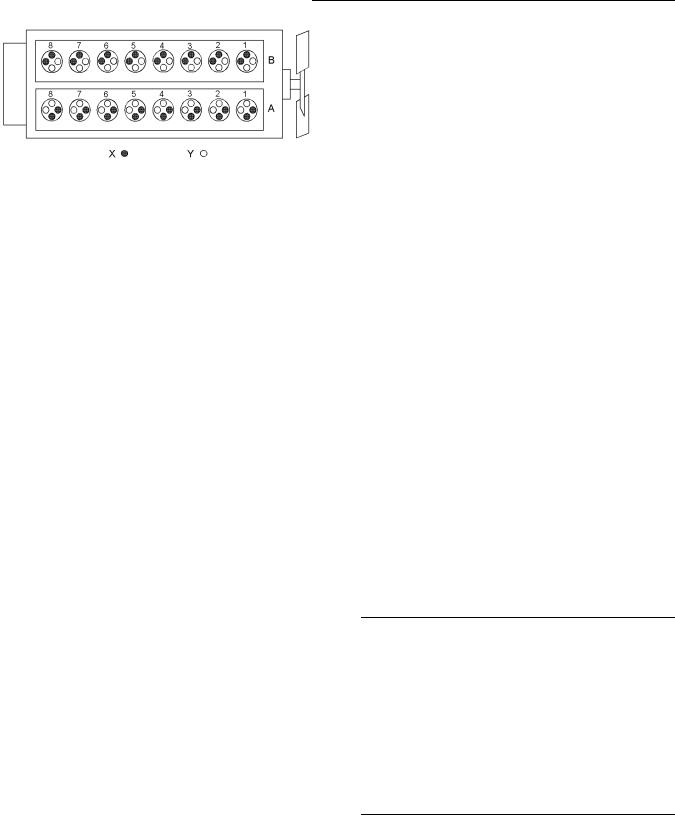
Illustration 14 |
g01210841 |
|
|
Sixteen cylinder |
|
(X)Inlet valves
(Y)Exhaust valves

SEBU8430 |
17 |
Product Information Section
Model Views and Specifications
Table 1
4016 Engine Specifications
Rated rpm |
1500 |
|
|
Number of Cylinders |
16 |
|
|
Configuration |
Vee-form |
|
|
Bore |
160 mm (6.299 inch) |
|
|
Stroke |
190 mm (7.480 inch) |
|
|
Displacement |
61.123 L (3729.954 in3) |
Compression ratio |
13:1 |
|
|
Aspiration |
Turbocharged |
|
|
Rotation (flywheel end) |
Counterclockwise |
|
|
Inlet valve lash (cold) |
0.40 mm (0.016 inch) |
|
|
Exhaust valve lash (cold) |
0.40 mm (0.016 inch) |
|
|
Firing order |
1A-1B-3A-3B-7A-7B- |
|
5A-5B-8A-8B-6A-6B- |
|
2A-2B-4A-4B |
18 |
SEBU8430 |
Product Information Section |
|
Product Identification Information |
|
Product Identification
Information
i02978102
Plate Locations and Film Locations
Engine Identification
Perkins engines are identified by an engine serial number.
A typical example of an engine serial number is DIH R**** U10001S.
D _________________________________________Made in Stafford I ______________________________________Application (Table 2) H _______________________________Type of engine (Table 3)
R _________________________Number of cylinders (Table 4)
***** __________________________________Fixed build number U ____________________________Built in the United Kingdom 00001 ____________________________________Engine Number S _____________________________________Year of Manufacture
Table 2
|
Application |
|
|
G |
Genset |
|
|
I |
Gas |
|
|
Table 3 |
|
|
|
|
Type of engine (Gas) |
|
|
F |
TESI Gas unit |
|
|
E |
TESI Combined Heat and Power unit |
|
|
G |
4016-E61-TRS |
|
|
H |
TRS Combined Heat and Power Unit |
|
|
J |
TRS Gas Unit |
|
|
Table 4
Number of Cylinders
F 6
H 8
M 12
R 16
Perkins dealers and Perkins distributors require all of these numbers in order to determine the components that were included in the engine. This permits accurate identification of replacement part numbers.
Serial Number Plate
Illustration 15 |
g01266904 |
|
|
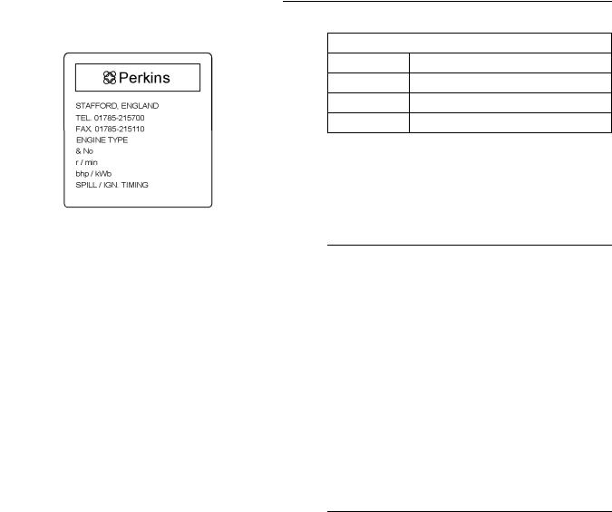
Serial number plate |
|
The engine serial number plate contains the following information:
•Place of manufacture
•Telephone number of manufacturer
•Fax number of manufacturer
•Type of engine
•Engine serial number
•Rated speed
•Power output
•Engine timing
•Rating
SEBU8430 |
19 |
|
Product Information Section |
|
Product Identification Information |
|
|
|
|
Illustration 16 |
g01229580 |
|
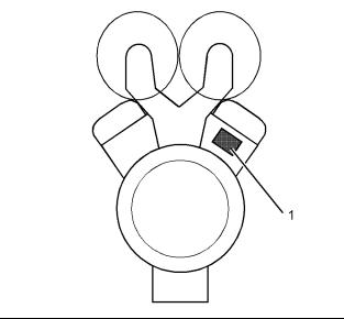
The location of the serial number plate for vee-form engines
The serial number plate (1) on a vee-form engine is located on the rear face of the cylinder block (bank A). See Illustration 16.
20 |
SEBU8430 |
Operation Section |
|
Lifting and Storage |
|
Operation Section
Lifting and Storage
i02885807
Product Lifting
NOTICE
Never bend the eyebolts and the brackets. Only load the eyebolts and the brackets under tension. Remember that the capacity of an eyebolt is less as the angle between the supporting members and the object becomes less than 90 degrees.
To remove the engine ONLY, use the lifting eyes that are on the engine. If necessary, remove engine components in order to avoid damage from the lifting device.
Lifting eyes are designed and installed for specific engine arrangements. Alterations to the lifting eyes and/or the engine make the lifting eyes and the lifting fixtures obsolete. If alterations are made, ensure that correct lifting devices are provided. Consult your Perkins dealer or your Perkins distributor for information regarding fixtures for correct engine lifting.
i03139740
Product Storage
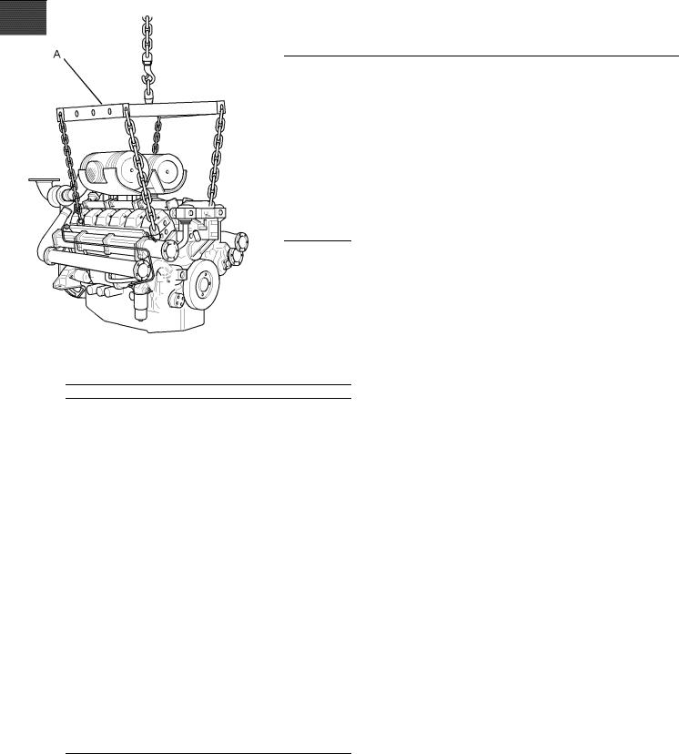
When it is necessary to remove a component at an angle, only use a link bracket that is properly rated for the weight.
Illustration 17 |
g01230422 |
|
|
Typical example |
|
Use a hoist to remove heavy components. Use a lifting beam (A) to lift the engine. All supporting members (chains and cables) should be parallel to each other. The chains and cables should be perpendicular to the top of the object that is being lifted.
Refer to Perkins Engine Company limited, Stafford for information on engine storage.
There are three different levels of engine storage. Level “A, B and C”.
Level “A ”
Level “A” will give protection for 12 month for diesel engines and 12 month protection for gas engines. This is for engines that are transported by a container or a truck. Level “A” is for the transportation of items that are within the United kingdom and within Europe.
Level “B ”
This level is additional to level “A”. Level “B ” will give protection under normal storage condition from −15° to +55°C (5° to 99°F) and “90%” relative humidity for two years. Level “B” is for the transportation of items overseas.
Level “C ”
In order to protect the product to Level “C”, contact Perkins Engines Company Limited Stafford.
SEBU8430 |
21 |
|
Operation Section |
|
Gauges and Indicators |
Gauges and Indicators
i02917145
Gauges and Indicators
Gauges are supplied by the OEM. For more information about the gauge package, see the OEM information.
Gauges provide indications of engine performance. Ensure that the gauges are in good working order. Determine the normal operating range by observing the gauges over a period of time.
Noticeable changes in gauge readings indicate potential gauge or engine problems. Problems may also be indicated by gauge readings that change even if the readings are within specifications. Determine and correct the cause of any significant change in the readings. Consult your Perkins dealer or your Perkins distributor for assistance.
NOTICE
If no oil pressure is indicated, STOP the engine. If maximum coolant temperature is exceeded, STOP the engine. Engine damage can result.
Engine Oil Pressure – The range for the engine oil pressure is 415 to 450 kPa (60 to 65 psi).
Jacket Water Coolant Temperature –
Typical water temperature into the engine is 71°C (160°F). Higher temperatures
may occur under certain conditions. The water temperature reading may vary according to load. The reading should never exceed 96°C (204°F).
1.A high water temperature switch is installed in the cooling system.
2.A low oil pressure switch is installed in the oil gallery of the engine.
3.A high pressure Backfire switch is installed to the inlet manifold of the engine.

22 |
SEBU8430 |
Operation Section |
|
Features and Controls |
|
Features and Controls
i02885816
Performance Parameters
Air/Fuel Ratio
The correct air/fuel ratio is very important for the following considerations:
•Margin of detonation
•Control of emissions
•Engine performance
•Achieving optimum service life for the engine
•Compliance with legal requirements
If the air/fuel ratio is not appropriate for the fuel and the operating conditions, a failure of the engine may occur. The service life of the turbochargers, the valves, and other components may be reduced.
Fuel Supply Pressure and Temperature
i02894958
Sensors and Electrical Components
Electronic Ignition System (EIS)
The Electronic Ignition System includes the following components:
•The control module for the ignition
•Timing sensor
•Ignition coil on each cylinder
•Spark plugs
•Ignition harness
The ignition system generates high voltage. Do not come in contact with the ignition system with the engine in operation. This voltage can cause personal injury or death.
The gas supply to the control valve for the air/fuel ratio must be between 5 to 25 kPa (0.72 to 3.6 psi). If a higher pressure is required a separate gas regulator must be installed into the fuel line.
The temperature of the gas into the air/fuel ratio control system must be between 5 to 40 °C (41 to 104°F).
Note: No zero pressure regulator is required with the air/fuel ratio control system for the 4016-61TRS engine.
Air, Charge Cooler Water
Temperature and Altitude
Refer to technical date sheet for the charts for the derate in order to determine the maximum
temperatures into the engine and the altitude derate.
The EIS control module is a sealed unit with no serviceable parts. The timing sensor uses the magnets that are mounted on the camshaft in order to generate the timing pulses. One pulse for each cylinder plus an index magnet in order to indicate the start of each cycle. The EIS control module has a output to each ignition coil. To initiate combustion in each cylinder, the EIS sends a pulse to the primary winding of the ignition coil. The coil increases the voltage on the secondary winding which creates a spark across the spark plug electrode.
The electronic ignition system provides control for the following activities:
•Ignition timing
•Ignition energy
•Protection from detonation
Switches
The engine is installed with the following switches.
•High cooling water temperature switch
•Low oil pressure switch
•High pressure switch for the manifold

SEBU8430 |
23 |
|
Operation Section |
|
Features and Controls |
Governor
The engine is installed with a digital governor that includes the following components:
•Digital governor
•Actuators and throttle valves
•Magnetic pickup
•Wiring harness
The governor uses the magnetic pickup to sense engine speed from the flywheel gear teeth. This signal is fed into the governor, which drives an actuator. This is connected to the throttle valves in order to control the amount of combustion gas/air.
A DC Desk service tool with the appropriate software key and cable are required in order to perform any adjustments to the system.
Engines may be equipped with optional engine protective devices that are not included in this section. This section contains some general information about the function of typical engine protective devices.
Alarms and shutoffs are electronically controlled. The operation of all alarms and shutoffs utilize components which are actuated by a sensing unit. The alarms and shutoffs are set at critical operating temperatures, pressures, or speeds in order to protect the engine from damage.
The alarms function in order to warn the operator when an abnormal operating condition occurs. The shutoffs function in order to shut down the engine when a more critical abnormal operating condition occurs. The shutoffs help to prevent damage to the engine.
Shutoffs may cause unburned gas to remain in the air inlet and in the exhaust manifold.
Detonation System
The equipment for the detonation system senses detonation or knock which may be caused by poor gas or may be caused by high combustion temperatures.
The detonation system includes the following components:
•Detonation sensor on each cylinder
•Control module for detonation
•Wiring harness
The detonation system operates by measuring vibrations on the crankcase. The signal is processed in order to eliminate normal engine vibrations. If detonation above a predetermined level is detected the ignition timing is retarded. If detonation ceases, the ignition timing that is retarded will be gradually brought back to a normal value. If the engine continues detonation the detonation system will operate in order to stop the engine.
i02427728
Alarms and Shutoffs
The OEM will supply this system. Refer to the OEM for more information.
Unburned gas in the air inlet and exhaust system may ignite when the engine is started. Personal injury and/or property damage may result.
Before starting an engine that may contain unburned gas, purge the unburned gas from the air inlet and exhaust system. Refer to the topic on purging unburned gas in the “Starting the Engine” section.
If an engine protective device shuts off the engine, always determine the cause of the shutoff. Make the necessary repairs before attempting to start the engine.
Become familiar with the following information:
•Types of the alarm and shutoff controls
•Locations of the alarm and shutoff controls
•Conditions which cause each control to function
•Resetting procedure that is required before starting the engine
Testing Alarms and Shutoffs
Alarms must function properly in order to provide timely warning to the operator. Shutoffs help to prevent damage to the engine. It is impossible to determine if the engine protective devices are in good working order during normal operation.
Malfunctions must be simulated in order to test the engine protective devices.
 Loading...