


402D

SEBU8311-01
April 2008
Operation and
Maintenance
Manual
402D-403D-404D Industrial Engine
GG
(Engine)
GH
(Engine)
GJ
(Engine)
GK
(Engine)
GL
(Engine)
GM
(Engine)
GN
(Engine)
GP
(Engine)
GQ
(Engine)
GS
(Engine)
This document has been printed from SPI². Not for Resale

Important Safety Information
Most accidents that involve product operation, maintenance and repair are caused by failure to
observe basic safety rules or precautions. An accident can often be avoided by recognizing potentially
hazardous situations before an accident occurs. A person must be alert to potential hazards. This
person should also have the necessary training, skills and tools to perform these functions properly.
Improper operation, lubrication, maintenance or repair of this product can be dangerous and
could result in injury or death.
Do not operate or perform any lubrication, maintenance or repair on this product, until you have
read and understood the operation, lubrication, maintenance and repair information.
Safety precautions and warnings are provided in this manual and on the product. If these hazard
warnings are not heeded, bodily injury or death could occur to you or to other persons.
The hazards are identified by the “Safety Alert Symbol” and followed by a “Signal Word” such as
“DANGER”, “WARNING” or “CAUTION”. The Safety Alert “WARNING” label is shown below.
The meaning of this safety alert symbol is as follows:
Attention! Become Alert! Your Safety is Involved.
The message that appears under the warning explains the hazard and can be either written or
pictorially presented.
Operations that may cause product damage are identified by “NOTICE” labels on the product and in
this publication.
Perkins cannot anticipate every possible circumstance that might involve a potential hazard. The
warnings in this publication and on the product are, therefore, not all inclusive. If a tool, procedure,
work method or operating technique that is not specifically recommended by Perkins is used,
you must satisfy yourself that it is safe for you and for others. You should also ensure that the
product will not be damaged or be made unsafe by the operation, lubrication, maintenance or
repair procedures that you choose.
The information, specifications, and illustrations in this publication are on the basis of information that
was available at the time that the publication was written. The specifications, torques, pressures,
measurements, adjustments, illustrations, and other items can change at any time. These changes can
affect the service that is given to the product. Obtain the complete and most current information before
you start any job. Perkins dealers or Perkins distributors have the most current information available.
When replacement parts are required for this
product Perkins recommends using Perkins
replacement parts.
Failure to heed this warning can lead to prema-
ture failures, product damage, personal injury or
death.
This document has been printed from SPI². Not for Resale

SEBU8311-01 3
Table of Contents
Table of Contents
Foreword ................................................................. 4
Safety Section
Safety Messages .................................................... 5
General Hazard Information ................................... 7
Burn Prevention ...................................................... 8
Fire Prevention and Explosion Prevention .............. 8
Crushing Prevention and Cutting Prevention ........ 10
Before Starting Engine ........................................... 11
Engine Starting ...................................................... 11
Engine Stopping .................................................... 11
Electrical System .................................................. 12
Product Information Section
Model Views ......................................................... 13
Product Identification Information ........................ 23
Operation Section
Lifting and Storage ................................................ 25
Gauges and Indicators .......................................... 28
Features and Controls .......................................... 29
Engine Starting ..................................................... 30
Engine Operation .................................................. 33
Engine Stopping ................................................... 34
Cold Weather Operation ....................................... 35
Maintenance Section
Refill Capacities .................................................... 39
Maintenance Interval Schedule ............................ 58
Warranty Section
Warranty Information ............................................ 89
Index Section
Index ..................................................................... 90
This document has been printed from SPI². Not for Resale

4 SEBU8311-01
Foreword
Foreword
Literature Information
This manual con
tains safety, operation instructions,
lubrication and maintenance information. This
manual should be stored in or near the engine area
in a literatur
e holder or literature storage area. Read,
study and keep it with the literature and engine
information.
English is the primary language for all Perkins
publications. The English used facilitates translation
and consiste
ncy.
Some photographs or illustrations in this manual
show details
or attachments that may be different
from your engine. Guards and covers may have
been removed for illustrative purposes. Continuing
improvemen
t and advancement of product design
may have caused changes to your engine which are
not included in this manual. Whenever a question
arises reg
arding your engine, or this manual, please
consult with your Perkins dealer or your Perkins
distributor for the latest available information.
Safety
This safety section lists basic safety precautions.
In addition, this section identifies hazardous,
warning si
tuations. Read and understand the basic
precautions listed in the safety section before
operating or performing lubrication, maintenance and
repair on
this product.
Operatio
n
Operating techniques outlined in this manual are
basic. Th
ey assist with developing the skills and
techniques required to operate the engine more
efficiently and economically. Skill and techniques
develop
as the operator gains knowledge of the
engine and its capabilities.
The oper
ation section is a reference for operators.
Photographs and illustrations guide the operator
through procedures of inspecting, starting, operating
and sto
pping the engine. This section also includes a
discussion of electronic diagnostic information.
Maintenance
The mai
ntenance section is a guide to engine care.
The illustrated, step-by-step instructions are grouped
by service hours and/or calendar time maintenance
interv
als. Items in the maintenance schedule are
referenced to detailed instructions that follow.
Recommended se
rvice should be performed at the
appropriate intervals as indicated in the Maintenance
Interval Schedule. The actual operating environment
of the engine a
lso governs the Maintenance Interval
Schedule. Therefore, under extremely severe,
dusty, wet or freezing cold operating conditions,
more frequen
t lubrication and maintenance than is
specified in the Maintenance Interval Schedule may
be necessary.
The maintenance schedule items are organized for
a preventive maintenance management program. If
the prevent
ive maintenance program is followed, a
periodic tune-up is not required. The implementation
of a preventive maintenance management program
should mini
mize operating costs through cost
avoidances resulting from reductions in unscheduled
downtime and failures.
Maintenance Intervals
Perform maintenance on items at multiples of
the original requirement. We recommend that the
maintenan
ce schedules be reproduced and displayed
near the engine as a convenient reminder. We also
recommend that a maintenance record be maintained
as part of
the engine’s permanent record.
Your authorized Perkins dealer or your Perkins
distribu
tor can assist you in adjusting your
maintenance schedule to meet the needs of your
operating environment.
Overhaul
Major engine overhaul details are not covered in
the Operation and Maintenance Manual except
for the i
nterval and the maintenance items in that
interval. Major repairs should only be carried out by
Perkins authorized personnel. Your Perkins dealer
or your P
erkins distributor offers a variety of options
regarding overhaul programs. If you experience
a major engine failure, there are also numerous
after f
ailure overhaul options available. Consult with
your Perkins dealer or your Perkins distributor for
information regarding these options.
California Proposition 65 Warning
Diesel engine exhaust and some of its constituents
are known to the State of California to cause cancer,
birth
defects, and other reproductive harm. Battery
posts, terminals and related accessories contain lead
and lead compounds. Wash hands after handling.
This document has been printed from SPI². Not for Resale
SEBU8311-01 5
Safety Section
Safety Messages
Safety Section
i02959960
Safety Message s
There may be s
everal specific warning signs on your
engine. The exact location and a description of the
warning signs are reviewed in this section. Please
become famil
iar with all warning signs.
Ensure that all of the warning signs are legible. Clean
the warning s
igns or replace the warning signs if
the words cannot be read or if the illustrations are
not visible. Use a cloth, water, and soap to clean
the warning
signs. Do not use solvents, gasoline, or
other harsh chemicals. Solvents, gasoline, or harsh
chemicals could loosen the adhesive that secures the
warning si
gns. The warning signs that are loosened
could drop off of the engine.
Replace an
y warning sign that is damaged or
missing.Ifawarningsignisattachedtoapartofthe
engine that is replaced, install a new warning sign on
the replac
ement part. Your Perkins dealer or your
distributor can provide new warning signs.
(A) Universal Warning
Do not operate or work on this equipment unless
you have r
ead and understand the instructions
and warnings in the Operation and Maintenance
Manuals. Failure to follow the instructions or
heed the
warnings could result in serious injury
or death.
g01154807
Illustration 1
Typica
lexample
Warning label (
A) is installed in different locations.
The location will change according to the physical
size of the engine.
This document has been printed from SPI². Not for Resale
6 SEBU8311-01
Safety Section
Safety Messages
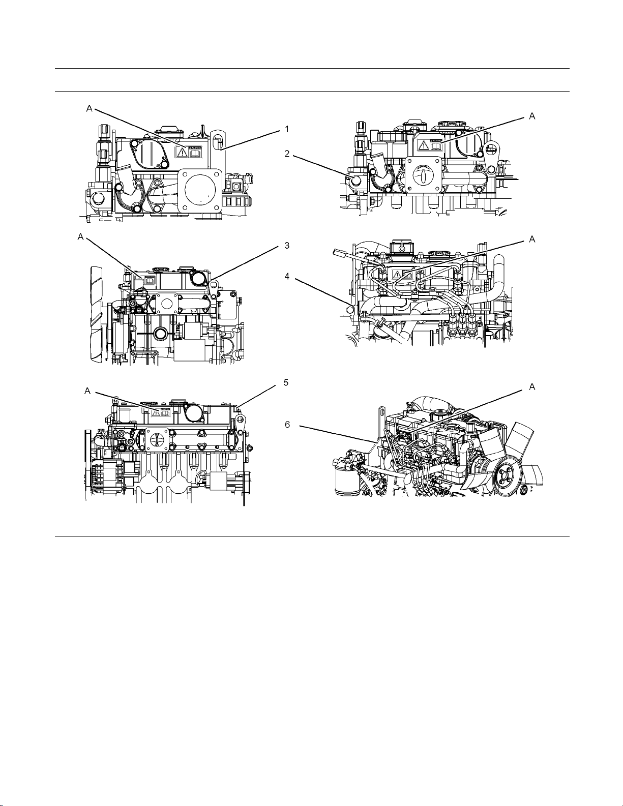
g01324126
Illustration 2
(A) Location of warning label
(1) 402D-05
(2) 403D-07
(3) 403D-11
(4) 403D-15, 403D-15T and 403D-17
(5) 404D-15
(6) 404D-22, 404D-22T and 404D-22TA
This document has been printed from SPI². Not for Resale
SEBU8311-01 7
Safety Section
General Hazard Information
i02328435
General Hazard Information
g00104545
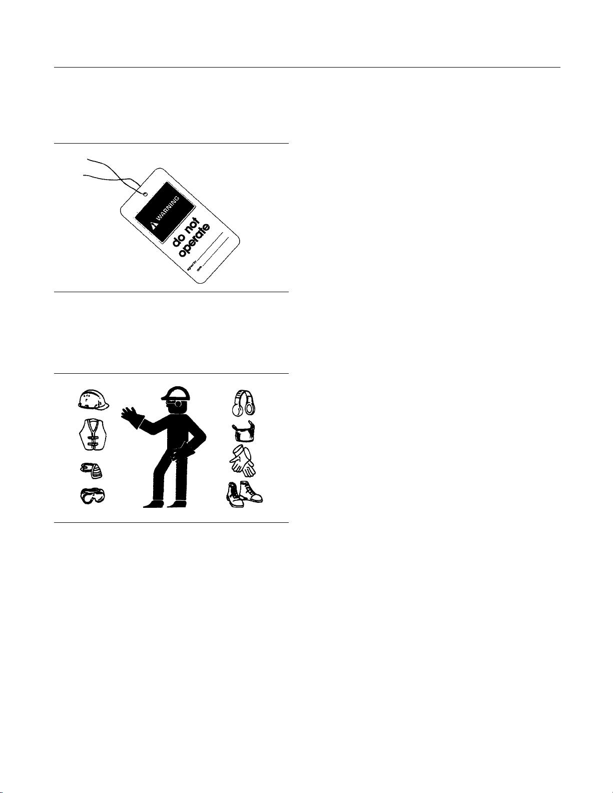
Illustration 3
Attach a “Do Not Operate” warning tag or a similar
warning tag to the start switch or to the controls
before you s
ervice the equipment or before you
repair the equipment.
g0070202
0
Illustration 4
Wear a hard hat, protective glasses, and other
protective equipment, as required.
Do not wear loose clothing or jewelry that can snag
on controls or on other parts of the engine.
Make sure that all protective guards and all covers
are secured in place on the engine.
Keep the engine free from foreign material. Remove
debris, oil, tools, and other items from the deck, from
walkway
s, and from steps.
Never put maintenance fluids into glass containers.
Drain al
l liquids into a suitable container.
Obey all local regulations for the disposal of liquids.
Use all cleaning solutions with care.
Report all nece
ssary repairs.
Do not allow unauthorized personnel on the
equipment.
Ensure that the power supply is disconnected before
youworkonthe
bus bar or the glow plugs.
Perform maintenance on the engine with the
equipment in t
he servicing position. Refer to the
OEM information for the procedure for placing the
equipment in the servicing position.
Pressure Air and Water
Pressurized air and/or water can cause debris
and/or hot water to be blown out. This could result in
personal inj
ury.
The direct application of pressurized air or
pressurize
d water to the body could result in personal
injury.
When pressu
rized air and/or water is used for
cleaning, wear protective clothing, protective shoes,
and eye protection. Eye protection includes goggles
or a protect
ivefaceshield.
The maximum air pressure for cleaning purposes
must be belo
w 205 kPa (30 psi). The maximum
water pressure for cleaning purposes must be below
275 kPa (40 psi).
Fluid Penetration
Pressure can be trapped in the hydraulic circuit long
after the engine has been stopped. The pressure can
cause hyd
raulic fluid or items such as pipe plugs to
escape rapidly if the pressure is not relieved correctly.
Do not rem
ove any hydraulic components or parts
until pressure has been relieved or personal injury
may occur. Do not disassemble any hydraulic
componen
ts or parts until pressure has been relieved
or personal injury may occur. Refer to the OEM
information for any procedures that are required to
relieve
the hydraulic pressure.
This document has been printed from SPI². Not for Resale
8 SEBU8311-01
Safety Section
Burn Prevention
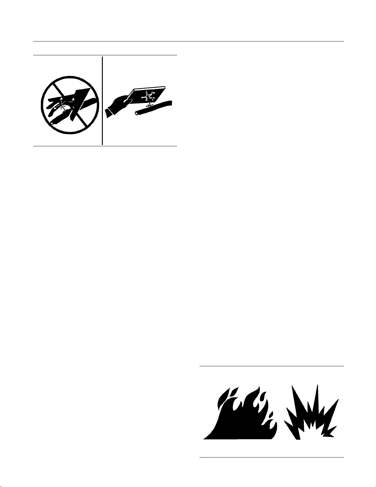
g00687600
Illustration 5
Always use a board or cardboard when you check
for a leak. Leaking fluid that is under pressure can
penetrate body tissue. Fluid penetration can cause
serious injury and possible death. A pin hole leak can
cause severe injury. If fluid is injected into your skin,
you must get treatment immediately. Seek treatment
from a doctor that is familiar with this type of injury.
Containing Fluid Spillage
Care must be taken in order to ensure that fluids
are contained during performance of inspection,
maintenance, testing, adjusting and repair of the
engine. Make provision to collect the fluidwitha
suitable container before any compartment is opened
or before any component is disassembled.
•
Only use the tools that are suitable for collecting
fluids and equipment that is suitable for collecting
fluids.
•
Only use the tools that are suitable for containing
fluids and equipment that is suitable for containing
fluids.
Obey all local regulations for the disposal of liquids.
i02143195
Burn Pre
vention
Do not touch any part of an operating engine.
Allow the engine to cool before any maintenance
is perfo
rmed on the engine. Relieve all pressure
in the air system, in the hydraulic system, in the
lubrication system, in the fuel system, or in the
coolin
g system before any lines, fittings or related
items are disconnected.
Coolant
When the engine is at operating temperature, the
engine coolant is hot. The coolant is also under
pressure. The radiator and all lines to the heaters or
to the engine contain hot coolant.
Any contact with hot coolant or with steam can cause
severe burns. Allow cooling system components to
cool before the cooling system is drained.
Check the coolant level after the engine has stopped
and the engine has been allowed to cool.
Ensure that the filler cap is cool before removing the
filler cap. The filler cap must be cool enough to touch
with a bare hand. Remove the filler cap slowly in
order to relieve pressure.
Cooling system conditioner contains alkali. Alkali can
cause personal injury. Do not allow alkali to contact
the skin, the eyes, or the mouth.
Oils
Hot oil and hot lubricating components can cause
personal injury. Do not allow hot oil to contact the
skin. Also, do not allow hot components to contact
the skin.
Batteries
Electrolyte is an acid. Electrolyte can cause personal
injury. Do not allow electrolyte to contact the skin or
the eyes. Always wear protective glasses for servicing
batteries. Wash hands after touching the batteries
and connectors. Use of gloves is recommended.
i028134
88
Fire Prevention an d Explosion
Prevent
ion
g00704000
Illust
ration 6
This document has been printed from SPI². Not for Resale
SEBU8311-01 9
Safety Section
Fire Prevention and Explosion Prevention
All fuels, most
lubricants, and some coolant mixtures
are flammable.
Flammable flui
ds that are leaking or spilled onto hot
surfaces or onto electrical components can cause
a fire. Fire may cause personal injury and property
damage.
A flash fire may result if the covers for the engine
crankcase ar
e removed within fifteen minutes after
an emergency shutdown.
Determine wh
ether the engine will be operated in an
environment that allows combustible gases to be
drawn into the air inlet system. These gases could
cause the eng
ine to overspeed. Personal injury,
property damage, or engine damage could result.
If the appli
cation involves the presence of combustible
gases, consult your Perkins dealer and/or your
Perkins distributor for additional information about
suitable p
rotection devices.
Remove all flammable combustible materials or
conductiv
e materials such as fuel, oil, and debris from
the engine. Do not allow any flammable combustible
materials or conductive materials to accumulate on
the engine
.
Store fuels and lubricants in correctly marked
container
s away from unauthorized persons. Store
oily rags and any flammable materials in protective
containers. Do not smoke in areas that are used for
storing fl
ammable materials.
Do not expose the engine to any flame.
Exhaust shields (if equipped) protect hot exhaust
components from oil or fuel spray in case of a line,
a tube, or
a seal failure. Exhaust shields must be
installed correctly.
Do not we
ld on lines or tanks that contain flammable
fluids. Do not flame cut lines or tanks that contain
flammable fluid. Clean any such lines or tanks
thoroug
hly with a nonflammable solvent prior to
welding or flame cutting.
Wiring m
ust be kept in good condition. All electrical
wires must be correctly routed and securely attached.
Check all electrical wires daily. Repair any wires
that ar
e loose or frayed before you operate the
engine. Clean all electrical connections and tighten
all electrical connections.
Eliminate all wiring that is unattached or unnecessary.
Do not use any wires or cables that are smaller than
the rec
ommended gauge. Do not bypass any fuses
and/or circuit breakers.
Arcing or spark
ing could cause a fire. Secure
connections, recommended wiring, and correctly
maintained battery cables will help to prevent arcing
or sparking.
Inspect all lines and hoses for wear or for
deteriorati
on. The hoses must be correctly routed.
The lines and hoses must have adequate support
and secure clamps. Tighten all connections to the
recommended
torque. Leaks can cause fires.
Oil filters and fuel
filters must be correctly installed.
The filter hou
sings must be tightened to the correct
torque.
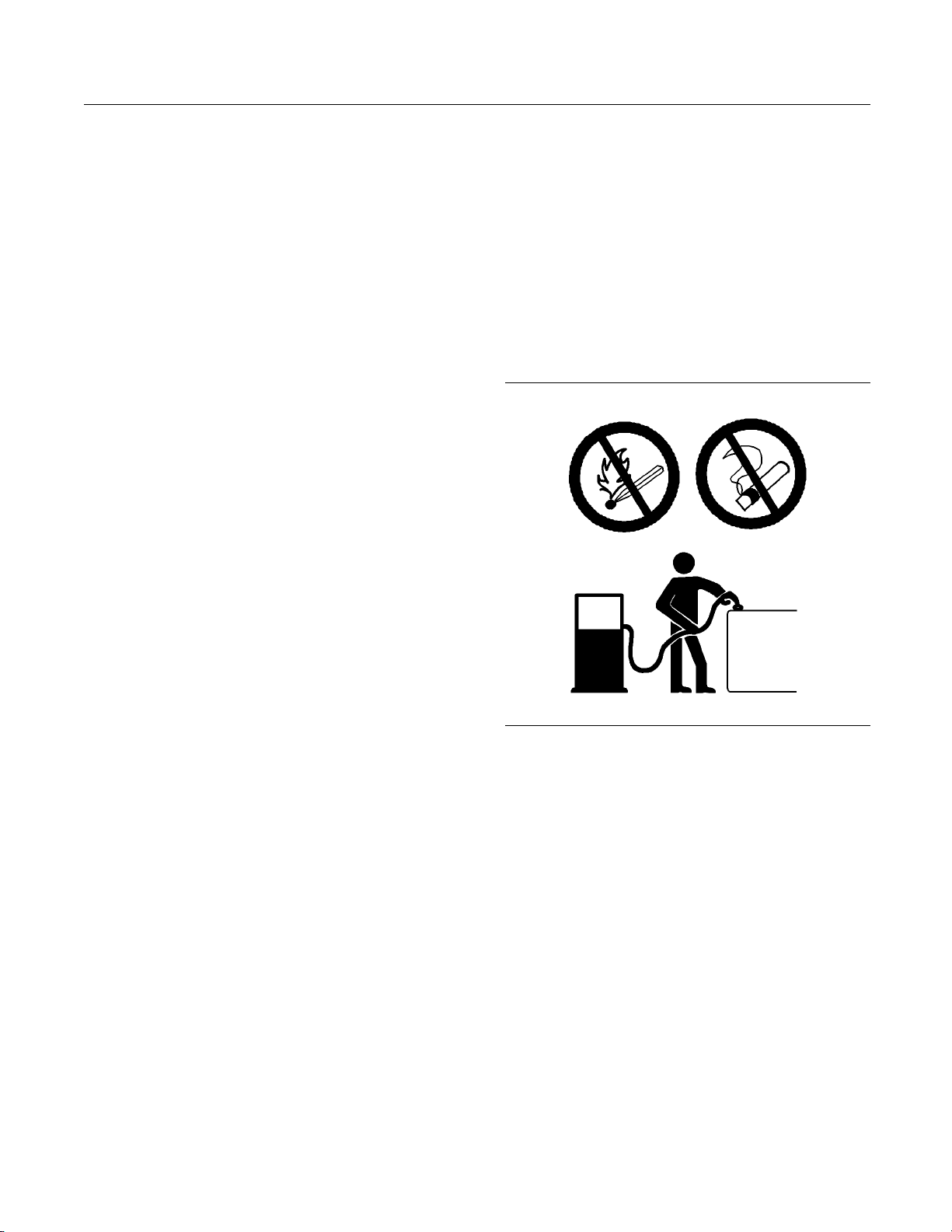
g00704059
Illustration 7
Use caution when you are refueling an engine. Do
not smoke while you are refueling an engine. Do not
refuel an engine near open flames or sparks. Always
stop the engine before refueling.
This document has been printed from SPI². Not for Resale
10 SEBU8311-01
Safety Section
Crushing Prevention and Cutting Prevention
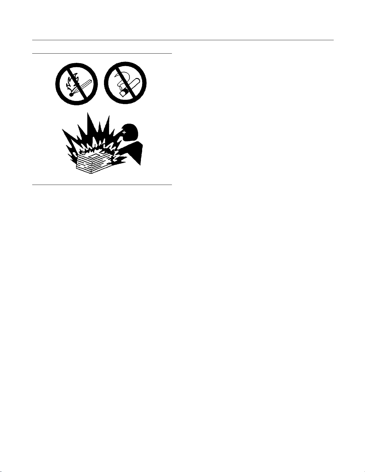
g00704135
Illustration 8
Gases from a battery can explode. Keep any open
flames or sparks away from the top of a battery. Do
not smoke in battery charging areas.
Never check the battery charge by placing a metal
object across the terminal posts. Use a voltmeter or
ahydrometer.
Incorrect jumper cable connections can cause
an explosion that can result in injury. Refer to
the Operation Section of this manual for specific
instructions.
Do not charge a frozen battery. This may cause an
explosion.
The batteries must be kept clean. The covers
(if equipped) must be kept on the cells. Use the
recommended cables, connections, and battery box
covers when the engine is operated.
Fire Extinguisher
Make sure that a fire extinguisher is available. Be
familiar with the operation of the fire extinguisher.
Inspect the fire extinguisher and service the fire
extinguisher regularly. Obey the recommendations
on the instruction plate.
Lines, Tubes and Hoses
Do not bend high pressure lines. Do not strike high
pressure lines. Do not install any lines that are bent
or damaged. Do not clip any other items to the high
pressure lines.
Repair any line
s that are loose or damaged. Leaks
can cause fires. Consult your Perkins dealer or your
Perkins distributor for repair or for replacement parts.
Check lines, tubes and hoses carefully. Do not use
your bare hand to check for leaks. Use a board or
cardboard to
check for leaks. Tighten all connections
to the recommended torque.
Replace the p
arts if any of the following conditions
are present:
•
End fittings a
re damaged or leaking.
•
Outer coverings are chafed or cut.
•
Wires are exposed.
•
Outer coveri
ngs are ballooning.
•
Flexible part of the hoses are kinked.
•
Outer covers have embedded armoring.
•
End fittings a
re displaced.
Make sure that all clamps, guards, and heat shields
are installe
d correctly. During engine operation, this
will help to prevent vibration, rubbing against other
parts, and excessive heat.
i02143194
Crushing Prevention and
Cutting Prevention
Support th
e component correctly when work beneath
the component is performed.
Unless oth
er maintenance instructions are provided,
never attempt adjustments while the engine is
running.
Stay clear of all rotating parts and of all moving
parts. Leave the guards in place until maintenance
is perfor
med. After the maintenance is performed,
reinstall the guards.
Keep obje
cts away from moving fan blades. The fan
blades will throw objects or cut objects.
When obje
cts are struck, wear protective glasses in
order to avoid injury to the eyes.
Chips or o
ther debris may fly off objects when objects
are struck. Before objects are struck, ensure that no
one will be injured by flying debris.
This document has been printed from SPI². Not for Resale

SEBU8311-01 11
Safety Section
Before Starting Engine
i02813489
Before Starting Engine
Before the init
ial start-up of an engine that is new,
serviced or repaired, make provision to shut the
engine off, in order to stop an overspeed. This may
be accomplish
ed by shutting off the air and/or fuel
supply to the engine.
Overspeed shu
tdown should occur automatically for
engines that are controlled electronically. If automatic
shutdown does not occur, press the emergency stop
buttoninord
er to cut the fuel and/or air to the engine.
Inspect the engine for potential hazards.
Before starting the engine, ensure that no one is on,
underneath, or close to the engine. Ensure that the
area is free
of personnel.
If equipped, ensure that the lighting system for the
engine is su
itable for the conditions. Ensure that all
lights work correctly, if equipped.
All protect
ive guards and all protective covers must
be installed if the engine must be started in order
to perform service procedures. To help prevent an
accident t
hat is caused by parts in rotation, work
around the parts carefully.
Do not bypa
ss the automatic shutoff circuits. Do not
disable the automatic shutoff circuits. The circuits are
provided in order to help prevent personal injury. The
circuits
are also provided in order to help prevent
engine damage.
See the Se
rvice Manual for repairs and for
adjustments.
i02157354
Engine Starting
Do not use aerosol types of starting aids such as
ether. Such use could result in an explosion and
personal injury.
If a warning tag is attached to the engine start switch
or to the controls, DO NOT start the engine or move
the controls. Consult with the person that attached
the warning tag before the engine is started.
All protective
guards and all protective covers must
be installed if the engine must be started in order
to perform service procedures. T o help prevent an
accident that
is caused by parts in rotation, work
around the parts carefully.
Start the eng
ine from the operator’s compartment or
from the engine start switch.
Always start
theengineaccordingtotheprocedure
that is described in the Operation and Maintenance
Manual, “Engine Starting” topic in the Operation
Section. Kno
wing the correct procedure will help to
prevent major damage to the engine components.
Knowing the procedure will also help to prevent
personal in
jury.
To ensure that the jacket water heater (if equipped)
and/or the l
ube oil heater (if equipped) is working
correctly, check the water temperature gauge and the
oil temperature gauge during the heater operation.
Engine exhaust contains products of combustion
which can be harmful to your health. Always start the
engine and
operate the engine in a well ventilated
area. If the engine is started in an enclosed area,
vent the engine exhaust to the outside.
Note: The engine is equipped with an automatic
device for cold starting for normal conditions of
operatio
n. If the engine will be operated in very cold
conditions, then an extra cold starting aid may be
required. Normally, the engine will be equipped with
the corre
ct type of starting aid for your region of
operation.
The 400 S
eries engines are equipped with a glow
plug starting aid in each individual cylinder that heats
the intake air in order to improve starting.
i02590389
Engine St opp ing
To avoid overheating of the engine and accelerated
wear of the engine components, stop the engine
according to this Operation and Maintenance Manual,
“Engine Stopping” topic (Operation Section).
Use the Emergency Stop Button (if equipped)
ONLY in an emergency situation. DO N OT use the
Emergency Stop Button for normal engine stopping.
After an emergency stop, DO NOT start the engine
until the problem that caused the emergency stop
has been corrected.
This document has been printed from SPI². Not for Resale

12 SEBU8311-01
Safety Section
Electrical System
On the initial s
tart-up of a new engine or an engine
that has been serviced, make provisions to stop the
engine if an overspeed condition occurs. This may be
accomplished
by shutting off the fuel supply and/or
the air supply to the engine.
If equipped,
in order to stop an electronically
controlled engine, cut the power to the engine.
i02176668
Electrical System
Never disconnect any charging unit circuit or battery
circuit cable from the battery when the charging unit
is operating. A spark can cause the combustible
gases that are produced by some batteries to ignite.
To help prevent sparks from igniting combustible
gases that are produced by some batteries, the
negative “−” jump start cable should be connected
last from the external power source to the negative
“−” terminal of the starting motor. If the starting motor
is not equipped with a negative “−” terminal, connect
thejumpstartcabletotheengineblock.
Check the electrical wires daily for wires that are
loose or frayed. Tighten all loose electrical wires
before the engine is started. Repair all frayed
electrical wires before the engine is started. See
the Operation and Maintenance Manual for specific
starting instructions.
Grounding Practices
Correct grounding for the engine electrical system
is necessary for optimum engine performance
and reliability. Incorrect grounding will result in
uncontrolled electrical circuit paths and in unreliable
electrical circuit paths.
Uncontrolled electrical circuit paths can result in
damage to main bearings, to crankshaft bearing
journal surfaces, and to aluminum components.
Engines that are installed without engine-to-frame
ground straps can be damaged by electrical
discharge.
To ensure that the engine and the engine electrical
systems function correctly, an engine-to-frame
ground strap with a direct path to the battery must be
used. This path may be provided by way of a direct
engine ground to the frame.
All grounds should be tight and free of corrosion. The
engine alternator must be grounded to the negative
“-” battery terminal with a wire that is adequate to
handle the full charging current of the alternator.
This document has been printed from SPI². Not for Resale
SEBU8311-01 13
Product Information Section
Model Views
Product Information
Section
Model Views
i02590436
Model View Illustrations
The following model views show typical features
of the 400 series engines. Due to individual
applications, your engine may appear different from
the illustrations.
Note: Individual components are detailed on the
404D-22T turbocharged engine only.
g01299985
Illustration 9
Typical view of the 402D-05 engine
This document has been printed from SPI². Not for Resale
14 SEBU8311-01
Product Information Section
Model Views
g01300431
Illustration 10
Typical view of the 403D-15 T engine
This document has been printed from SPI². Not for Resale
SEBU8311-01 15
Product Information Section
Model Views
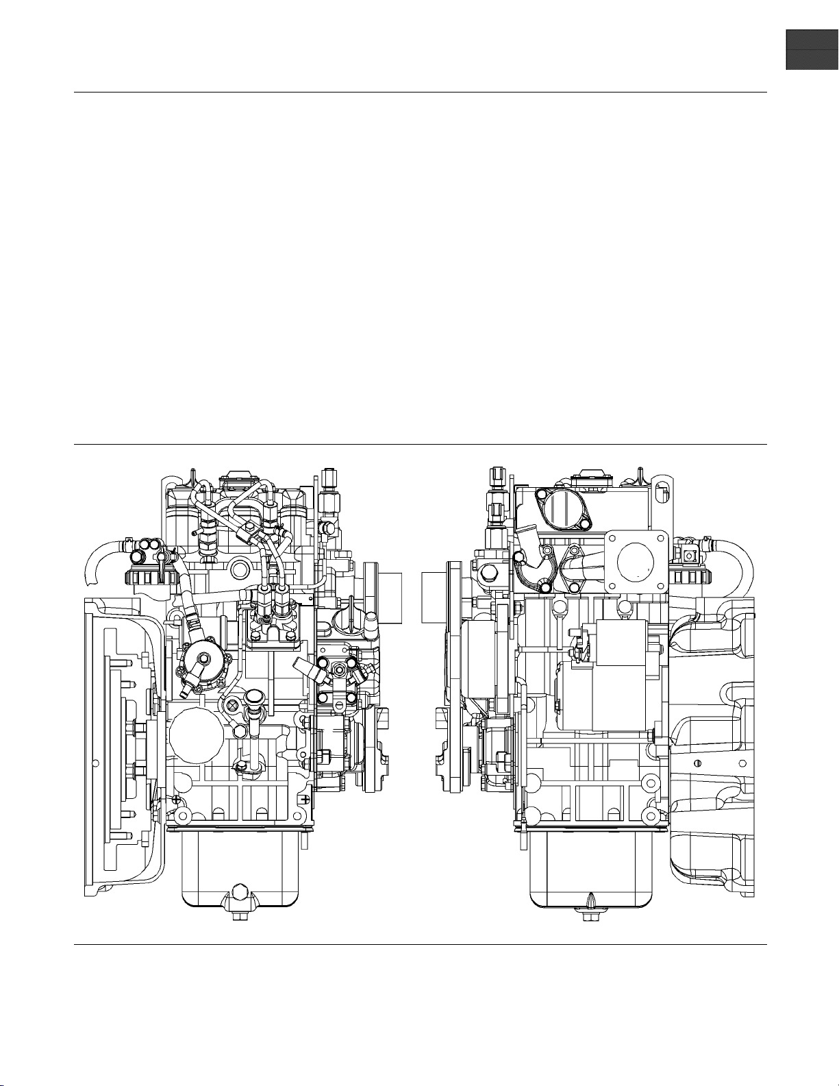
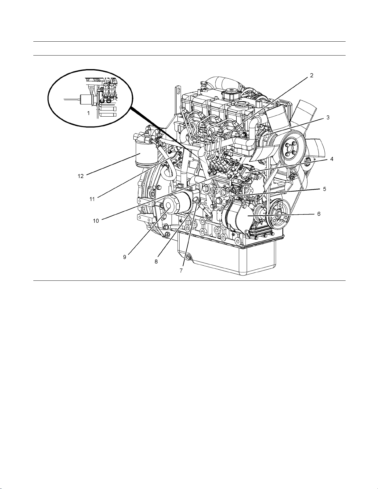
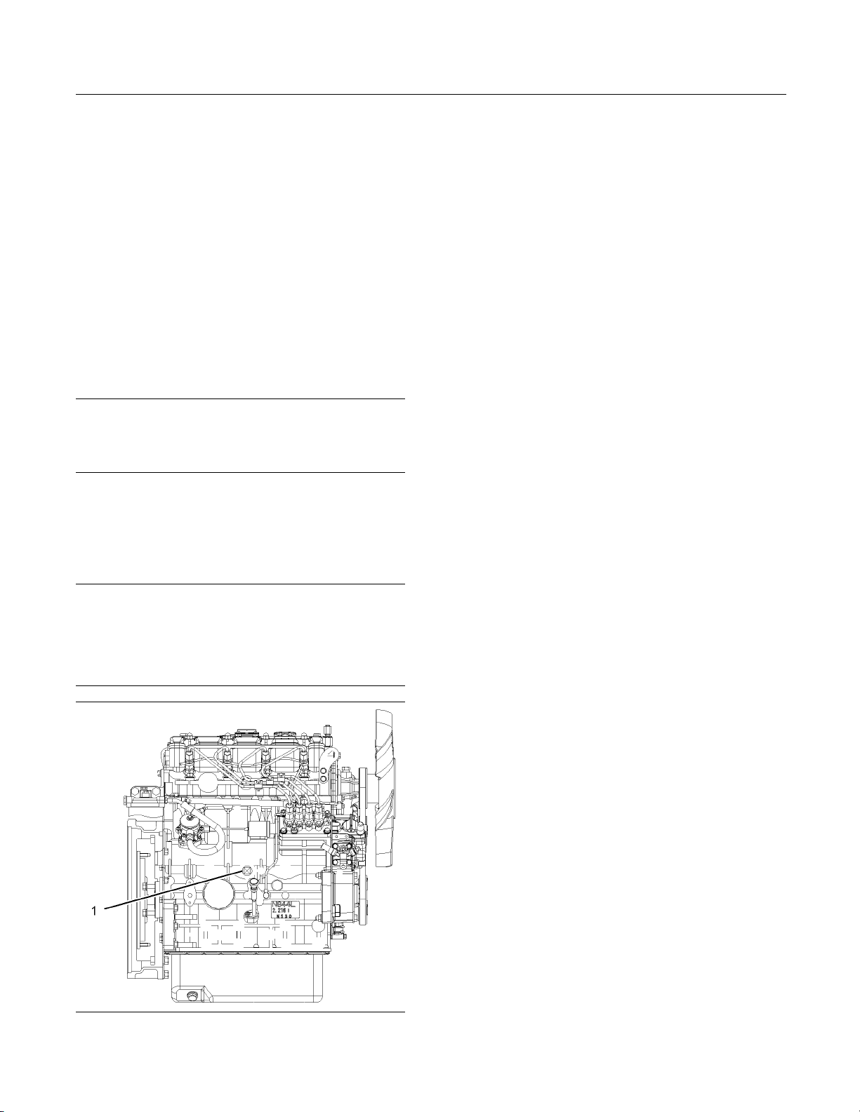
g01304893
Illustration 11
Front and right side view of the 404D-22T Engine
(1) Fuel shutoff solenoid
(2) Number one fuel injector
(3) Water pump
(4) Lower engine oil filler cap
(5) Throttle lever
(6) Cover plate for the a ccessory drive
(7) Engine oil level gauge
(8) Engine oil coo ler
(9) Engine oil filter
(10) Fuel injection pump
(11) Transfer pump
(12) Fuel filter
This document has been printed from SPI². Not for Resale
16 SEBU8311-01
Product Information Section
Model Views
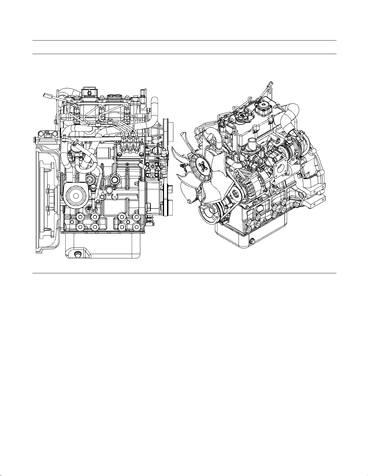
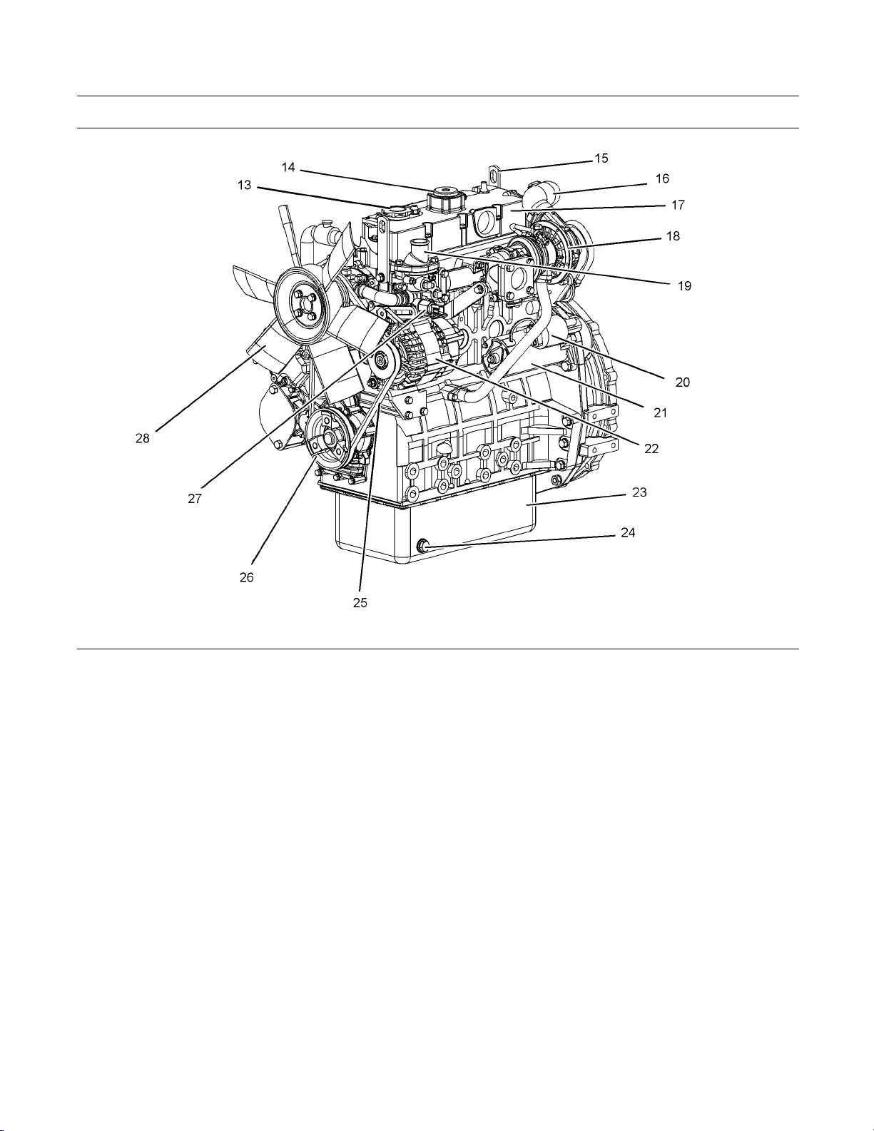
g01305224
Illustration 12
Front and left side view of the 404D-22T Engine
(13) Top engine oil filler c ap
(14) Crankcase breather
(15) Rear Lifting eye
(16) Air inlet elbow
(17) Valve mechanism cover
(18) Turbocharger
(19) Water temperature regulator hous ing
(20) Starting motor solenoid
(21) Electric starting motor
(22) Alternator
(23) Engine oil pan
(24) Engine oil drain plug
(25) Fan drive belt
(26) Crankshaft pulley
(27) Coolant tem perature switch
(28) Cooling fan
i02959055
Engine De script ion
The 400 series engines are indirect injection engines.
The engines are controlled with a mechanically
actuated fuel injection pump. The engine cylinders
are arranged in-line.
The cylinder head assembly has one inlet valve and
one exhaust valve for each cylinder. Each cylinder
valve has a single valve spring.
The pistons have two compression rings and an
oil control ring. It is important to ensure the correct
piston height so that the piston does not contact the
cylinder head. The correct piston height also ensures
efficient combustion of fuel that is necessary in order
to conform to requirements for emissions.
The crankshaft for a two cylinder engine has two
main bearing journals. The crankshaft for a three
cylinder engine has four main bearing journals. The
crankshaft for a four cylinder engine has five main
bearing journals. End play is controlled by the thrust
washers that are located on the rear main bearing.
This document has been printed from SPI². Not for Resale

SEBU8311-01 17
Product Information Section
Model Views
The timing gear
s are stamped with timing marks in
order to ensure the correct assembly of the gears.
WhentheNo.1pistonisattopcentercompression
stroke, the te
eth that are stamped on the crankshaft
gear and the camshaft gear will be in alignment with
the idler gear.
The crankshaft gear turns the idler gear which then
turns the camshaft gear and the gear for the engine
oil pump.
The fuel injection pump is mounted in the cylinder
block. The fu
el injection pump is operated by lobes
on the camshaft. The fuel transfer pump is located
on the right hand side of the cylinder block. The
fuel transf
er pump is also operated by lobes on the
camshaft.
The fuel inj
ection pump conforms to requirements
for emissions. If any adjustments to the fuel injection
pumptimingandhighidlearerequiredyoumust
refer to yo
ur Perkins distributoror your Perkins
dealer. Some fuel injection pumps have mechanical
governors that control the engine rpm. Some fuel
injection
pumps have a governor that is electrically
controlled.
A gerotor
oil pump is located in the center of the idler
gear. The engine oil pump sends lubricating oil to the
main oil gallery through a pressure relief valve and an
engine oi
l filter. The rocker arms receive pressurized
oil through an externally located oil line that runs from
the main oil gallery to the cylinder head.
Coolant from the bottom of the radiator passes
through the belt driven centrifugal water pump. The
coolant
is cooled by the radiator and the temperature
is regulated by a water temperature regulator.
Engine e
fficiency, efficiency of emission controls, and
engine performance depend on adherence to correct
operation and maintenance recommendations.
Engine
performance and efficiency also depend on
the use of recommended fuels, lubrication oils, and
coolants. Refer to the Operation and Maintenance
Manual
, “Maintenance Interval Schedule” for more
information on maintenance items.
Engine Specifications
Note: The front end of the engine is opposite the
flywheel end of the engine. The left and the right side
of the engine are determined from the flywheel end.
The No. 1 cylinder is the front cylinder.
This document has been printed from SPI². Not for Resale
18 SEBU8311-01
Product Information Section
Model Views
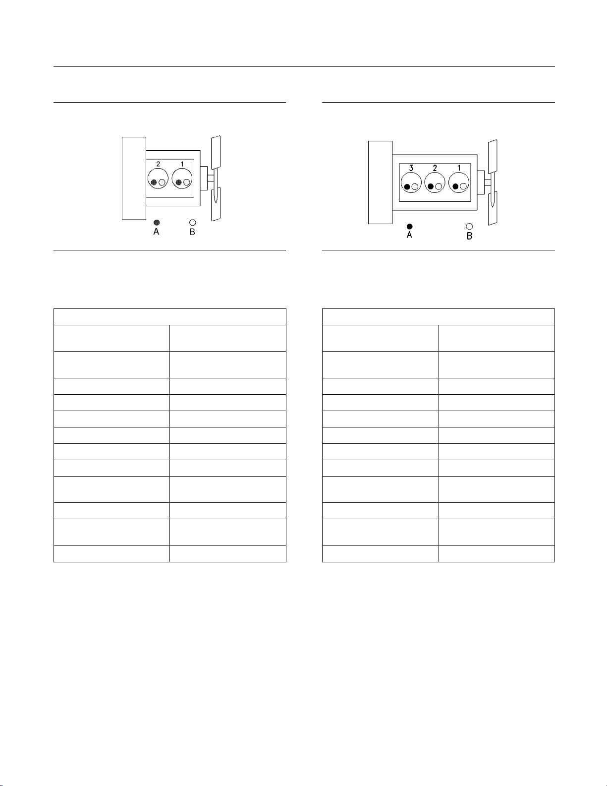
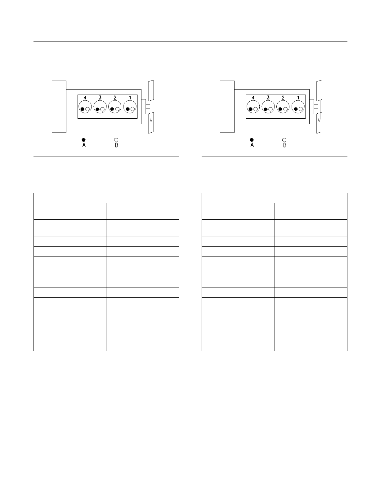
402D-05 Engine
g01108476
Illustratio
n13
(A) Ex haust valves
(B) I nlet valves
Table 1
402D-05 Engine Specifications
Maximum Operating
Speed (rpm)
3600 rpm
Cylinders and
Arrangement
In-Line two cylinder
Bore
67 mm (2.64 inch)
Stroke 72 mm (2.83 inch)
Displacement 0.507 L (30.939 in
3
)
Aspiration NA
(1)
Compression Ratio
23.5:1
Firing Order
1-2
Rotation that is viewed
from the fly
wheel
Counterclockwise
Valve Lash Setting (Inlet) 0.20 mm (0.008 inch)
Valve Lash Setting
(Exhaust)
0.20 mm (0.008 inch)
Injection Indirect
(1)
Naturally Aspirated
403D-07 Engine
g00852304
Illustratio
n14
(A) Exhaus t valves
(B) Inlet valves
Table 2
403D-07 Engine Specifications
Maximum Operating
Speed (rpm)
3600 rpm
Cylinders and
Arrangement
In-Line three cylinder
Bore
67 mm (2.64 inch)
Stroke 72 mm (2.83 inch)
Displacement 0.762 L (46.500 in
3
)
Aspiration NA
(1)
Compression Ratio
23.5:1
Firing Order
1-2-3
Rotation that is viewed
from the fly
wheel
Counterclockwise
Valve Lash Setting (Inlet) 0.20 mm (0.008 inch)
Valve Lash Setting
(Exhaust)
0.20 mm (0.008 inch)
Injection Indirect
(1)
Naturally A spirat ed
This document has been printed from SPI². Not for Resale

SEBU8311-01 19
Product Information Section
Model Views
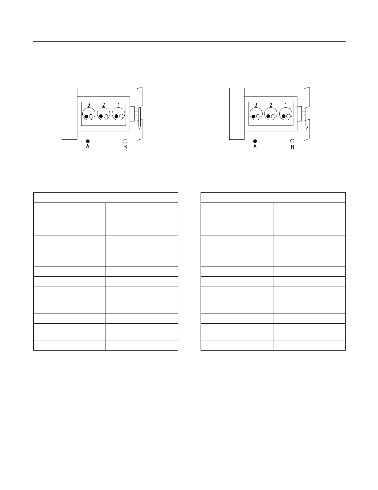
403D-11 Engine
g00852304
Illustratio
n15
(A) Ex haust valves
(B) I nlet valves
Table 3
403D-11 Engine Specifications
Maximum Operating
Speed (rpm)
3600 rpm
Cylinders and
Arrangement
In-Line three cylinder
Bore
77 mm (3.03 inch)
Stroke 81 mm (3.19 inch)
Displacement 1.131 L (69.018 in
3
)
Aspiration NA
(1)
Compression Ratio
23:1
Firing Order
1-2-3
Rotation that is viewed
from the fly
wheel
Counterclockwise
Valve Lash Setting (Inlet) 0.20 mm (0.008 inch)
Valve Lash Setting
(Exhaust)
0.20 mm (0.008 inch)
Injection Indirect
(1)
Naturally Aspirated
403D-15 Engine
g00852304
Illustratio
n16
(A) Exhaus t valves
(B) Inlet valves
Table 4
403D-15 Engine Specifications
Maximum Operating
Speed (rpm)
3000 rpm
Cylinders and
Arrangement
In-Line three cylinder
Bore
84 mm (3.31 inch)
Stroke 90 mm (3.54 inch)
Displacement 1.496 L (91.291 in
3
)
Aspiration NA
(1)
Compression Ratio
22.5:1
Firing Order
1-2-3
Rotation that is viewed
from the fly
wheel
Counterclockwise
Valve Lash Setting (Inlet) 0.20 mm (0.008 inch)
Valve Lash Setting
(Exhaust)
0.20 mm (0.008 inch)
Injection Indirect
(1)
Naturally A spirat ed
This document has been printed from SPI². Not for Resale
20 SEBU8311-01
Product Information Section
Model Views
403D-15T Engin
e
g00852304
Illustratio
n17
(A) Ex haust valves
(B) I nlet valves
Table 5
403D-15T Engine Specifications
Maximum Operating
Speed (rpm)
3000 rpm
Cylinders and
Arrangement
In-Line three cylinder
Bore
84 mm (3.31 inch)
Stroke 90 mm (3.54 inch)
Displacement 1.496 L (91.291 in
3
)
Aspiration T
(1)
Compression Ratio
22.5:1
Firing Order
1-2-3
Rotation that is viewed
from the fly
wheel
Counterclockwise
Valve Lash Setting (Inlet) 0.20 mm (0.008 inch)
Valve Lash Setting
(Exhaust)
0.20 mm (0.008 inch)
Injection Indirect
(1)
Turbocharged
403D-17 Engine
g00852304
Illustratio
n18
(A) Exhaus t valves
(B) Inlet valves
Table 6
403D-17 Engine Specifications
Maximum Operating
Speed (rpm)
2600 rpm
Cylinders and
Arrangement
In-Line three cylinder
Bore
84 mm (3.31 inch)
Stroke 100 mm (3.94 inch)
Displacement 1.66 L (101.3 in
3
)
Aspiration NA
(1)
Compression Ratio
23.1:1
Firing Order
1-2-3
Rotation that is viewed
from the fly
wheel
Counterclockwise
Valve Lash Setting (Inlet) 0.20 mm (0.008 inch)
Valve Lash Setting
(Exhaust)
0.20 mm (0.008 inch)
Injection Indirect
(1)
Naturally A spirat ed
This document has been printed from SPI². Not for Resale

SEBU8311-01 21
Product Information Section
Model Views
404D-15 Engine
g00296424
Illustratio
n19
(A) Ex haust valves
(B) I nlet valves
Table 7
404D-15 Engine Specifications
Maximum Operating
Speed (rpm)
3000 rpm
Cylinders and
Arrangement
In-Line four cylinder
Bore
77 mm (3.03 inch)
Stroke 81 mm (3.19 inch)
Displacement 1.508 L (92.024 in
3
)
Aspiration NA
(1)
Compression Ratio
23.5:1
Firing Order
1-3-4-2
Rotation that is viewed
from the fly
wheel
Counterclockwise
Valve Lash Setting (Inlet) 0.20 mm (0.008 inch)
Valve Lash Setting
(Exhaust)
0.20 mm (0.008 inch)
Injection Indirect
(1)
Naturally Aspirated
404D-22 Engine
g00296424
Illustratio
n20
(A) Exhaus t valves
(B) Inlet valves
Table 8
404D-22 Engine Specifications
Maximum Operating
Speed (rpm)
3000 rpm
Cylinders and
Arrangement
In-Line four cylinder
Bore
84.0 mm (3.31 inch)
Stroke 100.0 m m (3.94 inch)
Displacement 2.216 L (135.229 in
3
)
Aspiration NA
(1)
Compression Ratio
23.3:1
Firing Order
1-3-4-2
Rotation that is viewed
from the fly
wheel
Counterclockwise
Valve Lash Setting (Inlet) 0.20 mm (0.008 inch)
Valve Lash Setting
(Exhaust)
0.20 mm (0.008 inch)
Injection Indirect
(1)
Naturally A spirat ed
This document has been printed from SPI². Not for Resale
22 SEBU8311-01
Product Information Section
Model Views
404D-22T Engin
e
g00296424
Illustratio
n21
(A) Ex haust valves
(B) I nlet valves
Table 9
404D-22T Engine Specifications
Maximum Operating
Speed (rpm)
3000 rpm
Cylinders and
Arrangement
In-Line four cylinder
Bore
84.0 mm (3.31 inch)
Stroke 100.0 mm (3.94 inch)
Displacement 2.216 L (135.229 in
3
)
Aspiration T
(1)
Compression Ratio
23.5:1
Firing Order
1-3-4-2
Rotation that is viewed
from the fly
wheel
Counterclockwise
Valve Lash Setting (Inlet) 0.20 mm (0.008 inch)
Valve Lash Setting
(Exhaust)
0.20 mm (0.008 inch)
Injection Indirect
(1)
Turbocharged
404D-22TA Engi
ne
g00296424
Illustratio
n22
(A) Exhaus t valves
(B) Inlet valves
Table 10
404D-22TA Engine Specifications
Maximum Operating
Speed (rpm)
2800 rpm
Cylinders and
Arrangement
In-Line four cylinder
Bore
84.0 mm (3.31 inch)
Stroke 100.0 m m (3.94 inch)
Displacement 2.216 L (135.229 in
3
)
Aspiration TA
(1)
Compression Ratio
23.5:1
Firing Order
1-3-4-2
Rotation that is viewed
from the fly
wheel
Counterclockwise
Valve Lash Setting (Inlet) 0.20 mm (0.008 inch)
Valve Lash Setting
(Exhaust)
0.20 mm (0.008 inch)
Injection Indirect
(1)
Turbocharged aftercooled
This document has been printed from SPI². Not for Resale
SEBU8311-01 23
Product Information Section
Product Identification Information
Product Identification
Information
i02643641
Engine Identification
Perkins engines are identified by a serial number.
This number is shown on a serial number plate that
is mounted above the fuel injection pump on the right
hand side of the engine block.
An example of an engine number is
GP*****U000001M.
GP
________________________________ _________Type of engine
U
____________________________ Built in the United Kingdom
*****
______________________ The list number of the engine
000001
___________________________ Engine Serial Number
M
____________________________________ Year of Manufacture
Perkins dealers or Perkins distributors need all of
these numbers in order to determine the components
that were included with the engine. This permits
accurate identification of replacement part numbers.
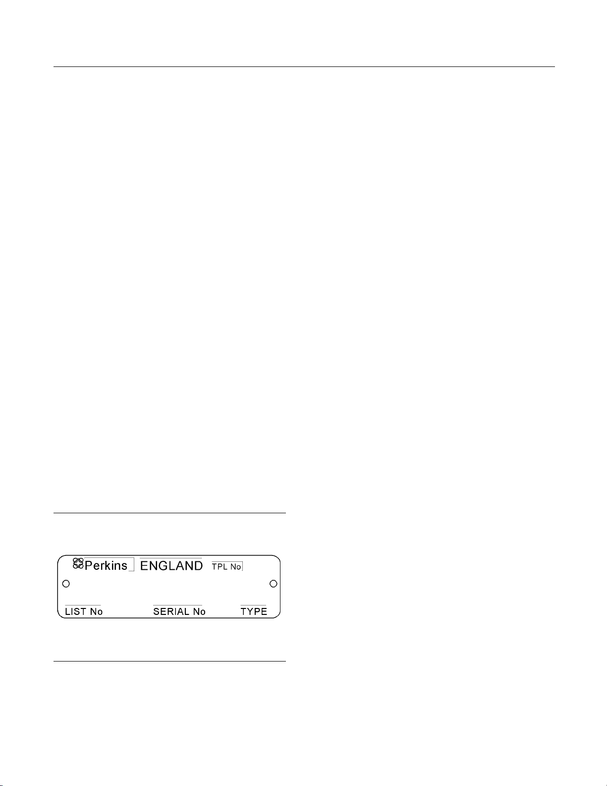
i02157258
Serial Number Plate
g01094203
Illustra
tion 23
Typical serial number plate
The Serial Number Plate is located above the fuel
injection pump on the right side of the cylinder block.
The following i
nformation is stamped on the Serial
Number Plate: Engine serial number, Model, and
Arrangement number.
i02164876
Reference Numbers
Information for the following items may be needed to
order parts. Locate the information for your engine.
Record the information in the appropriate space.
Make a copy of this list for a record. Keep the
information for future reference.
Record for Reference
Engine Model _ ______________________________________________
Engine Serial number _____________________________________
Engine Low Idle rpm ______________________________________
Engine Full Load rpm _____________________________________
Primary Fuel Filter _________________________________________
Water Separator Element ________________________________
Secondary Fuel Filter Element __________________________
Lubrication Oil Filter Element ___________________________
Auxiliary Oil Filter Element _______________________________
Total Lubrication System Capacity ______ _______________
Total Cooling System Capacity _________________________
Air Cleaner Element _______________________________________
Fan Drive Belt ______________________________________________
Alternator Belt ______________________________________________
This document has been printed from SPI². Not for Resale
24 SEBU8311-01
Product Information Section
Product Identification Information
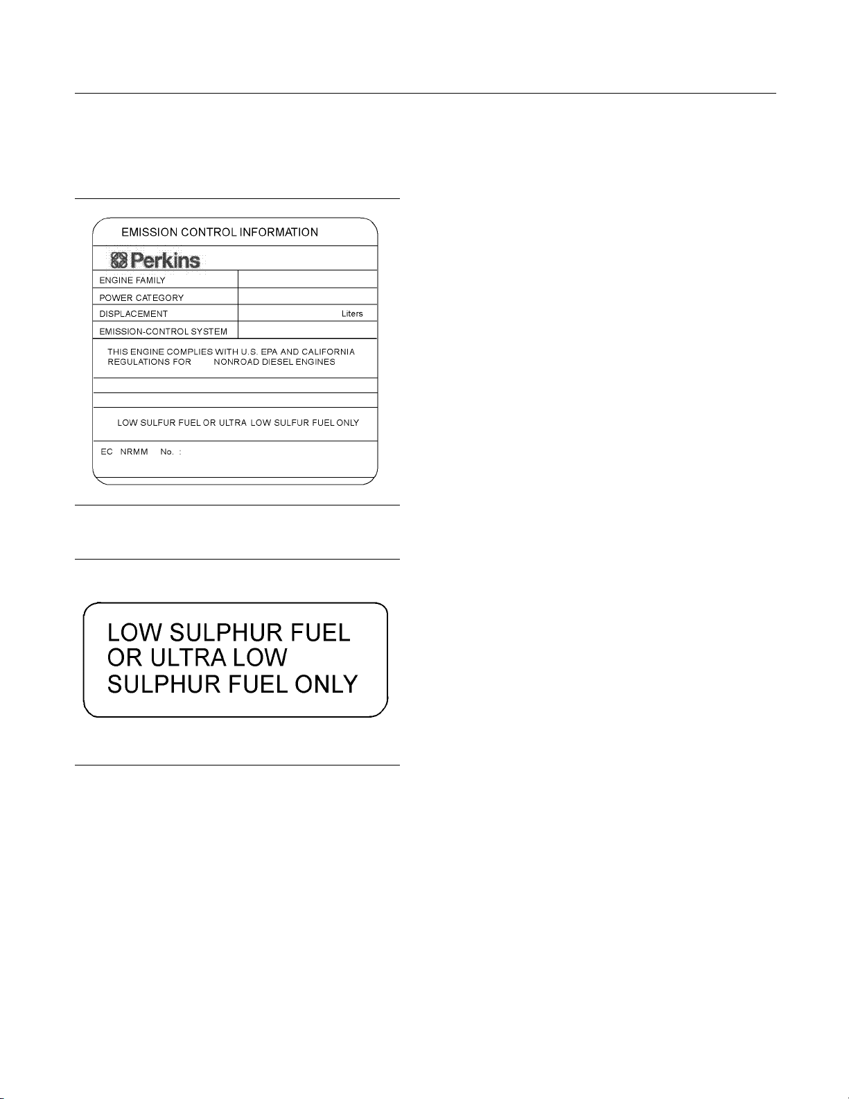
i02959144
Emissions Certification Film
g01478138
Illustration 24
Typical exam p le
g01476654
Illustration 25
Typical exam p le
Perkins Shibaura Engines Limited will supply the
fuel label with every engine. Refer to illustration
25. The equipment manufacturer must install the
label to the equipment. This is recommended by
Perkins Shibaura Engines Limited. The label must be
attached to the equipment near the fuel inlet. This
will comply with the EPA regulations. The equipment
manufacturer may install another fuel label. If another
fuel label is used, the equipment manufacturer must
send a drawing or a photo of the label to Perkins
Shibaura Engines Limited through the Perkins
Distributor. This will ensure compliance of the label.
This document has been printed from SPI². Not for Resale
SEBU8311-01 25
Operation Section
Lifting and Storage
Operation Section
Lifting and Storage
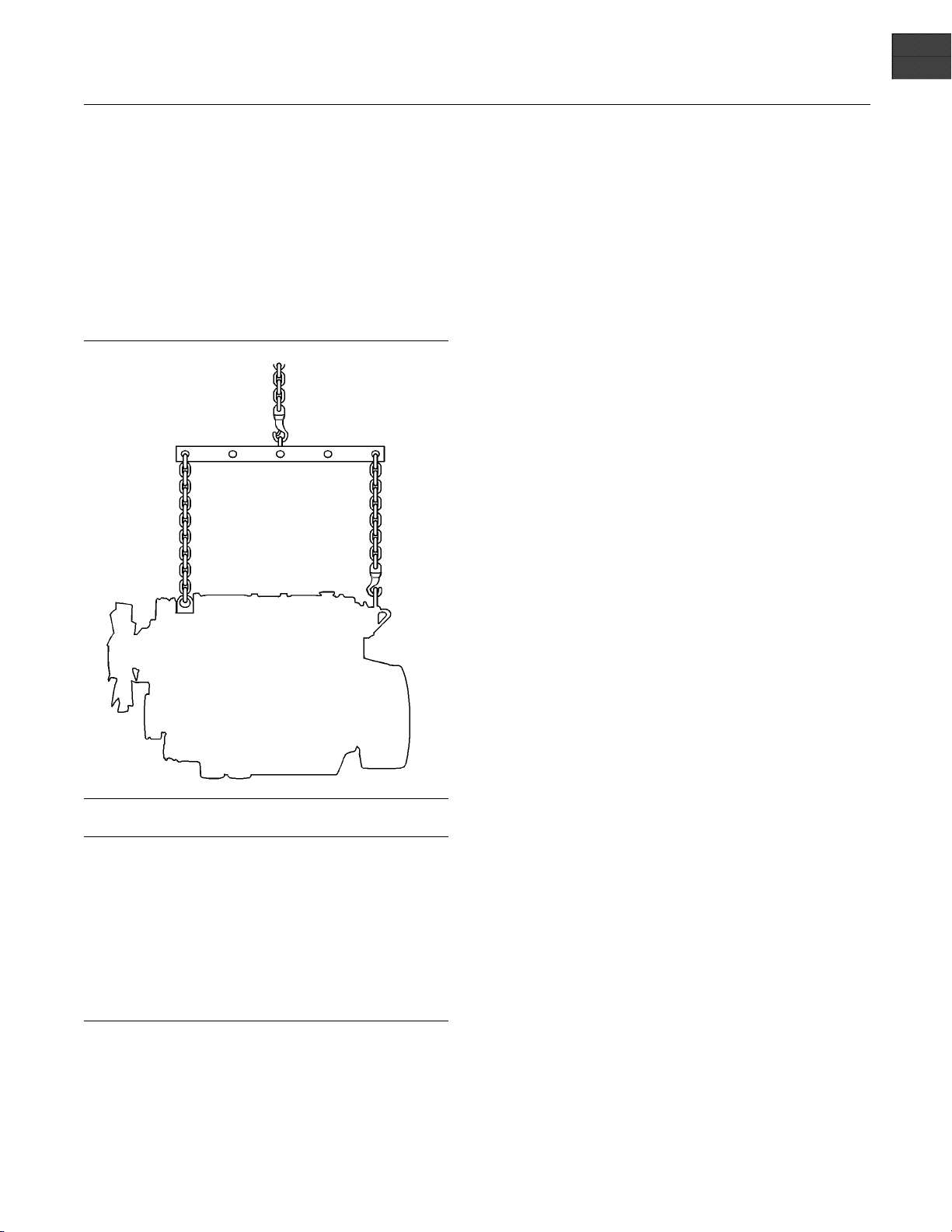
i02164186
Engine Lifting
g01097527
Illustration 26
NOTICE
Never bend the eyebolts and the brackets. Only load
the eyeb
olts and the brackets under tension. Remem-
ber that the capacity of an eyebolt is less as the angle
between the supporting members and the object be-
comes le
ss than 90 degrees.
When it is necessary to remove a component at an
angle, o
nly use a link bracket that is properly rated for
the weight.
Use a ho
ist to remove heavy components. Use
an adjustable lifting beam to lift the engine. All
supporting members (chains and cables) should be
parall
el to each other. The chains and cables should
be perpendicular to the top of the object that is being
lifted.
Some removals r
equire lifting the fixtures in order to
obtain correct balance and safety.
To r em ov e t h e e
ngine ONLY, use the lifting eyes that
are on the engine.
Lifting eyes a
re designed and installed for specific
engine arrangements. Alterations to the lifting eyes
and/or the engine make the lifting eyes and the lifting
fixtures obso
lete. If alterations are made, ensure
that correct lifting devices are provided. Consult
your Perkins dealer or your Perkins distributor for
information
regarding fixtures for correct engine
lifting.
i02593735
Engine Storage
If the engine will not be started for several weeks, the
lubricating oil will drain from the cylinder walls and
from the piston rings. Rust can form on the cylinder
walls. Rust on the cylinder walls will cause increased
engine wear and a reduction in engine service life.
Lubrication System
To help prevent excessive engine wear, use the
following guidelines:
Complete all of the lubrication recommendations that
are listed in this Operation and Maintenance Manual,
“Maintenance Interval Schedule” (Maintenance
Section).
If an engine is out of operation and if use of the engine
is not planned, special precautions should be made.
If the engine will be stored for more than one month,
a complete protection procedure is recommended.
Use the following guidelines :
•
Completely clean the outside of the engine.
•
Drain the fuel system completely and refill
thesystemwithpreservativefuel.1772204
POWERPART Lay-Up 1 can be mixed with
the normal fuel in order to change the fuel into
preservative fuel.
•
If preservative fuel is not available, the fuel system
can be filled with normal fuel. This fuel must be
discarded at the end of the storage period together
with the fuel filter elements.
•
Operate the engine until the engine reaches normal
operating temperature. Stop any leaks from fuel,
lubricating oil or air systems. Stop the engine and
drain the lubricating oil from the oil pan.
This document has been printed from SPI². Not for Resale
26 SEBU8311-01
Operation Section
Lifting and Storage
•
Renew the canis
ter(s) of the lubricating oil filter.
•
FilltheoilpantotheFullMarkontheengineoil
level gauge wi
th new, clean lubricating oil. Add
1762811 POWERPART Lay-Up 2 to the oil in
order to protect the engine against corrosion. If
1762811 POWE
RPART Lay-Up 2 is not available,
use a preservative of the correct specification
instead of the lubricating oil. If a preservative is
used, this mu
st be drained completely at the end of
the storage period and the oil pan must be refilled
to the correct level with normal lubricating oil.
Cooling System
To help prevent excessive engine wear, use the
following guidelines:
NOTICE
Do not drain the coolant while the engine is still hot and
the system is under pressure because dangerous hot
coolant can
be discharged.
If freezing temperatures are expected, check the
cooling sys
tem for adequate protection against
freezing. Refer to this Operation and Maintenance
Manual, “Fluid Recommendations” (Maintenance
Section).
NOTICE
To prevent frost damage, ensure that all the coolant is
removed fr
om the engine. This is important if the sys-
tem is drained after it has been flushed with water, or if
an antifreeze solution too weak to protect the system
from frost
has been used.
g01298045
Illustration 27
Typical exam p le
1. Ensure that the
vehicle is on level ground.
2. Remove the filler cap of the cooling system.
3. Remove the drain plug (1) from the side of the
cylinder block in order to drain the engine. Ensure
that the drain
hole is not restricted.
4. Open the tap or remove the drain plug at the
bottom of the r
adiator in order to drain the radiator.
If the radiator does not have a tap or a drain plug,
disconnect the hose at the bottom of the radiator.
5. Flushthecoolingsystemwithcleanwater.
6. Fit the drain
plugs and the filler cap. Close the tap
or connect the radiator hose.
7. Fill the cool
ing system with an approved antifreeze
mixture because this gives protection against
corrosion.
Note: Certain corrosion inhibitors could cause
damage to some engine components. Contact the
Service Dep
artment of Perkins for advice.
8. Operate the engine for a short period in order to
circulate t
he lubricating oil and the coolant in the
engine.
9. Disconnect
the battery. Put the battery into safe
storage in a fully charged condition. Before the
battery is put into storage, protect the terminals
against co
rrosion. 1734115 POWERPART
Lay-Up 3 can be used on the terminals.
10. Clean the c
rankcase breather if one is installed.
Seal the end of the pipe.
11. Remove the
fuel injectors and spray 1762811
POWERPART Lay-Up 2 for one or two seconds
into each cylinder bore with the piston at BDC.
12. Slowly rotate the crankshaft for one complete
revolution and then replace the fuel injectors.
Induction System
•
Remove the air filter assembly. If necessary,
remove the pipes that are installed between
the air fil
ter assembly and the turbocharger.
Spray 1762811 POWERPART Lay-Up 2 into the
turbocharger. The duration of the spray is printed
on the co
ntainer. Seal the turbocharger with
waterproof tape.
This document has been printed from SPI². Not for Resale

SEBU8311-01 27
Operation Section
Lifting and Storage
Exhaust System
•
Remove the exhaust pipe. Spray 1762811
POWERPART Lay-Up 2 into the turbocharger. The
duration of the spray is printed on the container.
Seal the turbocharger with waterproof tape.
General Items
•
If the lubricating oil filler is installed on the valve
mechanism cover, remove the filler cap. If the
lubricating oil filler cap is not installed on the valve
mechanism cover, remove the valve mechanism
cover. Spray 1762811 POWERPART Lay-Up 2
around the rocker shaft assembly. Replace the
filler cap or the valve mechanism cover.
•
Seal the vent of the fuel tank or the fuel filler cap
with waterproof tape.
•
Remove the alternator drive belts and put the drive
belts into storage.
•
In order to prevent corrosion, spray the engine with
1734115 POWERPART Lay-Up 3. Do not spray
the area inside the alternator.
When the engine protection has been completed in
accordance with these instructions, this ensures that
no corrosion will occur. Perkins are not responsible
for damage which may occur when an engine is in
storage after a period in service.
Your Perkins dealer or your Perkins distributor can
assist in preparing the engine for extended storage
periods.
This document has been printed from SPI². Not for Resale
28 SEBU8311-01
Operation Section
Gauges and Indicators
Gauges and Ind icators
i02216960
Gauges and Indicators
Your engine m
ay not have the same gauges or all of
the gauges that are described. For more information
about the gauge package, see the OEM information.
Gauges provide indications of engine performance.
Ensure that the gauges are in good working order.
Determine th
e normal operating range by observing
the gauges over a period of time.
Noticeable c
hanges in gauge readings indicate
potential gauge or engine problems. Problems may
also be indicated by gauge readings that change
even if the r
eadings are within specifications.
Determine and correct the cause of any significant
change in the readings. Consult your Perkins dealer
or your Per
kins distributor for assistance.
NOTICE
If no oil pressure is indicated, STOP the engine. If
maximum co
olant temperature is exceeded, STOP
the engine. Engine damage can result.
Engine Oil
Pressure – The oil pressure
should be greatest after a cold engine is
started. The typical engine oil pressure with
SAE10W30
is 207 to 413 kPa (30 to 60 psi) at rated
rpm.
A lower oil pressure is normal at low idle. If the load
is stable
and the gauge reading changes, perform
the following procedure:
1. Remove th
e load.
2. Reduce engine speed to low idle.
3. Check and maintain the oil level.
Jacket Wa
ter Coolant Temperature –
Typical temperature range is 71 to 96°C
(160 to 205°F). The maximum allowable
tempera
ture with t he pressurized cooling system
at 90 kPa (13 psi) is 110°C (230°F). Higher
temperatures may occur under certain conditions.
The wate
r temperature reading may vary according
to load. The reading should never exceed the boiling
point for the pressurized system that is being used.
If the en
gine is operating above the normal range
and steam becomes apparent, perform the following
procedure:
1. Reduce the load
and the engine rpm.
2. Inspect the cooling system for leaks.
3. Determine if the engine must be shut down
immediately or if the engine can be cooled by
reducing the l
oad.
Tachometer – This gauge indicates engine
speed (rpm). W
hen the throttle control lever
ismovedtothefullthrottlepositionwithout
load, the engine is running at high idle. The engine is
running at th
efullloadrpmwhenthethrottlecontrol
lever is at the full throttle position with maximum
rated load.
NOTICE
To help prevent engine damage, never exceed the
high idle rpm. Overspeeding can result in serious
damage to the engine. The engine can be operated
at high idle without damage, but should never be
allowedtoexceedhighidlerpm.
Ammeter – This gauge indicates the
amount of charge or discharge in the
battery charging circuit. Operation of the
indicator should be to the right side of “0” (zero).
Fuel Level – This gauge indicates the fuel
level in the fuel tank. The fuel level gauge
operates when the “START/ST OP” switch
is in the “ON” position.
Service Hour Meter – The gauge indicates
operating time of the engine.
This document has been printed from SPI². Not for Resale
SEBU8311-01 29
Operation Section
Features and Controls
Features and Controls
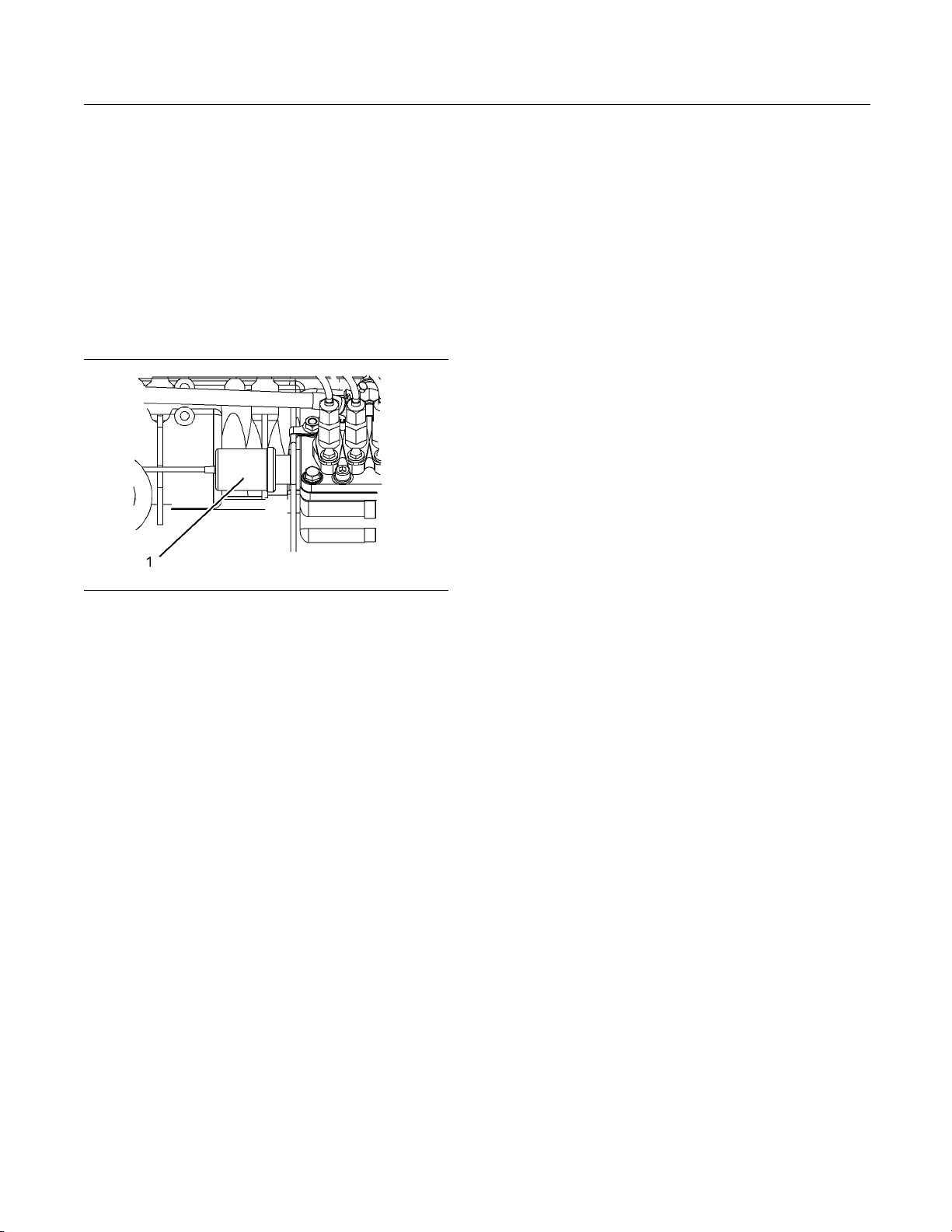
i02593769
Fuel Shutoff
The fuel shutoff solenoid is located on the fuel
injection pump. When the fuel shutoff solenoid is
activated, the solenoid moves the fuel rack to the
“OFF” position.
g01305771
Illustration 28
(1) Fuel shutoff solenoid
If an electronically controlled governor has been
installed the governor operates the fuel rack in order
to stop the engine.
This document has been printed from SPI². Not for Resale
 Loading...