


SEBU9064
June 2013
Operation and
Maintenance
Manual
402F-05, 403F-07, 403F-11, and 403F-15 Industrial Engines
EG (Engine)
EH (Engine)
EJ (Engine)
EK (Engine)

Important Safety Information
Most accidents that involve product operation, maintenance and repair are caused by failure to observe basic safety rules or precautions. An accident can often be avoided by recognizing potentially hazardous situations before an accident occurs. A person must be alert to potential hazards. This person should also have the necessary training, skills and tools to perform these functions properly.
Improper operation, lubrication, maintenance or repair of this product can be dangerous and could result in injury or death.
Do not operate or perform any lubrication, maintenance or repair on this product, until you have read and understood the operation, lubrication, maintenance and repair information.
Safety precautions and warnings are provided in this manual and on the product. If these hazard warnings are not heeded, bodily injury or death could occur to you or to other persons.
The hazards are identified by the “Safety Alert Symbol” and followed by a “Signal Word” such as “DANGER”, “WARNING” or “CAUTION”. The Safety Alert “WARNING” label is shown below.
The meaning of this safety alert symbol is as follows:
Attention! Become Alert! Your Safety is Involved.
The message that appears under the warning explains the hazard and can be either written or pictorially presented.
Operations that may cause product damage are identified by “NOTICE” labels on the product and in this publication.
Perkins cannot anticipate every possible circumstance that might involve a potential hazard. The warnings in this publication and on the product are, therefore, not all inclusive. If a tool, procedure, work method or operating technique that is not specifically recommended by Perkins is used,
you must satisfy yourself that it is safe for you and for others. You should also ensure that the product will not be damaged or be made unsafe by the operation, lubrication, maintenance or repair procedures that you choose.
The information, specifications, and illustrations in this publication are on the basis of information that was available at the time that the publication was written. The specifications, torques, pressures, measurements, adjustments, illustrations, and other items can change at any time. These changes can affect the service that is given to the product. Obtain the complete and most current information before you start any job. Perkins dealers or Perkins distributors have the most current information available.
When replacement parts are required for this product Perkins recommends using Perkins replacement parts.
Failure to heed this warning can lead to premature failures, product damage, personal injury or death.

SEBU9064
Table of Contents |
|
Foreword.............................. ............................. |
4 |
Safety Section |
|
Safety Messages....................... ....................... |
5 |
General Hazard Information............... .............. |
6 |
Burn Prevention........................ ........................ |
7 |
Fire Prevention and Explosion Prevention .... ... |
8 |
Crushing Prevention and Cutting Prevention .. |
. 9 |
Before Starting Engine ................. .................. |
10 |
Engine Starting........................ ....................... |
10 |
Engine Stopping ....................... ....................... |
11 |
Electrical System...................... ....................... |
11 |
Product Information Section |
|
General Information.................... .................... |
12 |
Product Identification Information.......... ......... |
18 |
Operation Section |
|
Lifting and Storage..................... ..................... |
20 |
Features and Controls.................. .................. |
22 |
Engine Diagnostics..................... .................... |
26 |
Engine Starting........................ ....................... |
29 |
Engine Operation...................... ...................... |
31 |
Cold Weather Operation................. ................ |
32 |
Engine Stopping ....................... ...................... |
36 |
Maintenance Section |
|
|
3 |
|
Table of Contents |
Maintenance Interval Schedule |
........... ........... 54 |
Warranty Section |
|
Warranty Information................... |
................... 82 |
Reference Information Section |
|
Reference Materials ........................................ |
83 |
Index Section |
|
Index................................ ............................... |
84 |
Refill Capacities....................... ....................... |
37 |
Maintenance Recommendations.......... .......... |
51 |

4
Foreword
Foreword
Literature Information
This manual contains safety, operation instructions,
lubrication and maintenance information. This manual should be stored in or near the engine area in a
literature holder or literature storage area. Read, study and keep it with the literature and engine information.
English is the primary language for all Perkins publications. The English used facilitates translation and consistency.
Some photographs or illustrations in this manual show details or attachments that may be different from your engine. Guards and covers may have been removed for illustrative purposes. Continuing improvement and advancement of product design may have caused changes to your engine which are not included in this manual. Whenever a question arises regarding your engine, or this manual, please consult with your Perkins dealer or your Perkins distributor for the latest available information.
Safety
This safety section lists basic safety precautions. In addition, this section identifies hazardous, warning
situations. Read and understand the basic precautions listed in the safety section before
operating or performing lubrication, maintenance and repair on this product.
Operation
Operating techniques outlined in this manual are basic. They assist with developing the skills and techniques required to operate the engine more efficiently and economically. Skill and techniques develop as the operator gains knowledge of the engine and its capabilities.
The operation section is a reference for operators. Photographs and illustrations guide the operator through procedures of inspecting, starting, operating and stopping the engine. This section also includes a discussion of electronic diagnostic information.
Maintenance
The maintenance section is a guide to engine care. The illustrated, step-by-step instructions are grouped by service hours and/or calendar time maintenance
intervals. Items in the maintenance schedule are referenced to detailed instructions that follow.
SEBU9064
Recommended service should be performed at the appropriate intervals as indicated in the Maintenance Interval Schedule. The actual operating environment of the engine also governs the Maintenance Interval Schedule. Therefore, under extremely severe, dusty, wet or freezing cold operating conditions, more frequent lubrication and maintenance than is specified in the Maintenance Interval Schedule may be necessary.
The maintenance schedule items are organized for a preventive maintenance management program. If the preventive maintenance program is followed, a periodic tune-up is not required. The implementation of a preventive maintenance management program should minimize operating costs through cost avoidances resulting from reductions in unscheduled downtime and failures.
Maintenance Intervals
Perform maintenance on items at multiples of the original requirement. We recommend that the maintenance schedules be reproduced and displayed near the engine as a convenient reminder. We also
recommend that a maintenance record be maintained as part of the engine's permanent record.
Your authorized Perkins dealer or your Perkins distributor can assist you in adjusting your maintenance schedule to meet the needs of your operating environment.
Overhaul
Major engine overhaul details are not covered in the Operation and Maintenance Manual except for the
interval and the maintenance items in that interval. Major repairs should only be carried out by Perkins
authorized personnel. Your Perkins dealer or your Perkins distributor offers a variety of options regarding overhaul programs. If you experience a major engine failure, there are also numerous after failure overhaul options available. Consult with your Perkins dealer or your Perkins distributor for information regarding these options.
California Proposition 65 Warning
Diesel engine exhaust and some of its constituents
are known to the State of California to cause cancer, birth defects, and other reproductive harm. Battery
posts, terminals and related accessories contain lead and lead compounds. Wash hands after handling.

SEBU9064
Safety Section
i05333233
Safety Messages
There may be several specific warning signs on your engine. The exact location and a description of the warning signs are reviewed in this section. Become familiar with all warning signs.
Ensure that all of the warning signs are legible. Clean the warning signs or replace the warning signs if the
words cannot be read or if the illustrations are not visible. Use a cloth, water, and soap to clean the
warning signs. Do not use solvents, gasoline, or other harsh chemicals. Solvents, gasoline, or harsh
chemicals could loosen the adhesive that secures the warning signs.
Replace any warning sign that is damaged or missing. If a warning sign is attached to a part of the engine that is replaced, install a new warning sign on the replacement part. Your Perkins dealer or your distributor can provide new warning signs.
(A) Universal Warning
Do not operate or work on this equipment unless you have read and understand the instructions and warnings in the Operation and Maintenance Manuals. Failure to follow the instructions or heed the warnings could result in serious injury or death.
Illustration 1 |
g01154807 |
Typical example
Warning label (A) is installed in different locations. The location will change according to the physical size of the engine.
5
Safety Section
Safety Messages
6 |
SEBU9064 |
Safety Section
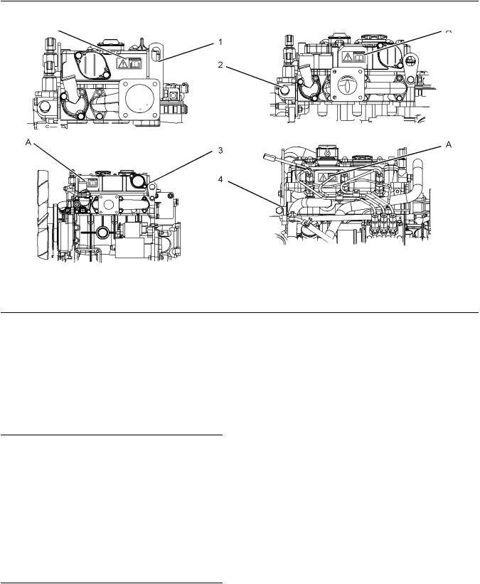
General Hazard Information
Illustration 2
Typical examples
(A) Location of warning label |
(2) |
403F-07 |
(1) 402F-05 |
(3) |
403F-11 |
i02328435
General Hazard Information
Illustration 3 |
g00104545 |
Attach a “Do Not Operate” warning tag or a similar warning tag to the start switch or to the controls before you service the equipment or before you repair the equipment.
g03378379
(4) 403F-15
Illustration 4 |
g00702020 |
Wear a hard hat, protective glasses, and other protective equipment, as required.
Do not wear loose clothing or jewelry that can snag on controls or on other parts of the engine.
Make sure that all protective guards and all covers are secured in place on the engine.
Keep the engine free from foreign material. Remove
debris, oil, tools, and other items from the deck, from walkways, and from steps.

SEBU9064
Never put maintenance fluids into glass containers. Drain all liquids into a suitable container.
Obey all local regulations for the disposal of liquids.
Use all cleaning solutions with care.
Report all necessary repairs.
Do not allow unauthorized personnel on the equipment.
Ensure that the power supply is disconnected before you work on the bus bar or the glow plugs.
Perform maintenance on the engine with the equipment in the servicing position. Refer to the OEM information for the procedure for placing the equipment in the servicing position.
Pressure Air and Water
Pressurized air and/or water can cause debris and/or hot water to be blown out. This could result in personal injury.
The direct application of pressurized air or pressurized water to the body could result in personal injury.
When pressurized air and/or water is used for cleaning, wear protective clothing, protective shoes, and eye protection. Eye protection includes goggles or a protective face shield.
The maximum air pressure for cleaning purposes must be below 205 kPa (30 psi). The maximum water pressure for cleaning purposes must be below
275 kPa (40 psi).
Fluid Penetration
Pressure can be trapped in the hydraulic circuit long after the engine has been stopped. The pressure can cause hydraulic fluid or items such as pipe plugs to escape rapidly if the pressure is not relieved correctly.
Do not remove any hydraulic components or parts until pressure has been relieved or personal injury may occur. Do not disassemble any hydraulic components or parts until pressure has been relieved or personal injury may occur. Refer to the OEM information for any procedures that are required to relieve the hydraulic pressure.
7
Safety Section
Burn Prevention
Illustration 5 |
g00687600 |
Always use a board or cardboard when you check for a leak. Leaking fluid that is under pressure can penetrate body tissue. Fluid penetration can cause serious injury and possible death. A pin hole leak can cause severe injury. If fluid is injected into your skin, you must get treatment immediately. Seek treatment from a doctor that is familiar with this type of injury.
Containing Fluid Spillage
Care must be taken in order to ensure that fluids are contained during performance of inspection,
maintenance, testing, adjusting and repair of the engine. Make provision to collect the fluid with a suitable container before any compartment is opened or before any component is disassembled.
•Only use the tools that are suitable for collecting fluids and equipment that is suitable for collecting fluids.
•Only use the tools that are suitable for containing fluids and equipment that is suitable for containing fluids.
Obey all local regulations for the disposal of liquids.
i02143195
Burn Prevention
Do not touch any part of an operating engine. Allow the engine to cool before any maintenance is performed on the engine. Relieve all pressure in the air system, in the hydraulic system, in the lubrication system, in the fuel system, or in the cooling system before any lines, fittings or related items are disconnected.
Coolant
When the engine is at operating temperature, the engine coolant is hot. The coolant is also under pressure. The radiator and all lines to the heaters or to the engine contain hot coolant.

8 |
SEBU9064 |
Safety Section
Fire Prevention and Explosion Prevention
Any contact with hot coolant or with steam can cause severe burns. Allow cooling system components to cool before the cooling system is drained.
Check the coolant level after the engine has stopped and the engine has been allowed to cool.
Ensure that the filler cap is cool before removing the filler cap. The filler cap must be cool enough to touch with a bare hand. Remove the filler cap slowly in order to relieve pressure.
Cooling system conditioner contains alkali. Alkali can cause personal injury. Do not allow alkali to contact the skin, the eyes, or the mouth.
Oils
Hot oil and hot lubricating components can cause personal injury. Do not allow hot oil to contact the skin. Also, do not allow hot components to contact the skin.
Batteries
Electrolyte is an acid. Electrolyte can cause personal injury. Do not allow electrolyte to contact the skin or the eyes. Always wear protective glasses for servicing batteries. Wash hands after touching the batteries and connectors. Use of gloves is recommended.
i02813488
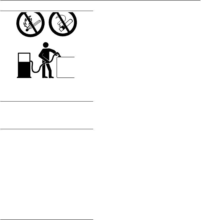
Fire Prevention and Explosion
Prevention
Illustration 6 |
g00704000 |
All fuels, most lubricants, and some coolant mixtures are flammable.
Flammable fluids that are leaking or spilled onto hot surfaces or onto electrical components can cause a fire. Fire may cause personal injury and property damage.
A flash fire may result if the covers for the engine
crankcase are removed within fifteen minutes after an emergency shutdown.
Determine whether the engine will be operated in an environment that allows combustible gases to be drawn into the air inlet system. These gases could cause the engine to overspeed. Personal injury, property damage, or engine damage could result.
If the application involves the presence of combustible gases, consult your Perkins dealer and/ or your Perkins distributor for additional information about suitable protection devices.
Remove all flammable combustible materials or conductive materials such as fuel, oil, and debris from the engine. Do not allow any flammable combustible
materials or conductive materials to accumulate on the engine.
Store fuels and lubricants in correctly marked containers away from unauthorized persons. Store oily rags and any flammable materials in protective
containers. Do not smoke in areas that are used for storing flammable materials.
Do not expose the engine to any flame.
Exhaust shields (if equipped) protect hot exhaust components from oil or fuel spray in case of a line, a
tube, or a seal failure. Exhaust shields must be installed correctly.
Do not weld on lines or tanks that contain flammable fluids. Do not flame cut lines or tanks that contain flammable fluid. Clean any such lines or tanks
thoroughly with a nonflammable solvent prior to welding or flame cutting.
Wiring must be kept in good condition. All electrical wires must be correctly routed and securely attached. Check all electrical wires daily. Repair any wires that are loose or frayed before you operate the engine. Clean all electrical connections and tighten all electrical connections.
Eliminate all wiring that is unattached or unnecessary. Do not use any wires or cables that are smaller than the recommended gauge. Do not bypass any fuses and/or circuit breakers.
Arcing or sparking could cause a fire. Secure connections, recommended wiring, and correctly maintained battery cables will help to prevent arcing or sparking.
Inspect all lines and hoses for wear or for deterioration. The hoses must be correctly routed. The lines and hoses must have adequate support and secure clamps. Tighten all connections to the recommended torque. Leaks can cause fires.
Oil filters and fuel filters must be correctly installed. The filter housings must be tightened to the correct torque.
SEBU9064 |
9 |
Safety Section
Crushing Prevention and Cutting Prevention
Illustration 7 |
g00704059 |
Use caution when you are refueling an engine. Do not smoke while you are refueling an engine. Do not refuel an engine near open flames or sparks. Always stop the engine before refueling.
Illustration 8 |
g00704135 |
Gases from a battery can explode. Keep any open flames or sparks away from the top of a battery. Do not smoke in battery charging areas.
Never check the battery charge by placing a metal object across the terminal posts. Use a voltmeter or a hydrometer.
Incorrect jumper cable connections can cause an explosion that can result in injury. Refer to the Operation Section of this manual for specific instructions.
Do not charge a frozen battery. This may cause an explosion.
The batteries must be kept clean. The covers (if equipped) must be kept on the cells. Use the recommended cables, connections, and battery box covers when the engine is operated.
Fire Extinguisher
Make sure that a fire extinguisher is available. Be familiar with the operation of the fire extinguisher. Inspect the fire extinguisher and service the fire extinguisher regularly. Obey the recommendations on the instruction plate.
Lines, Tubes and Hoses
Do not bend high pressure lines. Do not strike high pressure lines. Do not install any lines that are bent or damaged. Do not clip any other items to the high pressure lines.
Repair any lines that are loose or damaged. Leaks can cause fires. Consult your Perkins dealer or your Perkins distributor for repair or for replacement parts.
Check lines, tubes and hoses carefully. Do not use your bare hand to check for leaks. Use a board or cardboard to check for leaks. Tighten all connections to the recommended torque.
Replace the parts if any of the following conditions are present:
•End fittings are damaged or leaking.
•Outer coverings are chafed or cut.
•Wires are exposed.
•Outer coverings are ballooning.
•Flexible part of the hoses are kinked.
•Outer covers have embedded armoring.
•End fittings are displaced.
Make sure that all clamps, guards, and heat shields are installed correctly. During engine operation, this will help to prevent vibration, rubbing against other parts, and excessive heat.
i02143194
Crushing Prevention and
Cutting Prevention
Support the component correctly when work beneath the component is performed.

10
Safety Section
Before Starting Engine
Unless other maintenance instructions are provided, never attempt adjustments while the engine is running.
Stay clear of all rotating parts and of all moving parts. Leave the guards in place until maintenance is performed. After the maintenance is performed, reinstall the guards.
Keep objects away from moving fan blades. The fan blades will throw objects or cut objects.
When objects are struck, wear protective glasses in order to avoid injury to the eyes.
Chips or other debris may fly off objects when objects are struck. Before objects are struck, ensure that no one will be injured by flying debris.
i02813489
Before Starting Engine
Before the initial start-up of an engine that is new, serviced or repaired, make provision to shut the engine off, in order to stop an overspeed. This may be accomplished by shutting off the air and/or fuel supply to the engine.
Overspeed shutdown should occur automatically for engines that are controlled electronically. If automatic shutdown does not occur, press the emergency stop button in order to cut the fuel and/or air to the engine.
Inspect the engine for potential hazards.
Before starting the engine, ensure that no one is on, underneath, or close to the engine. Ensure that the area is free of personnel.
If equipped, ensure that the lighting system for the engine is suitable for the conditions. Ensure that all lights work correctly, if equipped.
All protective guards and all protective covers must be installed if the engine must be started in order to perform service procedures. To help prevent an accident that is caused by parts in rotation, work around the parts carefully.
Do not bypass the automatic shutoff circuits. Do not
disable the automatic shutoff circuits. The circuits are provided in order to help prevent personal injury. The
circuits are also provided in order to help prevent engine damage.
See the Service Manual for repairs and for adjustments.
SEBU9064
i02157354
Engine Starting
Do not use aerosol types of starting aids such as ether. Such use could result in an explosion and personal injury.
If a warning tag is attached to the engine start switch or to the controls, DO NOTstart the engine or move the controls. Consult with the person that attached the warning tag before the engine is started.
All protective guards and all protective covers must be installed if the engine must be started in order to perform service procedures. To help prevent an accident that is caused by parts in rotation, work around the parts carefully.
Start the engine from the operator's compartment or from the engine start switch.
Always start the engine according to the procedure that is described in the Operation and Maintenance Manual, “Engine Starting” topic in the Operation Section. Knowing the correct procedure will help to prevent major damage to the engine components. Knowing the procedure will also help to prevent personal injury.
To ensure that the jacket water heater (if equipped) and/or the lube oil heater (if equipped) is working correctly, check the water temperature gauge and the oil temperature gauge during the heater operation.
Engine exhaust contains products of combustion which can be harmful to your health. Always start the engine and operate the engine in a well ventilated area. If the engine is started in an enclosed area, vent the engine exhaust to the outside.
Note: The engine is equipped with an automatic device for cold starting for normal conditions of operation. If the engine will be operated in very cold conditions, then an extra cold starting aid may be required. Normally, the engine will be equipped with the correct type of starting aid for your region of operation.
The 400 Series engines are equipped with a glow plug starting aid in each individual cylinder that heats the intake air in order to improve starting.
SEBU9064
i02234873
Engine Stopping
Stop the engine according to the procedure in the Operation and Maintenance Manual, “Engine Stopping (Operation Section)” in order to avoid overheating of the engine and accelerated wear of the engine components.
Use the Emergency Stop Button (if equipped) ONLY in an emergency situation. Do not use the Emergency Stop Button for normal engine stopping. After an emergency stop, DO NOTstart the engine until the problem that caused the emergency stop has been corrected.
Stop the engine if an overspeed condition occurs during the initial start-up of a new engine or an engine that has been overhauled.
To stop an electronically controlled engine, cut the power to the engine and/or shutting off the air supply to the engine.
i02176668
Electrical System
Never disconnect any charging unit circuit or battery circuit cable from the battery when the charging unit is operating. A spark can cause the combustible gases that are produced by some batteries to ignite.
To help prevent sparks from igniting combustible gases that are produced by some batteries, the negative “−” jump start cable should be connected last from the external power source to the negative “−” terminal of the starting motor. If the starting motor is not equipped with a negative “−” terminal, connect the jump start cable to the engine block.
Check the electrical wires daily for wires that are loose or frayed. Tighten all loose electrical wires before the engine is started. Repair all frayed electrical wires before the engine is started. See the Operation and Maintenance Manual for specific starting instructions.
Grounding Practices
Correct grounding for the engine electrical system is necessary for optimum engine performance and reliability. Incorrect grounding will result in uncontrolled electrical circuit paths and in unreliable electrical circuit paths.
Uncontrolled electrical circuit paths can result in damage to main bearings, to crankshaft bearing journal surfaces, and to aluminum components.
11
Safety Section
Engine Stopping
Engines that are installed without engine-to-frame ground straps can be damaged by electrical discharge.
To ensure that the engine and the engine electrical systems function correctly, an engine-to-frame ground strap with a direct path to the battery must be used. This path may be provided by way of a direct engine ground to the frame.
All grounds should be tight and free of corrosion. The engine alternator must be grounded to the negative “-” battery terminal with a wire that is adequate to handle the full charging current of the alternator.

12 |
SEBU9064 |
Product Information Section |
|
Model View Illustrations |
|
Product Information |
General Information |
Section |
|
i05333703
Model View Illustrations
The 403F-15 Engine View
Illustration 9 |
|
|
g03378808 |
|
Typical example |
|
|
|
|
(1) |
Rear lifting eye |
(5) |
Low mounted oil filler cap |
(9) Oil filter |
(2) |
Top oil filler cap |
(6) |
Fuel injection pump |
(10) Electronically controlled actuator |
(3) |
Front lifting eye |
(7) |
Oil gauge (Dipstick) |
(11) Injector |
(4) Water pump |
(8) Oil drain plug |
|
||

SEBU9064 |
13 |
General Information
Model View Illustrations
Illustration 10 |
|
g03379877 |
(12) Air intake |
(15) Solenoid for starter |
(18) Fan belt |
(13) Coolant outlet |
(16) Starting motor |
(18) Coolant intake connection |
(14) Exhaust manifold |
(17) Alternator |
|
14 |
SEBU9064 |
General Information
Model View Illustrations
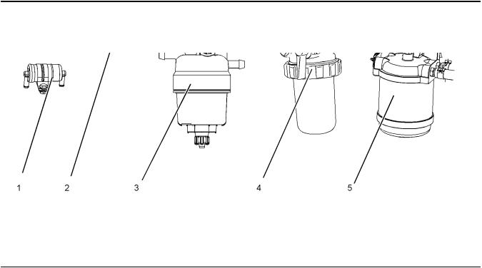
Fuel System Components
Illustration 11 |
|
g03379882 |
Typical examples |
|
|
(1) In-line fuel filter |
(3) Primary fuel filter |
(5) Secondary fuel filter |
(2) Electric fuel pump |
(4) Secondary fuel filter (element type) |
|
Note: The electric fuel pump is an option, engines may have a mechanical fuel lift pump installed.
SEBU9064 |
15 |
General Information
Product Description
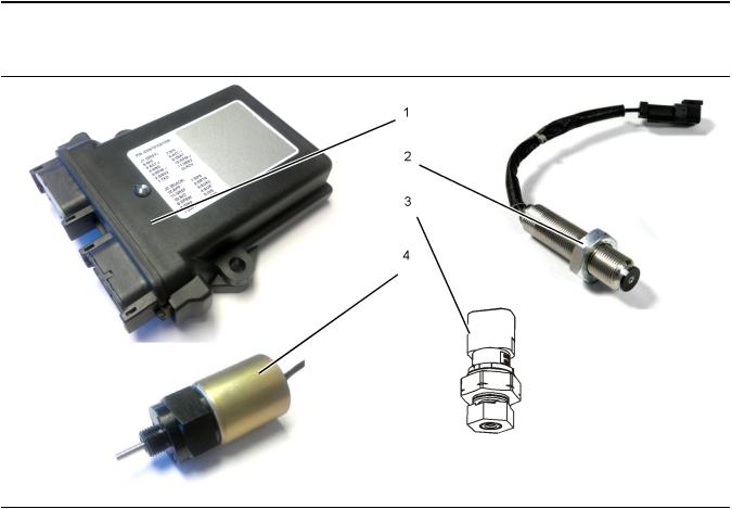
Components for Electronic Control
Illustration 12 |
|
g03379884 |
(1) Electronic Control Module (ECM) |
(3) Atmospheric Pressure Sensor |
(4) Actuator |
(2) Speed sensor |
(Barometric Pressure Sensor) |
|
Note: Due to individual applications the atmospheric pressure sensor (3) may appear different from the illustration.
i05333638
Engine Specifications
Note: The front end of the engine is opposite the flywheel end of the engine. The left and the right sides of the engine are determined from the flywheel end. The number 1 cylinder is the front cylinder.
Product Description
There are four Perkins engines in the 400F series that are below 19Kw power band. These engines are,
402F-05, 403F-07, 403F-11, and the 403F-15. These engines have the following characteristics:
•In-Line 2 cylinder (402F-05)
•In-Line 3 cylinder (403F-07, 403F-11, and the 403F-15)
•Naturally aspirated
•Fuel Limiter
•2 Valves in each cylinder
16 |
SEBU9064 |
General Information |
|
Product Description |
|
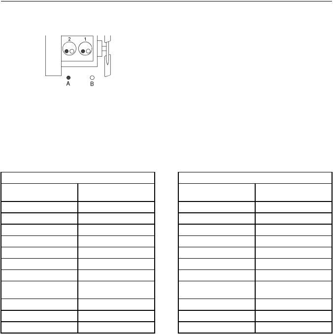
402F-05 Engine |
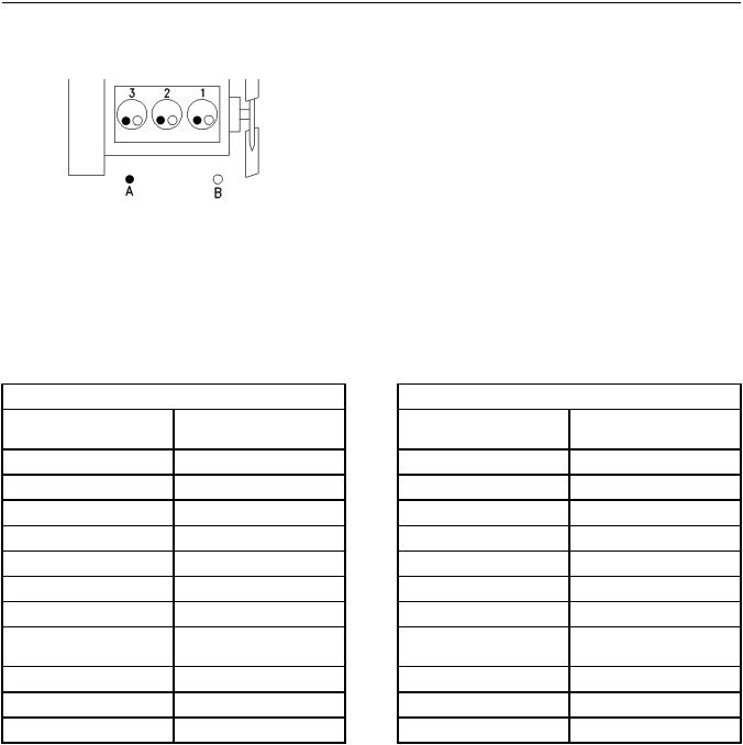
403F-07 Engine |
Illustration 13 |
g01108476 |
(A)Exhaust valves
(B)Inlet valves
Table 1
402F-05 Engine Specifications
Maximum Operating Speed (rpm)
Cylinders and Arrangement
Bore
Stroke
Displacement
Aspiration
Compression Ratio
Firing Order
Rotation that is viewed from the flywheel
Valve Lash Setting (Inlet)
Valve Lash Setting (Exhaust)
Injection
3600 rpm
In-Line 2 cylinder 67 mm (2.64 inch) 72 mm (2.83 inch) 0.507 L (30.939 in3) Naturally Aspirated
23.5:1 1-2
Counterclockwise
0.20 mm (0.008 inch)
0.20 mm (0.008 inch)
Indirect
Illustration 14 |
g00852304 |
(A)Exhaust valves
(B)Inlet valves
Table 2
403F-07 Engine Specifications
Maximum Operating Speed |
3600 rpm |
|
(rpm) |
||
|
||
Cylinders and Arrangement |
In-Line 3 cylinder |
|
Bore |
67 mm (2.64 inch) |
|
Stroke |
72 mm (2.83 inch) |
|
Displacement |
0.762 L (46.500 in3) |
|
Aspiration |
Naturally Aspirated |
|
Compression Ratio |
23.5:1 |
|
Firing Order |
1-2-3 |
|
Rotation that is viewed from the |
Counterclockwise |
|
flywheel |
||
|
||
Valve Lash Setting (Inlet) |
0.20 mm (0.008 inch) |
|
Valve Lash Setting (Exhaust) |
0.20 mm (0.008 inch) |
|
Injection |
Indirect |
SEBU9064 |
17 |
|
General Information |
|
Product Description |
403F-11 Engine |
403F-15 Engine |
Illustration 15 |
g00852304 |
(A)Exhaust valves
(B)Inlet valves
Table 3
403F-11 Engine Specifications
Maximum Operating Speed |
3600 rpm |
|
(rpm) |
||
|
||
Cylinders and Arrangement |
In-Line 3 cylinder |
|
Bore |
77 mm (3.03 inch) |
|
Stroke |
81 mm (3.19 inch) |
|
Displacement |
1.131 L (69.018 in3) |
|
Aspiration |
Naturally Aspirated |
|
Compression Ratio |
23:1 |
|
Firing Order |
1-2-3 |
|
Rotation that is viewed from the |
Counterclockwise |
|
flywheel |
||
|
||
Valve Lash Setting (Inlet) |
0.20 mm (0.008 inch) |
|
Valve Lash Setting (Exhaust) |
0.20 mm (0.008 inch) |
|
Injection |
Indirect |
Illustration 16 |
g00852304 |
(A)Exhaust valves
(B)Inlet valves
Table 4
403F-15 Engine Specifications
Maximum Operating Speed |
3000 rpm |
|
(rpm) |
||
|
||
Cylinders and Arrangement |
In-Line 3 cylinder |
|
Bore |
84 mm (3.31 inch) |
|
Stroke |
90 mm (3.54 inch) |
|
Displacement |
1.496 L (91.291 in3) |
|
Aspiration |
Naturally Aspirated |
|
Compression Ratio |
22.5:1 |
|
Firing Order |
1-2-3 |
|
Rotation that is viewed from the |
Counterclockwise |
|
flywheel |
||
|
||
Valve Lash Setting (Inlet) |
0.20 mm (0.008 inch) |
|
Valve Lash Setting (Exhaust) |
0.20 mm (0.008 inch) |
|
Injection |
Indirect |

18
Product Identification Information
Plate Locations and Film Locations
Product Identification
Information
i05333660
Plate Locations and Film
Locations
Perkins engines are identified by a serial number. This serial number is shown on a serial number plate. The plate is mounted above the fuel injection pump on the right-hand side of the engine block.
A typical example of an engine number is EK*****N000001X.
E |
Engine family |
K |
Type of engine |
***** |
The list number of the engine |
N |
Country of manufacture |
0 |
The first digit is a production code. |
00001 |
Engine Serial Number |
X |
Year of Manufacture |
Perkins dealers or Perkins distributors need all of these numbers in order to determine the components
that were included with the engine. This information permits accurate identification of replacement part numbers.
SEBU9064
i05333666
Emissions Certification Film
Illustration 17 |
g03378752 |
Typical example
i05335976
Reference Information
Information for the following items may be needed to order parts. Locate the information for your engine. Record the information in the appropriate space. Make a copy of this list for a record. Keep the information for future reference.
Record for Reference
Engine Model
Engine Serial Number
ECM Serial Number Engine Low Idle rpm
Engine Full Load rpm In-Line Fuel Filter
 Primary Fuel Filter
 Secondary Fuel Filter Element
Lubrication Oil Filter Element
Auxiliary Oil Filter Element

SEBU9064 |
19 |
Product Identification Information
Reference Information
Total Lubrication System Capacity
Total Cooling System Capacity
Air Cleaner Element
Alternator Belt
20
Operation Section
Product Lifting
Operation Section
Lifting and Storage
SEBU9064
Lifting eyes are designed and installed for specific engine arrangements. Alterations to the lifting eyes and/or the engine make the lifting eyes and the lifting
fixtures obsolete. If alterations are made, ensure that correct lifting devices are provided. Consult your
Perkins dealer or your Perkins distributor for information regarding fixtures for correct engine
i05335230 lifting.
Product Lifting
i05335259
Product Storage
Illustration 18 |
g03380038 |
Typical example
(1)Rear lifting eye
(2)Front lifting eye
NOTICE
Never bend the eyebolts and the brackets. Only load the eyebolts and the brackets under tension. Remember that the capacity of an eyebolt is less as the angle between the supporting members and the object becomes less than 90 degrees.
When it is necessary to remove a component at an angle, only use a link bracket that is properly rated for the weight.
Use a hoist to remove heavy components. Use an adjustable lifting beam to lift the engine. All supporting members (chains and cables) should be parallel to each other. The chains and cables should be perpendicular to the top of the object that is being lifted.
Some removals require lifting the fixtures in order to obtain correct balance and safety.
To remove the engine ONLY, use the lifting eyes that are on the engine.
Perkins are not responsible for damage which may occur when an engine is in storage after a period in service.
Your Perkins dealer or your Perkins distributor can assist in preparing the engine for extended storage periods.
Condition for Storage
The engine must be stored in a water proof building. The building must be kept at a constant temperature. Engines that are filled with Perkins ELC will have coolant protection to an ambient temperature of −36° C (−32.8° F). The engine must not be subjected to extreme variations in temperature and humidity.
Storage Period
An engine can be stored for up to 6 months provided all the recommendation are adhered to.
Storage Procedure
Keep a record of the procedure that has been completed on the engine.
Note: Do not store an engine that has biodiesel in the fuel system.
1.Ensure that the engine is clean and dry.
a.If the engine has been operated using biodiesel, the system must be drained and new filters installed. The fuel tank will require flushing.
b.Fill the fuel system with an ultra low sulfur fuel. For more information on acceptable fuels refer to this Operation and Maintenance Manual, “Fluid recommendations”. Operate the engine for 15 minutes in order to remove all biodiesel from the system.
2.Drain any water from the primary filter water separator. Ensure that the fuel tank is full.
SEBU9064
3.The engine oil will not need to be drained in order to store the engine. Provided the correct specification of engine oil is used the engine can be stored for up to 6 months. For the correct specification of engine oil refer to this Operation and Maintenance Manual, “Fluid recommendations”.
4.Remove the fan belt from the engine.
Sealed Coolant System
Ensure that the cooling system is filled with Perkins
ELC, or an antifreeze that meets ASTM D6210 specification.
Open Cooling System
Ensure that all cooling drain plugs have been opened. Allow the coolant to drain. Install the drain plugs. Place a vapor phase inhibitor into the system. The coolant system must be sealed once the vapor phase inhibitor has been introduced. The effect of the vapor phase inhibitor will be lost if the cooling system is open to the atmosphere.
For maintenance procedures ref to this Operation and Maintenance Manual.
Monthly Checks
The crankshaft must be rotated in order to change the spring loading on the valve train. Rotate the crankshaft more than 180 degrees. Visibly check for damage or corrosion to the engine.
Ensure that the engine is covered completely before storage. Log the procedure in the record for the engine.
21
Lifting and Storage
Product Storage

22
Features and Controls
Gauges and Indicators
Features and Controls
i05336041
Gauges and Indicators
Your engine may not have the same gauges or all of the gauges that are described. For more information about the gauge package, see the OEM information.
Gauges provide indications of engine performance. Ensure that the gauges are in good working order. Determine the normal operating range by observing the gauges over a period of time.
Noticeable changes in gauge readings indicate potential gauge or engine problems. Problems may also be indicated by gauge readings that change even if the readings are within specifications. Determine and correct the cause of any significant change in the readings. Consult your Perkins dealer or your Perkins distributor for assistance.
NOTICE
If no oil pressure is indicated, STOP the engine. If maximum coolant temperature is exceeded, STOP the engine. Engine damage can result.
Engine Oil Pressure – The oil pressure should be greatest after a cold engine is started. The typical engine oil pressure with SAE10W30 is 207 to 413 kPa (30 to 60 psi) at
rated rpm.
A lower oil pressure is normal at low idle. If the load is stable and the gauge reading changes, perform the following procedure:
1.Remove the load.
2.Reduce engine speed to low idle.
3.Check and maintain the oil level.
Jacket Water Coolant Temperature – Typical temperature range is 71 to 96°C (160 to 205°F). The maximum allowable
temperature with the pressurized cooling system at 90 kPa (13 psi) is 125° C (257° F). Higher temperatures may occur under certain conditions. The water temperature reading may vary according to load. The reading should never exceed the boiling point for the pressurized system that is being used.
If the engine is operating above the normal range and steam becomes apparent, perform the following procedure:
1. Reduce the load and the engine rpm.
SEBU9064
2.Inspect the cooling system for leaks.
3.Determine if the engine must be shut down immediately or if the engine can be cooled by reducing the load.
Tachometer – This gauge indicates engine speed (rpm). When the throttle controller is moved to the full throttle
position without load, the engine is running at high idle. The engine is running at the full load rpm when the throttle controller is at the full throttle position with maximum rated load.
NOTICE
To help prevent engine damage, never exceed the high idle rpm. Overspeeding can result in serious damage to the engine. The engine can be operated at high idle without damage, but should never be allowed to exceed high idle rpm.
Ammeter – This gauge indicates the amount of charge or discharge in the battery charging circuit. Operation of the
indicator should be to the right side of ““0”” (zero).
Fuel Level – This gauge indicates the fuel level in the fuel tank. The fuel level gauge operates when the ““START/
STOP”” switch is in the ““ON”” position.
Service Hour Meter – The gauge indicates operating time of the engine.
Indicators and Lamps
The following indicator lamps can be installed, for more information refer to the Original Equipment Manufacturer (OEM)
•Shutdown lamp
•Warning lamp
•Low-pressure oil lamp
A multi function lamp is installed on the electric control module.
i05336105
Monitoring System

SEBU9064
NOTICE
The Engine Monitoring System is not a guarantee against catastrophic failures. Programmed delays and derate schedules are designed to minimize false alarms and provide time for the operator to stop the engine.
The following parameters are monitored:
•Coolant temperature
•Oil pressure
•Engine speed
•Atmospheric pressure (Barometric pressure)
The coolant temperature, oil pressure, and the engine speed can trigger an engine shutdown.
•Atmospheric pressure (Barometric pressure) can trigger an engine de-rate.
The atmospheric pressure sensor (Barometric pressure sensor) can de-rate the engine. Operating the engine and increasing the altitude will de-rate the engine in accordance with emission regulations. The start of the de-rate will be determined by the flash file that is installed.
i05336156
Overspeed
•402F-05 3600 Revolutions Per Minute (RPM)
•403F-07 3600 RPM
• 403F-11 |
3600 RPM |
• 403F-15 3000 RPM
The overspeed is plus 700 RPM above the given speed for engines shown.
i05336173
Sensors and Electrical
Components
The following sensors or switches are installed on the
402F-05, 403F-07, 403F-11, and the 403F-15 engines:
23
Features and Controls
Overspeed
•Oil pressure sensor
•Coolant temperature sensor
•Atmospheric pressure sensor (Barometric pressure sensor)
•Speed sensor
•Throttle actuator
24 |
SEBU9064 |
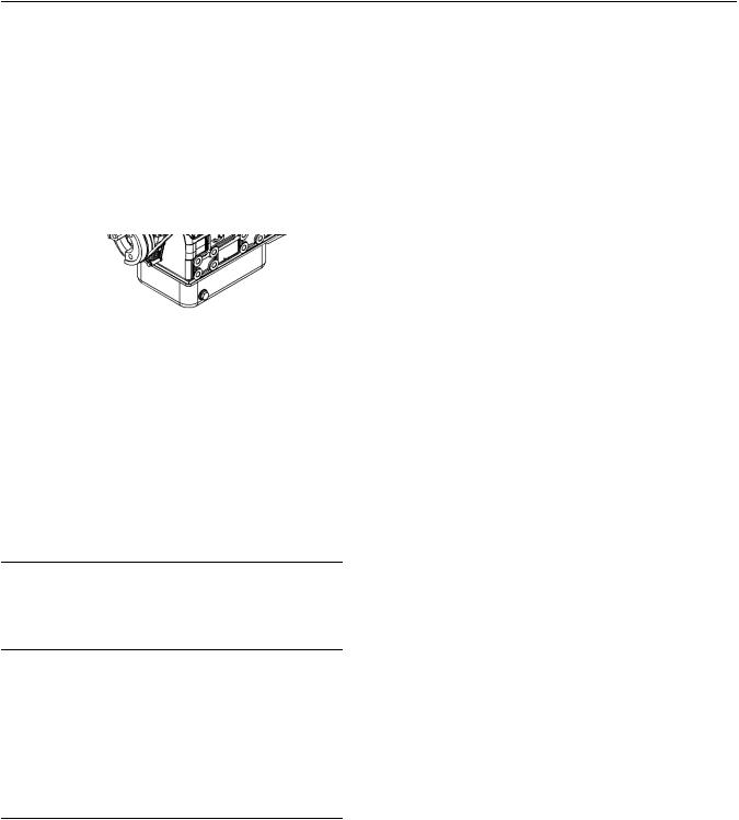
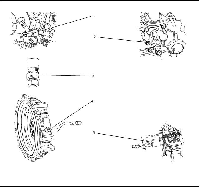
Features and Controls
Sensors and Electrical Components
Illustration 19 |
|
g03381125 |
Typical examples |
|
|
(1) Oil pressure sensor |
(3) Atmosphere pressure sensor (Barometric |
(4) Speed sensor |
(2) Coolant temperature sensor |
pressure sensor) |
(5) Throttle actuator |
Note: Due ti individual applications the atmosphere pressure sensor (3) may appear different from the illustration.
Electrical components install on the 402F-05, 403F07, 403F-11, and the 403F-15 engines:
•Alternator
•Starting motor
•Glow plugs
•Electronic control governor (Location will depend on the application)
•Electric fuel pump
SEBU9064 |
25 |
Features and Controls
Sensors and Electrical Components
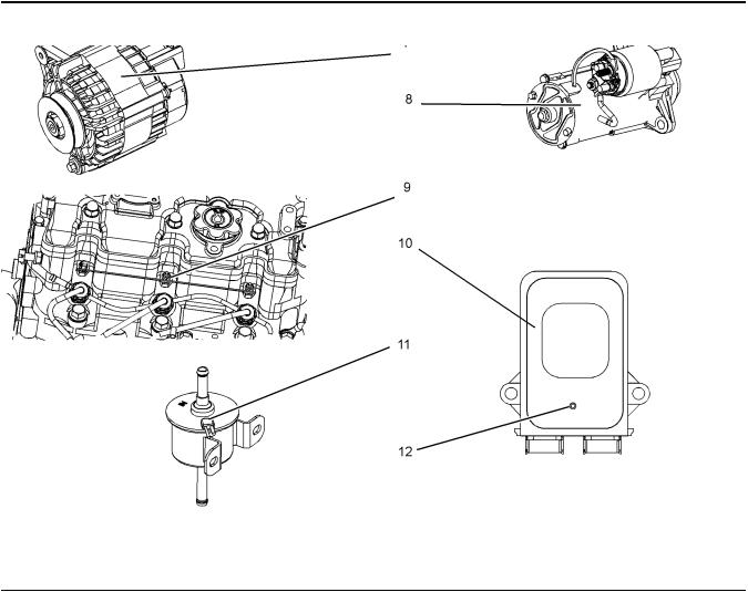
Illustration 20 |
|
g03381126 |
Typical examples |
|
|
(7) Alternator |
(9) Glow plugs |
(11) Fuel pump |
(8) Starting motor |
(10) Electronic control model (Controller) |
(12) Multi function lamp |
When the keyswitch is in the OFF position, the multi function lamp will not be illuminated. With the keyswitch in the ON position the multi function lamp will flash once. The flash will indicate that the system is powered and ready for operation.
The multi function lamp can be used as a diagnostic lamp. For information as a diagnostic lamp refer to this Operation and Maintenance Manual, “Diagnostic Lamp”.

26 |
SEBU9064 |
Engine Diagnostics
Self-Diagnostics
Engine Diagnostics
i05339798
Self-Diagnostics
The electronic engines can perform a self-diagnostics test. When the system detects an active problem, a diagnostic lamp is activated. This lamp is a multi function lamp that is located on the electronic control module. The lamp will flash a code that will give am
indication of the fault. For more information on the flash codes, refer to this Operation and Maintenance
Manual, “Diagnostic Flash Code Retrieval”.
i05339090
Diagnostic Lamp
The multi function lamp on the electronic control module can operate as a diagnostic lamp. The diagnostic function is used to indicate the existence
of an active fault. The active fault is transmitted as a flash code.
For information on flash codes refer to this Operation and Maintenance Manual, “Diagnostic Flash Code Retrieval”.
i05339103
Diagnostic Flash Code
Retrieval
The multi function lamp will flash a two-digit code in a given sequence in order to show the flash code diagnostic massage. By counting the number of flashes in a given sequence you can determine the flash code.
After the flash code as finished, the flash code sequence will continual to be repeated. If a second
flash code has been activated, then the system will repeat both codes in the given sequence.
Four short flashes will indicate a flash code of 04. Three long flashes of one second each followed by
one short flash will indicate a flash code of 31.
If there is more than one code to be indicated, the system will flash the first code then after a delay
interval the next code is flashed.

SEBU9064 |
27 |
Engine Diagnostics
Diagnostic Flash Code Retrieval
Table 5
Flash Codes with Key ON (Engine not in Operation)
Flash Code |
Description |
Engine status |
13 |
Oil pressure switch malfunction. |
Engine will start, but the engine will |
|
Disconnection of Oil pressure |
shut down after 180 seconds |
|
switch. |
|
|
Disconnection of Oil pressure |
|
|
harness. |
|
Operator Action
Check harness connection. If the fault remains contact your Perkins dealer or your Perkins distributor.
22 |
Pressure sensor malfunction. |
Engine will start, but the engine go |
|
Disconnection of Pressure sensor |
to limp home mode. |
connector.
Disconnection of Pressure sensor harness.
Check harness connection. If the fault remains contact your Perkins dealer or your Perkins distributor.
33 |
Actuator position sensor |
Engine will start, but the engine go |
|
malfunction. |
to limp home mode. |
Disconnection of Actuator position sensor connector.
Disconnection of Actuator position sensor harness.
Check harness connection. If the fault remains contact your Perkins dealer or your Perkins distributor.
04 |
Actuator drive malfunction. |
Engine will not start. |
Check harness connection. If the |
|
Disconnection of Speed sensor |
|
fault remains contact your Perkins |
|
connector. |
|
dealer or your Perkins distributor. |
|
Disconnection of Speed sensor |
|
|
|
harness. |
|
|
Table 6 |
|
|
|
|
Flash Codes During Engine Cranking |
|
|
Flash Code |
Description |
Engine status |
Operator Action |
13 |
Speed sensor malfunction. |
Engine will not start. |
Check harness connection. If the |
|
Disconnection of Speed sensor |
|
fault remains contact your Perkins |
|
connector. |
|
dealer or your Perkins distributor. |
|
Disconnection of Speed sensor |
|
|
|
harness. |
|
|
Table 7
Flash Codes with Engine in Operation
Flash Code |
Description |
Engine status |
31 |
Oil pressure decline. |
Engine will go to limp home mode |
|
Weak signal from oil pressure |
but the engine may shut down. |
|
switch. |
|
|
Short-circuiting. |
|
22 |
Pressure sensor malfunction. |
The engine will go into limp home |
|
Disconnection of Pressure sensor |
mode. |
|
connector. |
|
|
Disconnection of Pressure sensor |
|
|
harness. |
|
Operator Action
Check engine oil. (1)
Check harness connection. If the fault remains contact your Perkins dealer or your Perkins distributor.
Check harness connection. If the fault remains contact your Perkins dealer or your Perkins distributor.
33 |
Actuator position sensor |
The engine will go into limp home |
|
malfunction. |
mode. |
Disconnection of Actuator position sensor connector.
Disconnection of Actuator position sensor harness.
Check harness connection. If the fault remains contact your Perkins dealer or your Perkins distributor.
(continued)
 Loading...