


SEBU8609-01
January 2013
Operation and
Maintenance
Manual
403F-15T, 404F-22 and 404F-22T Industrial Engines
EL (Engine)
EN (Engine)
EP (Engine)

Important Safety Information
Most accidents that involve product operation, maintenance and repair are caused by failure to observe basic safety rules or precautions. An accident can often be avoided by recognizing potentially hazardous situations before an accident occurs. A person must be alert to potential hazards. This person should also have the necessary training, skills and tools to perform these functions properly.
Improper operation, lubrication, maintenance or repair of this product can be dangerous and could result in injury or death.
Do not operate or perform any lubrication, maintenance or repair on this product, until you have read and understood the operation, lubrication, maintenance and repair information.
Safety precautions and warnings are provided in this manual and on the product. If these hazard warnings are not heeded, bodily injury or death could occur to you or to other persons.
The hazards are identified by the “Safety Alert Symbol” and followed by a “Signal Word” such as “DANGER”, “WARNING” or “CAUTION”. The Safety Alert “WARNING” label is shown below.
The meaning of this safety alert symbol is as follows:
Attention! Become Alert! Your Safety is Involved.
The message that appears under the warning explains the hazard and can be either written or pictorially presented.
Operations that may cause product damage are identified by “NOTICE” labels on the product and in this publication.
Perkins cannot anticipate every possible circumstance that might involve a potential hazard. The warnings in this publication and on the product are, therefore, not all inclusive. If a tool, procedure, work method or operating technique that is not specifically recommended by Perkins is used,
you must satisfy yourself that it is safe for you and for others. You should also ensure that the product will not be damaged or be made unsafe by the operation, lubrication, maintenance or repair procedures that you choose.
The information, specifications, and illustrations in this publication are on the basis of information that was available at the time that the publication was written. The specifications, torques, pressures, measurements, adjustments, illustrations, and other items can change at any time. These changes can affect the service that is given to the product. Obtain the complete and most current information before you start any job. Perkins dealers or Perkins distributors have the most current information available.
When replacement parts are required for this product Perkins recommends using Perkins replacement parts.
Failure to heed this warning can lead to premature failures, product damage, personal injury or death.

SEBU8609
Table of Contents |
|
Foreword.............................. ............................. |
4 |
Safety Section |
|
Safety Messages....................... ....................... |
5 |
General Hazard Information............... .............. |
5 |
Burn Prevention........................ ........................ |
9 |
Fire Prevention and Explosion Prevention ... .. 10
Crushing Prevention and Cutting Prevention . .11
Mounting and Dismounting............... .............. |
12 |
Before Starting Engine ................. .................. |
12 |
Engine Starting........................ ....................... |
12 |
Engine Stopping ....................... ...................... |
13 |
Electrical System...................... ...................... |
13 |
Engine Electronics..................... ..................... |
14 |
Product Information Section |
|
General Information.................... .................... |
15 |
Product Identification Information.......... ......... |
26 |
Operation Section |
|
Lifting and Storage..................... ..................... |
28 |
Features and Controls.................. .................. |
30 |
Engine Diagnostics..................... .................... |
43 |
Engine Starting........................ ....................... |
45 |
Engine Operation...................... ...................... |
48 |
Cold Weather Operation................. ................ |
52 |
Engine Stopping ....................... ...................... |
56 |
|
3 |
|
Table of Contents |
Refill Capacities....................... ....................... |
57 |
Maintenance Recommendations.......... |
.......... 70 |
Maintenance Interval Schedule........... |
........... 73 |
Warranty Section |
|
Warranty Information................... |
................... 99 |
Reference Information Section |
|
Reference Materials .................. ................... |
103 |
Index Section |
|
Index............................... .............................. |
104 |
Maintenance Section

4
Foreword
Foreword
Literature Information
This manual contains safety, operation instructions,
lubrication and maintenance information. This manual should be stored in or near the engine area in a
literature holder or literature storage area. Read, study and keep it with the literature and engine information.
English is the primary language for all Perkins publications. The English used facilitates translation and consistency.
Some photographs or illustrations in this manual show details or attachments that may be different from your engine. Guards and covers may have been removed for illustrative purposes. Continuing improvement and advancement of product design may have caused changes to your engine which are not included in this manual. Whenever a question arises regarding your engine, or this manual, please consult with your Perkins dealer or your Perkins distributor for the latest available information.
Safety
This safety section lists basic safety precautions. In addition, this section identifies hazardous, warning
situations. Read and understand the basic precautions listed in the safety section before
operating or performing lubrication, maintenance and repair on this product.
Operation
Operating techniques outlined in this manual are basic. They assist with developing the skills and techniques required to operate the engine more efficiently and economically. Skill and techniques develop as the operator gains knowledge of the engine and its capabilities.
The operation section is a reference for operators. Photographs and illustrations guide the operator through procedures of inspecting, starting, operating and stopping the engine. This section also includes a discussion of electronic diagnostic information.
Maintenance
The maintenance section is a guide to engine care. The illustrated, step-by-step instructions are grouped by service hours and/or calendar time maintenance
intervals. Items in the maintenance schedule are referenced to detailed instructions that follow.
SEBU8609
Recommended service should be performed at the appropriate intervals as indicated in the Maintenance Interval Schedule. The actual operating environment of the engine also governs the Maintenance Interval Schedule. Therefore, under extremely severe, dusty, wet or freezing cold operating conditions, more frequent lubrication and maintenance than is specified in the Maintenance Interval Schedule may be necessary.
The maintenance schedule items are organized for a preventive maintenance management program. If the preventive maintenance program is followed, a periodic tune-up is not required. The implementation of a preventive maintenance management program should minimize operating costs through cost avoidances resulting from reductions in unscheduled downtime and failures.
Maintenance Intervals
Perform maintenance on items at multiples of the original requirement. We recommend that the maintenance schedules be reproduced and displayed near the engine as a convenient reminder. We also
recommend that a maintenance record be maintained as part of the engine's permanent record.
Your authorized Perkins dealer or your Perkins distributor can assist you in adjusting your maintenance schedule to meet the needs of your operating environment.
Overhaul
Major engine overhaul details are not covered in the Operation and Maintenance Manual except for the
interval and the maintenance items in that interval. Major repairs should only be carried out by Perkins
authorized personnel. Your Perkins dealer or your Perkins distributor offers a variety of options regarding overhaul programs. If you experience a major engine failure, there are also numerous after failure overhaul options available. Consult with your Perkins dealer or your Perkins distributor for information regarding these options.
California Proposition 65 Warning
Diesel engine exhaust and some of its constituents
are known to the State of California to cause cancer, birth defects, and other reproductive harm. Battery
posts, terminals and related accessories contain lead and lead compounds. Wash hands after handling.

SEBU8609
Safety Section
i05139549
Safety Messages
There may be several specific warning signs on your engine. The exact location and a description of the warning signs are reviewed in this section. Become familiar with all warning signs.
Ensure that all of the warning signs are legible. Clean the warning signs or replace the warning signs if the
words cannot be read or if the illustrations are not visible. Use a cloth, water, and soap to clean the
warning signs. Do not use solvents, gasoline, or other harsh chemicals. Solvents, gasoline, or harsh
chemicals could loosen the adhesive that secures the warning signs. The warning signs that are loosened
could drop off the engine.
Replace any warning sign that is damaged or missing. If a warning sign is attached to a part of the engine that is replaced, install a new warning sign on the replacement part. Your Perkins dealer or your distributor can provide new warning signs.
(1) Universal Warning
5
Safety Section
Safety Messages
Do not operate or work on this equipment unless you have read and understand the instructions and warnings in the Operation and Maintenance Manuals. Failure to follow the instructions or heed the warnings could result in serious injury or death.
Illustration 2 |
g01154807 |
Typical example
The location of the universal warning label is located on the right side of the valve mechanism cover.
i05139571
General Hazard Information
Illustration 1 |
g03256898 |
(1) Universal Warning
Illustration 3 |
g00104545 |
Attach a “Do Not Operate” warning tag or a similar warning tag to the start switch or to the controls before you service the equipment or before you repair the equipment.

6 |
SEBU8609 |
Safety Section
General Hazard Information
•Tampering with the engine installation or tampering with the OEM supplied wiring can be dangerous. Personal injury, death and/or engine damage could result.
•Vent the engine exhaust to the outside when the engine is operated in an enclosed area.
•If the engine is not running, do not release the secondary brake or the parking brake systems unless the vehicle is blocked or unless the vehicle is restrained.
•Wear a hard hat, protective glasses, and other protective equipment, as required.
•When work is performed around an engine that is operating, wear protective devices for ears in order to help prevent damage to hearing.
•Do not wear loose clothing or jewelry that can snag on controls or on other parts of the engine.
•Ensure that all protective guards and all covers are secured in place on the engine.
•Never put maintenance fluids into glass containers. Glass containers can break.
•Use all cleaning solutions with care.
•Report all necessary repairs.
Unless other instructions are provided, perform the maintenance under the following conditions:
•The engine is stopped. Ensure that the engine cannot be started.
•The protective locks or the controls are in the applied position.
•Engage the secondary brakes or parking brakes.
•Block the vehicle or restrain the vehicle before maintenance or repairs are performed.
•Disconnect the batteries when maintenance is performed or when the electrical system is serviced. Disconnect the battery ground leads. Tape the leads in order to help prevent sparks.
•Do not attempt any repairs or any adjustments to the engine while the engine is operating.
•Do not attempt any repairs that are not understood. Use the proper tools. Replace any equipment that is damaged or repair the equipment.
•For initial start-up of a new engine or for starting an engine that has been serviced, make provisions to stop the engine if an overspeed occurs. The stopping of the engine may be accomplished by shutting off the fuel supply and/or the air supply to the engine. Ensure that only the fuel supply line is shut off. Ensure that the fuel return line is open.
•Start the engine from the operators station (cab). Never short across the starting motor terminals or the batteries. This action could bypass the engine neutral start system and/or the electrical system could be damaged.
Illustration 4 |
g00702020 |
Wear a hard hat, protective glasses, and other protective equipment, as required.
Do not wear loose clothing or jewelry that can snag on controls or on other parts of the engine.
Make sure that all protective guards and all covers are secured in place on the engine.

SEBU8609 |
7 |
Safety Section
General Hazard Information
Keep the engine free from foreign material. Remove
debris, oil, tools, and other items from the deck, from walkways, and from steps.
Never put maintenance fluids into glass containers. Drain all liquids into a suitable container.
Obey all local regulations for the disposal of liquids.
Use all cleaning solutions with care.
Report all necessary repairs.
Do not allow unauthorized personnel on the equipment.
Ensure that the power supply is disconnected before you work on the bus bar or the glow plugs.
Perform maintenance on the engine with the equipment in the servicing position. Refer to the OEM information for the procedure for placing the equipment in the servicing position.
Pressure Air and Water
Pressurized air and/or water can cause debris and/or hot water to be blown out. This could result in personal injury.
The direct application of pressurized air or pressurized water to the body could result in personal injury.
When pressurized air and/or water is used for cleaning, wear protective clothing, protective shoes, and eye protection. Eye protection includes goggles or a protective face shield.
The maximum air pressure for cleaning purposes must be below 205 kPa (30 psi). The maximum water pressure for cleaning purposes must be below
275 kPa (40 psi).
Fluid Penetration
Pressure can be trapped in the hydraulic circuit long after the engine has been stopped. The pressure can cause hydraulic fluid or items such as pipe plugs to escape rapidly if the pressure is not relieved correctly.
Do not remove any hydraulic components or parts until pressure has been relieved or personal injury may occur. Do not disassemble any hydraulic components or parts until pressure has been relieved or personal injury may occur. Refer to the OEM information for any procedures that are required to relieve the hydraulic pressure.
Illustration 5 |
g00687600 |
Always use a board or cardboard when you check for a leak. Leaking fluid that is under pressure can penetrate body tissue. Fluid penetration can cause serious injury and possible death. A pin hole leak can cause severe injury. If fluid is injected into your skin, you must get treatment immediately. Seek treatment from a doctor that is familiar with this type of injury.
Containing Fluid Spillage
Care must be taken in order to ensure that fluids are contained during performance of inspection,
maintenance, testing, adjusting, and repair of the engine. Make provision to collect the fluid with a suitable container before any compartment is opened or before any component is disassembled.
•Only use the tools that are suitable for collecting fluids and equipment that is suitable for collecting fluids.
•Only use the tools that are suitable for containing fluids and equipment that is suitable for containing fluids.
Obey all local regulations for the disposal of liquids.
8
Safety Section
General Hazard Information
Inhalation
Illustration 6 |
g00702022 |
Exhaust
Use caution. Exhaust fumes can be hazardous to health. If you operate the equipment in an enclosed
area, adequate ventilation is necessary.
Asbestos Information
Perkins equipment and replacement parts that are shipped from Perkins are asbestos free. Perkins recommends the use of only genuine Perkins replacement parts. Use the following guidelines when you handle any replacement parts that contain asbestos or when you handle asbestos debris.
Use caution. Avoid inhaling dust that might be generated when you handle components that contain asbestos fibers. Inhaling this dust can be hazardous to your health. The components that may contain asbestos fibers are brake pads, brake bands, lining material, clutch plates, and some gaskets. The asbestos that is used in these components is usually bound in a resin or sealed in some way. Normal handling is not hazardous unless airborne dust that contains asbestos is generated.
If dust that may contain asbestos is present, there are several guidelines that should be followed:
SEBU8609
•Never use compressed air for cleaning.
•Avoid brushing materials that contain asbestos.
•Avoid grinding materials that contain asbestos.
•Use a wet method in order to clean up asbestos materials.
•A vacuum cleaner that is equipped with a high efficiency particulate air filter (HEPA) can also be used.
•Use exhaust ventilation on permanent machining jobs.
•Wear an approved respirator if there is no other way to control the dust.
•Comply with applicable rules and regulations for the work place. In the United States , use Occupational Safety and Health Administration (OSHA) requirements. These OSHA requirements can be found in 29 CFR 1910.1001.
•Obey environmental regulations for the disposal of asbestos.
•Stay away from areas that might have asbestos particles in the air.
Dispose of Waste Properly
Illustration 7 |
g00706404 |
Improperly disposing of waste can threaten the environment. Potentially harmful fluids should be disposed of according to local regulations.
Always use leakproof containers when you drain fluids. Do not pour waste onto the ground, down a drain, or into any source of water.

SEBU8609
i05200861
Burn Prevention
Do not touch any part of an operating engine system. The engine, the exhaust, and the engine aftertreatment system can reach temperatures as high as 650 °C (1202 °F) under normal operating conditions.
At idle engine speed and/or zero vehicle speed, an operator can request a manual regeneration. Under this condition, the exhaust gas temperature can reach 650 °C (1202 °F). Otherwise automatic regeneration can produce exhaust gas temperatures as high as 650 °C (1202 °F).
Allow the engine system to cool before any maintenance is performed. Relieve all pressure in the following systems, hydraulic system, lubrication system, fuel system, and the cooling system before related items are disconnected.
Contact with high pressure fuel may cause fluid penetration and burn hazards. High pressure fuel spray may cause a fire hazard. Failure to follow these inspection, maintenance and service instructions may cause personal injury or death.
After the engine has stopped, allow if active the regeneration active lamp to be extinguished before any service or repair is performed.
Induction System
Sulfuric Acid Burn Hazard may cause serious personal injury or death.
The exhaust gas cooler may contain a small
amount of sulfuric acid. The use of fuel with sulfur levels greater than 15 ppm may increase the
amount of sulfuric acid formed. The sulfuric acid may spill from the cooler during service of the en-
gine. The sulfuric acid will burn the eyes, skin and clothing on contact. Always wear the appropriate personal protective equipment (PPE) that is noted on a material safety data sheet (MSDS) for sulfuric acid. Always follow the directions for first aid that are noted on a material safety data sheet (MSDS) for sulfuric acid.
9
Safety Section
Burn Prevention
Coolant
When the engine is at operating temperature, the engine coolant is hot. The coolant is also under pressure. The radiator and all lines to the heaters or to the engine contain hot coolant.
Any contact with hot coolant or with steam can cause severe burns. Allow cooling system components to cool before the cooling system is drained.
Check that the coolant level after the engine has stopped and the engine has been allowed to cool.
Ensure that the filler cap is cool before removing the filler cap. The filler cap must be cool enough to touch with a bare hand. Remove the filler cap slowly in order to relieve pressure.
Cooling system conditioner contains alkali. Alkali can cause personal injury. Do not allow alkali to contact the skin, the eyes, or the mouth.
Oils
Hot oil and hot lubricating components can cause personal injury. Do not allow hot oil to contact the skin. Also, do not allow hot components to contact the skin.
Batteries
Electrolyte is an acid. Electrolyte can cause personal injury. Do not allow electrolyte to contact the skin or the eyes. Always wear protective glasses for servicing batteries. Wash hands after touching the batteries and connectors. Use of gloves is recommended.

10
Safety Section
Fire Prevention and Explosion Prevention
i04047444
Fire Prevention and Explosion
Prevention
Illustration 8 |
g00704000 |
All fuels, most lubricants, and some coolant mixtures are flammable.
Flammable fluids that are leaking or spilled onto hot surfaces or onto electrical components can cause a fire. Fire may cause personal injury and property damage.
After the emergency stop button has been operated, ensure that you allow 15 minutes, before the engine covers are removed.
Determine whether the engine will be operated in an environment that allows combustible gases to be drawn into the air inlet system. These gases could cause the engine to overspeed. Personal injury, property damage, or engine damage could result.
If the application involves the presence of combustible gases, consult your Perkins dealer and/ or your Perkins distributor for additional information about suitable protection devices.
Remove all flammable combustible materials or conductive materials such as fuel, oil, and debris from the engine. Do not allow any flammable combustible
materials or conductive materials to accumulate on the engine.
Store fuels and lubricants in correctly marked containers away from unauthorized persons. Store oily rags and any flammable materials in protective
containers. Do not smoke in areas that are used for storing flammable materials.
Do not expose the engine to any flame.
Exhaust shields (if equipped) protect hot exhaust components from oil or fuel spray in case of a line, a
tube, or a seal failure. Exhaust shields must be installed correctly.
SEBU8609
Do not weld on lines or tanks that contain flammable fluids. Do not flame cut lines or tanks that contain flammable fluid. Clean any such lines or tanks
thoroughly with a nonflammable solvent prior to welding or flame cutting.
Wiring must be kept in good condition. Ensure that all electrical wires are correctly routed and securely attached. Check all electrical wires daily. Repair any wires that are loose or frayed before you operate the engine. Clean all electrical connections and tighten all electrical connections.
Eliminate all wiring that is unattached or unnecessary. Do not use any wires or cables that are smaller than the recommended gauge. Do not bypass any fuses and/or circuit breakers.
Arcing or sparking could cause a fire. Secure connections, recommended wiring, and correctly maintained battery cables will help to prevent arcing or sparking.
Ensure that the engine is stopped. Inspect all lines
and hoses for wear or for deterioration. The hoses must be correctly routed. The lines and hoses must
have adequate support and secure clamps.
Oil filters and fuel filters must be correctly installed. The filter housings must be tightened to the correct torque. Refer to the Disassembly and Assembly manual for more information.
Illustration 9 |
g00704059 |
Use caution when you are refueling an engine. Do not smoke while you are refueling an engine. Do not refuel an engine near open flames or sparks. Always stop the engine before refueling.
SEBU8609
Illustration 10 |
g00704135 |
Gases from a battery can explode. Keep any open flames or sparks away from the top of a battery. Do not smoke in battery charging areas.
Never check the battery charge by placing a metal object across the terminal posts. Use a voltmeter or a hydrometer.
Incorrect jumper cable connections can cause an explosion that can result in injury. Refer to the Operation Section of this manual for specific instructions.
Do not charge a frozen battery. Charge a frozen battery may cause an explosion.
The batteries must be kept clean. The covers (if equipped) must be kept on the cells. Use the recommended cables, connections, and battery box covers when the engine is operated.
Fire Extinguisher
Make sure that a fire extinguisher is available. Be familiar with the operation of the fire extinguisher. Inspect the fire extinguisher and service the fire extinguisher regularly. Obey the recommendations on the instruction plate.
Lines, Tubes, and Hoses
Do not bend high-pressure lines. Do not strike highpressure lines. Do not install any lines that are damaged.
Leaks can cause fires. Consult your Perkins dealer or your Perkins distributor for replacement parts.
Replace the parts if any of the following conditions are present:
11
Safety Section
Crushing Prevention and Cutting Prevention
•High-pressure fuel line or lines are removed.
•End fittings are damaged or leaking.
•Outer coverings are chafed or cut.
•Wires are exposed.
•Outer coverings are ballooning.
•Flexible parts of the hoses are kinked.
•Outer covers have embedded armoring.
•End fittings are displaced.
Make sure that all clamps, guards, and heat shields are installed correctly. During engine operation, correct installation will help to prevent vibration, rubbing against other parts, and excessive heat.
Regeneration
The exhaust gas temperature during regeneration will be elevated. Follow proper fire prevention instructions and use the disable switch function when appropriate.
i02143194
Crushing Prevention and
Cutting Prevention
Support the component correctly when work beneath the component is performed.
Unless other maintenance instructions are provided, never attempt adjustments while the engine is running.
Stay clear of all rotating parts and of all moving parts. Leave the guards in place until maintenance is performed. After the maintenance is performed, reinstall the guards.
Keep objects away from moving fan blades. The fan blades will throw objects or cut objects.
When objects are struck, wear protective glasses in order to avoid injury to the eyes.
Chips or other debris may fly off objects when objects are struck. Before objects are struck, ensure that no one will be injured by flying debris.

12 |
SEBU8609 |
Safety Section |
|
Mounting and Dismounting |
|
i04016709 |
i02157354 |
Mounting and Dismounting |
Engine Starting |
Do not climb on the engine or the engine aftertreatment. The engine and aftertreatment have not been designed with mounting or dismounting locations.
Refer to the OEM for the location of foot and hand holds for your specific application.
i02813489
Before Starting Engine
Before the initial start-up of an engine that is new, serviced or repaired, make provision to shut the engine off, in order to stop an overspeed. This may be accomplished by shutting off the air and/or fuel supply to the engine.
Overspeed shutdown should occur automatically for engines that are controlled electronically. If automatic shutdown does not occur, press the emergency stop button in order to cut the fuel and/or air to the engine.
Inspect the engine for potential hazards.
Before starting the engine, ensure that no one is on, underneath, or close to the engine. Ensure that the area is free of personnel.
If equipped, ensure that the lighting system for the engine is suitable for the conditions. Ensure that all lights work correctly, if equipped.
All protective guards and all protective covers must be installed if the engine must be started in order to perform service procedures. To help prevent an accident that is caused by parts in rotation, work around the parts carefully.
Do not bypass the automatic shutoff circuits. Do not
disable the automatic shutoff circuits. The circuits are provided in order to help prevent personal injury. The
circuits are also provided in order to help prevent engine damage.
See the Service Manual for repairs and for adjustments.
Do not use aerosol types of starting aids such as ether. Such use could result in an explosion and personal injury.
If a warning tag is attached to the engine start switch or to the controls, DO NOTstart the engine or move the controls. Consult with the person that attached the warning tag before the engine is started.
All protective guards and all protective covers must be installed if the engine must be started in order to perform service procedures. To help prevent an accident that is caused by parts in rotation, work around the parts carefully.
Start the engine from the operator's compartment or from the engine start switch.
Always start the engine according to the procedure that is described in the Operation and Maintenance Manual, “Engine Starting” topic in the Operation Section. Knowing the correct procedure will help to prevent major damage to the engine components. Knowing the procedure will also help to prevent personal injury.
To ensure that the jacket water heater (if equipped) and/or the lube oil heater (if equipped) is working correctly, check the water temperature gauge and the oil temperature gauge during the heater operation.
Engine exhaust contains products of combustion which can be harmful to your health. Always start the engine and operate the engine in a well ventilated area. If the engine is started in an enclosed area, vent the engine exhaust to the outside.
Note: The engine is equipped with an automatic device for cold starting for normal conditions of operation. If the engine will be operated in very cold conditions, then an extra cold starting aid may be required. Normally, the engine will be equipped with the correct type of starting aid for your region of operation.
The 400 Series engines are equipped with a glow plug starting aid in each individual cylinder that heats the intake air in order to improve starting.

SEBU8609 |
13 |
Safety Section
Engine Stopping
i02234873 Grounding Practices
Engine Stopping
Stop the engine according to the procedure in the Operation and Maintenance Manual, “Engine Stopping (Operation Section)” in order to avoid overheating of the engine and accelerated wear of the engine components.
Use the Emergency Stop Button (if equipped) ONLY in an emergency situation. Do not use the Emergency Stop Button for normal engine stopping. After an emergency stop, DO NOTstart the engine until the problem that caused the emergency stop has been corrected.
Stop the engine if an overspeed condition occurs during the initial start-up of a new engine or an engine that has been overhauled.
To stop an electronically controlled engine, cut the power to the engine and/or shutting off the air supply to the engine.
Illustration 11 |
g02324975 |
Typical example
i04047709
Ground to battery
Electrical System
Never disconnect any charging unit circuit or battery circuit cable from the battery when the charging unit is operating. A spark can cause the combustible gases that are produced by some batteries to ignite.
To help prevent sparks from igniting combustible gases that are produced by some batteries, the negative “−” cable should be connected last from the external power source to the primary position for grounding.
Check the electrical wires daily for wires that are loose or frayed. Tighten all loose electrical connections before the engine is started. Repair all frayed electrical wires before the engine is started. See the Operation and Maintenance Manual for specific starting instructions.
Illustration 12 |
g02324976 |
Typical example
Alternate ground to battery
Correct grounding for the engine electrical system is necessary for optimum engine performance and reliability. Incorrect grounding will result in uncontrolled electrical circuit paths and in unreliable electrical circuit paths.

14 |
SEBU8609 |
Safety Section
Engine Electronics
Uncontrolled electrical circuit paths can result in damage to the crankshaft bearing journal surfaces and to aluminum components.
Engines that are installed without engine-to-frame ground straps can be damaged by electrical discharge.
To ensure that the engine and the engine electrical systems function correctly, an engine-to-frame ground strap with a direct path to the battery must be used. This path may be provided by way of a direct engine ground to the frame.
The connections for the grounds should be tight and free of corrosion. The engine alternator must be grounded to the negative “-” battery terminal with a wire that is adequate to handle the full charging current of the alternator.
The power supply connections and the ground connections for the engine electronics should always be from the isolator to the battery.
i05181812
Engine Electronics
Tampering with the electronic system installation or the OEM wiring installation can be dangerous and could result in personal injury or death and/or engine damage.
This engine has a comprehensive, programmable Engine Monitoring System. The Electronic Control Module (ECM) has the ability to monitor the engine operating conditions. If any of the engine parameters extend outside an allowable range, the ECM will initiate an immediate action.
The following actions are available for engine monitoring control:
•Warning
•Derate
•Shutdown
The following monitored engine operating conditions and components have the ability to limit engine speed and/or the engine power:
•Oil Pressure Switch
•Coolant Temperature Sensor
•Engine Aftertreatment System
The Engine Monitoring package can vary for different engine models and different engine applications. However, the monitoring system and the engine monitoring control will be similar for all engines.
Note: Many of the engine control systems and display modules that are available for Perkins Engines will work in unison with the Engine Monitoring System. Together, the two controls will provide the engine monitoring function for the specific engine application. Refer to the Troubleshooting for more information on the Engine Monitoring System.
SEBU8609 |
15 |
Product Information Section
Model View Illustrations
Product Information
Section
General Information
i05139695
Model View Illustrations
(Engines and Aftertreatment)
The following model views show typical features of the engine. Due to individual applications, your engine may appear different from the illustrations.
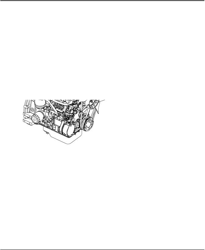
403F-15T
Illustration 13 |
g03246538 |
Typical example
16 |
SEBU8609 |
General Information
Model View Illustrations
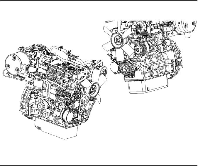
404F-22
Illustration 14 |
g03246558 |
Typical example
SEBU8609 |
17 |
General Information
Model View Illustrations
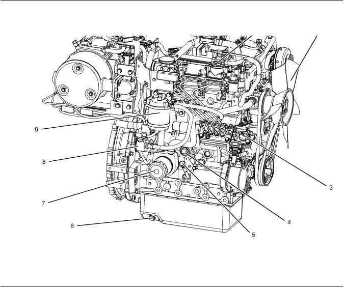
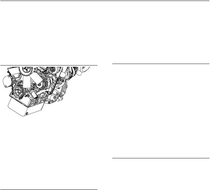
404F-22T
Illustration 15 |
|
|
|
g03246676 |
|
(1) |
Top oil filler |
(4) |
Cylinder block drain plug |
(7) |
Oil filter |
(2) Fan |
(5) Oil gauge (Dipstick) |
(8) Electric fuel pump |
|||
(3) |
Side oil filler |
(6) |
Rear oil drain plug |
(9) |
Secondary fuel filter |
18 |
SEBU8609 |
General Information
Model View Illustrations
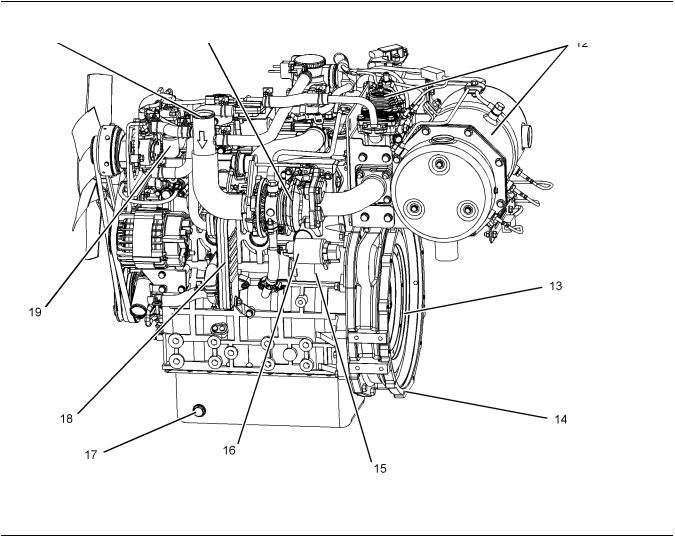
Illustration 16 |
|
g03246563 |
(10) Air intake |
(14) Flywheel housing |
(18) NOx reduction system cooler |
(11) Turbocharger |
(15) Starting motor |
(19) Coolant outlet |
(12) Aftertreatment system |
(16) Solenoid for starting motor |
|
(13) Flywheel |
(17) Front oil drain plug |
|
SEBU8609 |
19 |
General Information
Model View Illustrations
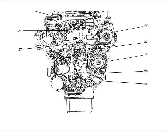
Illustration 17 |
|
g03249056 |
(20) Engine crankcase breather |
(23) Air pump drive belt |
(26) Coolant intake |
(21) Rear lifting eye bracket |
(24) Alternator |
(27) Water pump |
(22) Air pump |
(25) Fan and alternator drive belt |
(28) Front lifting eye |
20 |
SEBU8609 |
General Information
Model View Illustrations
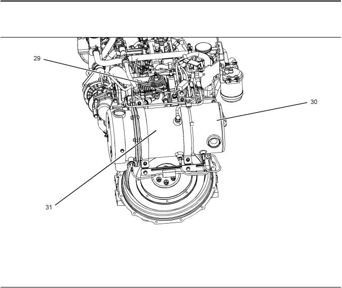
Aftertreatment System
Illustration 18 |
g03249241 |
(29) Aftertreatment Regeneration Device |
(30) Diesel Oxidation Catalyst (DOC) |
(ARD), also known as the (Burner) |
(31) Diesel Particulate Filter (DPF) |
SEBU8609 |
21 |
General Information
Model View Illustrations
Off Engine Parts
Illustration 19 |
g03271819 |
(32)Electronic Control Unit (ECM)
(33)In line fuel filter

22 |
SEBU8609 |
General Information
Product Description
Engine with Low Mounted Air Pump
Illustration 20
i05139813
Product Description
The 400F models are indirect injection engines. The fuel injection pump is operated by a solenoid that is controlled by a Pulse Width Modulation (PWM) signal from the ECM.
The cylinder head assembly has one inlet valve and one exhaust valve for each cylinder. Each cylinder valve has a single valve spring.
The pistons have two compression rings and an oil control ring. It is important to ensure the correct piston height so that the piston does not contact the cylinder head. The correct piston height also ensures efficient combustion of fuel that is necessary in order to conform to requirements for emissions.
g03321871
The crankshaft for a three cylinder engine has four main bearing journals. The crankshaft for a four cylinder engine has five main bearing journals. End play is controlled by the thrust washers that are located on the rear main bearing.
The timing gears are stamped with timing marks in order to ensure the correct assembly of the gears. With the timing marks on the crankshaft gear camshaft gear and the idler gear aligned No. 1 piston will be at top center compression stroke.
The crankshaft gear turns the idler gear which then turns the camshaft gear and the gear for the engine oil pump.
The fuel injection pump is mounted in the cylinder block. The fuel injection pump is operated by the camshaft. The fuel pump is located on the right-hand side of the cylinder block. The fuel pump is electrically operated.

SEBU8609
The fuel injection pump conforms to requirements for emissions. If any adjustments to the fuel injection pump timing and high idle are required, you must refer to your Perkins distributor your Perkins dealer.
A gerotor oil pump is located in the center of the idler gear. The engine oil pump sends lubricating oil to the main oil gallery through a pressure relief valve and an engine oil filter. The rocker arms receive pressurized oil through an externally located oil line that runs from the main oil gallery to the cylinder head.
Coolant from the bottom of the radiator passes through the belt driven centrifugal water pump. The coolant is cooled by the radiator and the temperature is regulated by a water temperature regulator.
Engine efficiency, efficiency of emission controls, and engine performance depend on adherence to correct operation and maintenance recommendations.
Engine performance and efficiency also depend on
the use of recommended fuels, lubrication oils, and coolants. Refer to the Operation and Maintenance
Manual, “Maintenance Interval Schedule” for more information on maintenance items.
Engine Specifications
Note: The front end of the engine is opposite the flywheel end of the engine. The left and the right side of the engine are determined from the flywheel end. The No. 1 cylinder is the front cylinder.
403F-15T Engine
Illustration 21 |
g00852304 |
(A)Exhaust valves
(B)Inlet valves
Table 1
403F-15T Engine Specifications
Maximum Operating Speed
2800 rpm
(rpm)
Cylinders and Arrangement |
In-Line 3 cylinder |
(continued)
23
General Information
Product Description
(Table 1, contd) |
|
|
Bore |
84 mm (3.31 inch) |
|
Stroke |
90 mm (3.54 inch) |
|
Displacement |
1.496 L (91.291 in3) |
|
Aspiration |
T(1) |
|
Compression Ratio |
22.5:1 |
|
Firing Order |
1-2-3 |
|
Rotation that is viewed from the |
Counterclockwise |
|
flywheel |
||
|
||
Valve Lash Setting (Inlet) |
0.20 mm (0.008 inch) |
|
Valve Lash Setting (Exhaust) |
0.20 mm (0.008 inch) |
|
Injection |
Indirect |
|
(1) Turbocharged |
|
404F-22 Engine
Illustration 22 |
g00296424 |
(A)Exhaust valves
(B)Inlet valves
Table 2
404F-22 Engine Specifications
Maximum Operating Speed |
3000 rpm |
|
(rpm) |
||
|
||
Cylinders and Arrangement |
In-Line 4 cylinder |
|
Bore |
84.0 mm (3.31 inch) |
|
Stroke |
100.0 mm (3.94 inch) |
|
Displacement |
2.216 L (135.229 in3) |
|
Aspiration |
NA(1) |
|
Compression Ratio |
23.3:1 |
|
Firing Order |
1-3-4-2 |
|
|
(continued) |

24
General Information
Product Description
(Table 2, contd)
Rotation that is viewed from the flywheel
Valve Lash Setting (Inlet)
Valve Lash Setting (Exhaust)
Injection
(1) Naturally Aspirated
Counterclockwise
0.20 mm (0.008 inch)
0.20 mm (0.008 inch)
Indirect
404F-22T Engine
Illustration 23 |
g00296424 |
(A)Exhaust valves
(B)Inlet valves
Table 3
404F-22T Engine Specifications
Maximum Operating Speed |
3000 rpm |
|
(rpm) |
||
|
||
Cylinders and Arrangement |
In-Line 4 cylinder |
|
Bore |
84.0 mm (3.31 inch) |
|
Stroke |
100.0 mm (3.94 inch) |
|
Displacement |
2.216 L (135.229 in3) |
|
Aspiration |
T(1) |
|
Compression Ratio |
23.5:1 |
|
Firing Order |
1-3-4-2 |
|
Rotation that is viewed from the |
Counterclockwise |
|
flywheel |
||
|
||
Valve Lash Setting (Inlet) |
0.20 mm (0.008 inch) |
|
Valve Lash Setting (Exhaust) |
0.20 mm (0.008 inch) |
|
Injection |
Indirect |
|
(1) Turbocharged |
|
SEBU8609
Electronic Engine Features
The engine operating conditions are monitored. The Electronic Control Module (ECM) controls the response of the engine to these conditions and to the demands of the operator. These conditions and operator demands determine the precise control of fuel injection by the ECM. The electronic engine control system provides the following features:
•Engine monitoring
•Engine speed governing
•System diagnostics
•Aftertreatment Regeneration
•NOx reduction system control on the 404F-22T engine
For more information on electronic engine features, refer to the Operation and Maintenance Manual, “Features and Controls” topic (Operation Section).
Engine Diagnostics
The engine has built-in diagnostics in order to ensure that the engine systems are functioning correctly. The operator will be alerted to the condition by a “Stop or Warning” lamp. Under certain conditions, the engine horsepower and the vehicle speed may be limited.
The electronic service tool may be used to display the diagnostic codes.
There are four types of diagnostic codes: active code, logged code, active event and logged event.
Most of the diagnostic codes are logged and stored in
the ECM. For additional information, refer to the Operation and Maintenance Manual, “Engine
Diagnostics” topic (Operation Section).
The ECM provides an electronic governor that controls the injector output in order to maintain the desired engine rpm.
Engine Service Life
Engine efficiency and maximum utilization of engine performance depend on the adherence to proper operation and maintenance recommendations. In
addition, use recommended fuels, coolants, and lubricants. Use the Operation and Maintenance
Manual as a guide for required engine maintenance.
Expected engine life is generally predicted by the average power that is demanded. The average power that is demanded is based on fuel consumption of the engine over a period of time. Reduced hours of operation at full throttle and/or operating at reduced throttle settings result in a lower average power demand. Reduced hours of operation will increase the length of operating time before an engine overhaul is required.

SEBU8609
Aftermarket Products and Perkins
Engines
Perkins does not warrant the quality or performance of non-Perkins fluids and filters.
When auxiliary devices, accessories, or consumables (filters, additives, catalysts,) which are made by other manufacturers are used on Perkins products, the Perkins warranty is not affected simply because of such use.
However, failures that result from the installation or use of other manufacturers devices, accessories, or consumables are NOT Perkins defects. Therefore, the defects are NOT covered under the Perkins warranty.
Aftertreatment System
The aftertreatment system is approved for use by Perkins . In order to be emission-compliant only the approved Perkins aftertreatment system must be used on a Perkins engine.
25
General Information
Product Description
26
Product Identification Information
Plate Locations and Film Locations
Product Identification
Information
i05140083
Plate Locations and Film
Locations
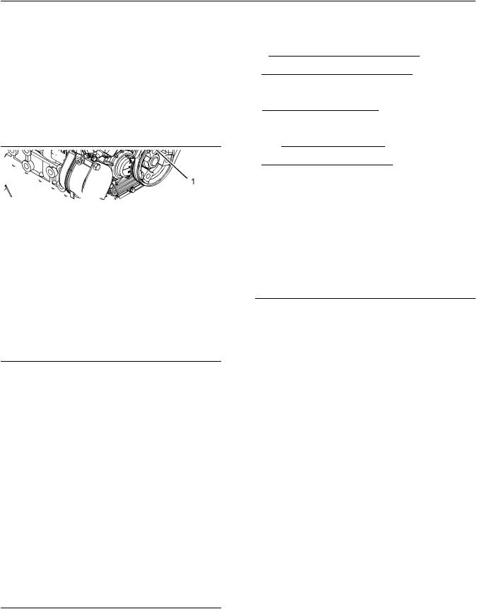
Illustration 24 |
g02335396 |
Typical example
(1) serial number plate
Perkins engines are identified by a serial number. This number is shown on a serial number plate. The serial number plate is mounted above the fuel injection pump on the right-hand side of the engine block.
Illustration 25 |
g01094203 |
Typical example
SEBU8609
An example of an engine number is
ER*****U000001V.
ER |
Engine family |
P |
Type of engine |
***** |
The list number of the engine |
U |
Country of manufacture |
0 |
The first digit is a production code. |
00001 |
Engine Serial Number |
V |
Year of Manufacture |
Perkins |
dealers or Perkins distributors need all of |
these numbers in order to determine the components that were included with the engine. This information permits accurate identification of replacement part numbers.
i05140229
Emissions Certification Film
Illustration 26 |
g02269574 |
Typical example
The emissions label, refer to illustration 26 is installed on the front cover of the engine.

SEBU8609 |
27 |
Product Identification Information
Reference Information
Identifying Numbers on Aftertreatment
Illustration 27 |
g02052934 |
Perkins will supply the fuel label with every engine, refer to illustration 27 . The equipment manufacturer must install the label to the equipment. The label must be attached to the equipment near the inlet of the fuel tank. This action will comply with the EPA regulations. The equipment manufacturer may install another fuel label . If another fuel label is used, the equipment manufacturer must send a drawing or a photo of the label to Perkins. This action will ensure compliance of the label.
i05157330
Reference Information
Information for the following items may be needed to order parts. Locate the information for your engine. Record the information in the appropriate space. Make a copy of this list for a record. Keep the information for future reference.
Record for Reference
Engine Model
Engine Serial number
Engine rpm
In-Line fuel filter
Fuel Filter Element
Lubrication Oil Filter
Crankcase Breather Element
Total Lubrication System Capacity
Total Cooling System Capacity
Air Cleaner Element
Fan Belt
Belt for Air Pump
28
Operation Section
Product Lifting
Operation Section
Lifting and Storage
i05140249
Product Lifting
Illustration 28 |
g03274116 |
Typical example
(1)Front lifting eye
(2)Rear lifting eyes
Note: The engine assembly has three lifting eyes, refer to illustration 28 .
Use a hoist to remove heavy components. Use an adjustable lifting beam to lift the engine. All supporting members (chains and cables) should be parallel to each other. The chains and cables should be perpendicular to the top of the object that is being lifted.
To remove the engine ONLY, use the lifting eyes that are on the engine.
SEBU8609
Lifting eyes are designed and installed for specific engine arrangements. Alterations to the lifting eyes and/or the engine make the lifting eyes and the lifting
fixtures obsolete. If alterations are made, ensure that correct lifting devices are provided. Consult your
Perkins dealer or your Perkins distributor for information regarding fixtures for correct engine lifting.
Lifting Eyes with Top Mounted Aftertreatment
Illustration 29 |
g03321882 |
(1)Front lifting eye
(2)Rear lifting eye
i04053009
Product Storage
(Engine and Aftertreatment)
Perkins are not responsible for damage which may occur when an engine is in storage after a period in service.
Your Perkins dealer or your Perkins distributor can assist in preparing the engine for extended storage periods.
Condition for Storage
The engine must be stored in a water proof building. The building must be kept at a constant temperature. Engines that are filled with Perkins ELC will have coolant protection to an ambient temperature of −36° C (−32.8° F). The engine must not be subjected to extreme variations in temperature and humidity.

SEBU8609
Storage Period
An engine can be stored for up to 6 months provided all the recommendation are adhered to.
Storage Procedure
Keep a record of the procedure that has been completed on the engine.
Note: Do not store an engine that has biodiesel in the fuel system.
1.Ensure that the engine is clean and dry.
a.If the engine has been operated using biodiesel, the system must be drained and new filters installed. The fuel tank will require flushing.
b.Fill the fuel system with an ultra low sulfur fuel. For more information on acceptable fuels refer to this Operation and Maintenance Manual, “Fluid recommendations”. Operate the engine for 15 minutes in order to remove all biodiesel from the system.
2.Drain any water from the primary filter water separator. Ensure that the fuel tank is full.
3.The engine oil will not need to be drained in order to store the engine. Provided the correct specification of engine oil is used the engine can be stored for up to 6 months. For the correct specification of engine oil refer to this Operation and Maintenance Manual, “Fluid recommendations”.
4.Remove the drive belts from the engine.
Sealed Coolant System
Ensure that the cooling system is filled with Perkins
ELC, or an antifreeze that meets ASTM D6210 specification.
Open Cooling System
Ensure that all cooling drain plugs have been opened. Allow the coolant to drain. Install the drain plugs. Place a vapor phase inhibitor into the system. The coolant system must be sealed once the vapor phase inhibitor has been introduced. The effect of the vapor phase inhibitor will be lost if the cooling system is open to the atmosphere.
For maintenance procedures ref to this Operation and Maintenance Manual.
29
Lifting and Storage
Product Storage
Aftertreatment
No special procedures are required. The exhaust outlet of the aftertreatment should be capped. Before storing, the engine and the aftertreatment must be enclosed in a cover.
Monthly Checks
The crankshaft must be rotated in order to change the spring loading on the valve train. Rotate the crankshaft more than 180 degrees. Visibly check for damage or corrosion to the engine and aftertreatment.
Ensure that the engine and aftertreatment are covered completely before storage. Log the procedure in the record for the engine.

30
Features and Controls
Alarms and Shutoffs
Features and Controls
i05142391
Alarms and Shutoffs
• |
ECM |
Electronic Control Module |
• |
DOC |
Diesel Oxidation Catalyst |
• |
DPF |
Diesel Particulate Filter |
• |
ARD |
Aftertreatment Regeneration Device |
Shutoffs
The shutoffs are electrically operated or mechanically operated. The electrically operated shutoffs are controlled by the ECM.
Shutoffs are set at critical levels for the following items:
•Operating temperature
•Operating RPM
•Overspeed
•Aftertreatment regeneration
The particular shutoff may need to be reset before the engine will start.
NOTICE
Always determine the cause of the engine shutdown. Make necessary repairs before attempting to restart the engine.
Be familiar with the following items:
•Types and locations of shutoff
•Conditions which cause each shutoff to function
•The resetting procedure that is required to restart the engine
Alarms
The alarms are electrically operated. The operations of the alarms are controlled by the ECM.
The alarm is operated by a sensor or by a switch. When the sensor or the switch is activated, a signal is sent to the ECM. An event code is created by the ECM. The ECM will send a signal in order to illuminate the lamp. Some application may have a display panel in order to alert the operator.
Your engine may be equipped with the following sensors or switches:
SEBU8609
Coolant temperature – The coolant temperature sensor indicates high jacket water coolant temperature.
Engine oil pressure – The engine oil pressure sensor or switch, indicates when oil pressure drops below rated system pressure, at a set engine speed.
Boost pressure (Intake manifold pressure – The intake manifold pressure sensor checks the rated pressure in the engine manifold.
Intake manifold air temperature – The intake manifold air temperature sensor indicates high intake air temperature.
Atmospheric pressure – The atmospheric pressure sensor checks the air pressure in the location that the engine is operating.
Aftertreatment Alarms
DOC inlet temperature – The inlet temperature sensor checks the operating temperature.
DPF inlet temperature – The inlet temperature sensor checks the operating temperature.
DPF outlet temperature – The outlet temperature sensor checks the operating temperature.
Delta P sensor (Differential pressure) – The sensor checks the differential pressure within the system.
ARD temperature – The sensor checks the temperature within the burner in the ARD system
Testing
Turning the keyswitch to the ON position will check the indicator lights on the control panel. All the indicator lights will be illuminated for 2 seconds after the keyswitch is operated. Replace suspect bulbs immediately.
If any lamps stay illuminated or flashes, the fault must be investigated immediately. The fault will create a diagnostic code.
Refer to Troubleshooting, “Diagnostic Trouble Code” for more information.
i05140291
Gauges and Indicators
Your engine may not have the same gauges or all of the gauges that are described. For more information about the gauge package, see the OEM information.
 Loading...