


SENR9983
October 2005
Disassembly and
Assembly
1106D Industrial Engine
PJ (Engine )
Important Safety Information
Most accidents that involve product operation, maintenance and repair are caused by failure to observe basic safety rules or precautions. An accident can often be avoided by recognizing potentially hazardous situations before an accident occurs. A person must be alert to potential hazards. This person should also have the necessary training, skills and tools to perform these functions properly.
Improper operation, lubrication, maintenance or repair of this product can be dangerous and could result in injury or death.
Do not operate or perform any lubrication, maintenance or repair on this product, until you have read and understood the operation, lubrication, maintenance and repair information.
Safety precautions and warnings are provided in this manual and on the product. If these hazard warnings are not heeded, bodily injury or death could occur to you or to other persons.
The hazards are identified by the “Safety Alert Symbol” and followed by a “Signal Word” such as “DANGER”, “WARNING” or “CAUTION”. The Safety Alert “WARNING” label is shown below.
The meaning of this safety alert symbol is as follows:
Attention! Become Alert! Your Safety is Involved.
The message that appears under the warning explains the hazard and can be either written or pictorially presented.
Operations that may cause product damage are identified by “NOTICE” labels on the product and in this publication.
Perkins cannot anticipate every possible circumstance that might involve a potential hazard. The warnings in this publication and on the product are, therefore, not all inclusive. If a tool, procedure, work method or operating technique that is not specifically recommended by Perkins is used,
you must satisfy yourself that it is safe for you and for others. You should also ensure that the product will not be damaged or be made unsafe by the operation, lubrication, maintenance or repair procedures that you choose.
The information, specifications, and illustrations in this publication are on the basis of information that was available at the time that the publication was written. The specifications, torques, pressures, measurements, adjustments, illustrations, and other items can change at any time. These changes can affect the service that is given to the product. Obtain the complete and most current information before you start any job. Perkins dealers or Perkins distributors have the most current information available.
When replacement parts are required for this product Perkins recommends using Perkins replacement parts.
Failure to heed this warning can lead to premature failures, product damage, personal injury or death.
SENR9983 |
3 |
|
Table of Contents |
Table of Contents |
|
Disassembly and Assembly Section |
|
Fuel Priming Pump - Remove and Install .............. |
4 |
Fuel Filter Base - Remove and Install (Secondary |
|
Fuel Filter) ............................................................. |
7 |
Fuel Transfer Pump - Remove ................................ |
8 |
Fuel Transfer Pump - Install .................................. |
10 |
Fuel Injection Lines - Remove .............................. |
11 |
Fuel Injection Lines - Install ................................. |
12 |
Fuel Manifold (Rail) - Remove and Install ............. |
14 |
Fuel Injection Pump - Remove ............................ |
16 |
Fuel Injection Pump - Install ................................ |
18 |
Fuel Injection Pump Gear - Remove .................... |
22 |
Fuel Injection Pump Gear - Install ........................ |
23 |
Electronic Unit Injector - Remove ......................... |
25 |
Electronic Unit Injector - Install ............................. |
28 |
Turbocharger - Remove ........................................ |
32 |
Turbocharger - Disassemble ................................ |
35 |
Turbocharger - Assemble .................................... |
35 |
Turbocharger - Install ............................................ |
36 |
Wastegate Solenoid - Remove and Install ............ |
40 |
Exhaust Manifold - Remove and Install ............... |
41 |
Exhaust Elbow - Remove and Install ................... |
45 |
Inlet Manifold - Remove and Install ..................... |
46 |
Inlet and Exhaust Valve Springs - Remove and |
|
Install ................................................................... |
48 |
Inlet and Exhaust Valves - Remove and Install .... |
52 |
Engine Oil Filter Base - Remove and Install ........ |
55 |
Engine Oil Cooler - Remove ................................. |
56 |
Engine Oil Cooler - Install ..................................... |
58 |
Engine Oil Relief Valve - Remove and Install ....... |
61 |
Engine Oil Pump - Remove .................................. |
63 |
Engine Oil Pump - Install ...................................... |
64 |
Water Pump - Remove ......................................... |
65 |
Water Pump - Install ............................................. |
66 |
Water Temperature Regulator - Remove and Install |
|
............................................................................. |
67 |
Flywheel - Remove ............................................... |
69 |
Flywheel - Install ................................................... |
70 |
Crankshaft Rear Seal - Remove ........................... |
71 |
Crankshaft Rear Seal - Install ............................... |
72 |
Crankshaft Wear Sleeve (Rear) - Remove and |
|
Install ................................................................... |
75 |
Flywheel Housing - Remove and Install .............. |
76 |
Vibration Damper and Pulley - Remove .............. |
81 |
Vibration Damper and Pulley - Install .................. |
82 |
Crankshaft Front Seal - Remove and Install ......... |
84 |
Crankshaft Wear Sleeve (Front) - Remove and |
|
Install ................................................................... |
85 |
Front Cover - Remove and Install ......................... |
86 |
Gear Group (Front) - Remove and Install ............. |
88 |
Idler Gear - Remove ............................................. |
91 |
Idler Gear - Install ................................................. |
93 |
Housing (Front) - Remove .................................... |
96 |
Housing (Front) - Install ........................................ |
98 |
Accessory Drive - Remove and Install ............... |
100 |
Crankcase Breather - Remove ........................... |
101 |
Crankcase Breather - Install ............................... |
104 |
Valve Mechanism Cover - Remove and Install ... |
108 |
Valve Mechanism Cover Base - Remove and |
|
Install ................................................................. |
109 |
Rocker Shaft and Pushrod - Remove .................. |
111 |
Rocker Shaft - Disassemble ............................... |
112 |
Rocker Shaft - Assemble .................................... |
113 |
Rocker Shaft and Pushrod - Install ...................... |
114 |
Cylinder Head - Remove ..................................... |
116 |
Cylinder Head - Install ......................................... |
118 |
Lifter Group - Remove and Install ....................... |
122 |
Camshaft - Remove and Install ......................... |
123 |
Camshaft Gear - Remove and Install ................ |
125 |
Camshaft Bearings - Remove and Install .......... |
127 |
Engine Oil Pan - Remove .................................. |
129 |
Engine Oil Pan - Install ...................................... |
131 |
Piston Cooling Jets - Remove and Install ........... |
138 |
Pistons and Connecting Rods - Remove ............ |
139 |
Pistons and Connecting Rods - Disassemble ..... |
140 |
Pistons and Connecting Rods - Assemble ......... |
142 |
Pistons and Connecting Rods - Install ................ |
144 |
Connecting Rod Bearings - Remove (Connecting |
|
rods in position) ................................................. |
145 |
Connecting Rod Bearings - Install (Connecting rods |
|
in position) ......................................................... |
146 |
Crankshaft Main Bearings - Remove and Install |
|
(Crankshaft in position) ..................................... |
148 |
Crankshaft - Remove .......................................... |
151 |
Crankshaft - Install .............................................. |
152 |
Crankshaft Timing Ring - Remove and Install .... |
155 |
Crankshaft Gear - Remove and Install .............. |
156 |
Bearing Clearance - Check ................................. |
158 |
Crankshaft Position Sensor - Remove and |
|
Install ................................................................. |
159 |
Coolant Temperature Sensor - Remove and |
|
Install ................................................................. |
159 |
Engine Oil Pressure Sensor - Remove and Install |
|
........................................................................... |
161 |
Position Sensor (Fuel Injection Pump) - Remove and |
|
Install ................................................................. |
162 |
Fuel Pressure Sensor - Remove and Install ....... |
163 |
Boost Pressure Sensor - Remove and Install ..... |
164 |
Inlet Air Temperature Sensor - Remove and |
|
Install ................................................................. |
165 |
Glow Plugs - Remove and Install ....................... |
166 |
Alternator Belt - Remove and Install .................. |
167 |
Fan - Remove and Install ................................... |
168 |
Fan Drive - Remove and Install ......................... |
169 |
Electronic Control Module - Remove and Install .. |
170 |
ECM Mounting Bracket - Remove and Install ..... |
172 |
Alternator - Remove ............................................ |
175 |
Alternator - Install ................................................ |
176 |
Electric Starting Motor - Remove and Install ..... 177 |
|
Index Section |
|
Index ................................................................... |
178 |
4 |
SENR9983 |
Disassembly and Assembly Section |
|
Disassembly and Assembly
Section
i02295884
Fuel Priming Pump - Remove and Install
Removal Procedure (Manual
Priming Pump)
NOTICE
Ensure that all adjustments and repairs that are carried out to the fuel system are performed by authorised personnel that have the correct training.
Before begining ANY work on the fuel system, refer to Operation and Maintenance Manual, “General Hazard Information and High Pressure Fuel Lines” for safety information.
Refer to Testing and Adjusting Manual, “Cleanliness of Fuel System Components” for detailed information on the standards of cleanliness that must be observed during ALL work on the fuel system.
1.Isolate the fuel supply.
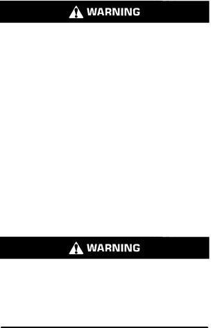
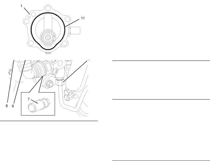
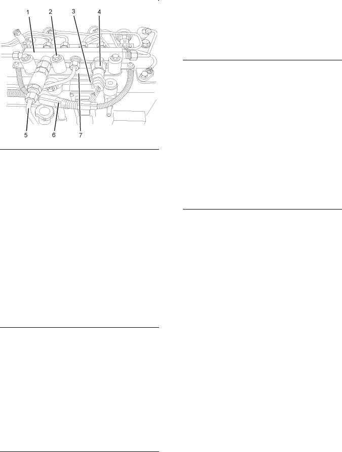
2.Make a temporary identification mark on the plastic tube assemblies (1) in order to show the correct position of the tube assemblies.
3.Place a suitable container below the fuel priming pump in order to catch any fuel that might
be spilled. Drain the primary filter (7). Refer to Operation and Maintenance Manual, “Fuel
System Primary Filter (Water Seperator) Element - Replace”.
Note: Clean up any spillage of fuel immediately.
Illustration 1 |
g01181971 |
|
|
Typical example |
|
4.Disconnect the plastic tube assemblies (1). Plug the tube assemblies with new plugs. Cap the open connectors (2) on the fuel priming pump with new caps.
5.Remove the primary filter (7) from the fuel priming pump (4). Refer to Operation and Maintenance Manual, “Fuel System Primary Filter (Water Seperator) Element - Replace”.
6.Remove the two setscrews (6) from the fuel priming pump (4). Remove the fuel priming pump
(4) from the mounting bracket.
7.If necessary, follow Steps 7.a through 7.c in order to disassemble the fuel priming pump (4).
a. Remove the connectors (2) from the fuel priming pump (4).
b. Remove the plugs (5) from the fuel priming pump (4).
c. Remove the O-ring seals (3) from the connectors (2) and the plugs (5). Discard the O-ring seals.

SENR9983 |
5 |
|
Disassembly and Assembly Section |
Removal Procedure (Electric Fuel
Priming Pump)
NOTICE
Ensure that all adjustments and repairs that are carried out to the fuel system are performed by authorised personnel that have the correct training.
Before begining ANY work on the fuel system, refer to Operation and Maintenance Manual, “General Hazard Information and High Pressure Fuel Lines” for safety information.
Refer to Testing and Adjusting Manual, “Cleanliness of Fuel System Components” for detailed information on the standards of cleanliness that must be observed during ALL work on the fuel system.
1. Isolate the fuel supply.
7.Remove the electric priming pump (4) from the mounting bracket.
Installation Procedure (Manual
Priming Pump)
NOTICE
Ensure that all adjustments and repairs that are carried out to the fuel system are performed by authorised personnel that have the correct training.
Before begining ANY work on the fuel system, refer to Operation and Maintenance Manual, “General Hazard Information and High Pressure Fuel Lines” for safety information.
Refer to Testing and Adjusting Manual, “Cleanliness of Fuel System Components” for detailed information on the standards of cleanliness that must be observed during ALL work on the fuel system.
1.Ensure that the fuel priming pump (4) is clean and free from wear or damage. If necessary, replace the fuel priming pump.
Illustration 2 |
g01186418 |
|
|
Typical example |
|
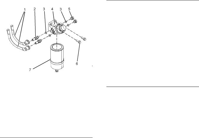
2.Isolate the electrical supply.
3.Disconnect the electrical lead (3) for the electric priming pump (4).
4.Make a temporary identification mark on the plastic tube assemblies (1) and (2) in order to show the correct position of the tube assemblies.
5.Disconnect the plastic tube assemblies (1) and (2). Plug the tube assemblies with new plugs. Cap the ports in the fuel priming pump (4) with new caps.
6.Remove the four setscrews (5) from the electric priming pump (4).
Illustration 3 |
g01181971 |
|
|
Typical example |
|
2.If necessary, follow Steps 2.a through 2.d in order to assemble the fuel priming pump (4).
a.Install new O-ring seals (3) to the connectors
(2) and to the plugs (5).
b.Install the connectors (2) to the fuel priming pump (4).
c.Install the plugs (5) to the fuel priming pump (4).
6 |
SENR9983 |
Disassembly and Assembly Section |
|
d.Tighten the plugs and the connectors to a torque of 20 N·m (14 lb ft).
3.Position the fuel priming pump (4) on the mounting bracket. Install the two setscrews (6) to the fuel priming pump . Tighten the setscrews to a torque of 44 N·m (32 lb ft).
4.Remove the plugs from the plastic tube assemblies. Remove the caps from the connectors.
5.Connect the plastic tube assemblies (1) to the connectors (2).
Note: Ensure that the plastic tube assemblies are installed in the original positions.
6.Install a new primary filter (7) to the fuel priming pump (4). Refer to Operation and Maintenance Manual, “Fuel System Primary Filter (Water Seperator) Element - Replace”.
7.Restore the fuel supply.
8.Prime the fuel system. Refer to Operation and Maintenance Manual, “Fuel System - Prime”.
Installation Procedure (Electric
Fuel Priming Pump)
NOTICE
Ensure that all adjustments and repairs that are carried out to the fuel system are performed by authorised personnel that have the correct training.
Before begining ANY work on the fuel system, refer to Operation and Maintenance Manual, “General Hazard Information and High Pressure Fuel Lines” for safety information.
Refer to Testing and Adjusting Manual, “Cleanliness of Fuel System Components” for detailed information on the standards of cleanliness that must be observed during ALL work on the fuel system.
1.Ensure that the electric priming pump (4) is clean and free from wear or damage. If necessary, replace the electric priming pump.
Illustration 4 |
g01186418 |
|
|
Typical example |
|
2.Position the electric priming pump (4) on the mounting bracket. Install the four setscrews (5) to the electric priming pump (4).
3.Tighten the setscrews (5) to a torque of 9 N·m (79 lb in).
4.Remove the plugs from the plastic tube assemblies. Remove the caps from the electric priming pump.
5.Connect the plastic tube assemblies (1) and (2) to the electric priming pump (4).
Note: Ensure that the plastic tube assemblies are installed in the original positions.
6.Connect the electrical lead (3) for the electric priming pump (4).
7.Restore the electrical supply.
8.Restore the fuel supply.
9.Prime the fuel system. Refer to Operation and Maintenance Manual, “Fuel System - Prime”.
SENR9983 |
7 |
|
Disassembly and Assembly Section |
i02295889
Fuel Filter Base - Remove and Install
(Secondary Fuel Filter)
Removal Procedure
NOTICE
Ensure that all adjustments and repairs that are carried out to the fuel system are performed by authorised personnel that have the correct training.
Before begining ANY work on the fuel system, refer to Operation and Maintenance Manual, “General Hazard Information and High Pressure Fuel Lines” for safety information.
Refer to Testing and Adjusting Manual, “Cleanliness of Fuel System Components” for detailed information on the standards of cleanliness that must be observed during ALL work on the fuel system.
1. Isolate the fuel supply.
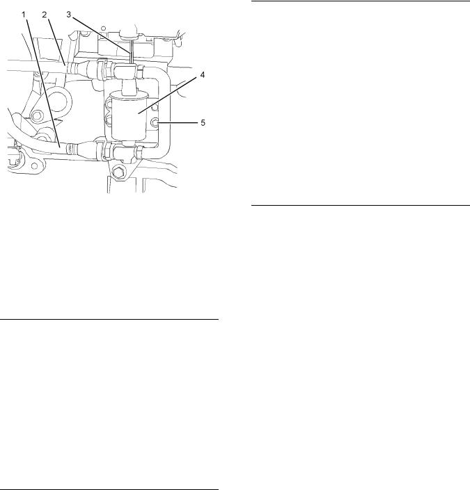
4.Disconnect the plastic tube assemblies (3), (4) and (5) from the fuel filter base (1). Plug the plastic tube assemblies with new plugs. Cap the ports in the fuel filter base with new caps.
5.Remove the fuel filter (6). Refer to Operation and Maintenance Manual, “Fuel System Secondary Filter - Replace”.
6.Remove the two setscrews (2) from the fuel filter base (1). Remove the fuel filter base from the mounting bracket.
Note: Do not disassemble the fuel filter base.
Installation Procedure
NOTICE
Ensure that all adjustments and repairs that are carried out to the fuel system are performed by authorised personnel that have the correct training.
Before begining ANY work on the fuel system, refer to Operation and Maintenance Manual, “General Hazard Information and High Pressure Fuel Lines” for safety information.
Refer to Testing and Adjusting Manual, “Cleanliness of Fuel System Components” for detailed information on the standards of cleanliness that must be observed during ALL work on the fuel system.
1.Ensure that the fuel filter base (1) is clean and free from damage. If necessary, replace the complete fuel filter base and filter assembly.
Illustration 5 |
g01165584 |
|
|
Typical example |
|
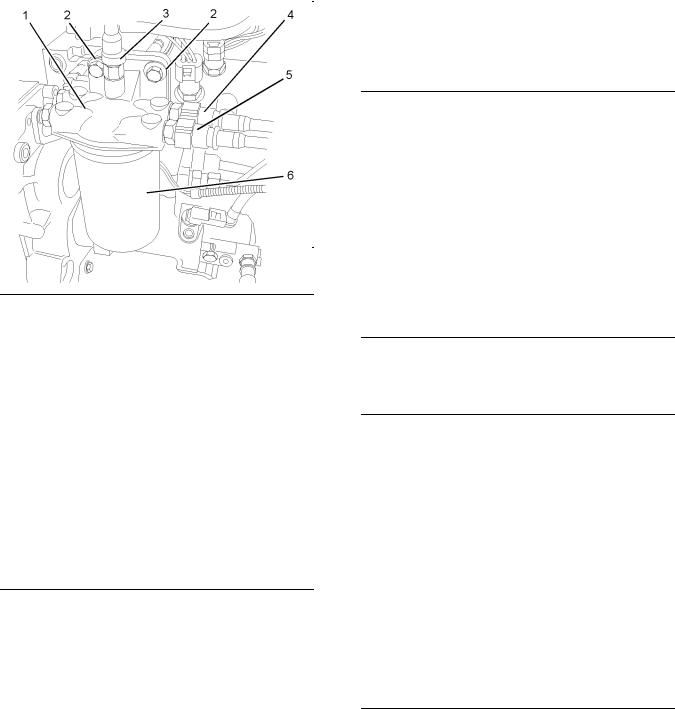
2.Make temporary identification marks on the plastic tube assemblies (3), (4) and (5) in order to show the correct position of the tube assemblies.
3.Place a suitable container below the fuel filter base in order to catch any fuel that might be spilled.
Note: Clean up any spillage of fuel immediately.
Illustration 6 |
g01165584 |
|
|
Typical example |
|

8 |
SENR9983 |
Disassembly and Assembly Section |
|
2.Position the fuel filter base (1) on the mounting bracket. Install the setscrews (2). Tighten the setscrews to a torque of 44 N·m (32 lb ft).
3.Remove the plugs from the plastic tube assemblies. Remove the caps from the ports in the fuel filter base.
NOTICE
Ensure that the plastic tube assemblies are installed in the original positions. Failure to connect the plastic tube assemblies to the correct ports will allow contamination to enter the fuel system. Contaminated fuel will cause serious damage to the engine.
4.Connect the plastic tube assemblies (3), (4) and
(5) to the fuel filter base (1).
Note: Ensure that the plastic tube assemblies are installed in the original positions. Failure to connect the plastic tube assemblies to the correct ports will allow contamination to enter the fuel system.
Contaminated fuel will cause serious damage to the engine.
5.If necessary, install a new fuel filter (6) to the fuel filter base (1). Refer to Operation and Maintenance Manual, “Fuel System Secondary Filter - Replace” for the correct procedure.
6.Restore the fuel supply.
End By:
a.Remove the air from the fuel system. Refer to Operation and Maintenance Manual, “Fuel System - Prime”.
i02296828
Fuel Transfer Pump - Remove
Removal Procedure
NOTICE
Ensure that all adjustments and repairs that are carried out to the fuel system are performed by authorised personnel that have the correct training.
Before begining ANY work on the fuel system, refer to Operation and Maintenance Manual, “General Hazard Information and High Pressure Fuel Lines” for safety information.
Refer to Testing and Adjusting Manual, “Cleanliness of Fuel System Components” for detailed information on the standards of cleanliness that must be observed during ALL work on the fuel system.
1.Isolate the fuel supply.
2.Place a suitable container below the fuel transfer pump (1) in order to catch any fuel that might be spilled.
Note: Clean up any spillage of fuel immediately.
SENR9983 |
9 |
|
|
|
Disassembly and Assembly Section |
|
|
|
Illustration 7 |
g01162545 |
|
|
Typical example |
|
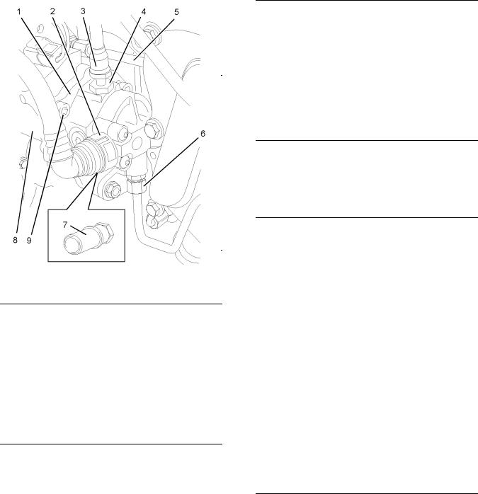
3.Remove the plastic tube assembly (2) from the fuel transfer pump (1).
4.Disconnect the plastic tube assembly (3) from the outlet of the fuel transfer pump (1).
5.Remove the connector (4) from the fuel transfer pump (1). Remove the O-ring seal (not shown) from the connector (4). Discard the O-ring seal.
If necessary, remove the connector (7) from the fuel transfer pump (1). Remove the O-ring seal (not shown) from the connector (7). Discard the O-ring seal.
6.Remove the tube assembly (6) for the fuel return from the fuel transfer pump and the cylinder head.
Note: Disconnect the tube assembly at the fuel transfer pump first in order to drain the fuel from the cylinder head.
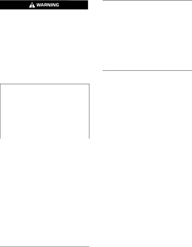
7.Remove the tube assembly (5) for the engine oil supply from the fuel injection pump (8).
8.Plug or cap all open ports and tube assemblies immediately with new plugs or caps.
9.Use an allen wrench with a ball end in order to remove the five allen head screws (9) that secure the fuel transfer pump to the fuel injection pump
(8).
Illustration 8 |
g01162543 |
|
10. Remove fuel transfer pump (1) from the fuel injection pump (8).
Note: Do not remove the dowels (10) from the fuel injection pump.
Illustration 9 |
g01162544 |
|
11. Remove the O-ring seal (11) from the fuel transfer pump (1). Discard the O-ring seal.
10 |
SENR9983 |
Disassembly and Assembly Section |
|
i02296829
Fuel Transfer Pump - Install
Installation Procedure
NOTICE
Ensure that all adjustments and repairs that are carried out to the fuel system are performed by authorised personnel that have the correct training.
Before begining ANY work on the fuel system, refer to Operation and Maintenance Manual, “General Hazard Information and High Pressure Fuel Lines” for safety information.
Refer to Testing and Adjusting Manual, “Cleanliness of Fuel System Components” for detailed information on the standards of cleanliness that must be observed during ALL work on the fuel system.
1.Ensure that the mating faces of the fuel injection pump (8) and the fuel transfer pump (1) are clean and free from damage.
Illustration 11 |
g01162543 |
|
3.Align the holes in the fuel transfer pump (1) with the dowels (10) in the fuel injection pump (8). Install the fuel transfer pump to the fuel injection pump.
Illustration 10 |
g01162544 |
|
2.Install a new O-ring seal (11) to fuel transfer pump
(1). Lubricate the O-ring seal with clean engine oil.
Illustration 12 |
g01162545 |
|
|
Typical example |
|
4. Use an allen wrench with a ball end to install the five allen head screws (9). Tighten the allen head screws to a torque of 30 N·m (22 lb ft).
5. Remove the plugs and the caps from the ports and tube assemblies.
SENR9983 |
11 |
|
Disassembly and Assembly Section |
6.Install the tube assembly (5) for the engine oil supply to the fuel injection pump (8) and to the cylinder block.
7.Install the tube assembly (6) for the fuel return to the fuel transfer pump (1) and to the cylinder head.
8.Install a new O-ring seal (not shown) to the connector (4). Install the connector (4) to the fuel transfer pump (1). Tighten the connector to torque of 15 N·m (11 lb ft).
9.If necessary, install a new O-ring seal (not shown) to the connector (7) and install the connector (7) to the fuel transfer pump (1). Tighten the connector to torque of 15 N·m (11 lb ft).
10.Connect the plastic tube assembly (3) to the outlet of the fuel transfer pump (1).
11.Install the plastic tube assembly (2) to the fuel transfer pump (1).
12.Restore the fuel supply.
13.Remove the air from the fuel system. Refer to Testing and Adjusting Manual, “Fuel System - Prime”.
i02295890
Fuel Injection Lines - Remove
Removal Procedure
Table 1
Required Tools
Tool |
Part |
Part Name |
Qty |
|
Number |
||||
|
|
|
||
|
|
|
|
|
A |
U5MK1124 |
Cap Kit |
1 |
|
|
|
|
|
Contact with high pressure fuel may cause fluid penetration and burn hazards. High pressure fuel spray may cause a fire hazard. Failure to follow these inspection, maintenance and service instructions may cause personal injury or death.
NOTICE
Ensure that all adjustments and repairs that are carried out to the fuel system are performed by authorised personnel that have the correct training.
Before begining ANY work on the fuel system, refer to Operation and Maintenance Manual, “General Hazard Information and High Pressure Fuel Lines” for safety information.
Refer to Testing and Adjusting Manual, “Cleanliness of Fuel System Components” for detailed information on the standards of cleanliness that must be observed during ALL work on the fuel system.
1.Isolate the fuel supply.
2.Isolate the electrical supply.
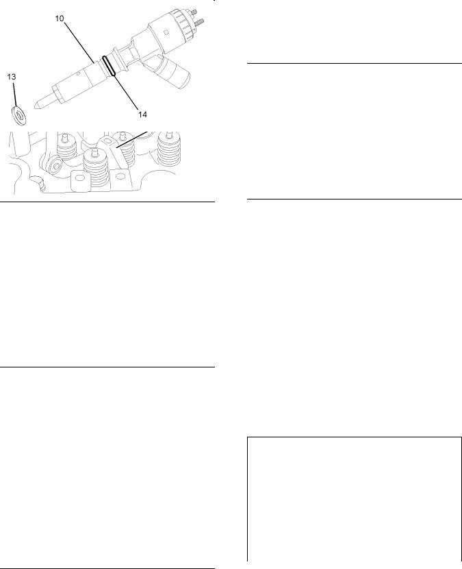
Illustration 13 |
g01178882 |
|
|
Typical example |
|
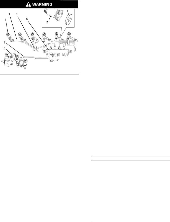
3.Remove the two plastic clamps (2) from the fuel injection lines (1). Discard the plastic clamps.
4.Slide the dust seal (3) from the nut on the fuel injection line (1).
5.Disconnect the fuel injection line (1) at the electronic unit injector (4).
6.Disconnect the fuel injection line (1) at the fuel manifold (5).
7.Remove the fuel injection line (1). Discard the fuel injection line.
Note: Clean up any spillage of fuel immediately.
12 |
SENR9983 |
Disassembly and Assembly Section |
|
8.Plug the open port in the fuel manifold (5) immediately. Use Tooling (A) in order to plug the open port in the fuel manifold.
9.Remove the seal (6) from the electronic unit injector (4) and the base of the valve mechanism cover (not shown).
Note: The seal can be damaged by contact with fuel.
10.Plug the open port in electronic unit injector (4) immediately. Use Tooling (A) in order to plug the open port in the electronic unit injector.
11.Repeat Steps 4 through 11 in order to remove the remaining fuel injection lines from the fuel manifold to the electronic unit injectors.
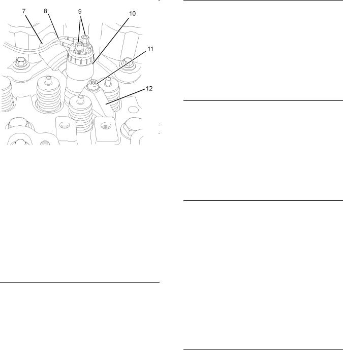
Illustration 14 |
g01198424 |
|
|
Typical Example |
|
12. Disconnect the harness assembly (9) from the fuel injection pump (8). Slide the locking tab (10) into the unlocked position. Disconnect the harness assembly (9) from the position sensor (11). Position the harness assembly (9) so that the harness assembly is clear of the fuel injection line (7).
Illustration 15 |
g01208398 |
|
Illustration 16 |
g01208399 |
|
|
Assembly of the tube clip |
|
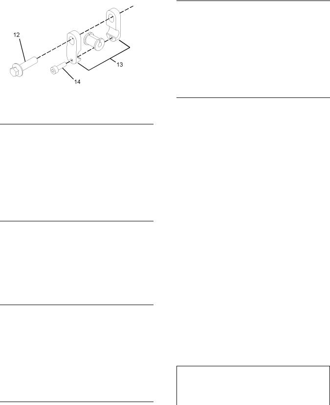
13.Remove the fasteners (12) from the three tube clips (13) that secure the fuel injection line (7). Loosen the three allen head screws (14). Position the tube clips in order to allow removal of the fuel injection line.
14.Disconnect the fuel injection line (7) at the fuel injection pump (8).
15.Disconnect the fuel injection line (7) at the fuel manifold (5).
16.Plug all open ports immediately. Use Tooling (A) in order to plug the open ports in the fuel manifold
(5)and in the fuel injection pump (8).
17.Remove the fuel injection line (7).
Note: Clean up any spillage of fuel immediately.
18. Remove the allen head screws (14) and the assemblies of the three tube clips (13) from fuel injection line (7). Discard the fuel injection line.
i02295912
Fuel Injection Lines - Install
Installation Procedure
Table 2
Required Tools
Tool |
Part |
Part Name |
Qty |
|
Number |
||||
|
|
|
||
|
|
|
|
|
A |
27610294 |
Injector Pipe Nut Tool |
1 |
|
|
|
|
|

SENR9983 |
13 |
|
Disassembly and Assembly Section |
NOTICE
Ensure that all adjustments and repairs that are carried out to the fuel system are performed by authorised personnel that have the correct training.
Before begining ANY work on the fuel system, refer to Operation and Maintenance Manual, “General Hazard Information and High Pressure Fuel Lines” for safety information.
Refer to Testing and Adjusting Manual, “Cleanliness of Fuel System Components” for detailed information on the standards of cleanliness that must be observed during ALL work on the fuel system.
Note: The following procedure should be adopted in order to install the fuel injection lines when the electronic unit injectors or the fuel manifold have not been removed. If the electronic unit injectors or the fuel manifold have been removed, refer to
Disassembly and Assembly Manual, “Electronic Unit Injector - Install” and Disassembly and Assembly Manual, “Fuel Manifold - Install” for more information.
1.Loosely install the assemblies of the three tube clips (13) and the allen head screws (14) to the fuel injection line (7).
2.Place the fuel injection line (7) in position.
3.Remove the caps from the port in the fuel injection pump (8) and from the appropriate port in the fuel manifold (5). Remove the caps from the new fuel injection line (7).
4.Loosely connect the nuts at both ends of the fuel injection line (7), to the fuel manifold (5) and to the fuel injection pump (8). Ensure that the ends of the fuel injection line are correctly seated in the fuel injection pump and in the fuel manifold.
5.Use Tooling (A) to tighten the nuts on the fuel injection line (7) to a torque of 30 N·m (22 lb ft).
6.Install the setscrews (12) for the three tube clips (13) that secure the fuel injection line (7). Tighten the setscrews (12) to a torque of 22 N·m (16 lb ft). Tighten the M5 allen head screws (14) to a torque of 10 N·m (89 lb in). Ensure that fuel injection line does not contact any other engine component.
|
|
Illustration 19 |
g01198424 |
|
Illustration 17 |
g01208399 |
|||
|
||||
Typical example |
|
|||
|
|
|||
Assembly of the tube clip |
|
|
||
|
|
|
7. Connect the harness assembly (9) to the position sensor (11). Slide the locking tab (10) into the locked position. Connect the harness assembly
(9) to the fuel injection pump (8).
Illustration 18 |
g01208398 |
|
14 |
SENR9983 |
Disassembly and Assembly Section |
|
Illustration 20 |
g01178882 |
|
|
Typical example |
|
8.Thoroughly clean the seal (6). Inspect the seal for damage. If necessary, replace the seal.
Note: The seal can be damaged by contact with fuel. If the seal has been in contact with fuel for a prolonged period, the seal should be replaced.
9.Install the seal (6) to the electronic unit injector
(4). Ensure that the flange on the seal is flush with the valve mechanism cover base.
10.Remove the caps from the new fuel injection line
(1). Ensure that a new dust seal (3) is installed to the fuel injection line.
11.Remove the caps from the electronic unit injector
(4)and from the appropriate port in the fuel manifold (5).
12.Loosely connect the nuts at both ends of the fuel injection line (1), to the electronic unit injector (4) and to the appropriate port in the fuel manifold
(5). Ensure that the ends of the fuel injection line are correctly seated in the electronic unit injector and in the fuel manifold.
13.Use Tooling (A) to tighten the nuts on the fuel injection line (1) to a torque of 30 N·m (22 lb ft). Slide the dust seal (3) into position over the nut on the fuel injection line. Ensure that the dust seal (3) is in contact with the seal (6).
14.Follow Steps 8 through 13 in order to install the remaining fuel injection lines.
15. Install two new clamps (2) to the fuel injection lines. Ensure that the clamps are fully closed in order to retain the fuel injection lines.
Note: Ensure that fuel injection lines do not contact any other engine component.
16.Restore the fuel supply.
17.Restore the electrical supply.
18.Remove the air from the fuel system. Refer to the Operations and Maintenance Manual, “Fuel System - Prime”.
i02403286
Fuel Manifold (Rail) - Remove and Install
Removal Procedure
Start By:
a.Remove the fuel injection lines. Refer to Disassembly and Assembly Manual, “Fuel Injection Lines - Remove”.
b.If necessary, remove the fuel pressure sensor. Refer to Disassembly and Assembly Manual, “Fuel Pressure Sensor - Remove and Install”.
Contact with high pressure fuel may cause fluid penetration and burn hazards. High pressure fuel spray may cause a fire hazard. Failure to follow these inspection, maintenance and service instructions may cause personal injury or death.
NOTICE
Ensure that all adjustments and repairs that are carried out to the fuel system are performed by authorised personnel that have the correct training.
Before begining ANY work on the fuel system, refer to Operation and Maintenance Manual, “General Hazard Information and High Pressure Fuel Lines” for safety information.
Refer to Testing and Adjusting Manual, “Cleanliness of Fuel System Components” for detailed information on the standards of cleanliness that must be observed during ALL work on the fuel system.
SENR9983 |
15 |
|
Disassembly and Assembly Section |
1. Ensure that all ports on the fuel manifold are capped. Ensure that the fuel manifold is externally clean and free from damage.
Note: Do not install a fuel manifold that has not been capped. All caps must be left in place until the fuel injection lines or the fuel pressure sensor are installed.
Illustration 21 |
g01190733 |
|
The fuel manifold is shown with fuel injection lines in position.
1.If the fuel sensor (4) has not been removed from the fuel manifold (1), slide the locking tab (3) into the unlocked position. Disconnect the plug on the harness assembly (6) from the fuel pressure sensor (4).
2.Disconnect the tube assembly (5) from the fuel pressure relief valve on the fuel manifold (1). Immediately cap the open port in the fuel manifold
(1) with a new cap. Immediately plug the open end of the tube assembly (5) with a new plug.
3.Remove the three setscrews (2) from the fuel manifold (1).
4.Remove the fuel manifold (1) from the mounting bracket (7).
Installation Procedure
NOTICE
Ensure that all adjustments and repairs that are carried out to the fuel system are performed by authorised personnel that have the correct training.
Before begining ANY work on the fuel system, refer to Operation and Maintenance Manual, “General Hazard Information and High Pressure Fuel Lines” for safety information.
Refer to Testing and Adjusting Manual, “Cleanliness of Fuel System Components” for detailed information on the standards of cleanliness that must be observed during ALL work on the fuel system.
Illustration 22 |
g01190733 |
|
The fuel manifold is shown with fuel injection lines in position.
2.Position the fuel manifold (1) on the mounting bracket (7).
3.Install the three setscrews (2) to the fuel manifold
(1)finger tight.
4.Install a new set of fuel injection lines and seals. Refer to Disassembly and Assembly Manual, “Fuel Injection Lines - Install” for more information.
5.Tighten the setscrews (2) to a torque of 22 N·m (16 lb ft).
6.Remove the plug from the tube assembly (5). Remove the cap from the appropriate port in the fuel manifold (1). Connect the tube assembly
(5)to the fuel pressure relief valve on the fuel manifold (1).
7.If the fuel pressure sensor (4) was not removed from the fuel manifold (1), connect the plug on the harness assembly (6) to the fuel pressure sensor (4). slide the locking tab (3) into the locked position.
16 |
SENR9983 |
Disassembly and Assembly Section |
|
If the fuel pressure sensor (4) was removed from the fuel manifold (1), install the fuel pressure sensor (4) and a new sealing washer. Refer
to Disassembly and Assembly Manual, “Fuel Pressure Sensor - Revove and Install” for more information.
8.Remove the air from the fuel system. Refer to Operation and Maintenance Manual, “Fuel System - Prime” for more information.
NOTICE
Ensure that all adjustments and repairs that are carried out to the fuel system are performed by authorised personnel that have the correct training.
Before begining ANY work on the fuel system, refer to Operation and Maintenance Manual, “General Hazard Information and High Pressure Fuel Lines” for safety information.
i02295929
Fuel Injection Pump - Remove
Refer to Testing and Adjusting Manual, “Cleanliness of Fuel System Components” for detailed information on the standards of cleanliness that must be observed during ALL work on the fuel system.
Removal Procedure
Table 3
Required Tools
Tool |
Part |
Part Name |
Qty |
|
Number |
||||
|
|
|
||
|
|
|
|
|
A |
21825576 |
Crankshaft Turning Tool |
1 |
|
|
|
|
|
|
A |
27610289 |
Crankshaft Turning Tool |
1 |
|
|
|
|
||
27610290 |
Gear |
1 |
||
|
||||
|
|
|
|
|
B |
27610212 |
Camshaft Timing Pin |
1 |
|
|
|
|
|
|
C |
27610286 |
Crankshaft Timing Pin |
1 |
|
|
|
|
|
|
D |
- |
Cap |
2 |
|
|
|
|
|
Start By:
a.If necessary, remove the fuel filter base. Refer to Disassembly and Assembly Manual, “Fuel Filter Base - Remove and Install”.
b.If necessary, remove the fuel priming pump. Refer to Disassembly and Assembly Manual, “Fuel Priming Pump - Remove”.
c.Remove the front cover. Refer to Disassembly and Assembly Manual, “Front Cover - Remove and Install”.
Note: Either Tooling (A) can be used. Use the Tooling that is most suitable.
Contact with high pressure fuel may cause fluid penetration and burn hazards. High pressure fuel spray may cause a fire hazard. Failure to follow these inspection, maintenance and service instructions may cause personal injury or death.
1.Isolate the fuel supply.
2.Isolate the electrical supply.
3.Use Tooling (A) in order to rotate the crankshaft so that number one piston is at top dead center on the compression stroke. Refer to Testing and Adjusting Manual, “Finding Top Centre Position for No.1 Piston”.
4.Use Tooling (B) in order to lock the camshaft in the correct position. Use Tooling (C) in order to lock the crankshaft in the correct position. Refer to Disassembly and Assembly, “Gear Group (Front) - Remove” for the correct procedure.
5.Remove the backlash from the fuel pump gear. Lock the fuel injection pump in the correct position and remove the fuel pump gear. Refer to Disassembly and Assembly, “Fuel Pump Gear - Remove and Install” for the correct procedure.
SENR9983 |
|
17 |
|
|
|
Disassembly and Assembly Section |
|
|
|
6. Place a suitable container below the fuel injection |
|
|
|
pump (1) in order to catch any fuel that might be |
|
|
|
spilled. |
|
|
|
Note: Clean up any spillage of fuel immediately. |
|
|
|
7. Disconnect the plastic tube assembly (2) from the |
|
|
|
fuel injection pump (1). |
|
|
|
8. Disconnect the engine wiring harness (7) from the |
|
|
|
solenoid (3) of the fuel injection pump. Disconnect |
|
|
|
the engine wiring harness (7) from the position |
|
|
|
sensor (4) for the fuel injection pump. |
|
|
|
Note: The engine wiring harness should be |
|
|
|
positioned in order to avoid an obstruction to the fuel |
|
|
|
injection pump. |
|
|
|
9. Remove the plastic tube assembly (11) from the |
|
|
|
fuel transfer pump (8). |
|
|
|
10. Disconnect the plastic tube assembly (10) from |
|
|
|
the outlet of the fuel transfer pump (8). |
|
|
|
11. Disconnect the plastic tube assembly (5) from the |
|
|
|
fuel injection pump (1). |
|
|
|
12. Remove the tube assembly (12) for the fuel return |
|
|
g01173307 |
||
Illustration 23 |
from the fuel transfer pump and the cylinder head. |
||
|
Typical example
Note: Disconnect the tube assembly at the fuel transfer pump first in order to drain the fuel from the cylinder head.
13. Remove the tube assembly (9) for the engine oil supply to the fuel injection pump (1).
14. Plug or cap all open ports and tube assemblies immediately with new plugs or caps.
15. Remove the fuel injection line (6) that connects the fuel injection pump to the fuel manifold. Refer to Disassembly and Assembly Manual, “Fuel Injection Lines - Remove”. Use Tooling (D) in order to plug the open ports in the fuel injection pump and in the fuel manifold. Discard the fuel injection line.
Illustration 24 |
g01173310 |
|
|
Typical example |
|
18 |
SENR9983 |
Disassembly and Assembly Section |
|
Illustration 25 |
g01208416 |
|
16. Remove the two setscrews (15). Remove the two setscrews (14) and remove the support bracket (13) from the fuel injection pump (1).
Illustration 26 |
g01173314 |
|
|
Typical example |
|
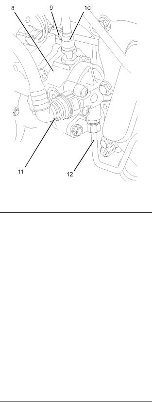
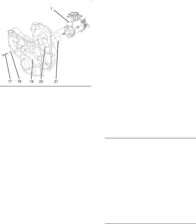
17. Remove the three setscrews (17) and sealing washers (18). Discard the sealing washers.
Note: The fuel injection pump should be supported by hand as the setscrews are removed.
18. Carefully remove the fuel injection pump (1) from the front housing (19). Ensure that the bore (20) in the front housing is not damaged as the fuel injection pump is removed.
19.Remove the O-ring seal (21) from the fuel injection pump (1). Discard the O-ring seal.
20.If necessary, remove the position sensor (4) from the fuel injection pump (1). Refer to Disassembly and Assembly Manual, “Position Sensor (Fuel Injection Pump) - Remove and Install”.
21.If necessary, remove the fuel transfer pump
(8)from the fuel injection pump (1). Refer to Disassembly and Assembly Manual, “Fuel Transfer Pump - Remove”.
i02295933
Fuel Injection Pump - Install
Installation Procedure
Table 4
Required Tools
Tool |
Part |
Part Description |
Qty |
|
Number |
||||
|
|
|
|
|
A |
21825576 |
Crankshaft Turning Tool |
1 |
|
|
|
|
|
|
A |
27610289 |
Crankshaft Turning Tool |
1 |
|
|
|
|
||
27610290 |
Gear |
1 |
||
|
||||
|
|
|
|
|
B |
27610212 |
Camshaft Timing Pin |
1 |
|
|
|
|
|
|
C |
27610286 |
Crankshaft Timing Pin |
1 |
|
|
|
|
|
|
E |
27610302 |
Fuel Injection Pump |
1 |
|
Timing Tool |
||||
|
|
|
||
|
|
|
|
|
F |
21820221 |
POWERPART |
- |
|
Rubber Grease |
||||
|
|
|
Note: Either Tooling (A) can be used. Use the Tooling that is most suitable.
NOTICE
Ensure that all adjustments and repairs that are carried out to the fuel system are performed by authorised personnel that have the correct training.
Before begining ANY work on the fuel system, refer to Operation and Maintenance Manual, “General Hazard Information and High Pressure Fuel Lines” for safety information.
Refer to Testing and Adjusting Manual, “Cleanliness of Fuel System Components” for detailed information on the standards of cleanliness that must be observed during ALL work on the fuel system.
SENR9983 |
19 |
|
Disassembly and Assembly Section |
Illustration 27 |
g01174932 |
|
1.If the fuel injection pump was previously disassembled, follow Steps 1.a and 1.b in order to assemble the fuel injection pump.
a.Install the fuel transfer pump (8) to the fuel injection pump (1). Refer to Disassembly and Assembly Manual, “Fuel Transfer Pump - Install”.
b.Install the position sensor (4) to the fuel injection pump (1). Refer to Disassembly and Assembly Manual, “Position Sensor (Fuel Injection Pump) - Remove and Install”.
Note: A new fuel injection pump assembly includes the fuel transfer pump and the position sensor.
2.To check the fuel injection pump timing, follow Steps 2.a and 2.b.
a.Position Tooling (E) onto the shaft (22) of the fuel injection pump. Align the lever of Tooling
(E) with the key slot (23). Engage the lever into the key slot.
b.Insert the locking pin of Tooling (E) into the hole (24) in fuel injection pump.
If the locking pin can be inserted into the hole, the fuel injection pump timing is correct.
If the locking pin cannot be inserted into the hole, the fuel injection pump timing is not correct.
Note: There should be no resistance when the locking pin is inserted.
3.If the fuel injection pump timing has been lost follow Steps 3.a through 3.e in order to reset the fuel injection pump timing.
a.If necessary, loosen the locking screw (25) on the fuel injection pump. Slide the spacer (26) into position (X). Tighten the locking screw (25) to a torque of 9 N·m (80 lb in). This will prevent the locking screw from tightening against the shaft (22).
The fuel injection pump is now unlocked.
b.Position Tooling (E) onto the shaft (22) of the fuel injection pump. Align the lever of Tooling
(E)with the key slot (23) in the fuel injection pump. Engage the lever into the key slot.
c.Use the lever of Tooling (E) to rotate the shaft (22) until the pin of Tooling (E) can be engaged into the hole (24). Engage the pin of Tooling
(E)into the hole.
d.Loosen the locking screw (25) in the fuel injection pump. Slide the spacer (26) into position (Y). Tighten the locking screw (25) against the shaft of the fuel injection pump to a torque of 9 N·m (80 lb in).
The fuel injection pump is now locked.
e.Remove tooling (E).
Illustration 28 |
g01173314 |
|
|
Typical example |
|
4.Inspect the bore (20) in the front housing (19) for damage. If the bore is damaged, replace the front housing. Refer to Disassembly and Assembly Manual, “Housing (Front) - Remove”
and Disassembly and Assembly Manual, “Housing (Front) - Install”.

20 |
SENR9983 |
Disassembly and Assembly Section |
|
5.Use Tooling (F) to lubricate a new O-ring seal (21). Install the O-ring seal onto the fuel injection pump (1).
6.Align the holes in the fuel injection pump (1) with the holes in the front housing (19). Carefully install the fuel injection pump to the front housing.
Note: The fuel injection pump should be supported by hand until the setscrews are installed.
7.Install the three setscrews (17) and three new sealing washers (18). Tighten the setscrews to a torque of 25 N·m (18 lb ft).
8.If necessary, use Tooling (A) in order to rotate the crankshaft so that number one piston is at top dead center on the compression stroke. Refer
to Testing and Adjusting Manual, “Finding Top Centre Position for No.1 Piston”.
9.Use Tooling (B) in order to lock the camshaft in the correct position. Use Tooling (C) in order to lock the crankshaft in the correct position. Refer to Disassembly and Assembly, “Gear Group (Front) - Remove” for the correct procedure.
10.Install the fuel injection pump gear to the fuel injection pump. Refer to Disassembly and Assembly Manual, “Fuel Injection Pump Gear - Install” and refer to Disassembly and Assembly Manual, “Gear Group (Front) - Install”.
Note: Ensure that the spacer (26) on the fuel injection pump is in the unlocked position (X) after the installation of fuel injection pump gear is completed. Refer to Illustration 27.
11. Install the front cover. Refer to Disassembly and Assembly Manual, “Front Cover - Remove and Install”.
Illustration 29 |
g01208416 |
|
|
Typical example |
|
12.Position the support bracket (13) onto the fuel injection pump (1). Install the two setscrews (14) finger tight.
13.Install the two setscrews (15) finger tight.
14.Tighten the setscrews (15) to a torque of 22 N·m (16 lb ft). the setscrews (14) to a torque of 22 N·m (16 lb ft).
Some engines have a single M10 nut and a bolt in place of the two setscrews (15). Tighten the nut and bolt to a torque of 44 N·m (32.5 lb ft).
Note: Ensure that the fuel injection pump is not stressed as the fasteners for the bracket are tightened.
SENR9983 |
|
21 |
|
|
|
Disassembly and Assembly Section |
|
|
|
15. Remove the appropriate plugs and caps in order |
|
|
|
to install tube assembly (9) for the engine oil |
|
|
|
supply to the fuel injection pump. Install the tube |
|
|
|
assembly (9). Tighten the nuts at both ends of the |
|
|
|
tube assembly. |
|
|
|
16. Remove the appropriate caps in order to install |
|
|
|
the fuel injection line (6). Install a new fuel injection |
|
|
|
line (6) to the fuel injection pump and to the fuel |
|
|
|
manifold. Refer to Disassembly and Assembly |
|
|
|
Manual, “Fuel Injection Lines - Install”. |
|
|
|
17. Remove the plugs and caps from the remaining |
|
|
|
ports and tube assemblies. |
|
|
|
18. Install the tube assembly (12) for the fuel return |
|
|
|
to the fuel transfer pump and to the cylinder |
|
|
|
head. Tighten the nuts at both ends of the tube |
|
|
|
assembly. |
|
|
|
19. Install the plastic tube assembly (5) to the fuel |
|
|
|
injection pump (1). |
|
|
|
20. Install the plastic tube assembly (10) for the fuel |
|
|
|
outlet to the fuel transfer pump (8). |
|
|
|
21. Install the plastic tube assembly (11) to the fuel |
|
|
|
transfer pump (8). |
|
Illustration 30 |
g01173307 |
||
|
|||
|
|
||
Typical example |
|
22. Connect the harness assembly (7) to the solenoid |
|
|
|
(3) on the fuel injection pump. Connect the |
|
|
|
harness assembly (7) to the position sensor (4) on |
|
|
|
the fuel injection pump. Slide the locking tab (not |
|
|
|
shown) into the locked position. |
23. If necessary, install the fuel priming pump. Refer to Disassembly and Assembly Manual, “Fuel Priming Pump - Remove and Install”.
24. If necessary, install the fuel filter base. Refer to Disassembly and Assembly Manual, “Fuel Filter Base - Remove and Install”.
25. Restore the fuel supply.
26. Restore the electrical supply.
27. Remove the air from the fuel system. Refer to Operation and Maintenance Manual, “Fuel System - Prime” for more information.
Illustration 31 |
g01173310 |
|
|
Typical example |
|
22 |
SENR9983 |
Disassembly and Assembly Section |
|
i02296762
Fuel Injection Pump Gear - Remove
Removal Procedure
Table 5
Required Tools
Tool |
Part |
Part Name |
Qty |
|
Number |
||||
|
|
|
||
|
|
|
|
|
A |
21825576 |
Crankshaft Turning Tool |
1 |
|
|
|
|
|
|
A |
27610289 |
Crankshaft Turning Tool |
1 |
|
|
|
|
||
27610290 |
Gear |
1 |
||
|
||||
|
|
|
|
|
B |
27610212 |
Camshaft Timing Pin |
1 |
|
|
|
|
|
|
C |
27610286 |
Crankshaft Timing Pin |
1 |
|
|
|
|
|
|
D |
- |
Puller (Two Leg) |
1 |
|
|
|
|
|
Start By:
a.Remove the front cover. Refer to Disassembly and Assembly Manual, “Front Cover - Remove and Install”.
Note: Either Tooling (A) can be used. Use the Tooling that is most suitable.
NOTICE
Keep all parts clean from contaminants.
Contaminants may cause rapid wear and shortened component life.
NOTICE
Care must be taken to ensure that fluids are contained during performance of inspection, maintenance, testing, adjusting and repair of the product. Be prepared to collect the fluid with suitable containers before opening any compartment or disassembling any component containing fluids.
Dispose of all fluids according to local regulations and mandates.
Note: Care must be taken in order to ensure that the fuel injection pump timing is not lost during the removal of the fuel pump gear. Carefully follow the procedure in order to remove the fuel pump gear.
1.Use Tooling (A) in order to rotate the crankshaft so that number one piston is at top dead center on the compression stroke. Refer to Testing and Adjusting Manual, “Finding Top Centre Position for No.1 Piston”.
Illustration 32 |
g01194629 |
|
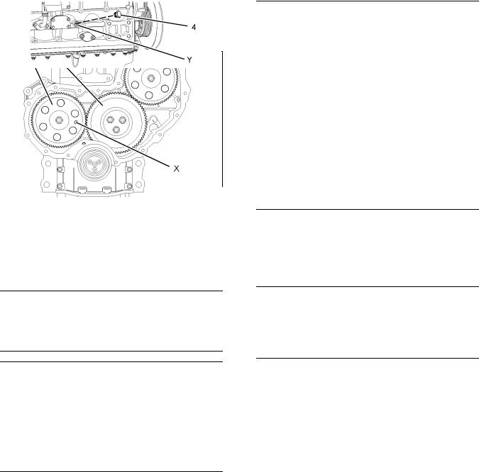
2.Install Tooling (B) through the hole (X) in the camshaft gear (1) into the front housing. Use Tooling (B) in order to lock the camshaft in the correct position.
Illustration 33 |
g01195325 |
|
3.Remove the plug (4) from the cylinder block. Install Tooling (C) into the hole (Y) in the cylinder block. Use Tooling (C) in order to lock the crankshaft in the correct position.
Note: Do not use excessive force to install Tooling
(C). Do not use Tooling (C) to hold the crankshaft during repairs.

SENR9983 |
23 |
|
|
|
Disassembly and Assembly Section |
|
|
|
Illustration 34 |
g01196435 |
|
4.Apply sufficient pressure to the fuel injection pump gear (3) in a counterclockwise direction in order to remove the backlash. Lock the fuel injection pump (5) in this position.
In order to lock the fuel injection pump (5), loosen the locking screw (6) in the fuel injection pump. Slide the spacer (7) into position (Z). Tighten the locking screw (6) against the shaft of the fuel injection pump to a torque of 9 N·m (80 lb in).
Illustration 35 |
g01196142 |
|
|
Alignment of timing marks |
|
5.Mark the gears (1), (2) and (3) in order to show alignment. Refer to Illustration 35.
Note: Identification will ensure that the gears can be installed in the original alignment.
Illustration 36 |
g01196132 |
|
6.Loosen the nut (8) for the fuel pump gear (3).
7.Install Tooling (D) through two opposite holes in the fuel pump gear (3). Tighten Tooling (D) until the fuel pump gear (3) is released.
8.Remove Tooling (D) from the fuel pump gear (3).
9.Remove the nut (8) and washer (not shown) from the fuel pump gear (3). Remove the fuel pump gear.
i02296767
Fuel Injection Pump Gear - Install
Installation Procedure
Table 6
Required Tools
Tool |
Part |
Part Name |
Qty |
|
Number |
||||
|
|
|
||
|
|
|
|
|
B |
27610212 |
Camshaft Timing Pin |
1 |
|
|
|
|
|
|
C |
27610286 |
Crankshaft Timing Pin |
1 |
|
|
|
|
|
NOTICE
Keep all parts clean from contaminants.
Contaminants may cause rapid wear and shortened component life.
Note: The fuel injection pump must remain locked until the procedure instructs you to unlock the fuel injection pump.
1.Ensure that number one piston is at top dead center on the compression stroke. Refer to the Testing and Adjusting Manual, “Finding Top Center for No. 1 Piston”.

24 |
SENR9983 |
Disassembly and Assembly Section |
|
Illustration 37 |
g01195325 |
|
2.Ensure that Tooling (C) is installed in hole (Y) in the cylinder block. Use Tooling (C) in order to lock the crankshaft in the correct position.
Illustration 38 |
g01196475 |
|
3.Ensure that Tooling (B) is installed into the hole
(X)in the camshaft gear (1).
4.Ensure that the shaft (9) of the fuel injection pump is clean and free from damage.
5.Ensure that the fuel injection pump is locked in the correct position. Refer to Disassembly and Assembly Manual, “Fuel Injection Pump - Install”.
6.Ensure that the fuel pump gear is clean and free from wear of damage. If necessary, replace the fuel pump gear.
Illustration 39 |
g01194949 |
|
|
Alignment of timing marks |
|
7.Install the fuel pump gear (3) to the shaft (9) of the fuel injection pump. Ensure that the timing marks on the gears (2) and (3) are in alignment and that the mesh of the gears is correct.
Illustration 40 |
g01196488 |
|
|
Typical example |
|
|
|
Illustration 41 |
g01196435 |
|
8.Install a new spring washer (10) and install the nut (8) to the shaft (9) of the fuel injection pump. Apply sufficient pressure to the fuel injection pump gear (3) in a counterclockwise direction in order to remove the backlash. Tighten the nut (8) to a torque of 25 N·m (18 lb ft). Unlock the fuel injection pump (5).
In order to unlock the fuel injection pump (5), loosen the locking screw (5) in the fuel injection pump. Slide the spacer (7) into position (Z1). Tighten the locking screw (6) against the spacer to a torque of 9 N·m (80 lb in). This will prevent the locking screw from tightening against the shaft of the fuel injection pump.
SENR9983 |
25 |
|
Disassembly and Assembly Section |
9.Remove Tooling (B) and (C). Install the plug
(4)into hole (Y) in the cylinder block. Refer to Illustration 37.
10.Tighten the nut (8) to a torque of 90 N·m (66.4 lb ft).
Illustration 42 |
g00944084 |
|
|
Checking backlash |
|
11.Ensure that the backlash for the gears (2) and (3) is within specified values. Refer to the Specifications Manual, “Gear Group (Front)” for further information.
12.Lubricate the teeth of the gears with clean engine oil.
End By:
a.Install the front cover. Refer to Disassembly and Assembly Manual, “Front Cover - Remove and Install”.
i02295935
Electronic Unit Injector - Remove
Removal Procedure (One Injector)
Table 7
Required Tools
Tool |
Part Number |
Part Description |
Qty |
|
|
|
|
A |
21825576 |
Engine Turning Tool |
1 |
|
|
|
|
B |
- |
T40 Torx Socket |
1 |
|
|
|
|
C |
27610288 |
Pry Bar |
1 |
|
|
|
|
Start By:
a.Remove the valve mechanism cover. Refer to Disassembly and Assembly Manual, “Valve Mechanism Cover - Remove and Install”.
Contact with high pressure fuel may cause fluid penetration and burn hazards. High pressure fuel spray may cause a fire hazard. Failure to follow these inspection, maintenance and service instructions may cause personal injury or death.
NOTICE
Ensure that all adjustments and repairs that are carried out to the fuel system are performed by authorised personnel that have the correct training.
Before begining ANY work on the fuel system, refer to Operation and Maintenance Manual, “General Hazard Information and High Pressure Fuel Lines” for safety information.
Refer to Testing and Adjusting Manual, “Cleanliness of Fuel System Components” for detailed information on the standards of cleanliness that must be observed during ALL work on the fuel system.
1. Isolate the fuel supply to the engine.
Illustration 43 |
g01193285 |
|
|
Typical example |
|
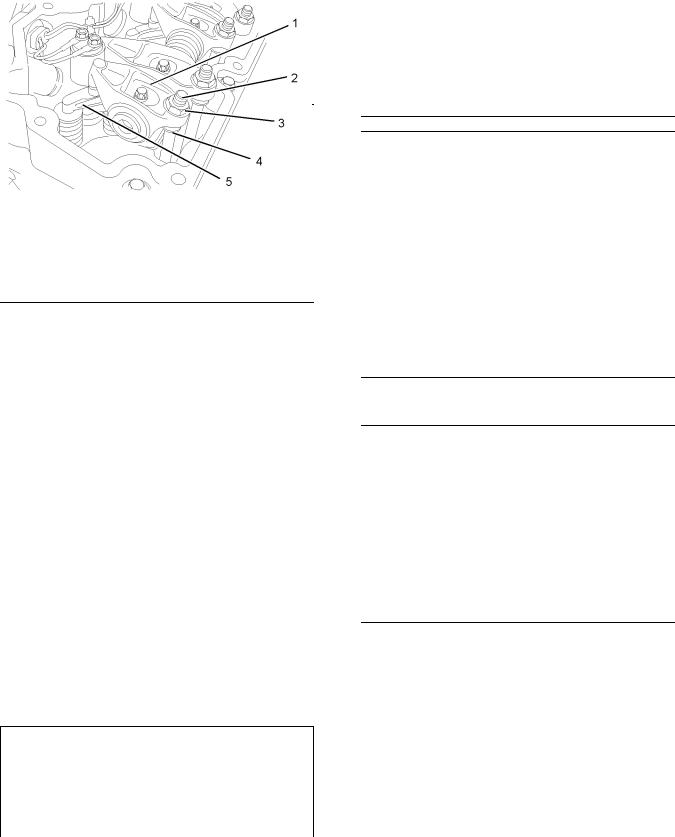
2.Use Tooling (A) in order to rotate the crankshaft until the rocker arms (1) for the appropriate cylinder are in the correct position in order to adjust the valve lash. Refer to Testing and Adjusting Manual, “Engine Valve Lash - Inspect/Adjust”.
3.Follow Steps 3.a through 3.c in order to gain access to the assembly of the electronic unit injector.
a.Loosen the nuts (3) on the appropriate cylinder. Unscrew the adjusters (2) on the appropriate cylinder until the pushrods (4) can be withdrawn from the balls of the adjusters.
b.Withdraw the cups of the pushrods (4) from the balls of the adjusters (2).
26 |
SENR9983 |
Disassembly and Assembly Section |
|
c.Make a temporary mark on the valve bridges
(5) in order to show the location and orientation. Remove valve bridges from the cylinder head.
Note: Identification will ensure that the valve bridges can be reinstalled in the original location and the original orientation. Do not interchange the location or the orientation of used valve bridges.
4.Place a suitable container below the fuel transfer pump in order to catch any fuel that might be spilled.
Note: Clean up any spillage of fuel immediately.
6.Remove the fuel injection line (not shown) and the seal (7) from the appropriate electronic unit injector (10). Refer to Disassembly and Assembly Manual, “Fuel Injecton Lines - Remove”.
Note: Cap all open ports immediately with new caps.
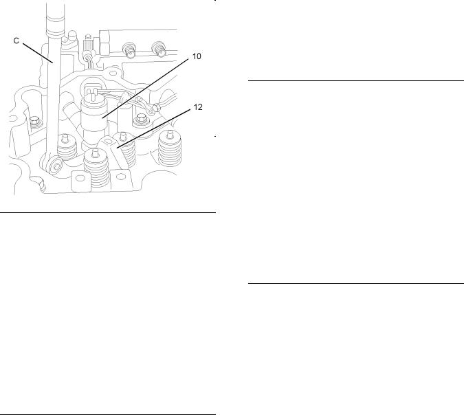
7.Place a temporary identification mark on the connections (9) for the harness assembly (8).
8.Use a deep socket to remove the connections (9) from the electronic unit injectors (10).
9.Slide the rocker arms (1) to one side in order to gain access to the torx screw (11). Use Tooling (B) in order to remove the torx screw from the clamp (12). Discard the torx screw.
10.Place a temporary identification mark on the electronic unit injector (10). The electronic unit injector must be reinstalled in the original location in the cylinder head.
Illustration 44 |
g01193839 |
|
|
Typical example |
|
5.Disconnect the tube assembly (6) for the injector leak-off from the fuel transfer pump. Allow the fuel to drain from the tube assembly.
Illustration 45 |
g01193293 |
|
|
The rocker shaft is not shown for clarity. |
|
Illustration 46 |
g01193295 |
|
|
The rocker shaft is not shown for clarity. |
|
11.Use Tooling (C) to pry beneath the clamp (12) and free the electronic unit injector (10) from the cylinder head.
12.Remove the electronic unit injector (10) and the clamp (12) from the cylinder head.

SENR9983 |
27 |
|
Disassembly and Assembly Section |
Illustration 47 |
g01193297 |
|
13.Remove the sealing washer (13) from the base of the electronic unit injector (10) or from the bore in the cylinder head. Discard the sealing washer.
14.Remove the O-ring seal (14) from the electronic unit injector (10). Discard the O-ring seal.
Removal Procedure (All Injectors)
Table 8
Required Tools
Tool |
Part Number |
Part Description |
Qty |
|
|
|
|
B |
- |
T40 Torx Socket |
1 |
|
|
|
|
C |
27610288 |
Pry Bar |
1 |
|
|
|
|
Start By:
a.Remove the rocker shaft assembly. Refer to Disassembly and Assembly Manual, “Rocker Shaft - Remove”.
b.Remove the fuel injection lines. Refer to Disassembly and Assembly Manual, “Fuel Injecton Lines - Remove”.
Contact with high pressure fuel may cause fluid penetration and burn hazards. High pressure fuel spray may cause a fire hazard. Failure to follow these inspection, maintenance and service instructions may cause personal injury or death.
NOTICE
Ensure that all adjustments and repairs that are carried out to the fuel system are performed by authorised personnel that have the correct training.
Before begining ANY work on the fuel system, refer to Operation and Maintenance Manual, “General Hazard Information and High Pressure Fuel Lines” for safety information.
Refer to Testing and Adjusting Manual, “Cleanliness of Fuel System Components” for detailed information on the standards of cleanliness that must be observed during ALL work on the fuel system.
1.Isolate the fuel supply to the engine.
2.Place a suitable container below the fuel transfer pump in order to catch any fuel that might be spilled.
Note: Clean up any spillage of fuel immediately.
Illustration 48 |
g01193839 |
|
|
Typical example |
|
3.Disconnect the tube assembly (6) for the injector leak-off from the fuel transfer pump. Allow the fuel to drain from the tube assembly.
28 |
SENR9983 |
Disassembly and Assembly Section |
|
8. Use Tooling (C) to pry beneath the clamp (12) and free the electronic unit injector (8) from the cylinder head.
9. Remove the electronic unit injector (10) and the clamp (12) from the cylinder head.
Illustration 49 |
g01193293 |
|
4.Place a temporary identification mark on the connections (9) for the harness assembly (8).
5.Use a deep socket to remove the connections (9) from the electronic unit injectors (10).
6.Use Tooling (B) in order to remove the torx screw (11) from the clamp (12). Discard the torx screw.
7.Place a temporary identification mark on the electronic unit injector (10). The electronic unit injector must be reinstalled in the original location in the cylinder head.
Illustration 51 |
g01193297 |
|
10.Remove the sealing washer (13) from the base of the electronic unit injector (10) or from the bore in the cylinder head. Discard the sealing washer.
11.Remove the O-ring seal (14) from the electronic unit injector (8). Discard the O-ring seal.
12.Repeat Steps 4 through 11 in order to remove the remaining electronic unit injectors.
i02295941
Electronic Unit Injector - Install
Installation Procedure (One
Injector)
Table 9
Required Tools
Tool |
Part |
Part Description |
Qty |
|
|
Number |
|
|
|
|
|
|
|
|
B |
- |
T40 Torx Socket |
1 |
|
|
|
|
|
|
|
- |
Vacuum Pump |
1 |
|
D |
|
|
|
|
- |
Tube |
1 |
||
|
||||
|
7.9 mm (0.31 inch) OD |
|||
|
|
|
||
|
|
|
|
|
E |
27610294 |
Injector Pipe Nut Tool |
1 |
|
|
|
|
|
|
F |
27610296 |
Torque Wrench |
1 |
|
|
|
|
|
Illustration 50 |
g01193295 |
|
SENR9983 |
29 |
|
Disassembly and Assembly Section |
NOTICE
Ensure that all adjustments and repairs that are carried out to the fuel system are performed by authorised personnel that have the correct training.
Before begining ANY work on the fuel system, refer to Operation and Maintenance Manual, “General Hazard Information and High Pressure Fuel Lines” for safety information.
Refer to Testing and Adjusting Manual, “Cleanliness of Fuel System Components” for detailed information on the standards of cleanliness that must be observed during ALL work on the fuel system.
Illustration 53 |
g01193297 |
|
4.Install a new O-ring seal (14) to the electronic unit injector (10).
Note: Do not lubricate the O-ring seal.
5.Ensure that the seat for the electronic unit injector in the cylinder head is clean and free from damage. Position a new sealing washer (13) onto the seat for the electronic unit injector in the cylinder head.
Illustration 52 |
g01194240 |
|
|
The location of the calibration code |
|
1.If a replacement electronic unit injector is installed, the calibration code that is located at position (X) must be programmed into the electronic control module. Refer to Troubleshooting Guide, “Injector Trim File” for more information.
2.Use Tooling (D) in order to remove any fuel from the cylinder.
Note: Evacuate as much fuel as possible from the cylinder before installing the electronic unit injector.
3.Ensure that the fuel inlet port of the electronic unit injector is capped. Ensure that the electronic unit injector is clean.
Illustration 54 |
g01193293 |
|
|
The rocker shaft is not shown for clarity. |
|
6.Install the clamp (12) to the electronic unit injector (10). Install the electronic unit injector assembly into the cylinder head.
Note: Ensure that the electronic unit injector is pushed firmly against the seat in the cylinder head.
7.Install a new torx screw (11) to the clamp (12). Tighten the torx screw finger tight.
8.Thoroughly clean the seal (7). Inspect the seal for damage. If necessary, replace the seal.

30 |
SENR9983 |
Disassembly and Assembly Section |
|
Note: The seal can be damaged by contact with fuel.
9.Remove the cap from the electronic unit injector (10). Install the seal (7) to the electronic unit injector (10). Ensure that the flange on the seal is flush with the valve mechanism cover base.
10.Remove the plugs from the new fuel injection line. Loosely install the fuel injection line (not shown). Refer to Disassembly and Assembly Manual, “Fuel Injecton Lines - Install”.
Note: Ensure that the ends of the fuel injection line are seated in the electronic unit injector and the fuel manifold. Tighten the nuts finger tight.
11.Use Tooling (B) to tighten the torx screw (11) to a torque of 27 N·m (20 lb ft).
12.Use Tooling (E) to tighten the fuel injection line (not shown) to a torque of 30 N·m (22 lb ft). Refer to Disassembly and Assembly Manual, “Fuel Injecton Lines - Install”.
13.Use a deep socket to install the harness assembly
(8)to the electronic unit injector (10). Use Tooling
(F) to tighten the connections to a torque of 2.4 N·m (21 lb in).
Illustration 55 |
g01193285 |
|
|
Typical example |
|
14. Install bridges (5) to the cylinder head.
Note: Ensure that used valve bridges are reinstalled in the original location and the original orientation. Do not interchange the location or the orientation of used valve bridges.
15. Ensure that the bottoms of the pushrod are seated in the cups of the valve lifters. Locate the balls of the adjusters (2) into the cups of the pushrods (4). Adjust the valve lash. Refer to
Testing and Adjusting Manual, “Engine Valve Lash - Inspect/Adjust”.
Illustration 56 |
g01193839 |
|
|
Typical example |
|
16.Connect the tube assembly (6) for the injector leak-off to the fuel transfer pump.
17.Restore the fuel supply to the engine.
18.Remove the air from the fuel system. Refer to Operation and Maintenance Manual, “Fuel System - Prime” for more information.
End By:
a.Install the valve mechanism cover. Refer to Disassembly and Assembly Manual, “Valve Mechanism Cover - Remove and Install”.
Installation Procedure (All
Injectors)
Table 10
Required Tools
Tool |
Part |
Part Description |
Qty |
|
Number |
|
|
|
|
|
|
B |
- |
T40 Torx Socket |
1 |
|
|
|
|
|
- |
Vacuum Pump |
1 |
D |
|
|
|
- |
Tube |
1 |
|
|
7.9 mm (0.31 inch) OD |
||
|
|
|
|
|
|
|
|
E |
27610294 |
Injector Pipe Nut Tool |
1 |
|
|
|
|
F |
27610296 |
Torque Wrench |
1 |
|
|
|
|
 Loading...