


 Loading...
PERKINS TIER 2 DIESEL
ENGINES
1100 (VK)
H8.00-12.00XM (H170-280HD) [F007, G007];
H13.00-16.00XM (H300-360HD) [E019, F019]; H10.00-12.00XM-12EC (H360HD-EC) [E019, F019]
PART NO. 1541323 |
|
600 SRM 1068 |
|

SAFETY PRECAUTIONS
MAINTENANCE AND REPAIR
•When lifting parts or assemblies, make sure all slings, chains, or cables are correctly fastened, and that the load being lifted is balanced. Make sure the crane, cables, and chains have the capacity to support the weight of the load.
•Do not lift heavy parts by hand, use a lifting mechanism.
•Wear safety glasses.
•DISCONNECT THE BATTERY CONNECTOR before doing any maintenance or repair on electric lift trucks. Disconnect the battery ground cable on internal combustion lift trucks.
•Always use correct blocks to prevent the unit from rolling or falling. See HOW TO PUT THE LIFT TRUCK ON BLOCKS in the Operating Manual or the Periodic Maintenance section.
•Keep the unit clean and the working area clean and orderly.
•Use the correct tools for the job.
•Keep the tools clean and in good condition.
•Always use HYSTER APPROVED parts when making repairs. Replacement parts must meet or exceed the specifications of the original equipment manufacturer.
•Make sure all nuts, bolts, snap rings, and other fastening devices are removed before using force to remove parts.
•Always fasten a DO NOT OPERATE tag to the controls of the unit when making repairs, or if the unit needs repairs.
•Be sure to follow the WARNING and CAUTION notes in the instructions.
•Gasoline, Liquid Petroleum Gas (LPG), Compressed Natural Gas (CNG), and Diesel fuel are flammable. Be sure to follow the necessary safety precautions when handling these fuels and when working on these fuel systems.
•Batteries generate flammable gas when they are being charged. Keep fire and sparks away from the area. Make sure the area is well ventilated.
NOTE: The following symbols and words indicate safety information in this manual:
 WARNING
Indicates a condition that can cause immediate death or injury!
CAUTION
Indicates a condition that can cause property damage!
Perkins Tier 2 Diesel Engines |
Table of Contents |
TABLE OF CONTENTS |
|
General ................................................................................................................................................................. |
1 |
General Safety Rules....................................................................................................................................... |
1 |
Description ........................................................................................................................................................... |
2 |
Engine Serial Number Codes.......................................................................................................................... |
4 |
Engine Data ..................................................................................................................................................... |
4 |
Engine Removal and Installation ....................................................................................................................... |
5 |
Cylinder Head Assembly Repair ......................................................................................................................... |
5 |
Valve Cover ...................................................................................................................................................... |
5 |
Remove......................................................................................................................................................... |
5 |
Install........................................................................................................................................................... |
6 |
Rocker Arm Assembly ..................................................................................................................................... |
6 |
Remove......................................................................................................................................................... |
6 |
Disassemble ................................................................................................................................................. |
6 |
Inspect.......................................................................................................................................................... |
6 |
Assemble ...................................................................................................................................................... |
6 |
Install........................................................................................................................................................... |
6 |
Valve Clearance Adjustments ......................................................................................................................... |
7 |
Valve Springs ................................................................................................................................................... |
8 |
Cylinder Head Assembly................................................................................................................................. |
9 |
Remove......................................................................................................................................................... |
9 |
Install......................................................................................................................................................... |
11 |
Valves and Valve Springs .............................................................................................................................. |
14 |
Remove....................................................................................................................................................... |
14 |
Inspect........................................................................................................................................................ |
14 |
Install......................................................................................................................................................... |
15 |
Valve Guides .................................................................................................................................................. |
15 |
Inspect........................................................................................................................................................ |
15 |
Remove....................................................................................................................................................... |
15 |
Install......................................................................................................................................................... |
15 |
Cylinder Head and Valve Seats .................................................................................................................... |
16 |
Inspect........................................................................................................................................................ |
16 |
Repair......................................................................................................................................................... |
17 |
New Valve Seats, Install ........................................................................................................................... |
17 |
Piston and Connecting Rod Assemblies Repair ............................................................................................... |
17 |
Rod Bearings.................................................................................................................................................. |
18 |
Remove....................................................................................................................................................... |
18 |
Install......................................................................................................................................................... |
18 |
Piston and Connecting Rod Assembly .......................................................................................................... |
19 |
Service Note............................................................................................................................................... |
19 |
Remove....................................................................................................................................................... |
19 |
Install......................................................................................................................................................... |
20 |
Piston Rings ................................................................................................................................................... |
21 |
Remove....................................................................................................................................................... |
21 |
Inspect........................................................................................................................................................ |
21 |
Install......................................................................................................................................................... |
22 |
Piston and Connecting Rod ........................................................................................................................... |
22 |
Disassemble ............................................................................................................................................... |
22 |
Inspect........................................................................................................................................................ |
22 |
How to Select Correct Replacements ....................................................................................................... |
23 |
Install......................................................................................................................................................... |
24 |
Piston Cooling Jets ........................................................................................................................................ |
24 |
©2004 HYSTER COMPANY |
i |
Table of Contents |
Perkins Tier 2 Diesel Engines |
TABLE OF CONTENTS (Continued) |
|
Remove....................................................................................................................................................... |
24 |
Install......................................................................................................................................................... |
25 |
Crankshaft Assembly Repair ............................................................................................................................ |
25 |
General........................................................................................................................................................... |
25 |
Crankshaft Pulley.......................................................................................................................................... |
26 |
Remove....................................................................................................................................................... |
26 |
Inspect........................................................................................................................................................ |
26 |
Install......................................................................................................................................................... |
26 |
Rear Oil Seal .................................................................................................................................................. |
27 |
Remove....................................................................................................................................................... |
27 |
Install......................................................................................................................................................... |
27 |
Main Bearings................................................................................................................................................ |
28 |
Remove....................................................................................................................................................... |
28 |
Inspect........................................................................................................................................................ |
29 |
Install......................................................................................................................................................... |
29 |
Thrust Washers.............................................................................................................................................. |
29 |
Crankshaft Axial Movement, Check ........................................................................................................ |
29 |
Remove....................................................................................................................................................... |
30 |
Install......................................................................................................................................................... |
30 |
Crankshaft ..................................................................................................................................................... |
31 |
Remove....................................................................................................................................................... |
31 |
Inspect........................................................................................................................................................ |
31 |
Install......................................................................................................................................................... |
32 |
Flywheel ......................................................................................................................................................... |
33 |
Remove....................................................................................................................................................... |
33 |
Ring Gear, Replace .................................................................................................................................... |
33 |
Install......................................................................................................................................................... |
33 |
Flywheel Housing .......................................................................................................................................... |
34 |
Remove....................................................................................................................................................... |
34 |
Install......................................................................................................................................................... |
34 |
Timing Case and Timing Gears Repair ............................................................................................................ |
35 |
General........................................................................................................................................................... |
35 |
Timing Case Cover ........................................................................................................................................ |
35 |
Remove....................................................................................................................................................... |
35 |
Install......................................................................................................................................................... |
36 |
Front Oil Seal................................................................................................................................................. |
36 |
Remove....................................................................................................................................................... |
36 |
Install......................................................................................................................................................... |
36 |
Crankshaft Pulley Wear Sleeve .................................................................................................................... |
37 |
Install......................................................................................................................................................... |
37 |
Idler Gear and Hub ....................................................................................................................................... |
37 |
Remove....................................................................................................................................................... |
37 |
Install......................................................................................................................................................... |
38 |
Air Compressor Drive, Bendix ...................................................................................................................... |
39 |
Disassemble ............................................................................................................................................... |
39 |
Assemble .................................................................................................................................................... |
39 |
Fuel Injection Pump Gear ............................................................................................................................. |
40 |
Remove....................................................................................................................................................... |
40 |
Install......................................................................................................................................................... |
41 |
Camshaft Gear............................................................................................................................................... |
41 |
Remove....................................................................................................................................................... |
41 |
ii

Perkins Tier 2 Diesel Engines |
Table of Contents |
TABLE OF CONTENTS (Continued) |
|
Install......................................................................................................................................................... |
42 |
Crankshaft Gear ............................................................................................................................................ |
42 |
Remove....................................................................................................................................................... |
42 |
Install......................................................................................................................................................... |
43 |
Timing Case ................................................................................................................................................... |
43 |
Remove....................................................................................................................................................... |
43 |
Install......................................................................................................................................................... |
43 |
Camshaft and Tappets .................................................................................................................................. |
44 |
Remove....................................................................................................................................................... |
44 |
Install......................................................................................................................................................... |
45 |
Cylinder Block Assembly Repair....................................................................................................................... |
45 |
Description ..................................................................................................................................................... |
45 |
Cylinder Block ............................................................................................................................................... |
45 |
Disassemble ............................................................................................................................................... |
45 |
Inspect........................................................................................................................................................ |
46 |
Assemble .................................................................................................................................................... |
46 |
Cylinder Liner................................................................................................................................................ |
47 |
Inspect........................................................................................................................................................ |
47 |
Cylinder Liner Condition, Check.............................................................................................................. |
47 |
Remove....................................................................................................................................................... |
48 |
Service Liner, Install................................................................................................................................. |
49 |
Partially Finished Liner, Install............................................................................................................... |
50 |
Engine Timing.................................................................................................................................................... |
51 |
Description ..................................................................................................................................................... |
51 |
How to Set Number One Piston to TDC on Compression Stroke ........................................................... |
52 |
How to Set Number One Piston to TDC on Compression Stroke (Alternate Procedure)...................... |
53 |
How to Set Number One Piston to 4 After TDC on Compression Stroke ............................................. |
54 |
Valve Timing, Check.................................................................................................................................. |
55 |
Fuel Injection Pump Timing, Check......................................................................................................... |
56 |
Turbocharger ...................................................................................................................................................... |
56 |
General........................................................................................................................................................... |
56 |
Remove ........................................................................................................................................................... |
56 |
Install ............................................................................................................................................................. |
57 |
Impeller and Compressor Housing, Clean ................................................................................................... |
57 |
Waste-Gate Valve Check ............................................................................................................................... |
58 |
Closed Circuit Breather System (CCB) ........................................................................................................ |
59 |
CCB Assembly, Remove ............................................................................................................................ |
59 |
Closed Circuit Drain Valve, Remove ........................................................................................................ |
59 |
CCB Assembly, Install .............................................................................................................................. |
59 |
Closed Circuit Drain Valve, Install .......................................................................................................... |
59 |
Lubrication System Repair................................................................................................................................ |
60 |
General........................................................................................................................................................... |
60 |
Oil Filter, Replace .......................................................................................................................................... |
60 |
Oil Filter Head............................................................................................................................................... |
60 |
Remove....................................................................................................................................................... |
60 |
Install......................................................................................................................................................... |
60 |
Oil Filter Head Bypass Valve........................................................................................................................ |
61 |
Remove and Install ................................................................................................................................... |
61 |
Oil Sump ........................................................................................................................................................ |
61 |
Remove....................................................................................................................................................... |
61 |
Install......................................................................................................................................................... |
61 |
iii
Table of Contents |
Perkins Tier 2 Diesel Engines |
TABLE OF CONTENTS (Continued) |
|
Oil Pump ........................................................................................................................................................ |
62 |
Remove....................................................................................................................................................... |
62 |
Inspect........................................................................................................................................................ |
62 |
Install......................................................................................................................................................... |
63 |
Relief Valve .................................................................................................................................................... |
64 |
Remove....................................................................................................................................................... |
64 |
Disassemble ............................................................................................................................................... |
64 |
Inspect........................................................................................................................................................ |
64 |
Assemble .................................................................................................................................................... |
64 |
Install......................................................................................................................................................... |
64 |
Idler Gear Shaft, Replace.............................................................................................................................. |
64 |
Remove....................................................................................................................................................... |
65 |
Remove (Alternative) ................................................................................................................................ |
65 |
Install......................................................................................................................................................... |
66 |
Install (Alternative) .................................................................................................................................. |
66 |
Fuel System Repair............................................................................................................................................ |
67 |
Description ..................................................................................................................................................... |
67 |
Fuel Injection Pump ...................................................................................................................................... |
69 |
Remove....................................................................................................................................................... |
69 |
Install......................................................................................................................................................... |
71 |
Fuel System Air Removal.............................................................................................................................. |
72 |
Fuel Filter, Replace ....................................................................................................................................... |
74 |
Fuel Injectors ................................................................................................................................................. |
74 |
Remove....................................................................................................................................................... |
75 |
Inspect........................................................................................................................................................ |
75 |
Install......................................................................................................................................................... |
75 |
Fuel Lift Pump............................................................................................................................................... |
76 |
Remove....................................................................................................................................................... |
76 |
Disassemble ............................................................................................................................................... |
76 |
Assemble .................................................................................................................................................... |
76 |
Install......................................................................................................................................................... |
77 |
Test............................................................................................................................................................. |
77 |
Cooling System Repair ...................................................................................................................................... |
78 |
General........................................................................................................................................................... |
78 |
Thermostat..................................................................................................................................................... |
78 |
Remove....................................................................................................................................................... |
78 |
Install......................................................................................................................................................... |
79 |
Test............................................................................................................................................................. |
79 |
Coolant Pump ................................................................................................................................................ |
79 |
Remove....................................................................................................................................................... |
79 |
Disassemble ............................................................................................................................................... |
80 |
Assemble .................................................................................................................................................... |
82 |
Install......................................................................................................................................................... |
84 |
Fan and Fan Drive ........................................................................................................................................ |
85 |
Remove....................................................................................................................................................... |
85 |
Install......................................................................................................................................................... |
85 |
Oil Cooler ....................................................................................................................................................... |
85 |
Remove....................................................................................................................................................... |
85 |
Disassemble and Assemble....................................................................................................................... |
86 |
Install......................................................................................................................................................... |
86 |
Electrical Equipment Repair............................................................................................................................. |
87 |
iv
Perkins Tier 2 Diesel Engines |
Table of Contents |
TABLE OF CONTENTS (Continued) |
|
Drive Belts ..................................................................................................................................................... |
87 |
Alternator....................................................................................................................................................... |
87 |
Remove....................................................................................................................................................... |
87 |
Install......................................................................................................................................................... |
87 |
Electronic Control Module (ECM) ................................................................................................................ |
88 |
Remove....................................................................................................................................................... |
88 |
Inspect........................................................................................................................................................ |
88 |
Install......................................................................................................................................................... |
88 |
Voltage Load and Protection Module (VLPM).............................................................................................. |
89 |
Remove....................................................................................................................................................... |
89 |
Install......................................................................................................................................................... |
89 |
Engine Speed and Timing Sensor................................................................................................................. |
89 |
Remove....................................................................................................................................................... |
89 |
Install......................................................................................................................................................... |
90 |
Pressure Sensors (Engine Oil and Air Intake)............................................................................................. |
90 |
Remove....................................................................................................................................................... |
90 |
Install......................................................................................................................................................... |
91 |
Temperature Sensor ...................................................................................................................................... |
91 |
Remove....................................................................................................................................................... |
91 |
Install......................................................................................................................................................... |
92 |
Starter Motor ................................................................................................................................................. |
92 |
Remove....................................................................................................................................................... |
92 |
Install......................................................................................................................................................... |
92 |
Cold Start Aid ................................................................................................................................................ |
92 |
Air Compressor .................................................................................................................................................. |
92 |
General........................................................................................................................................................... |
92 |
Repair ............................................................................................................................................................. |
93 |
Remove....................................................................................................................................................... |
93 |
Install......................................................................................................................................................... |
93 |
Rotary Exhauster Replacement ........................................................................................................................ |
94 |
Remove ........................................................................................................................................................... |
94 |
Clean .............................................................................................................................................................. |
94 |
Install ............................................................................................................................................................. |
94 |
Engine Specifications......................................................................................................................................... |
95 |
Cylinder Head Assembly............................................................................................................................... |
95 |
Piston and Connecting Rods ......................................................................................................................... |
98 |
Crankshaft Assembly .................................................................................................................................... |
99 |
Crankshaft Overhaul .............................................................................................................................. |
100 |
Timing Case and Drive Assembly............................................................................................................... |
102 |
Engine Block Assembly ............................................................................................................................... |
103 |
Turbocharger................................................................................................................................................ |
104 |
Lubrication System ..................................................................................................................................... |
105 |
Cooling System ............................................................................................................................................ |
107 |
Flywheel and Housing................................................................................................................................. |
107 |
Electrical Equipment................................................................................................................................... |
107 |
Torque Specifications ....................................................................................................................................... |
108 |
Cylinder Head Assembly............................................................................................................................. |
108 |
Piston and Connecting Rod Assemblies ..................................................................................................... |
108 |
Crankshaft Assembly .................................................................................................................................. |
108 |
Timing Case and Drive Assembly............................................................................................................... |
108 |
Turbocharger................................................................................................................................................ |
108 |
v

Table of Contents |
Perkins Tier 2 Diesel Engines |
TABLE OF CONTENTS (Continued) |
|
Lubrication System ..................................................................................................................................... |
108 |
Fuel System ................................................................................................................................................. |
108 |
Cooling System ............................................................................................................................................ |
109 |
Flywheel ....................................................................................................................................................... |
109 |
Auxiliary Equipment................................................................................................................................... |
109 |
Special Torque Specifications .......................................................................................................................... |
109 |
Flywheel and Housing................................................................................................................................. |
109 |
Electrical Equipment................................................................................................................................... |
109 |
Auxiliary Equipment................................................................................................................................... |
109 |
Special Tools ..................................................................................................................................................... |
110 |
Troubleshooting................................................................................................................................................ |
115 |
Turbocharger Troubleshooting ........................................................................................................................ |
117 |
This section is for the following models:
H8.00-12.00XM (H170-280HD) [F007, G007];
H13.00-16.00XM (H300-360HD) [E019, F019];
H10.00-12.00XM-12EC (H360HD-EC) [E019, F019]
vi
600 SRM 1068 |
General |
General
This section has the description and repair instructions for the VK model of the Series 1100 Perkins diesel engine. All VK models are six-cylinder, turbocharged.
GENERAL SAFETY RULES
 WARNING
Some seals used in this engine are made of synthetic materials called fluoroelastomers
(a commercial name is Viton). These fluoroelastomers can decompose at temperatures greater than 316 C (600
 F) or by burning and cause hydrofluoric acid to form on the surface of the seal or nearby equipment.
Do not touch gaskets, seals, or O-rings which appear charred or black and sticky after exposure to temperatures greater than 316 C (600
 F) or burning. Contact with this acid can cause severe burns of the skin and eyes. Burns can be delayed several hours after contact.
Do the following procedures to prevent exposure to hydrofluoric acid:
•Wear disposable neoprene or PVC gloves and discard the gloves after use.
•Wash the area with 10 percent calcium hydroxide solution to neutralize any acid and then clean with water.
If burned seal by-product touches the skin or eyes:
•Immediately flush with water for a minimum of 15 minutes.
•Apply 2.5 percent calcium gluconate gel to affected area of skin.
•Get medical help immediately for suspected hydrogen fluoride or hydrofluoric acid burn.
 WARNING
Disconnect the battery cables before doing any disassembly and repair of the engine or parts of the electrical system. Put a DO NOT OPERATE tag in the operator’s area and on the battery connectors.
Long-term exposure to used engine oil can cause skin irritation or cancer. Wash with detergent and water.
Exhaust from internal combustion engines contains carbon monoxide and other harmful chemicals. Carbon monoxide is a colorless, odorless poison and can cause unconsciousness or death without warning. Long-term exposure to exhaust or chemicals in the exhaust can cause cancer, birth defects, and other reproductive harm. Avoid exposure to engine exhaust.
Do not use diesel engines indoors where soot can accumulate.
If engines are operated in confined spaces, maintain adequate ventilation or vent exhaust to the outside. Do not exceed applicable air contaminant limits.
Follow the inspection and maintenance schedule and procedures in this manual. Do not alter exhaust, ignition, or fuel systems.
 CAUTION
Disposal of lubricants and fluids must meet local environmental regulations.
Disposal of batteries must meet local environmental regulations.
The diodes and resistors in the electrical system can be damaged if the following cautions are not followed:
•Do not disconnect the battery when the engine is running. The voltage surge can damage the diodes and resistors.
•Do not disconnect an electric wire before the engine is stopped and the switches are OFF.
•Do not cause a short circuit by connection of the electric wires to the wrong terminals. Make sure a correct identification is made of the wire before it is connected.
•Verify the battery is the correct voltage and polarity before it is connected.
•Do not check for current flow by making a spark because the electronic components can be damaged.
1
Description
 CAUTION
When setscrews or studs are fitted into holes which are tapped through the cylinder block, a suitable sealant must be used to prevent leakage.
Micro encapsulated anaerobic sealant (M.E.A.S.) fasteners have been introduced instead of jointing compounds or other sealants when the fasteners are fitted in through holes into oil or coolant passages. The identification of these fasteners, as supplied, is by a red, blue, or other color sealant around the fastener threads.
600 SRM 1068
With M.E.A.S. sealed studs, the sealed end must be fitted into the cylinder head/cylinder block, etc. Ensure that the threaded holes have a 1.59 mm (0.0626 in.), 45 chamfer so that the M.E.A.S. sealant is not removed. If the fasteners have to be removed and fitted again, the threads must be cleaned and a suitable sealant used.
Observe the previous WARNINGS and CAUTIONS before repairing any equipment.
Description
The cylinder head is cast iron and has one inlet valve and one exhaust valve for each cylinder. The valve seats and the valve guides are replaceable. The fuel injectors are in the cylinder head. The overhead valve assembly is actuated by a camshaft inside of the engine block. A gear train, turned by the crankshaft, turns the camshaft, coolant pump, injection pump, and a power-takeoff (PTO) which is available for additional equipment. The hydraulic pump for the steering function or a compressor is normally turned by the PTO. The fuel pump is actuated by the camshaft. See Figure 1.
The crankshaft has seven main bearings. The main bearing in the center of the crankshaft is the thrust bearing and has thrust washers on both sides of the bearing.
The cylinder block is cast iron and has cylinder liners that can be replaced during overhaul.
A Fastram™ combustion chamber in the top of each piston is designed to give an efficient mix of fuel and
air. Each piston has three piston rings (two compression rings and an oil control ring). The top compression ring has a special insert for the groove, to reduce wear. Axial location of the fully floating piston pin is by circlips. The piston pin is off-center to reduce the noise level. A jet for cooling oil to the bottom of the piston is installed.
The cooling fan and the alternator are turned by a drive belt. The cooling fan is not connected to the coolant pump. The coolant pump is turned by the gear for the fuel injection pump in the timing gear case.
The timing, speed adjustment, and quantity of fuel sent to the fuel injectors is controlled electronically by the Electronic Control Module (ECM).
A Bosch VP30 series fuel injection pump is used on all 1100 VK engines. Special tools are needed to repair an injection pump, and they are normally sent to an authorized repair station if repairs are necessary.
2

600 SRM 1068 |
Description |
|
|
|
|
1. |
FILL CAP FOR ENGINE OIL |
8. |
OIL SUMP |
2. |
FUEL FILTER |
9. |
ALTERNATOR |
3. |
FUEL INJECTION PUMP |
10. |
TURBOCHARGER |
4. |
COOLANT PUMP |
11. |
DIPSTICK, ENGINE OIL |
5. |
AIR COMPRESSOR |
12. |
FAN DRIVE |
6. |
VIBRATION DAMPER |
13. |
OIL COOLER |
7. |
OIL FILTERS |
14. |
TIMING CASE |
Figure 1. Engine
3
Description |
600 SRM 1068 |
ENGINE SERIAL NUMBER CODES
The engine number is on a label on the left side of the engine block. See Figure 2.
|
|
|
1. PART NUMBERS |
2. |
ENGINE SERIAL |
FOR FUEL |
|
NUMBER |
INJECTION PUMP |
3. |
EMISSIONS LABEL |
Figure 2. Serial Number Locations
A typical serial number has the following code:
VK |
U |
090001 |
H |
1 |
2 |
3 |
4 |
where:
1 = Type of engine: VK = 1100
2 = Country of manufacture (U = manufactured in the United Kingdom)
3 = Serial number
4 = Year of manufacture. The letter indicates the year of manufacture. The letters I, O, Q, R, and Z are not used.
If parts or service are required for your engine, the complete engine number must be given to your dealer.
ENGINE DATA
The specifications and tolerance details for engine repair are in a chart at the end of this section.
1100 (VK) |
|
Power rating at 2300 |
|
rpm................................... |
129.5 kW (173.7 bhp) |
Number of cylinders........ |
6 |
Firing order ..................... |
1–5–3–6–2–4 |
Bore and stroke ............... |
100 × 127 mm |
|
(3.937 × 5.000 in.) |
Displacement................... |
6.00 liter (366 in.3) |
Compression ratio ........... |
17.25:1 |
Minimum oil pressure |
|
(at maximum speed |
|
and normal operating |
|
temperature) |
|
Governor speed (no |
|
load) ................................. |
280 kPa (41 psi) |
See the Periodic Maintenance section for your model of lift truck.
Idle Speed ........................ |
725 to 775 rpm |
||||||||
Thermostat |
|
|
|
|
|
|
|
|
|
Begin to open |
80 to 84 |
|
C (176 to 183 |
|
F) |
||||
|
|
||||||||
Fully open |
96 |
|
C (205 |
|
F) |
||||
|
|
||||||||
Valve clearance (hot or cold) |
|||||||||
Inlet ............................. |
0.20 mm (0.008 in.) |
||||||||
Exhaust ....................... |
0.45 mm (0.018 in.) |
||||||||
4

600 SRM 1068 |
Cylinder Head Assembly Repair |
Engine Removal and Installation
See the Frame section for the procedure for removing the engine and transmission. See the Transmission section for the procedure to separate the transmission from the engine.
There can be a variation in the maximum weight of the engine depending upon the components that are attached to it. The following minimum lifting capacity is needed for an engine without coolant, lubricants, or transmission:
1100 (VK) engines |
600 kg (1323 lb) |
Always use a lifting device that provides a vertical lift above the engine lift brackets as shown in Figure 3. Never use a single bracket to lift an engine.
Verify the engine brackets are correctly fastened to the engine. Verify that the valve cover and other components are not damaged by the lifting device. Use a lifting device to lift and move the heavy components of the engine: cylinder block, cylinder head, flywheel housing, flywheel, and crankshaft.
1. |
ENGINE LIFT BRACKETS |
|
|
|
Figure 3. Lifting an Engine |
Cylinder Head Assembly Repair |
||
VALVE COVER |
Legend for Figure 4 |
|
|
VALVE COVER |
|
|
1. |
|
|
2. |
OIL FILLER CAP SEAL |
|
3. |
OIL SEPARATOR ASSEMBLY SEAL |
|
4. |
VALVE COVER GASKET |
|
5. |
CAPSCREW ASSEMBLY |
|
Remove |
|
|
1. |
Disconnect the breather pipe. |
|
2. |
Remove the capscrews and sealing washers from |
|
|
the valve cover. See Figure 4. |
|
3. |
Lift the valve cover and gasket from the cylinder |
|
|
head. The valve cover gasket fits between the |
|
|
valve cover and the induction manifold. |
|
|
|
Figure 4. Valve Cover
5
Cylinder Head Assembly Repair
Install
1.Check the condition of the valve cover gasket, bolts, and seal washers. Replace components as necessary. Verify that the surfaces are clean.
2.Install the valve cover and gasket on the cylinder head. See Figure 4.
3.Install the valve cover bolts. Torque to 9 N•m (80 lbf in) in sequence shown in Figure 5.
Figure 5. Valve Cover Torque Sequence
4. Connect the breather pipe.
ROCKER ARM ASSEMBLY
Remove
1.Remove the valve cover.
2.Loosen the nuts evenly that fasten the brackets for the rocker arm shafts to the cylinder head. Loosen the brackets at each end of the cylinder head first and loosen the brackets in sequence towards the center. Remove the nuts and washers when the pressure is removed from the rocker arms. Lift the rocker arm assembly from the cylinder head.
3.Remove the rubber seal from the oil supply connection or the hole for the oil supply in the cylinder head. See Figure 6.
Disassemble
1.Remove the clips from both ends of the rocker arm shaft. Verify that the ends of the rocker arm shaft are not damaged. Loosen the location screw for the oil supply connection.
2.Make a note of the position of each component on the rocker arm shaft so that they can be assembled correctly. Remove the components from the rocker arm shaft.
600 SRM 1068
Figure 6. Rubber Seal Location
Inspect
Clean and inspect all the components for wear and damage. Check the clearance of the rocker arms on the rocker arm shaft. If the clearance is greater than 0.09 mm (0.0035 in.), install a new rocker arm, or install a new rocker arm shaft if it is worn.
Assemble
1.Verify that the lubrication holes in the rocker arms and the rocker arm shaft are open and clean.
2.Lubricate the components with clean engine oil as they are assembled on the rocker arm shaft. Verify the components are assembled in the correct order. See Figure 7. Verify that the location screw for the oil supply connection is fitted correctly in the rocker arm shaft and torqued to 4 N•m (35 lbf in). Install the clips at the ends of the rocker arm shaft.
Install
1.Verify that the rocker arm assembly is clean and dry.
2.Install a new rubber seal in the hole for the oil supply in the cylinder head. See Figure 6.
3.Check that the push rods fit correctly in the sockets for the tappets. Install the rocker arm assembly over the four studs, insert the oil supply connection into the oil supply hole in the cylinder head.
6
600 SRM 1068 |
Cylinder Head Assembly Repair |
|
|
|
|
|
|
|
Figure 7. Rocker Arm Assembly
 CAUTION
Loosen any tappet adjustment screws that may tighten during the following procedure.
4.Verify that the alignment of the rocker arms and the push rods is correct. Install the nuts and washers on the studs that hold the brackets for the rocker arm shafts to the cylinder head. Tighten the nuts evenly. Begin tightening the nuts at the center of the rocker arm shaft and tighten in sequence towards the ends of the shaft. The final torque on the nuts is 75 N•m (55 lbf ft).
5. Check and adjust valve tip clearances. See Valve |
Figure 8. Valve Clearance Adjustment |
|
Clearance Adjustments. |
||
|
VALVE CLEARANCE ADJUSTMENTS
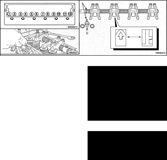
The valve clearance is measured between the top of the valve stem and the rocker arm as shown in Fig- ure 8.
Valve clearance (hot or cold)
Inlet |
0.20 mm (0.008 in.) |
Exhaust |
0.45 mm (0.018 in.) |
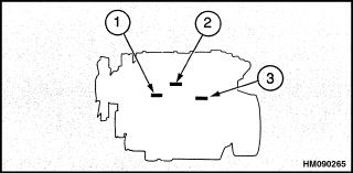
Number one cylinder is at the front of the engine. The inlet valve is the first valve in the sequence. See Figure 9.
1.Turn the crankshaft in the normal direction of rotation until the inlet valve of number six cylinder has just opened and the exhaust valve of the same cylinder has not fully closed. Check the clearances of the valves of number one cylinder and adjust them as necessary.
Figure 9. Valve Positions
NOTE: The torque for the locking nut is 27 N•m (21 lbf ft).
2.Turn the crankshaft in the normal direction of rotation until the inlet valve of number two cylinder has just opened and the exhaust valve of the same cylinder has not fully closed. Check the valve clearances on number five cylinder and adjust them as necessary.
7
Cylinder Head Assembly Repair |
600 SRM 1068 |
3.Turn the crankshaft in the normal direction of rotation until the inlet valve of number four cylinder has just opened and the exhaust valve of the same cylinder has not fully closed. Check the valve clearances on number three cylinder and adjust them as necessary.
4.Turn the crankshaft in the normal direction of rotation until the inlet valve of number one cylinder has just opened and the exhaust valve of the same cylinder has not fully closed. Check the valve clearances on number six cylinder and adjust them as necessary.
5.Turn the crankshaft in the normal direction of rotation until the inlet valve of number five cylinder has just opened and the exhaust valve of the same cylinder has not fully closed. Check the valve clearances on number two cylinder and adjust them as necessary.
6.Turn the crankshaft in the normal direction of rotation until the inlet valve of number three cylinder has just opened and the exhaust valve of the same cylinder has not fully closed. Check the valve clearances on number four cylinder and adjust them as necessary.
NOTE: After valve adjustments, lubricate the rocker assembly with clean engine oil.
VALVE SPRINGS
NOTE: This procedure is normally for changing the valve springs of a single cylinder while the cylinder head is still installed on the engine. If the valves and springs must be removed from the cylinder head for repairs, see the procedures under Valves and Valve Springs, later in this section.
Special Tools: Valve spring compressor Stud adapter
Setscrew adapter
1.Remove the valve cover.
2.Turn the crankshaft in the normal direction of rotation until the piston for the cylinder is at top dead center (TDC). The inlet valve will just open and the exhaust valve will not be fully closed when the cylinder is at TDC.
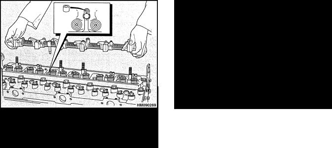
3.Remove the rocker arm assembly.
4.Install the spring compressor and the adapter. See Figure 10.
|
|
|
1. |
VALVE SPRING |
3. SETSCREW |
|
COMPRESSOR |
ADAPTER |
2. |
STUD ADAPTER |
|
Figure 10. Valve Spring Compressor
5.Compress the valve springs and remove the retainers. Verify the valve springs are compressed parallel to the valve stems, or the valve stems can be damaged.
NOTE: Do not turn the crankshaft while the valve springs are removed.
6.Release the valve spring compressor and remove the retainer cap and valve springs.
NOTE: The outer diameter of the exhaust valve guide is 1 mm (0.039 in.) larger than the inlet valve guide. To prevent leakage past the inlet valve stem it is important that the larger exhaust valve seal is not fitted into the inlet guide. The seals are color coded.
7.Install new valve stem seals on the valve guides. Verify that the brown seal is installed on the exhaust valve and the green seal on the inlet valves.
8.Install the new valve springs. The springs can be fitted with either end toward the cylinder head.
9.Install the retainer cap.
10.Use the valve spring compressor to compress the valve springs and install the retainers. Remove the valve spring compressor.
11.Install the rocker arm assembly.
12.Check the valve clearances. See Valve Clearance Adjustments.
13.Install the valve cover.
8
600 SRM 1068
NOTE: Valve springs can be changed in two cylinders at a time.
When the piston in cylinder one is at TDC, the piston in cylinder six is also at TDC. When the piston in cylinder two is at TDC, the piston in cylinder five is also at TDC. When the piston in cylinder three is at TDC, the piston in cylinder four is also at TDC.
If the rocker arm assembly was removed before TDC was found, install the valve spring compressor and compress the valve springs to open the valve. Turn the crankshaft by hand in the normal direction until the piston touches the valve. Continue to turn the crankshaft and, at the same time, release the pressure on the valve spring compressor until the piston is at TDC. See Figure 11.
Figure 11. Find TDC With Valve Spring
Compressor
Cylinder Head Assembly Repair
CYLINDER HEAD ASSEMBLY
Remove
1.If the engine is still in the lift truck, do the following procedures:
a.Disconnect the battery terminals.
b.Drain the cooling system.
c.Disconnect the sender unit for the coolant temperature gauge.
2.If equipped, remove closed circuit breather unit.
3.Remove the Machine Interface Connector (MIC) connection from the mounting bracket if the mounting bracket is attached to the cylinder head.
4.Remove the air intake hose.
5.Remove the fuel line between the cold start aid in the induction manifold and the fuel filter. Disconnect the electrical connection and electrical connectors from sensors.
6.Disconnect all connections to the turbocharger and remove turbocharger. See Turbocharger, Re- move.
7.Remove the induction manifold capscrews.
8.Remove the induction manifold and gasket from the cylinder head. Discard the gasket.
9.Remove exhaust manifold fasteners and the exhaust manifold.
10.Remove the low pressure fuel lines between the fuel injection pump and the fuel filter. Remove the fuel filter bracket and the fuel filters.
11.Remove the high pressure fuel lines. Use a separate wrench to prevent movement of the outlets of the fuel injection pump when the fuel lines are disconnected. Put plugs in the open ports of the fuel injection pump.
12.Remove the fuel injectors from the cylinder head. Keep the fuel injectors clean and prevent damage to the nozzles.
13.If an air compressor is installed, remove the coolant pipe between the cylinder head and the compressor. Remove the coolant pipe between the bypass connection and the compressor.
9
Cylinder Head Assembly Repair
14.Loosen the hose clamp and remove the coolant bypass hose from the cylinder head. Remove the capscrews and remove the coolant bypass connection and the hose.
15.Disconnect the coolant temperature sender.
16.Remove the valve cover. See Valve Cover, Re- move.
600 SRM 1068
17.Remove the rocker arm assembly. See Rocker Arm Assembly, Remove.
18.Remove the push rods.
19.Loosen the capscrews for the cylinder head evenly in a reverse sequence from the sequence shown in Figure 12.
Figure 12. Cylinder Head Tightening Sequence
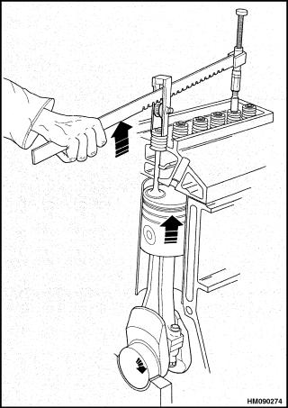
20.Lift the cylinder head from the engine block. Do not use a pry bar between the cylinder head and the engine block, that can cause damage to the gasket surfaces. See Figure 13.
Figure 13. Cylinder Head Removal
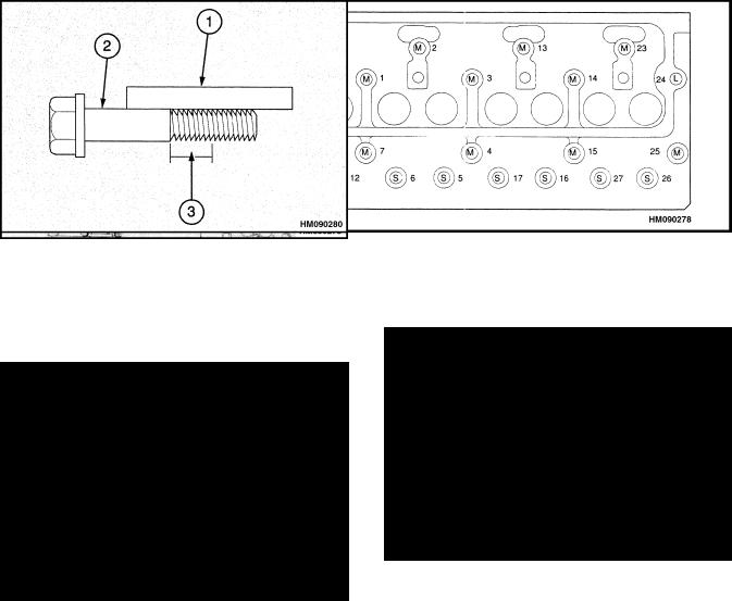
21.Inspect the capscrews for the cylinder head with a straightedge. See Figure 14. Check that the capscrews are straight and do not have distortion. If there is a reduction in the diameter of the
thread that has not been in engagement with the cylinder block, the capscrew must be discarded.
1.STRAIGHTEDGE
2.CAPSCREW MUST BE STRAIGHT AND WITHOUT DISTORTION
3.THREADS MUST BE IN GOOD CONDITION AND NOT HAVE A REDUCED DIAMETER
Figure 14. Capscrews Inspection
10
600 SRM 1068
Install
Special Tools: |
Angle gauge to tighten the |
|
capscrews for the cylinder head |
1.Verify the surfaces of the cylinder head and the top of the engine block are clean. Verify that there is no dirt or objects in the cylinders.
2.Install the gasket for the cylinder head as shown in Figure 15. Verify the TOP FRONT is in the correct position. Do not use any gasket sealant on any of the surfaces.
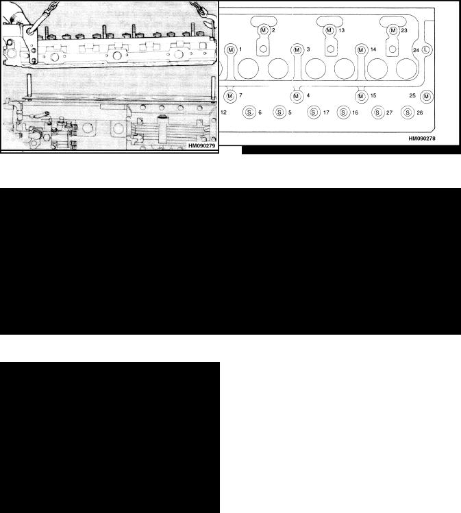
3.Use two 1/2 UNF studs in positions 25 and 30. See Figure 16. Lower the cylinder head into position on the engine block. See Figure 17.
Cylinder Head Assembly Repair
Figure 15. Head Gasket Position
Figure 16. Cylinder Head Tightening Sequence
 CAUTION
There are three lengths of capscrews. S = short, M = medium, L = long. Figure 16 shows their positions in the engine. Verify that the capscrews are installed in the correct positions.
4. |
Lubricate the capscrews with a thin coat of oil |
|
and install them into their holes in the cylinder |
|
head. When the cylinder head and gasket are |
|
held in position, remove the two studs and install |
|
the two capscrews in those positions. |
5. |
Evenly tighten the capscrews in the sequence |
Figure 17. Cylinder Head Installation |
shown in Figure 16. The final torque on the cap- |
screws is 110 N•m (81 lbf ft). |
11

Cylinder Head Assembly Repair
6.Verify all of the capscrews are tightened to the correct torque described in Step 5. The capscrews must be further tightened in the sequence shown in Figure 16 according to the following procedure:
a.The short capscrews (S) must be tightened an additional 150 (2.5 flats).
b.The medium capscrews (M) must be tightened an additional 180 (3.0 flats).
c.The long capscrews (L) must be tightened an additional 210 (3.5 flats).
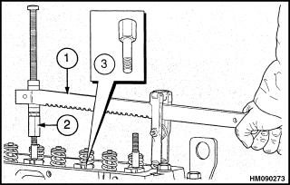
NOTE: A special tool shown in Figure 18 can be used for this procedure to measure the tightening angles. If an angle gauge is not available, make a mark in a line with one of the corners of the capscrew. See Figure 19. Make another mark at the correct angle (counterclockwise) on the edge of the flange of the cylinder head for each capscrew and according to the length of each capscrew. Tighten each capscrew in the correct sequence until the two marks are aligned.
7.Install the push rods in the engine. Verify that the end of each push rod fits correctly in the tappet socket.
Figure 18. Angle Gauge
Figure 19. Tighten Cylinder Head Capscrews
600 SRM 1068
8.Install the rocker arm assembly per Rocker Arm Assembly, Installl.
9.Adjust the valve clearances per Valve Clearance Adjustments.
10.Install the fuel injectors per Fuel Injectors, In- stall.
11.Install the high pressure fuel lines between the fuel injection pump and the fuel injectors. Use a separate wrench to prevent movement of the outlets of the fuel injection pump when the fuel lines are connected. Tighten the connection nuts to 27.5 N•m (20 lbf ft).
12.Install the fuel filter and bracket. Install the lowpressure fuel lines between the fuel filter and the fuel injection pump.
13.If equipped, reinstall the MIC to the MIC mounting bracket.
14.Install the coolant bypass connection. Tighten the capscrews and the hose clamp.
15.If an air compressor is installed on the engine, install the coolant pipe between the cylinder head and the compressor. Install the pipe between the coolant bypass and the compressor.
NOTE: Do not use sealant compound on gaskets of the manifold.
16.Verify the exhaust manifold gaskets and gasket surfaces are clean and not damaged.
17.Place the temporary studs in the cylinder head.
a.For two-piece exhaust manifolds, place temporary studs in positions 4, 8, 11, and 15 of the cylinder head. See Figure 20.
Figure 20. Two-Piece Exhaust Manifold
Tightening Sequence
12
600 SRM 1068 |
Cylinder Head Assembly Repair |
b.For three-piece exhaust manifolds, place temporary studs in positions 2, 5, 14, and 17 of the cylinder head. See Figure 21.
Figure 21. Three-Piece Exhaust Manifold
Tightening Sequence
18.Place the exhaust manifold gaskets in position over the studs. Verify the gaskets are in the correct position.
19.Reassemble the sections of the exhaust manifold and place in position over the temporary studs.
20.Insert the capscrews into all positions that do not have temporary studs and torque to 12.5 N•m (9 lbf ft).
21.Remove temporary studs and insert remaining capscrews and torque to 12.5 N•m (9 lbf ft).
22.Torque the capscrews again in sequence to 12.5 N•m (9 lbf ft). See Figure 20 and Figure 21.
 CAUTION
Before the inlet manifold capscrews are installed again, any loose M.E.A.S in the cylinder head holes must be removed to allow the manifold to be fully tightened.
Do not scratch or damage the flange faces of the inlet manifold.
NOTE: The capscrews that retain the manifold to the cylinder head have M.E.A.S applied to the threads. If the capscrews are removed and installed again, the threads must be cleaned and POWERPART threadlock sealant used.
23.Place a new induction manifold gasket into position on the cylinder head.
24.Place the induction manifold in position on the cylinder head.
25.Install the induction manifold capscrews and torque in sequence to 22 N•m (16 lbf ft). See Figure 22.
Figure 22. Induction Manifold Tightening
Sequence
26.Install the fuel line between the fuel filter and the cold start aid. If the engine is in the lift truck, install the electrical connection to the cold start aid.
27.Install the air intake hose.
28.Install the turbocharger. See Turbocharger, In- stall.
29.Install the closed circuit breather assembly if previously removed.
30.Install the fuel lines between the fuel filter and the fuel injection pump.
31.If the engine is still in the lift truck, do the following procedures:
a.Connect the sender unit for the coolant temperature gauge.
b.Connect the hoses for the coolant system. Fill the cooling system.
c.Connect the battery terminals.
d.If the engine is ready to operate, remove the air from the fuel system. See the procedure described in Fuel System Air Removal.
32.When the engine can be started, run it at low speed. Check that oil flows from the holes in the rocker arms. If the oil flow is correct, install the valve cover. See Valve Cover, Install.
NOTE: It is not necessary to tighten the cylinder head capscrews again with the engine hot or after a limited period of service.
13
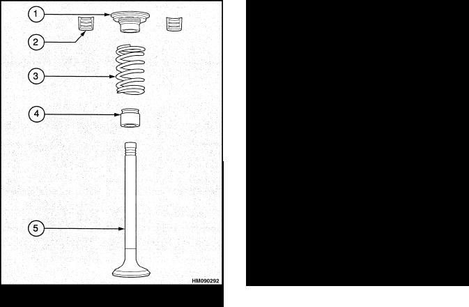
Cylinder Head Assembly Repair |
600 SRM 1068 |
VALVES AND VALVE SPRINGS
Special Tools: Valve spring compressor
Stud adapter
Setscrew adapter
Remove
1.Remove the cylinder head. See Cylinder Head Assembly, Remove.
2.Clean the bottom face of the cylinder head and check the depth of the heads of the valves below the face of the cylinder head. See Figure 23.
Figure 23. Valves Depth Check
3.Check the depth of the valves below the face of the cylinder head before the valve springs are removed. Put the dial indicator and fixture or other measuring tool on the face of the cylinder head and set the gauge to zero. Carefully put the dial indicator over the head of each valve and make a note of the measurement. The maximum service depth is shown in the Engine Specifications. If a valve is below the depth limit, remove the valve and install a new valve in that position. If the valve depth is still below the limit, the valve seat must be replaced. See New Valve Seats, Install.
4.If the valves will be used again, make a mark on each valve head so that they can be installed again in the same positions.
5.Use the valve spring compressor and the correct adapter to compress the valve springs and remove the retainers. Verify the valve springs are compressed parallel to the valve stems, or the valve stems can be damaged. See Figure 24.
1. |
CAP |
4. |
VALVE STEM SEAL |
2. |
COLLET (2) |
5. |
VALVE |
3. |
SPRING |
|
|
Figure 24. Valve Components
6.Release the valve stem compressor. Remove the valve spring cap, valve springs, and seal.
7.Repeat Step 5 and Step 6 to remove the other valves.
Inspect
1.Check the valves for cracks. Check the stems of the valves for wear and the correct clearance in their valve guides. See Valve Guides.
2.Check that the seat faces of the valves are not badly burned. Seat faces of valves that are damaged, but can be repaired, must be checked for valve depth when they are installed. See Fig- ure 23. When new valves are installed, the valve depth must be checked.
3.Check that the load on the valve springs is correct at their installed length. See Engine Speci- fications.
14
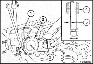
600 SRM 1068
4.Install new valve springs during a complete overhaul of the engine.
Install
1.Lubricate the valve stems with engine oil when they are installed in their valve guides.
 CAUTION
The outer diameter of the exhaust valve guide is 1 mm (0.039 in.) larger than the inlet valve guide. To prevent leakage past the inlet valve stem it is important that the larger valve seal is not installed into the inlet guide. The seals are color coded.
2.Install new seals on the valve guides. Verify that the brown seal is installed on the exhaust valves and the green seal is installed on the inlet valves.
3.Install the inner and outer valve springs on the seat washer. The springs can be installed with either end to the cylinder head.
4.Use the valve spring compressor and the correct adapter to compress the valve springs. Install the retainers. Verify the valve springs are compressed parallel to the valve stems or the valve stems can be damaged.
5.Repeat the installation procedure for each valve.
VALVE GUIDES
Inspect
1.Check the valve guides for wear. The maximum clearance between the valve stem and the bore of the guide is 0.100 mm (0.004 in.) for inlet valves and 0.121 mm (0.005 in.) for exhaust valves. If the clearance is greater than the limit when a new valve is installed, the valve guide must be replaced.
2.The following procedure is for checking the valve guides (see Figure 25):
a.Put a new valve into the valve guide.
b.Install a dial indicator on the cylinder head.
c.Lift the head of the valve approximately 15 mm (0.6 in.) above its seat. Move the
Cylinder Head Assembly Repair
valve head away from the plunger of the dial indicator and set the dial indicator to zero.
d.Move the valve toward the dial indicator and make a note of the movement. If the reading is equal to or greater than the maximum clearance, a new valve guide must be installed.
|
|
|
|
1. |
MAGNETIC BASE |
4. |
VALVE GUIDE |
2. |
DIAL INDICATOR |
5. |
MAXIMUM |
3. |
VALVE HEAD |
|
CLEARANCE |
Figure 25. Valve Guides Check
NOTE: The partially finished valve guides are reamed and the valve seats are cut in one operation with a special tool. This is done to ensure the concentricity of the valve seat to the valve guide and provide a good seal between the guide and its seat. New valves and valve seat inserts must be installed each time a new valve guide is used.
Remove
Install the tool for removal and replacement and the adapter on the valve guide. Pull the valve guide from the cylinder head. See Figure 26.
Install
1.Verify the bore in the cylinder head is clean.
2.Lubricate the outer surface of the new valve guide with engine oil.
15
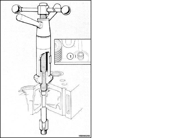
Cylinder Head Assembly Repair |
|
600 SRM 1068 |
|
|
|
|
|
|
|
|
|
Figure 26. Valve Guide Removal
3.Install the valve guide on the special tool. See Figure 27. Use the special tool to pull the valve guide into the cylinder head. When the valve guide is correctly installed, the valve guide will extend 14.85 to 15.15 mm (0.585 to 0.596 in.) above the seat of the valve spring.
CYLINDER HEAD AND VALVE SEATS
Inspect
The cylinder head must be removed and the valves must be removed from the cylinder head before the valve seats can be inspected and repaired. Carefully clean the cylinder head.
1.Check the cylinder head for cracks. Carefully check the areas around the valve seats and around the holes for the fuel injectors.
1.14.85 to 15.15 mm (0.585 to 0.596 in.) ABOVE SEAT OF VALVE SPRING
Figure 27. Valve Guide Installation
2.Use a straightedge and spacer gauges to check the cylinder head for distortion across and along its face that joins the engine block. See Engine Specifications. If the distortion is more than the specifications, the face can be machined. Remove only the minimum metal so that the thickness of the cylinder head will not be less than 102.79 mm (4.047 in.) after the cylinder head has been machined.
NOTE: After the cylinder head has been machined, the valve seats must be checked for the correct depth. See Valves and Valve Springs, Inspect. If the depth of the valve seats must be increased, use the minimum limit to allow for later wear.
3.Check the valve seats for wear and damage. Before any work is done on the valve seats, verify
16
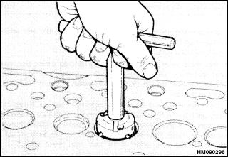
600 SRM 1068
the valve guides are good. See Valve Guides, In- spect for inspection and replacement.
4.Damaged valve seats can be repaired with a cutter tool. See Figure 28. If the valve seat cannot be repaired so that the valve depth is within the specifications, the valve seat must be replaced.
Figure 28. Valve Seats Cutter
Repair
Special Tools: |
Cutter for inlet valve seats |
|
Cutter for exhaust valve seats |
|
Valve guides reamer |
1.Install the correct cutter into the valve seat that is to be repaired. Carefully turn the cutter in a clockwise direction. Remove only the minimum metal to repair the valve seat. Keep the valve seat as narrow as possible.
2.When the valve seat has been cut, remove the cutter and pilot. Clean the port area and remove any particles.
Piston and Connecting Rod Assemblies Repair
3.Check the valve depth. See Valves and Valve Springs, Inspect. If the valve seat is badly damaged or worn, replace the valve seat as described in the following paragraphs.
New Valve Seats, Install
1.Remove the valve guide. Clean the bore and install a new valve guide. See Valve Guides for inspection and replacement.
2.Use the bore of the new valve guide as a pilot and use a milling machine to remove the old valve seat. See the Engine Specifications. Clean the particles from the port and the area where the new valve seat will be installed.
3.If the bottom face of the cylinder head has been machined, the back face of the new valve seat must be machined so that it will not extend above the surface of the cylinder head. If the back face of the valve seat is machined, verify that the dimensions of the outer edge of the back face are within the Engine Specifications.
4.Use the bore of the valve guide as a pilot. Use a press to install the valve seat into the cylinder head. Verify the valve seat is fully inserted into the cylinder head.
5.Use a cutter to cut the valve seat at the correct angle. Check the valve depth as shown in Fig- ure 23. Verify that the dimensions are within the Engine Specifications.
Piston and Connecting Rod Assemblies Repair
The connecting rods are forged from steel. The piston height is controlled by the length of the connecting rod. Each piston and connecting rod is matched to a cylinder during assembly to verify the piston height is correct for combustion efficiency to meet emission standards.
The manufacturer uses six length grades of connecting rods during assembly to give the correct piston height. These six length grades are made by machining the small-end bushing a small amount off-center.
Connecting rods for service replacement are available in two length grades.
The combustion chamber is machined into the top of the piston. See Figure 29. The pistons have two compression rings and an oil control ring. The groove for the top compression ring has a hard metal insert to reduce wear in the groove. The piston skirt has a layer of graphite to reduce wear.
17
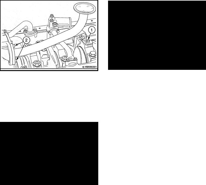
Piston and Connecting Rod Assemblies Repair
Figure 29. Piston
ROD BEARINGS
The engine has grooves (serrations) that are machined in the joint faces of the connecting rod and bearing cap to keep alignment between the two parts. The bearing cap is fastened to the connecting rod with two nuts and special bolts. See Figure 30.
1. SERRATIONS
Figure 30. Connecting Rod Assembly With
Serrations
Remove
1.Drain the engine oil from the sump. Remove the oil sump. See Oil Sump, Remove.
2.Remove the suction pipe and oil strainer. See Figure 31. Remove the capscrew that holds the bracket to the main bearing cap. Remove the two capscrews from the flange of the suction pipe and remove the suction pipe and screen. Clean the faces of both flanges.
600 SRM 1068
1.SUPPORT BRACKET, MAIN BEARING CAP
2.CAPSCREWS, FLANGE, SUCTION PIPE
Figure 31. Sump Screen Removal
3.Turn the crankshaft until the connecting rod to be removed is at the lowest position on the crankshaft.
 CAUTION
Do not permit the connecting rods to hit the cooling jets for the pistons. If a cooling jet is hit, the alignment must be checked and the cooling jet replaced if necessary.
4.Remove the nuts and remove the bearing cap.
5.Remove the lower bearing half from the bearing cap. Keep the bearing half with its cap.
6.Carefully push the connecting rod up the cylinder bore just enough to permit access to the upper bearing half. Remove the upper bearing half from the connecting rod. Keep the bearing halves together.
Install
1.Clean the bearing surfaces of the connecting rod and the crankshaft. Clean the bearing halves and lubricate them with clean engine oil.
2.Install the upper bearing half into the connecting rod. Verify that the location tab is installed correctly into its position in the connecting rod. See Figure 32.
18
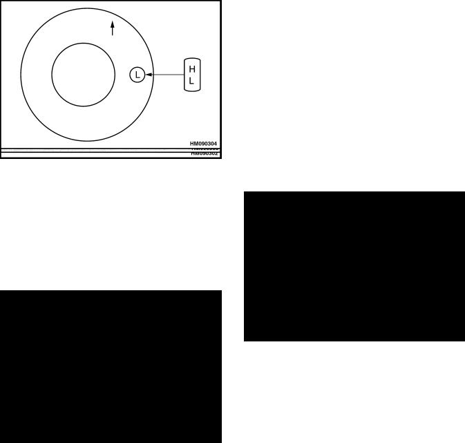
600 SRM 1068
1.POSITION OF LOCATION TAB IN BEARING HALF AND CONNECTING ROD
Figure 32. Rod Bearings Position
3.Install the bearing cap on the connecting rod. Verify that the assembly number on the bearing cap is the same as the assembly number on the connecting rod. Verify that the two assembly numbers are on the same side of the connecting rod as shown in Figure 33.
Piston and Connecting Rod Assemblies Repair
pump. Verify that the suction pipe is aligned correctly and then tighten the capscrew that holds the bracket to the main bearing cap.
6. Install the oil sump. See Oil Sump, Install.
PISTON AND CONNECTING ROD ASSEMBLY
Service Note
If a piston must be replaced, verify that the piston has the same length grade. An H or an L is stamped into the top of the piston. See Figure 34. A production piston does not have an H or an L mark. The piston height must be checked after installation. See the procedure described in Install.
Figure 33. Bearing Cap Position, Connecting
Rod
NOTE: New nuts must be installed with the bolts that secure the cap.
4.Install and tighten the nuts evenly to a torque of 125 N•m (92 lbf ft). Verify that the crankshaft turns freely.
5.Loosely assemble the bracket of the suction pipe to the main bearing cap. Install a new gasket and fasten the flanges of the suction line to the oil
Figure 34. Piston Grade Mark
Remove
1.If the engine is still in the lift truck, drain the engine oil and the coolant.
2.Remove the cylinder head assembly as described in Cylinder Head Assembly, Remove. Remove the carbon from the tops of the bores of the cylinder liners.
3.Remove the oil sump. See Oil Sump, Remove.
4.Remove the suction line and oil strainer. See Figure 31. Remove the capscrew that holds the bracket to the main bearing cap. Remove the two capscrews from the flange of the suction line and remove the suction line and screen. Clean the faces of both flanges.
5.Remove the bearing cap and rod bearings as described under Rod Bearings, Remove. Mark the
19
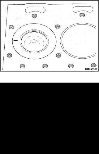
Piston and Connecting Rod Assemblies Repair |
600 SRM 1068 |
bearing caps and rod bearings so that they can be installed again in their original positions.
 CAUTION
Do not permit the connecting rods to hit the cooling jets for the pistons. If a cooling jet is hit, the alignment must be checked and the cooling jet replaced if necessary.
6.Push the piston and connecting rod out of the top of the cylinder liner.
7.Inspect the bearing surfaces on the crankshaft for damage.
Install
Special Tools: |
Piston installation tool (piston ring |
|
compressor) |
|
Piston height tool |
|
Dial indicator gauge |
1.Verify all of the parts are clean. Lubricate the parts with engine oil as they are installed.
2.Turn the crankshaft until the position for the connecting rod to be installed is at the lowest position on the crankshaft.
3.Install the upper bearing half into the connecting rod. Verify that the location tab is installed correctly into its position in the connecting rod. See Figure 32.
4.Put the piston installation tool at the top of the cylinder. See Figure 35. The tool has a bore with a taper to compress the piston rings when the piston and connecting rod assembly is installed. Verify the smaller end of the taper is toward the cylinder block.
5.Put the open gaps in the three piston rings so that the gaps are 120 apart. Put the connecting rod through the piston installation tool and permit the piston to enter the tool. The piston and connecting rod must be turned so that the connecting rod does not hit the cooling jet for the piston.
6.When the connecting rod has passed the cooling jet during installation, the arrow or FRONT mark on the piston must be turned toward the front of the engine. See Figure 36.
Figure 35. Piston Installation Tool
Figure 36. Piston in Bore Position
7.Lubricate the lower half of the rod bearing and install it into the bearing cap.
8.Install the bearing cap on the connecting rod. Verify that the assembly number on the bearing cap is the same as the number on the connecting rod. Verify that the two assembly numbers are on the same side of the connecting rod as shown in Figure 33.
NOTE: New nuts must be installed with the bolts that secure the cap.
9.Install and tighten the nuts evenly to a torque of 125 N•m (92 lbf ft). Verify that the crankshaft turns freely.
10.Measure the height of the piston above the top of the engine block with a dial indicator gauge. The crankshaft must be turned so that the piston is at TDC in the engine block. Put the dial indicator on the top of the engine block and measure the
20
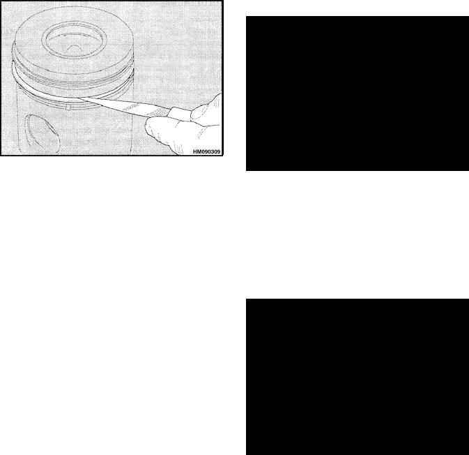
600 SRM 1068 |
Piston and Connecting Rod Assemblies Repair |
height of the piston above the face of the engine block. See Figure 37.
The correct height of the piston above the engine block is 0.36 to 0.50 mm (0.014 to 0.020 in.). The tops of the pistons must not be changed or machined.
2.Clean the carbon from the top of the cylinder liners. Fit the piston rings in the top part of the cylinder liner and measure the clearance at the ends of the ring. See Figure 38. The spring must be installed in the oil control ring when its end clearance is measured. The clearance measurements for the piston rings are shown in the En- gine Specifications.
Figure 37. Piston Height Above Engine Block
Measurement
11.Loosely assemble the bracket of the suction pipe to the main bearing cap. Install a new gasket and fasten the flanges of the suction pipe to the oil pump. Verify that the suction pipe is aligned correctly and tighten the capscrew that holds the bracket to the main bearing cap.
12.Install the oil sump. See Oil Sump, Install.
13.Install the cylinder head. See Cylinder Head Assembly, Install.
PISTON RINGS
Remove
1.Check that the piston rings can move freely in their grooves and are not broken.
2.Remove the piston rings with a ring expander. Increase the diameter of the piston rings only enough to remove them without damaging the piston.
Inspect
1. Check the piston for wear and damage.
Figure 38. Piston Ring End Clearance Check
3.Install new piston rings on the piston and check the clearance in the grooves with a spacer gauge. See Figure 39. If the clearance between the piston rings and the piston are greater than the specifications, the piston must be replaced. See the Engine Specifications. The clearance in the top groove of the pistons for these engines cannot be checked because it has a taper.
Figure 39. Piston Ring Clearance Check
21
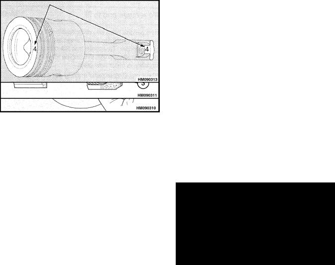
Piston and Connecting Rod Assemblies Repair
Install
Install the piston rings with a ring expander. Increase the diameter of the piston rings only enough to install them without damaging the piston.
1.Install the spring for the oil control ring in the bottom groove of the piston. See Figure 40. Install the latch pin inside both ends of the spring. See Figure 41. Install the oil control ring over the spring so that the end space in the oil control ring is 180 to the latch pin.
Figure 40. Spring Installation for Oil Control Ring
|
|
|
1. |
TOP RING |
3. OIL CONTROL |
2. |
SECOND RING |
RING AND SPRING |
Figure 41. Piston Rings Installation
 CAUTION
Verify that the word TOP or the manufacturer’s symbol is toward the top of the piston. New piston rings have a red identification mark which must be on the left of the clearance space at the ends of the ring when the
600 SRM 1068
ring is installed on the piston and the piston is upright.
2.Install the cast iron ring with the taper into the second groove of the piston. Verify that the word TOP or the manufacturer’s symbol is toward the top of the piston. New piston rings have a green identification mark which must be on the left of the clearance at the ends of the ring when the ring is installed on the piston and the piston is upright.
3.Install the tapered (top ring) with the TOP toward the top of the piston.
4.Check that the open gaps of the piston rings are spaced 120 apart before installing the piston.
PISTON AND CONNECTING ROD
Disassemble
1.Remove the piston rings as described in Piston Rings, Remove.
2.Make a mark on the piston to indicate the cylinder number as shown on the connecting rod. Make the mark on the same side of the piston as the number on the connecting rod. See Fig- ure 42.
3.Remove the snap rings that hold the piston pin in the piston. Push the piston pin from the piston with your thumb. If the piston pin is tight, heat the piston and connecting rod to 40 to 50 C (104 to 122
 F) to make removal of the piston pin easier.
Figure 42. Marking Piston
Inspect
1.Clean and inspect all the components for wear and damage. Check the alignment of the connecting rod with a test mandrel. See Figure 43.
22
Loading...