


1104E

SEBU8121
February 2005
Operation and
Maintenance
Manual
1104E Engine
RF11-Up
(Machine)
RH11-Up (Machine)
RK11-Up (Machine)

i01658146
Important Safety Information
Most accidents t
hat involve product operation, maintenance and repair are caused by failure to observe
basic safety rules or precautions. An accident can often be avoided by recognizing potentially hazardous
situations before an accident occurs. A person must be alert to potential hazards. This person should also
have the necess
ary training, skills and tools to perform these functions properly.
Improper operation, lubrication, maintenance or repair of this product can be dangerous and
could result in injury or death.
Do not operate o
r perform any lubrication, maintenance or repair on this product, until you have
read and understood the operation, lubrication, maintenance and repair information.
Safety precautions and warnings are provided in this manual and on the product. If these hazard warnings
are not heeded
, bodily injury or death could occur to you or to other persons.
The hazards are identified by the “Safety Alert Symbol” and followed by a “Signal Word” such as
“DANGER”, “WARNING” or “CAUTION”. The Safety Alert “WARNING” label is s hown below.
The meaning of this safety alert symbol is as follows:
Attention! Be
come Alert! Your Safety is Involved.
The message that appears under the warning explains the hazard and can be either written or pictorially
presented.
Operations th
at may cause product damage are identified by “NOTICE” labels on the product and in
this publication.
Perkins cannot anticipa te e ver y p os sible c irc u mstance t hat m ight invol ve a pote n ti al hazard .
The warnings
in this publication and on the product are, therefore, not all inclusive. If a tool,
proc edure, work me thod or ope rating technique tha t is not s pecific ally rec ommended by Perkins
is used, you must satisfy yourself that it is safe for you and for others. You should also ensure that
the product w
ill not be damaged or be made unsafe by the operation, lubrication, maintenance or
repair procedures that you choose.
The information, specifications, and illustrations in this publication are on the basis of information that
was availabl
e at the time that the publication was written. The specifications, torques, pressures,
measurements, adjustments, illustrations, and other items can change at any time. These changes can
affect the service that is given to the product. Obtain the complete and most current information before you
s t ar t any jo
b . Perkins dea le rs hav e t he m os t c ur r en t i nfo rm ati on a va il abl e.
When replacement parts are required for this
product Perkins re comme nds usi ng Perkins
re pl ac
e ment parts or parts w ith equiva lent
specifications including, but not limited to, phys-
ical dimensions, type , strength and material.
Failure to heed this warning can lead to prema-
ture failures, product damage, personal injury or
death.

SEBU8121 3
Table of Contents
Table of Contents
Foreword ................................................................. 4
Safety Section
Safety Messages .................................................... 5
General Hazard Information ................................... 5
Burn Prevention ...................................................... 7
Fire Prevention and Explosion Prevention .............. 7
Crushing Prevention and Cutting Prevention .......... 9
Before Starting Engine ............................................ 9
Engine Starting ....................................................... 9
Engine Stopping ................................................... 10
Electrical System .................................................. 10
Engine Electronics ................................................. 11
Product Information Section
General Information .............................................. 12
Model Views ......................................................... 13
Product Identification Information ........................ 17
Operation Section
Lifting and Storage ................................................ 19
Gauges and Indicators .......................................... 22
Features and Controls .......................................... 23
Engine Diagnostics ............................................... 27
Engine Starting ..................................................... 29
Engine Operation .................................................. 33
Engine Stopping ................................................... 34
Cold Weather Operation ....................................... 35
Maintenance Section
Refill Capacities .................................................... 39
Maintenance Interval Schedule ............................ 52
Warranty S ecti
on
Warranty Information ............................................ 81
Index Section
Index ..................................................................... 82

4 SEBU8121
Foreword
Foreword
Literature Information
This manual con
tains safety, operation instructions,
lubrication a nd maintenance information. This
manual should be stored in or near the engine area
in a literatur
e holder or literature storage area. Read,
study and keep it with the literature and engine
information.
English is the primary language for all Perkins
publications. The English used facilitates translation
and consiste
ncy.
Some photographs or illustrations in this manual
show details
or attachments that may be different
from your engine. Guards and covers may have
been removed for illustrative purposes. Continuing
improvemen
t and advancement of product design
may have caused changes to your engine which are
not included in this manual. Whenever a question
arises reg
arding your engine, or this manual, please
consult with your Perkins dealer or your Perkins
distributor for the latest available information.
Safety
This safety section lists basic safety precautions.
In addition, this section identifies hazardous,
warning si
tuations. Read and understand the basic
precautions listed in the safety section before
operating or performing lubrication, maintenance and
repair on
this product.
Operatio
n
Operating techniques outlined in this manual are
basic. Th
ey assist with developing the skills and
techniques required to operate the engine more
efficiently and economically. Skill and techniques
develop
as the operator gains knowledge of the
engine and its capabilities.
The oper
ation section is a reference for operators.
Photographs and illustrations guide the operator
through procedures of inspecting, starting, operating
and sto
pping the engine. This section also includes a
discussion of electronic diagnostic information.
Maintenance
The mai
ntenance section is a guide to engine care.
The illustrated, step-by-step instructions are grouped
by service hours and/or calendar time maintenance
interv
als. Items in the maintenance schedule are
referenced to detailed instructions that follow.
Recommended se
rvice should be performed at the
appropriate intervals as indicated in the Maintenance
Interval Schedule. The actual operating environment
of the engine a
lso governs the Maintenance Interval
Schedule. Therefore, under extremely severe,
dusty, wet or freezing cold operating conditions,
more frequen
t lubrication and maintenance than is
specified in the Maintenance Interval Schedule may
be necessary.
The maintenance schedule items are organized for
a preventive maintenance management program. If
the prevent
ive maintenance program is followed, a
periodic tune-up is not required. The implementation
of a preventive maintenance management program
should mini
mize operating costs through cost
avoidances resulting from reductions in unscheduled
downtime and failures.
Maintenance Intervals
Perform maintenance on items at multiples of
the original requirement. We recommend that the
maintenan
ce schedules be reproduced and displayed
near the engine as a convenient reminder. We also
recommend that a maintenance record be maintained
as part of
the engine’s permanent record.
Your authorized Perkins dealer or your Perkins
distribu
tor can assist you in adjusting your
maintenance schedule to meet the needs of your
operating environment.
Overhaul
Major engine overhaul details are not covered in
the Operation and Maintenance Manual except
for the i
nterval and the maintenance items in that
interval. Major repairs should only be carried out by
Perkins authorized personnel. Your Perkins dealer
or your P
erkins distributor offers a variety of options
regarding overhaul programs. If you experience
a major engine failure, there are also numerous
after f
ailure overhaul options available. Consult with
your Perkins dealer or your Perkins distributor for
information regarding these options.
California Proposition 65 Warning
Diesel engine exhaust and some of its constituents
are known to the State of California to cause cancer,
birth
defects, and other reproductive harm. Battery
posts, terminals and related accessories contain lead
and lead compounds. Wash hands after handling.
SEBU8121 5
Safety Section
Safety Messages
Safety Section
i02206606
Safety Me ssage s
There may be s
everal specific warning signs on
an engine. The exact location of the hazards and
the description of the hazards are reviewed in this
section. Ple
ase become familiar with all warning
signs.
Ensure that a
ll of the warning signs are legible. Clean
the warning signs or replace the warning signs if
the words cannot be read or if the pictures are not
visible. Wh
en the warning signs are cleaned, use a
cloth, water, and soap. Do not use solvent, gasoline,
or other harsh chemicals to clean the warning signs.
Solvents,
gasoline, or harsh chemicals could loosen
the adhesive that secures the warning signs. The
warning signs that are loosened could drop off of
the engine
.
Replace any damaged warning signs or missing
warning si
gns. If a warning sign is attached to a part
of the engine that is replaced, install a new warning
sign on the replacement part. Perkins dealers or
Perkins d
istributors can provide new warning signs.
Do not work on the engine and do not operate the
engine un
less the instructions and warnings in the
Operation and Maintenance Manual are understood.
Correct care is your responsibility. Failure to follow
the inst
ructions or failure to heed the warnings could
result in injury or in death.
The warn
ing labels that may be found on the engine
are illustrated and described.
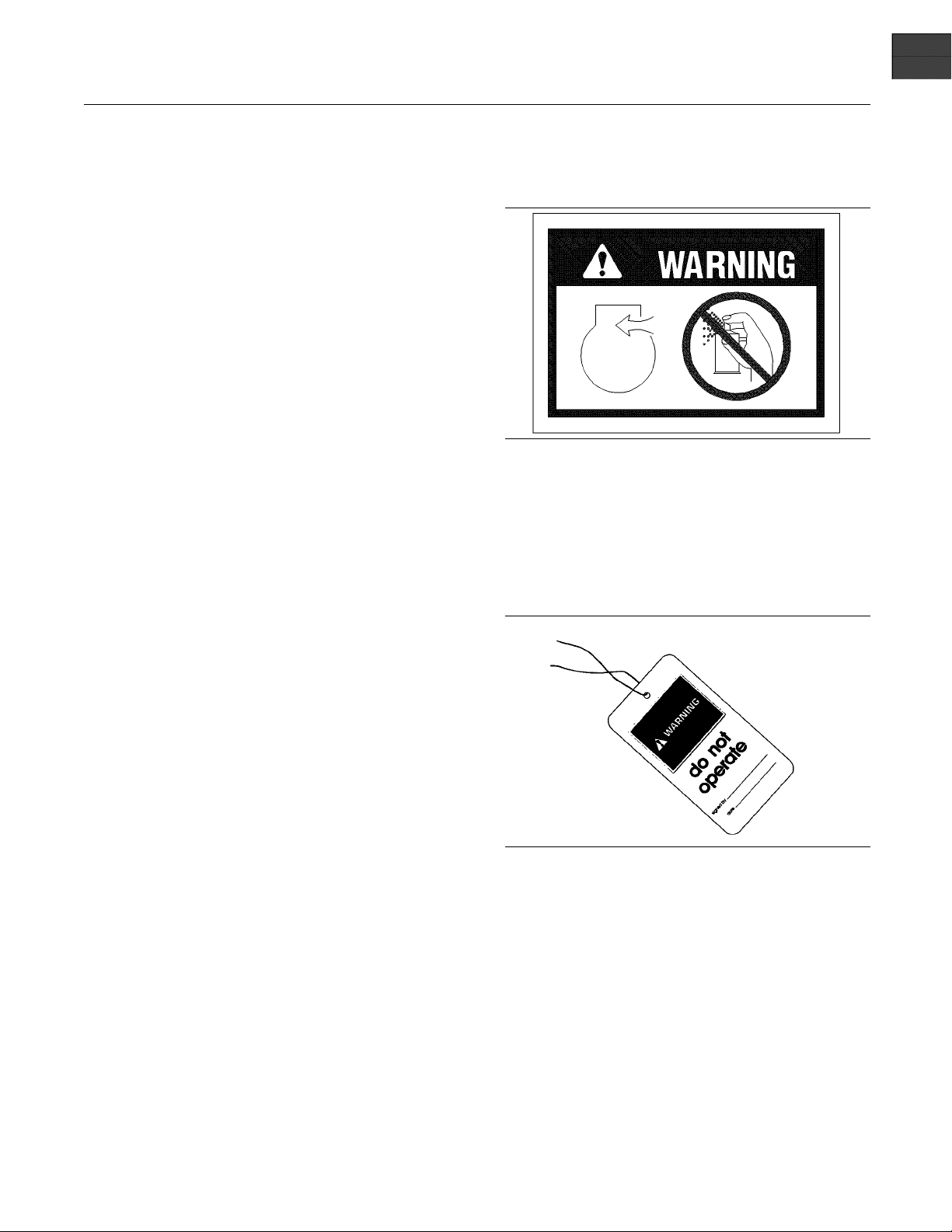
Ether
The warning lab
el for ether is located on the top, the
front, the rear, or the side of the engine.
g00640926
Never spray Ether starting aids into the air inl et.
i02203039
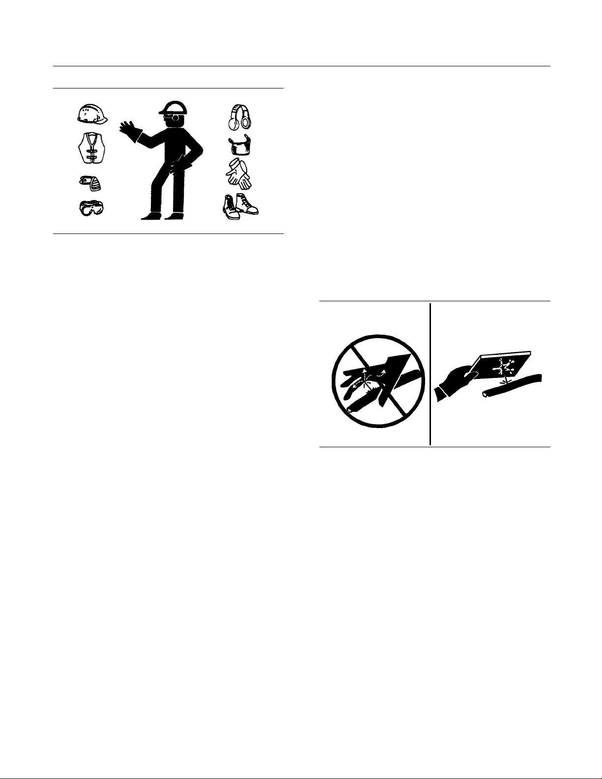
General Hazard Information
g00104545
Illustration 1
Attach a “
Do Not Operate” warning tag or a similar
warning tag to the start switch or to the controls
before you service the equipment or before you
repair th
eequipment.
6 SEBU8121
Safety Section
General Hazard Information
g00702020
Illustration 2
Wear a hard hat, protective glasses, and other
protective equipment, as required.
Do not wear loose clothing or jewelry that can snag
on controls or on other parts of the engine.
Make sure that all protective guards and all covers
are secured in place on the engine.
Keep the engine free from foreign material. Remove
debris, oil, tools, and other items from the deck, from
walkways, and from steps.
Never put maintenance fluids into glass containers.
Drain all liquids into a suitable container.
Obey all local regulations for the disposal of liquids.
Use all cleaning solutions with care. Report all
necessary repairs.
Do not allow unauthorized personnel on the
equipment.
Note: Ensure that the power supply is disconnected
before you work on the bus bar or the glow plugs.
Unless you are instructed otherwise, perform
maintenance on the engine with the equipment in
the servicing position. Refer to the OEM information
for the procedure for placing the equipment in the
servicing position.
Pressure Air and Water
Pressurized air and/or water can cause debris
and/or hot water to be blown out. This could result in
personal injury.
When pressurized air and/or water is used for
cleaning, wear protective clothing, protective shoes,
and eye protection. Eye protection includes goggles
oraprotectivefaceshield.
The maximum air
pressure for cleaning purposes
must be below 205 kPa (30 psi). The maximum
water pressure for cleaning purposes must be below
275 kPa (40 psi
).
Fluid Penetra
tion
Pressure can be trapped in the hydraulic circuit long
after the eng
ine has been stopped. The pressure can
cause hydraulic fluid or items such as pipe plugs to
escape rapidly if the pressure is not relieved correctly .
Do not remove any hydraulic components or parts
until pressure has been relieved or personal injury
may occur. Do
not disassemble any hydraulic
components or parts until pressure has been relieved
or personal injury may occur. Refer to the OEM
informatio
n for any procedures that are required to
relieve the hydraulic pressure.
g00687600
Illustration 3
Always use a board or cardboard when you check
for a leak. Leaking fluid that is under pressure can
penetrate body tissue. Fluid penetration can cause
serious injury and possible death. A pin hole leak can
cause severe injury. If fluid is injected into your skin,
you must get treatment immediately. Seek treatment
from a doctor that is familiar with this type of injury.
Containing Fluid Spillage
Care must be taken in order to ensure that fluids
are contained during performance of inspection,
maintenance, testing, adjusting and repair of the
engine. Make provision to collect the fluid with a
suitable container before any compartment is opened
or before any component is disassembled.
•
Only use the tools that are suitable for collecting
fluids and equipment that is suitable for collecting
fluids.
•
Only use the tools that are suitable for containing
fluids and equipment that is suitable for containing
fluids.
SEBU8121 7
Safety Section
Burn Prevention
Obey all local r
egulations for the disposal of liquids.
i02143195
Burn Prevention
Do not touch any part of an operating engine.
Allow the engine to cool before any maintenance
is performed on the engine. Relieve all pressure
in the air system, in the hydraulic system, in the
lubrication system, in the fuel system, or in the
cooling system before any lines, fittings or related
items are disconnected.
Coolant
When the engine is at operating temperature, the
engine coolant is hot. The coolant is also under
pressure. The radiator and all lines to the heaters or
to the engine contain hot coolant.
Any contact with hot coolant or with steam can cause
severe burns. Allow cooling system components to
cool before the cooling system is drained.
Check the coolant level after the engine has stopped
and the engine has been allowed to cool.
Ensure that the filler cap is cool before removing the
filler cap. The filler cap must be cool enough to touch
withabarehand.Removethefillercapslowlyin
order to relieve pressure.
Cooling system conditioner contains alkali. Alkali can
cause personal injury. Do not allow alkali to contact
the skin, the eyes, or the mouth.
Oils
Hot oil and hot lubricating components can cause
personal injury. Do not allow hot oil to contact the
skin. Also, do not allow hot components to contact
the skin.
Batteries
Electrolyte is an acid. Electrolyte can cause personal
injury. Do not allow electrolyte to contact the skin or
the eyes. Always wear protective glasses for servicing
batteries. Wash hands after touching the batteries
and connectors. Use of gloves is recommended.
i02203164
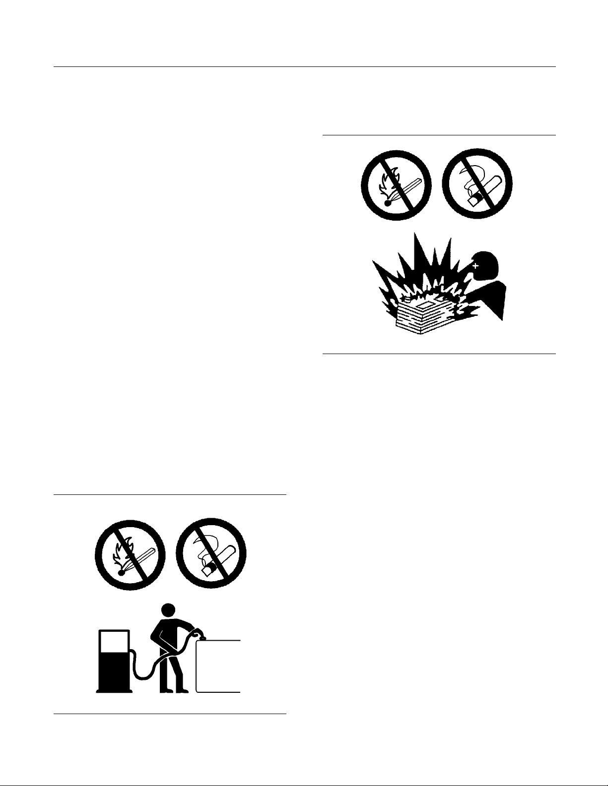
Fire Prevention and Explosion
Prevention
g00704000
Illustrati
on 4
All fuels, most lubricants, and some coolant mixtures
are flammab
le.
Flammable fluids that are leaking or spilled onto hot
surfaces or
onto electrical components can cause
a fire. Fire may cause personal injury and property
damage.
A flash fire may result if the covers for the engine
crankcase are removed within fifteen minutes after
an emergen
cy shutdown.
Determinewhethertheenginewillbeoperatedinan
environme
nt that allows combustible gases to be
drawn into the air inlet system. These gases could
cause the engine to overspeed. Personal injury,
property
damage, or engine damage could result.
If the application involves the presence of combustible
gases, co
nsult your Perkins dealer and/or your
Perkins distributor for additional information about
suitable protection devices.
Remove all flammable combustible materials or
conductive materials such as fuel, oil, and debris from
the engi
ne. Do not allow any flammable combustible
materials or conductive materials to accumulate on
the engine.
Store fuels and lubricants in correctly marked
containers away from unauthorized persons. Store
oily rag
s and any flammable materials in protective
containers. Do not smoke in areas that are used for
storing flammable materials.
Do not expose the engine to any flame.
8 SEBU8121
Safety Section
Fire Prevention and Explosion Prevention
Exhaust shield
s (if equipped) protect hot exhaust
components from oil or fuel spray in case of a line,
a tube, or a seal failure. Exhaust shields must be
installed cor
rectly.
Do not weld on lines or tanks that contain flammable
fluids. Do no
t flame cut lines or tanks that contain
flammable fluid. Clean any such lines or tanks
thoroughly with a nonflammable solvent prior to
welding or fl
ame cutting.
Wiring must be kept in good condition. All electrical
wires must be
correctly routed and securely attached.
Check all electrical wires daily. Repair any wires
that are loose or frayed before you operate the
engine. Cle
an all electrical connections and tighten
all electrical connections.
Eliminate a
ll wiring that is unattached or unnecessary.
Do not use any wires or cables that are smaller than
the recommended gauge. Do not bypass any fuses
and/or cir
cuit breakers.
Arcing or sparking could cause a fire. Secure
connectio
ns, recommended wiring, and correctly
maintained battery cables will help to prevent arcing
or sparking.
Inspect all lines and hoses for wear or for
deterioration. The hoses must be correctly routed.
The lines
and hoses must have adequate support
and secure clamps. Tighten all connections to the
recommended torque. Leaks can cause fires.
Oil filters and fuel filters must be correctly installed.
The filter housings must be tightened to the correct
torque.
g00704059
Illustration 5
Use caution whe
n you are refueling an engine. Do
not smoke while you are refueling an engine. Do not
refuel an engine near open flames or sparks. Always
stop the engin
e before refueling.
g00704135
Illustration 6
Gases from a battery can explode. Keep any open
flames or sparks away from the top of a battery. Do
not smoke in battery charging areas.
Never check the battery charge by placing a metal
object across the terminal posts. Use a voltmeter or
ahydrometer.
Incorrect jumper cable connections can cause
an explosion that can result in injury. Refer to
the Operation Section of this manual for specific
instructions.
Do not charge a frozen battery. This may cause an
explosion.
The batteries must be kept clean. The covers
(if equipped) must be kept on the cells. Use the
recommended cables, connections, and battery box
covers when the engine is operated.
Fire Extinguisher
Make sure that a fire extinguisher is available. Be
familiar with the operation of the fire extinguisher.
Inspect the fire extinguisher and service the fire
extinguisher regularly. Obey the recommendations
on the instruction plate.

SEBU8121 9
Safety Section
Crushing Prevention and Cutting Prevention
Lines, Tubes and Hoses
Do not bend high
pressure lines. Do not strike high
pressure lines. Do not install any lines that are bent
or damaged.
Repair any lines that are loose or damaged. Leaks
can cause fires. Consult your Perkins dealer or your
Perkins dist
ributor for repair or for replacement parts.
Check lines, tubes and hoses carefully. Do not use
your bare han
dtocheckforleaks.Useaboardor
cardboard to check for leaks. Tighten all connections
to the recommended torque.
Replace the parts if any of the following conditions
are present:
•
End fittings are damaged or leaking.
•
Outer cover
ings are chafed or cut.
•
Wires are exposed.
•
Outer coverings are ballooning.
•
Flexible pa
rt of the hoses are kinked.
•
Outer covers have embedded armoring.
•
End fittings are displaced.
Make sure tha
t all clamps, guards, and heat shields
are installed correctly. During engine operation, this
will help to prevent vibration, rubbing against other
parts, and e
xcessive heat.
i02143194
Crushing Prevention and
Cutting Pr
evention
Support the component correctly when work beneath
the component is performed.
Unless other maintenance instructions are provided,
never attempt adjustments while the engine is
running.
Stay clear of all rotating parts and of all moving
parts. Le
ave the guards in place until maintenance
is performed. After the maintenance is performed,
reinstall the guards.
Keep objects away from moving fan blades. The fan
blades will throw objects or cut objects.
When objects are struck, wear protective glasses in
order to avoid injury to the eyes.
Chips or other d
ebris may fly off objects when objects
are struck. Before objects are struck, ensure that no
one will be injured by flying debris.
i02157341
Before Starting Engine
NOTICE
For initial start-up of a new or rebuilt engine, and for
start-up of an engine that has been serviced, make
provision to shut the engine off should an overspeed
occur. This may be accomplished by shutting off the
air and/or fuel supply to the engine.
Overspeed shutdown should occur automatically.
If automatic shutdown does not occur, press the
emergency stop button in order to cut the fuel and/or
air to the engine.
Inspect the engine for potential hazards.
Before starting the engine, ensure that no one is on,
underneath, or close to the engine. Ensure that the
area is free of personnel.
If equipped, ensure that the lighting system for the
engine is suitable for the conditions. Ensure that all
lights work correctly, if equipped.
All protective guards and all protective covers must
be installed if the engine must be started in order
to perform service procedures. To help prevent an
accident that is caused by parts in rotation, work
around the parts carefully.
Do not bypass the automatic shutoff circuits. Do not
disable the automatic shutoff circuits. The circuits are
provided in order to help prevent personal injury. The
circuits are also provided in order to help prevent
engine damage.
See the Service Manual for repairs and for
adjustments.
i022072
32
Engine Starting
Do not use aerosol types of starting aids s uch as
ether. Such use could result in an explosion and
persona
linjury.

10 SEBU8121
Safety Section
Engine Stopping
If a warning tag
is attached to the engine start switch
or to the controls, DO NOT start the engine or move
the controls. Consult with the person that attached
the warning ta
g before the engine is started.
All protective guards and all protective covers must
be installed
if the engine must be started in order
to perform service procedures. To help prevent an
accident that is caused by parts in rotation, work
around the pa
rts carefully.
Start the engine from the operator’s compartment or
from the engi
ne start switch.
Always start the engine according to the procedure
that is descr
ibed in the Operation and Maintenance
Manual, “Engine Starting” topic in the Operation
Section. Knowing the correct procedure will help to
prevent maj
or damage to the engine components.
Knowing the procedure will also help to prevent
personal injury.
To ensure that the jacket water heater (if equipped)
and/or the lube oil heater (if equipped) is working
correctly
, check the water temperature gauge and the
oil temperature gauge during the heater operation.
Engine exh
aust contains products of combustion
which can be harmful to your health. Always start the
engine and operate the engine in a well ventilated
area. If t
he engine is started in an enclosed area,
vent the engine exhaust to the outside.
Note: The
engine is equipped with an automatic
device for cold starting for normal conditions of
operation. If the engine will be operated in very cold
conditi
ons, then an extra cold starting aid may be
required. Normally, the engine will be equipped with
the correct type of starting aid for your region of
operati
on.
The engines are equipped with a glow plug starting
aidinea
ch individual cylinder that heats the intake
air in order to improve starting.
i01928905
Engine Stopping
Stop the engine according to the procedure in
the Operation and Maintenance Manual, “Engine
Stopping (Operation Section)” in order to avoid
overheating of the engine and accelerated wear of
the engine components.
Use the Emergen
cy Stop Button (if equipped) ONLY
in an emergency situation. Do not use the Emergency
Stop Button for normal engine stopping. After an
emergency sto
p, DO NOT start the engine until the
problem that caused the emergency stop has been
corrected.
Stop the engine if an overspeed condition occurs
during the initial start-up of a new engine or an engine
that has been
overhauled. This may be accomplished
by shutting off the fuel supply to the engine and/or
shutting off the air supply to the engine.
i02176668
Electrical S ys tem
Never disconnect any charging unit circuit or battery
circuit cable from the battery when the charging unit
is operating. A spark can cause the combustible
gases that are produced by some batteries to ignite.
To help prevent sparks from igniting combustible
gases that are produced by some batteries, the
negative “−” jump start cable should be connected
last from the external power source to the negative
“−” terminal of the starting motor. If the starting motor
is not equipped with a negative “−” terminal, connect
the jump start cable to the engine block.
Check the electrical wires daily for wires that are
loose or frayed. Tighten all loose electrical wires
before the engine is started. Repair all frayed
electrical wires before the engine is started. See
the Operation and Maintenance Manual for specific
starting instructions.
Grounding Practices
Correct grounding for the engine electrical system
is necessary for optimum engine performance
and reliability. Incorrect grounding will result in
uncontrolled electrical circuit paths and in unreliable
electrical circuit paths.
Uncontrolled electrical circuit paths can result in
damage to main bearings, to crankshaft bearing
journal surfaces, and to aluminum components.
Engines that are installed without engine-to-frame
ground straps can be damaged by electrical
discharge.
To ensure that the engine and the engine electrical
systems function correctly, an engine-to-frame
ground strap with a direct path to the battery must be
used. This path may be provided by way of a direct
engine ground to the frame.
SEBU8121 11
Safety Section
Engine Electronics
All grounds sho
uldbetightandfreeofcorrosion.The
engine alternator must be grounded to the negative
“-” battery terminal with a wire that is adequate to
handle the ful
l charging current of the alternator.
i01885770
Engine Electron ics
Tampering with the electronic system installation
or the OEM wir
ing installation can be dangerous
and could result in personal injury or death and/or
engine damage.
This engine has a comprehensive, programmable
Engine Monitoring System. The Electronic Control
Module (ECM
) has the ability to monitor the engine
operating conditions. If any of the engine parameters
extend outside an allowable range, the ECM will
initiate a
n immediate action.
The following actions are available for engine
monitorin
g control: WARNING, DERATE, and
SHUTDOWN. These engine monitoring modes have
the ability to limit engine speed and/or the engine
power.
•
Engine Coolant Temperature
•
Engine Oil Pressure
•
Engine Spe
ed
•
Fuel Temperature
•
Intake Manifold Air Temperature
•
System Vol
tage
The Engine Monitoring package can vary for different
engine mo
dels and different engine applications.
However, the monitoring system and the engine
monitoring control will be similar for all engines.
Note: Many of the engine control systems and display
modules that are available for Perkins Engines will
work in un
ison with the Engine Monitoring System.
Together, the two controls will provide the engine
monitoring function for the specific engine application.
Refer to
the Electronic Troubleshooting Manual for
more information on the Engine Monitoring System.
12 SEBU8121
Product Information Section
General Information
Product Information
Section
General Information
i01889424
Welding on Engines w it h
Electronic Controls
NOTICE
Proper welding procedures are necessary in order
to avoid damage to the engine’s ECM, sensors, and
associated components. When possible, remove the
component from the unit and then weld the compo-
nent. If removal of the component is not possible,
the following procedure must be followed when you
weld with a unit that is equipped with an Electronic
Engine. The following procedure is considered to be
the safest procedure to weld a component. This pro-
cedure should provide a minimum risk of damage to
electronic components.
NOTICE
Do not ground the welder to electrical components
such as the ECM or sensors. Improper grounding can
cause damage to the drive train bearings, hydraulic
components, electrical components, and other com-
ponents.
Clamp the ground cable from the welder to the com-
ponent that will be welded. Place the clamp as close
as possible to the weld. This will help reduce the pos-
sibility of damage.
1. Stop the engine. Turn the switched power to the
OFF position.
2. Disconnect the negative battery cable from the
battery. If a battery disconnect switch is provided,
open the switch.
3. Disconnect the J1/P1 connectors from the ECM.
Move the harness to a position that will not allow
the harness to accidentally move back and make
contact with any of the ECM pins.
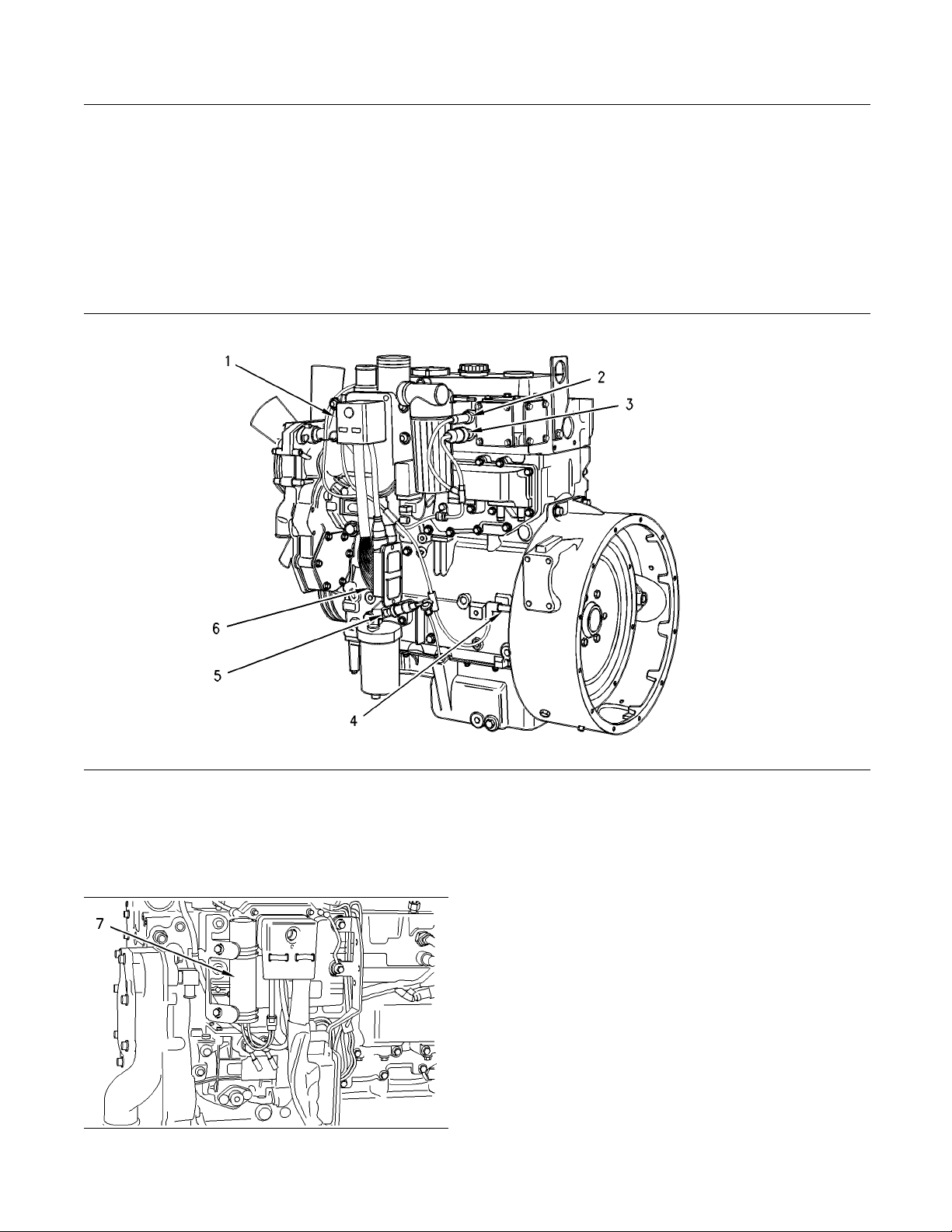
g00765012
Illustration 7
Use the example above. The current flow from the w elder to
the ground clamp of the welder will not cause damage to any
associated components.
(1) Engine
(2) Welding rod
(3) Keyswitch in the OFF position
(4) Battery disconnect switch in the open position
(5) Disconnected battery cables
(6) Battery
(7) Electrical/Electronic component
(8) Maximum distance between the component that is being
welded and any electrical/electronic component
(9) The com ponent that is being welded
(10) Current path of the welder
(11) Ground clamp for the welder
4. Connect the welding ground cable directly to the
part that will be welded. Place the ground cable as
close as possible to the weld in order to reduce the
possibility of welding current damage to bearings,
hydraulic components, electrical components, and
ground straps.
Note: If electrical/electronic components are used
as a ground for the welder, or electrical/electronic
components are located between the welder ground
and the weld, current flow from the welder could
severely damage the component.
5. Protect the wiring harness from welding debris
and spatter.
6. Use standard welding practices to weld the
materials.
SEBU8121 13
Product Information Section
Model Views
Model Views
i02247468
Model View Illustrations
1104 Engine Vi
ews
g01131700
Illustration 8
Left side view of the 1104 engine
Typical example of the 1104 engine
14 SEBU8121
Product Information Section
Model Views
(1) Fuel lines
(2) Fuel primin
g pump
(3) Fuel filter
(4) Machine int
erface connector (MIC)
(5) Speed/timin
gsensor
(6) Electronic f
uel injection pump
(7) Engine oil pr
essure sensor
(8) Engine oil f
ilter
(9) Water pump
(10) Crankshaf
t pulley
(11) Alternato
r
(12) Engine cool
ant temperature sensor
(13) Voltage loa
d protection module
(14) Electronic
control module (ECM)
g01131701
Illustration 9
Right side view of the 1104 engine
Typical example of the 1104 engine
(1) Exhaust elbow
(2) Turbocharger
(3) Wastegate actuator
(4) Starter motor
(5) Flywheel housing
SEBU8121 15
Product Information Section
Model Views
i02247483
Engine Description
The Perkins110
4 Electronic Engine is designed for
the following applications: machine and industrial
mobile equipment. The engines are available in the
following typ
es of aspiration:
•
Turbocharged aftercooled
•
Turbocharged
•
Naturally asp
irated
Engine Specif
ications
Note: The front end of the engine is opposite the
flywheel end
of the engine. The left and the right
sides of the engine are determined from the flywheel
end. The number 1 cylinder is the front cylinder.
g00984281
Illustration 10
Typical example
1104 Electronic engine
(A) Inlet valves
(B) Exhaust valves
Table 1
1104 Electronic Engine Specifications
Number of Cylinders 4 In-Line
Bore
105 mm (4.134 inch)
Stroke 127 mm (5.0 inch)
Aspiration
Turbocharged, aftercooled
Turbocharged
Naturally aspirated
Compression
Ratio
NA 19.25:1 NA
T 18.23:1 T, TA
Displacement
4.4L(268in
3
)
Firing Order 1-3-4-2
Rotation (flywheel end) Counterclockwise
Valve Lash Setting (Inlet) 0.20 mm (0.008 inch)
Valve Lash Setting
(Exhaust)
0.45 mm (0.018 inch)
E
lectronic Engine Featur es
The Perkins 1104 Electronic Engine is designed with
e
lectronic controls. The integral on board computer
controls the operation of the engine. Current
operating conditions are monitored. The Electronic
Control Module (ECM) controls the response of the
engine to these conditions and to the demands of the
operator. These conditions and operator demands
determine the precise control of fuel injection by the
ECM. The electronic engine control system provides
the following features:
•
Engine monitoring
•
Engine speed governing
•
Cold start strategy
•
Automatic air/fuel ratio control
•
Torque rise shaping
•
Automatic altitude compensation
•
Fuel temperature compensation
•
Injection timing control
•
System diagnostics
For more information on electronic engine features,
refer to the Operation and Maintenance Manual,
“Features and Controls” topic (Operation Section).

16 SEBU8121
Product Information Section
Model Views
Engine Diagnostics
The Perkins 110
4 engine has built-in diagnostics
in order to ensure that all of the components are
functioning properly. The operator will be informed of
anychangetoa
programmed limit. The operator will
be alerted to the condition by a “Stop or Warning”
lamp that may be mounted on the dashboard or
on the contro
l panel. Under certain conditions, the
engine horsepower and the vehicle speed may be
limited. The electronic service tool may be used to
display the d
iagnostic codes.
There are three types of diagnostic codes: active,
logged, and
event.
Most of the diagnostic codes are logged and stored
in the ECM. F
or additional information, refer to
the Operation and Maintenance Manual, “Engine
Diagnostics” topic (Operation Section).
The ECM provides an electronic governor that
controls the injector output in order to maintain the
desired en
gine rpm.
Engine Coo
ling and Lubrication
The cooling system consists of the following
component
s:
•
Gear-driven centrifugal water pump
•
Water temperature regulators which regulate the
engine coolant temperature
•
Gear-driven oil pump (gear type)
•
Oil cooler
The engine lubricating oil is supplied by a gear
type pump
. The engine lubricating oil is cooled and
the engine lubricating oil is filtered. Bypass valves
provide unrestricted flow of lubrication oil to the
engine pa
rts when oil viscosity is high. Bypass valves
can also provide unrestricted flow of lubrication oil
to the engine parts if the oil cooler should become
plugged
or if the oil filter element should become
plugged.
Engine e
fficiency, efficiency of emission controls, and
engine performance depend on adherence to proper
operation and maintenance recommendations.
Engine p
erformance and efficiency also depend on
the use of recommended fuels, lubrication oils, and
coolants. Refer to the Operation and Maintenance
Manual
, “Maintenance Interval Schedule” for more
information on maintenance items.
Engine Service Life
Engine efficiency and maximum utilization of engine
performance depend on the adherence to proper
operation and maintenance recommendations. In
addition, use recommended fuels, coolants and
lubricants. Use the Operation and Maintenance
Manual as a guide for required engine maintenance.
Expected engine life is generally predicted by the
average power that is demanded. The average power
that is demanded is based on fuel consumption of
the engine over a period of time. Reduced hours of
operation at full throttle and/or operating at reduced
throttle settings result in a lower average power
demand. Reduced hours of operation will increase
the length of operating time before an engine
overhaul is required.
SEBU8121 17
Product Information Section
Product Identification Information
Product Identification
Information
i02280116
Engine Identification
Perkins engines are identified by a serial number.
This number is shown on a serial number plate that
is mounted on the left hand side of the engine block.
An example of an engine number is
RE12345U090001H.
RE
_______________________________________ ___ Type of engine
RE12345
____________________________ Engine List Number
U
____________________________Built in the United Kingdom
090001
___________________________Engine Serial Number
H
________________________________ _____ Year of Manufacture
Perkins dealers need these numbers in order to
determine the components that were included with
the engine. This permits accurate identification of
replacement part numbers.
i01940474
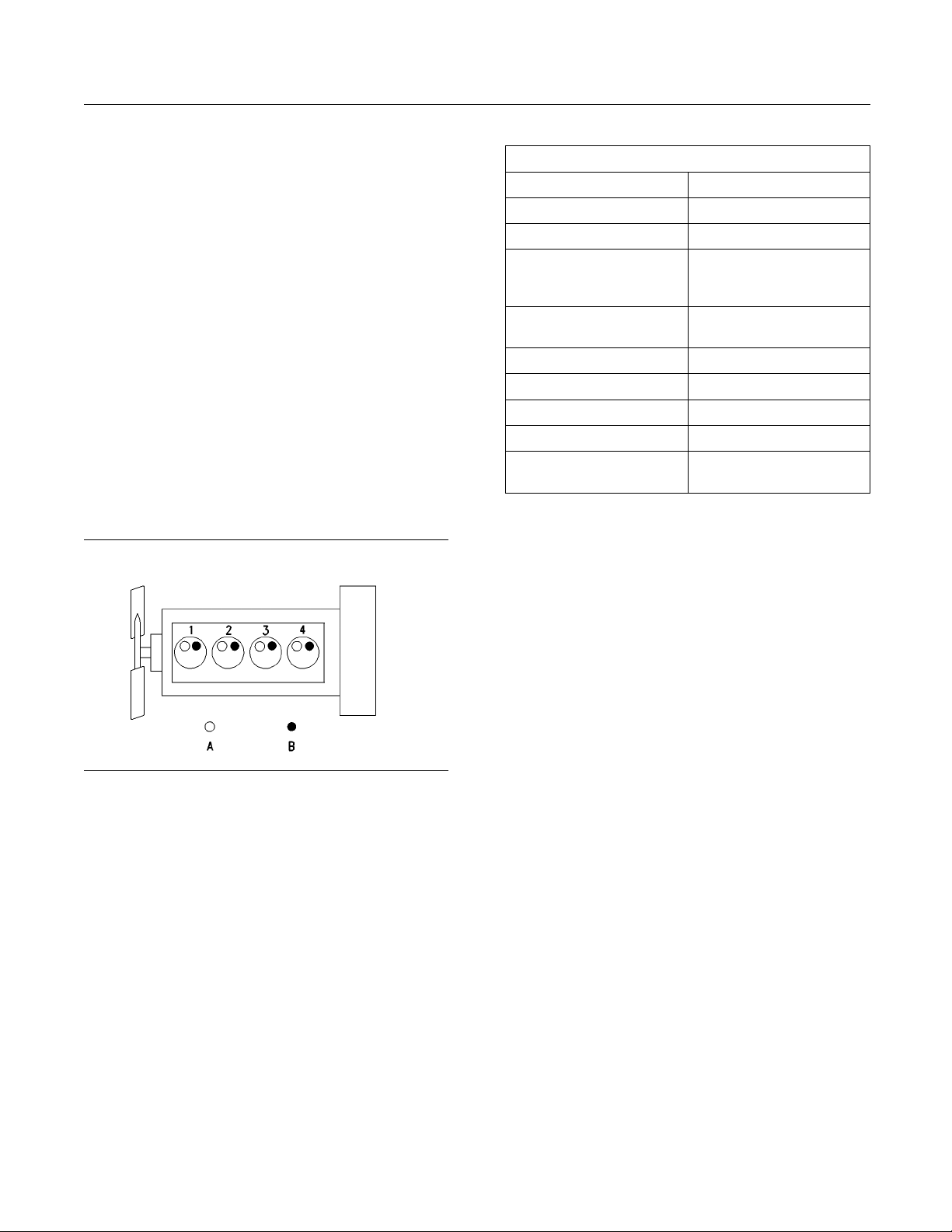
Serial Number Plate
g00994966
Illustration 11
Typical serial number plate
(1) Temporary Parts List number
(2) Type
(3) Serial number
(4) List number
The Serial Number Plate is located on the left side of
the cylinder block behind the high pressure pipes of
the Fuel injection pump.
The following information is stamped on the Serial
Number Plate: Engine serial number, Model, and
Arrangement number.
i02164876
Reference N umbers
Information for the following items may be needed to
order parts. Locate the information for your engine.
Record the information in the appropriate space.
Make a copy of this list for a record. Keep the
information for future reference.
Record for Reference
Engine Model _______________________________________________
Engine Serial number ____ _________________________________
Engine Low Idle rpm ______________________________________
18 SEBU8121
Product Information Section
Product Identification Information
Engine Full Loa
drpm
_____________________________________
Primary Fuel Filter _________________________________________
Water Separator Element ________________________________
Secondary Fue
l Filter Element
__________________________
Lubrication Oil Filter Element ___________________________
Auxiliary Oil Filter Element _______________________________
Total Lubrica
tion System Capacity
_____________________
Total Cooling System Capacity _________________________
Air Cleaner Element ______ _________________________________
Fan Drive Belt
______________________________________________
Alternator Belt ______________________________________________
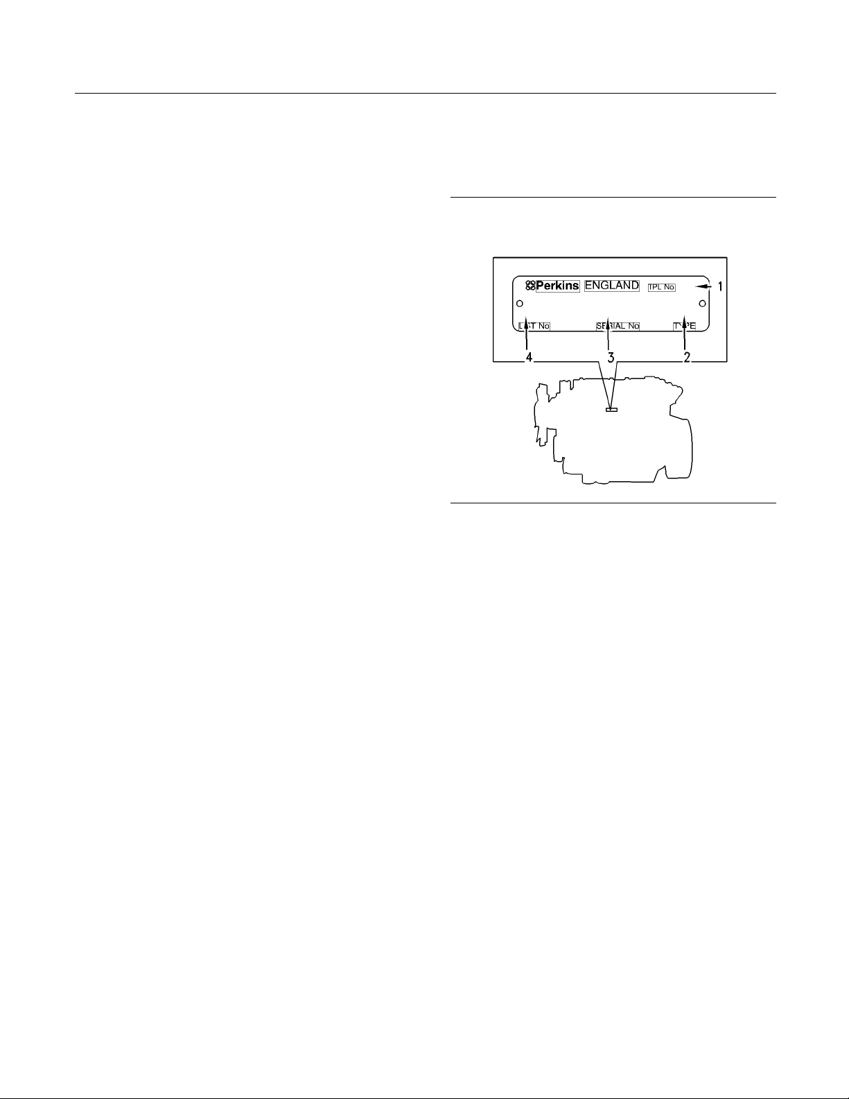
i02272778
Emissions Certification Film
Label for compliant engines
g01127835
Illustration 12
Typical example
This label is installed on engines that com ply with em issions.
SEBU8121 19
Operation Section
Lifting and Storage
Operation Section
Lifting and Storage
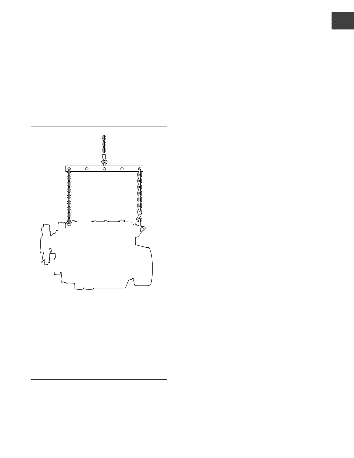
i02164186
Engine Lifting
g01097527
Illustration 13
NOTICE
Never bend the eyebolts and the brackets. Only load
the eyeb
olts and the brackets under tension. Remem-
ber that the capacity of an eyebolt is less as the angle
between the supporting members and the object be-
comes le
ss than 90 degrees.
When it is necessary to remove a component at an
angle, o
nly use a link bracket that is properly rated for
the weight.
Use a ho
ist to remove heavy components. Use
an adjustable lifting beam to lift the engine. All
supporting members (chains and cables) should be
parall
el to each other. The chains and cables should
be perpendicular to the top of the object that is being
lifted.
Some removals r
equire lifting the fixtures in order to
obtain correct balance and safety.
To r e mov e th e e
ngine ONLY, use the lifting eyes that
are on the engine.
Lifting eyes a
re designed and installed for specific
engine arrangements. Alterations to the lifting eyes
and/or the engine make the lifting eyes and the lifting
fixtures obs
olete. If alterations are made, ensure
that correct lifting devices are provided. Consult
your Perkins dealer or your Perkins distributor for
information
regarding fixtures for correct engine
lifting.
i02248407
Engine Storage
If the engine will not be started for several weeks, the
lubricating oil will drain from the cylinder walls and
from the piston rings. Rust can form on the cylinder
walls. Rust on the cylinder walls will cause increased
engine wear and a reduction in engine service life.
Lubrication System
To help prevent excessive engine wear, use the
following guidelines:
Complete all of the lubrication recommendations that
are listed in this Operation and Maintenance Manual,
“Maintenance Interval Schedule” (Maintenance
Section).
If an engine is out of operation and if use of the engine
is not planned, special precautions should be made.
If the engine will be stored for more than one month,
a complete protection procedure is recommended.
Use the following guidelines :
•
Completely clean the outside of the engine.
•
Drain the fuel system completely and refill
the system with preservative fuel.1772204
POWERPARTLay-Up1canbemixedwith
the normal fuel in order to change the fuel into
preservative fuel.
•
If preservative fuel is not available, the fuel system
canbefilledwithnormalfuel.Thisfuelmustbe
discarded at the end of the storage period together
with the fuel filter elements.
•
Operate the engine until the engine reaches
normal operating temperature. Stop any leaks from
fuel, lubricating oil or air systems. Stop the engine
and drain the lubricating oil from the oil pan.
20 SEBU8121
Operation Section
Lifting and Storage
•
Renew the canis
ter(s) of the lubricating oil filter.
•
Fill the oil pan to the Full Mark on the dipstick
with new, clea
n lubricating oil. Add 1762811
POWERPARTLay-Up2totheoilinorderto
protect the engine against corrosion. If 1762811
POWERPART La
y-Up 2 is not available, use a
preservative of the correct specification instead
of the lubricating oil. If a preservative is used,
this must be d
rained completely at the end of the
storage period and the oil pan must be refilled to
the correct level with normal lubricating oil.
Cooling System
To help prevent excessive engine wear, use the
following guidelines:
NOTICE
Do not drain the coolant while the engine is still hot and
the system is under pressure because dangerous hot
coolant can
be discharged.
If freezing temperatures are expected, check the
cooling sys
tem for adequate protection against
freezing. See this Operation and Maintenance
Manual, “General Coolant Information” (Maintenance
Section).
NOTICE
To prevent frost damage, ensure that all the coolant is
removed fr
om the engine. This is important if the sys-
tem is drained after it has been flushed with water, or if
an antifreeze solution too weak to protect the system
from frost
has been used.
g010039
28
Illustration 14
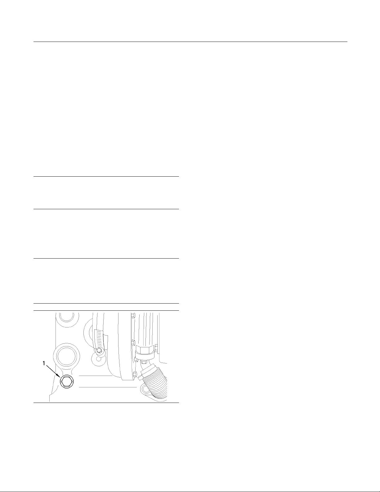
1. Ensure that the engine is on level ground.
2. Remove t
he filler cap of the cooling system.
3. Remove the drain plug (1) from the side of the
cylinde
r block in order to drain the engine. Ensure
that the drain hole is not restricted.
4. Open the tap or r
emove the drain plug at the
bottom of the radiator in order to drain the radiator.
If the radiator does not have a tap or a drain plug,
disconnect th
e hose at the bottom of the radiator.
5. Flush the cooling system with clean water.
6. Fit the drain plugs and the filler cap. Close the tap
or connect the radiator hose.
7. Fill the cooling system with an approved
antifreeze mixture because this gives protection
against corr
osion. The maximum flow rate is 1 L
(0.2200 Imp gal) per minute in order to fill the
system.
Note: Certain corrosion inhibitors could cause
damage to some engine components. Contact the
Service Dep
artment of Perkins for advice.
8. Operate the engine for a short period in order to
circulate t
he lubricating oil and the coolant in the
engine.
9. Disconnect
the battery. Put the battery into safe
storage in a fully charged condition. Before the
battery is put into storage, protect the terminals
against co
rrosion.1734115 POWERPART Lay-Up
3 can be used on the terminals.
10. Clean the c
rankcase breather if one is installed.
Seal the end of the pipe.
11. Remove the
fuel injector nozzles and spray
1762811 POWERPART Lay-Up 2 for one or two
seconds into each cylinder bore with the piston
at BDC.
12. Slowly rotate the crankshaft for one complete
revoluti
on and then replace the fuel injector
nozzles.
Induction System
•
Remove th
e air filter assembly. If necessary,
remove the pipes that are installed between
the air filter assembly and the turbocharger.
Spray 17
62811 POWERPARTLay-Up2intothe
turbocharger. The duration of the spray is printed
on the container. Seal the turbocharger with
waterpr
oof tape.
Exhaust
System
•
Remove the exhaust pipe. Spray 1762811
POWERP
ART Lay-Up 2 into the turbocharger. The
duration of the spray is printed on the container.
Seal the turbocharger with waterproof tape.

SEBU8121 21
Operation Section
Lifting and Storage
General Items
•
If the lubricating oil filler is installed on the rocker
cover, remove the filler cap. If the lubricating oil filler
cap is not installed on the rocker cover, remove
the rocker cover. Spray 1762811 POWERPART
Lay-Up 2 around the rocker shaft assembly.
Replace the filler cap or the rocker cover.
•
Seal the vent of the fuel tank or the fuel filler cap
with waterproof tape.
•
Remove the alternator drive belts and put the drive
belts into storage.
•
In order to prevent corrosion, spray the engine with
1734115 POWERPART Lay-Up 3. Do not spray
the area inside the alternator.
When the engine protection has been completed in
accordance with these instructions, this ensures that
no corrosion will occur. Perkins are not responsible
for damage which may occur when an engine is in
storage after a period in service.
Your Perkins dealer or your Perkins distributor can
assist in preparing the engine for extended storage
periods.
22 SEBU8121
Operation Section
Gauges and Indicators
Gauges an d Indicators
i02164190
Gauges and Indicators
Your engine m
ay not have the same gauges or all of
the gauges that are described. For more information
about the gauge package, see the OEM information.
Gauges provide indications of engine performance.
Ensure that the gauges are in good working order.
Determine th
e normal operating range by observing
the gauges over a period of time.
Noticeable c
hanges in gauge readings indicate
potential gauge or engine problems. Problems may
also be indicated by gauge readings that change
even if the r
eadings are within specifications.
Determine and correct the cause of any significant
change in the readings. Consult your Perkins dealer
or your Per
kins distributor for assistance.
NOTICE
If no oil pressure is indicated, STOP the engine. If
maximum co
olant temperature is exceeded, STOP
the engine. Engine damage can result.
Engine Oil
Pressure – The oil pressure
should be greatest after a cold engine is
started. The typical engine oil pressure with
SAE10W30
is 207 to 413 kPa (30 to 60 psi) at rated
rpm.
A lower oil pressure is normal at low idle. If the load
is stable
and the gauge reading changes, perform
the following procedure:
1. Remove th
e load.
2. Reduce engine speed to low idle.
3. Check and maintain the oil level.
Jacket Wa
ter Coolant Temperature –
Typical temperature range is 71 to 96°C
(160 to 205°F). The maximum allowable
tempera
ture w ith the pressurized cooling system at
48 kPa (7 psi) is 110°C (230°F). Higher temperatures
may occur under certain conditions. The water
tempera
ture reading may vary according to load. The
reading should never exceed the boiling point for the
pressurized system that is being used.
If the en
gine is operating above the normal range
and steam becomes apparent, perform the following
procedure:
1. Reduce the load
and the engine rpm.
2. Inspect the cooling system for leaks.
3. Determine if the engine must be shut down
immediately or if the engine can be cooled by
reducing the l
oad.
Tachometer – This gauge indicates engine
speed (rpm). W
hen the throttle control lever
ismovedtothefullthrottlepositionwithout
load, the engine is running at high idle. The engine is
running at th
efullloadrpmwhenthethrottlecontrol
lever is at the full throttle position with maximum
rated load.
NOTICE
To help prevent engine damage, never exceed the
high idle rpm. Overspeeding can result in serious
damage to the engine. The engine can be operated
at high idle without damage, but should never be
allowedtoexceedhighidlerpm.
Ammeter – This gauge indicates the
amount of charge or discharge in the
battery charging circuit. Operation of the
indicator should be to the right side of “0” (zero).
Fuel Level – This gauge indicates the fuel
level in the fuel tank. The fuel level gauge
operates when the “START/STOP” switch
is in the “ON” position.
Service Hour Meter – The gauge indicates
operating time of the engine.
SEBU8121 23
Operation Section
Features and Controls
Features and Controls
i02259828
Monitoring System
If the Shutdown mode has been selec ted and the
warning indi
cator activates, engine shutdown may
take as little as 20 seconds from the time the warn-
ing indicator is activated. Depending on the ap-
plication, s
pecial precautions should be taken to
avoid personal injury. The engine can be restarted
following shutdown for emergency maneuvers, if
necessary.
NOTICE
The Engine Monitoring System is not a guarantee
against catastrophic failures. Programmed delays
and derate schedules are designed to minimize false
alarms and provide time for the operator to stop the
engine.
The following parameters are monitored:
•
Coolant temperature
•
Intake manifold air temperature
•
Intake manifold air pressure
•
Oil pressure
•
Fuel temperature
•
Engine speed/timing
Programmable Options and
Systems Operation
If the Warning/Derate/Shutdown mode has been
selected and the warning indicator activates,
bring the engine to a stop whenever possible. De-
pending on the a pplication, special precautions
should be taken to avoid personal injury.
The engine can be programmed to the following
modes:
“Warning”
The “Warning” lamp and the warning signal (orange
lamp) turn “ON
” and the warning signal is activated
continuously in order to alert the operator that one or
more of the engine parameters is not within normal
operating ra
nge.
“Warning/Derate”
The “Diagnostic” lamp turns “ON” and the warning
signal (red lamp) is activated. After the warning, the
engine power
will be derated. The warning lamp will
begin to flash when the derating occurs.
Theenginewi
ll be derated if the engine exceeds
preset operational limits. The engine derate is
achieved by restricting the amount of fuel that is
available f
or each injection. The amount of this
reduction of fuel is dependent on the severity of the
fault that has caused the engine derate, typically up
to a limit o
f 50%. This reduction in fuel results in a
predetermined reduction in engine power.
“Warning/
Derate/Shutdown”
The “Diagnostic” lamp turns “ON” and the warning
signal (re
d lamp) is activated. After the warning,
the engine power will be derated. The engine will
continue at the rpm of the set derate until a shutdown
of the engi
ne occurs. The engine can be restarted
after a shutdown for use in an emergency.
A shutdow
n of the engine may occur in as little
as 20 seconds. The engine can be restarted after
a shutdown for use in an emergency. However,
the cause
of the initial shutdown may still exist.
Theenginemayshutdownagaininaslittleas20
seconds.
If there is a signal for low oil pressure or for coolant
temperature, there will be a two second delay in
order to
verify the condition.
For each of the programmed modes, refer to
Trouble
shooting Guide, “Indicator Lamps” for more
information on Indicator Lamps.
For more
information or assistance for repairs, consult
your Perkins dealer or your Perkins distributor.
24 SEBU8121
Operation Section
Features and Controls
i02259829
Sensors and Electrical
Components
Sensor Locations for the 1104
Engine
g00894185
Illustration 15
Left side view of the 1104 engine
Typical example of a 1104 engine
(1) Electronic control module (ECM)
(2) Intake manifold temperature sensor
(3) Intake manifold pressure sensor
(4) Speed/timing sensor
(5) Engine oil pre ssure sensor
(6) Machine interface connector
g00915
275
Illustration 16
(7) Typical location of the voltage load protection module by the
ECM
SEBU8121 25
Operation Section
Features and Controls
g00915291
Illustration 17
Right side
view of the 1104 engine
Typical example of a 1104 engine
(8) Engine coolant temperature sensor
Failure of Sensors
All Senso
rs
A failure of any of the sensors may be caused by one
of the fol
lowing malfunctions:
•
Sensor output is open.
•
Sensor output is shorted to “- battery” or “+ battery”.
•
Measured
reading of the sensor is out of the
specification.
Intake Manifold Pressure Sensor
The inta
ke manifold pressure sensor provides a
signal which corresponds to the intake manifold
pressure to the ECM. The ECM can control injection
timing a
nd the amount of fuel that is injected.
When the throttle is increased and when the engine
demands more fuel, the fuel limit is controlled in order
to redu
ce overall smoke levels of the engine exhaust.
Engine Oil Pressure Sensor
The engin
e oil pressure sensor is an absolute
pressure sensor that measures the engine oil
pressure in the main oil gallery. The engine oil
pressur
e sensor detects engine oil pressure for
diagnostic purposes. The engine oil pressure sensor
sendsasignaltotheECM.
Intake Manifold Temperature
Sensor
The inta
ke manifold temperature sensor measures
the inlet air temperature. A signal is sent to the
Electronic Control Module (ECM). The intake
manifo
ld temperature sensor is also used by the
ECM to determine initiation of the Cold Start Strategy
and control for appropriate start of injection timing
while t
he engine is warming up.

26 SEBU8121
Operation Section
Features and Controls
Coolant Temperature Sensor
The coolant temperature sensor monitors the engine
coolant temperature. The output of the ECM can
indicate a high coolant temperature through a relay
or a lamp. The coolant temperature sensor is used
by the ECM to determine initiation of the Cold Start
Condition and control for appropriate start of injection
timing while the engine is warming up.
Speed/Timing Sensor
If the ECM does not receive a signal from the primary
speed/timing sensor the “DIAGNOSTIC” lamp will
indicate a diagnostic fault code which will be logged
in the ECM memory.
If the ECM does not receive a signal from the primary
speed/timing sensor, the ECM will read the signal
from the secondary speed/timing sensor. The ECM
continually checks in order to determine if there is a
signal from both sensors. If either sensor fails, the
faulty sensor should be replaced.
Intermittent failure of the sensors will cause erratic
engine control.
Throttle Position Sensor
The throttle position sensor (TPS) eliminates the
mechanical throttle and governor linkages. The TPS
interprets the position of the throttle lever into an
electrical signal that is sent to the ECM. The throttle
position signal and the engine speed/timing signal
are processed by the ECM in order to precisely
control engine speed.
 Loading...