


SEBU8604
March 2010
Operation and
Maintenance
Manual
4016-61 TRG Industrial Engine
S16 (Engine)

Important Safety Information
Most accidents that involve product operation, maintenance and repair are caused by failure to observe basic safety rules or precautions. An accident can often be avoided by recognizing potentially hazardous situations before an accident occurs. A person must be alert to potential hazards. This person should also have the necessary training, skills and tools to perform these functions properly.
Improper operation, lubrication, maintenance or repair of this product can be dangerous and could result in injury or death.
Do not operate or perform any lubrication, maintenance or repair on this product, until you have read and understood the operation, lubrication, maintenance and repair information.
Safety precautions and warnings are provided in this manual and on the product. If these hazard warnings are not heeded, bodily injury or death could occur to you or to other persons.
The hazards are identified by the “Safety Alert Symbol” and followed by a “Signal Word” such as “DANGER”, “WARNING” or “CAUTION”. The Safety Alert “WARNING” label is shown below.
The meaning of this safety alert symbol is as follows:
Attention! Become Alert! Your Safety is Involved.
The message that appears under the warning explains the hazard and can be either written or pictorially presented.
Operations that may cause product damage are identified by “NOTICE” labels on the product and in this publication.
Perkins cannot anticipate every possible circumstance that might involve a potential hazard. The warnings in this publication and on the product are, therefore, not all inclusive. If a tool, procedure, work method or operating technique that is not specifically recommended by Perkins is used,
you must satisfy yourself that it is safe for you and for others. You should also ensure that the product will not be damaged or be made unsafe by the operation, lubrication, maintenance or repair procedures that you choose.
The information, specifications, and illustrations in this publication are on the basis of information that was available at the time that the publication was written. The specifications, torques, pressures, measurements, adjustments, illustrations, and other items can change at any time. These changes can affect the service that is given to the product. Obtain the complete and most current information before you start any job. Perkins dealers or Perkins distributors have the most current information available.
When replacement parts are required for this product Perkins recommends using Perkins replacement parts.
Failure to heed this warning can lead to premature failures, product damage, personal injury or death.

SEBU8604 |
3 |
|
Table of Contents |
|
|
Table of Contents |
|
Foreword ................................................................. |
4 |
Safety Section |
|
Safety Messages .................................................... |
5 |
General Hazard Information ................................... |
5 |
Burn Prevention ...................................................... |
7 |
Fire Prevention and Explosion Prevention .............. |
7 |
Crushing Prevention and Cutting Prevention .......... |
9 |
Mounting and Dismounting ..................................... |
9 |
Before Starting Engine .......................................... |
10 |
Engine Starting ..................................................... |
10 |
Engine Stopping ................................................... |
10 |
Electrical System ................................................... |
11 |
Engine Electronics ................................................. |
11 |
Product Information Section |
|
General Information .............................................. |
12 |
Model Views ......................................................... |
13 |
Product Identification Information ........................ |
17 |
Operation Section |
|
Lifting and Storage ................................................ |
19 |
Features and Controls .......................................... |
22 |
Engine Starting ..................................................... |
26 |
Engine Operation .................................................. |
28 |
Engine Stopping ................................................... |
29 |
Maintenance Section |
|
Refill Capacities .................................................... |
30 |
Maintenance Interval Schedule ............................ |
42 |
Warranty Section |
|
Index Section
Index ..................................................................... |
77 |
Warranty Information ............................................ |
76 |
4 |
SEBU8604 |
Foreword |
|
|
|
Foreword
Literature Information
This manual contains safety, operation instructions, lubrication and maintenance information. This manual should be stored in or near the engine area in a literature holder or literature storage area. Read, study and keep it with the literature and engine information.
English is the primary language for all Perkins publications. The English used facilitates translation and consistency.
Some photographs or illustrations in this manual show details or attachments that may be different from your engine. Guards and covers may have been removed for illustrative purposes. Continuing improvement and advancement of product design may have caused changes to your engine which are not included in this manual. Whenever a question arises regarding your engine, or this manual, please consult with your Perkins dealer or your Perkins distributor for the latest available information.
Safety
This safety section lists basic safety precautions. In addition, this section identifies hazardous, warning situations. Read and understand the basic precautions listed in the safety section before
operating or performing lubrication, maintenance and repair on this product.
Operation
Operating techniques outlined in this manual are basic. They assist with developing the skills and techniques required to operate the engine more efficiently and economically. Skill and techniques develop as the operator gains knowledge of the engine and its capabilities.
The operation section is a reference for operators. Photographs and illustrations guide the operator through procedures of inspecting, starting, operating and stopping the engine. This section also includes a discussion of electronic diagnostic information.
Maintenance
The maintenance section is a guide to engine care. The illustrated, step-by-step instructions are grouped by service hours and/or calendar time maintenance intervals. Items in the maintenance schedule are referenced to detailed instructions that follow.
Recommended service should be performed at the appropriate intervals as indicated in the Maintenance Interval Schedule. The actual operating environment of the engine also governs the Maintenance Interval Schedule. Therefore, under extremely severe, dusty, wet or freezing cold operating conditions, more frequent lubrication and maintenance than is specified in the Maintenance Interval Schedule may be necessary.
The maintenance schedule items are organized for a preventive maintenance management program. If the preventive maintenance program is followed, a periodic tune-up is not required. The implementation of a preventive maintenance management program should minimize operating costs through cost avoidances resulting from reductions in unscheduled downtime and failures.
Maintenance Intervals
Perform maintenance on items at multiples of the original requirement. We recommend that the
maintenance schedules be reproduced and displayed near the engine as a convenient reminder. We also recommend that a maintenance record be maintained as part of the engine's permanent record.
Your authorized Perkins dealer or your Perkins distributor can assist you in adjusting your maintenance schedule to meet the needs of your operating environment.
Overhaul
Major engine overhaul details are not covered in the Operation and Maintenance Manual except for the interval and the maintenance items in that
interval. Major repairs should only be carried out by Perkins authorized personnel. Your Perkins dealer or your Perkins distributor offers a variety of options regarding overhaul programs. If you experience
a major engine failure, there are also numerous after failure overhaul options available. Consult with your Perkins dealer or your Perkins distributor for information regarding these options.
California Proposition 65 Warning
Diesel engine exhaust and some of its constituents are known to the State of California to cause cancer, birth defects, and other reproductive harm. Battery posts, terminals and related accessories contain lead and lead compounds. Wash hands after handling.
SEBU8604 |
5 |
|
Safety Section |
|
Safety Messages |
Safety Section
i03835895
Safety Messages
There may be several specific warning signs on your engine. The exact location and a description of the warning signs are reviewed in this section. Please become familiar with all warning signs.
Ensure that all of the warning signs are legible. Clean the warning signs or replace the warning signs if the words cannot be read or if the illustrations are not visible. Use a cloth, water, and soap to clean the warning signs. Do not use solvents, gasoline, or other harsh chemicals. Solvents, gasoline, or harsh chemicals could loosen the adhesive that secures the warning signs. The warning signs that are loosened could drop off of the engine.
Replace any warning sign that is damaged or missing. If a warning sign is attached to a part of the engine that is replaced, install a new warning sign on the replacement part. Your Perkins dealer or your distributor can provide new warning signs.
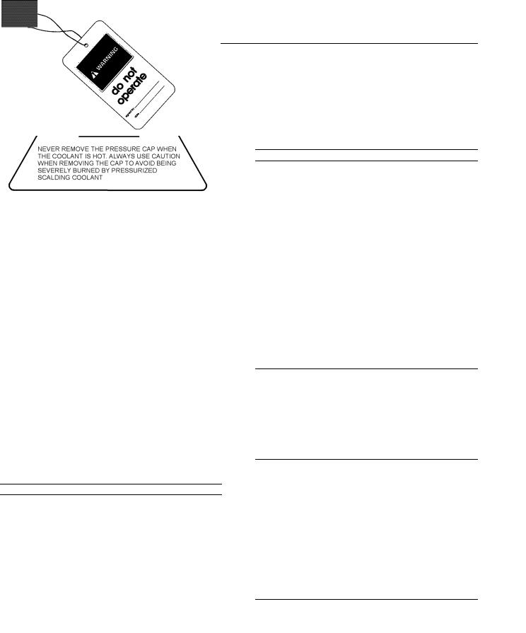
(1) Universal Warning
Do not operate or work on this equipment unless you have read and understand the instructions and warnings in the Operation and Maintenance Manuals. Failure to follow the instructions or heed the warnings could result in serious injury or death.
(2) Hot Coolant
Pressurized system: Hot coolant can cause serious burn. To open cap, stop engine, wait until radiator is cool. Then loose the cap slowly to relieve the pressure.
Illustration 2 |
g01231165 |
|
|
|
i02328435 |
General Hazard Information
|
|
Illustration 3 |
g00104545 |
|
|
|
|
|
|
Attach a “Do Not Operate” warning tag or a similar |
|
Illustration 1 |
g01231164 |
warning tag to the start switch or to the controls |
|
|
before you service the equipment or before you |
||
|
|
||
repair the equipment.
6 |
SEBU8604 |
Safety Section |
|
General Hazard Information |
|
Illustration 4 |
g00702020 |
|
Wear a hard hat, protective glasses, and other protective equipment, as required.
Do not wear loose clothing or jewelry that can snag on controls or on other parts of the engine.
Make sure that all protective guards and all covers are secured in place on the engine.
Keep the engine free from foreign material. Remove debris, oil, tools, and other items from the deck, from walkways, and from steps.
Never put maintenance fluids into glass containers. Drain all liquids into a suitable container.
Obey all local regulations for the disposal of liquids.
Use all cleaning solutions with care.
Report all necessary repairs.
Do not allow unauthorized personnel on the equipment.
Ensure that the power supply is disconnected before you work on the bus bar or the glow plugs.
Perform maintenance on the engine with the equipment in the servicing position. Refer to the OEM information for the procedure for placing the equipment in the servicing position.
Pressure Air and Water
Pressurized air and/or water can cause debris and/or hot water to be blown out. This could result in personal injury.
The direct application of pressurized air or pressurized water to the body could result in personal injury.
When pressurized air and/or water is used for cleaning, wear protective clothing, protective shoes, and eye protection. Eye protection includes goggles or a protective face shield.
The maximum air pressure for cleaning purposes must be below 205 kPa (30 psi). The maximum water pressure for cleaning purposes must be below 275 kPa (40 psi).
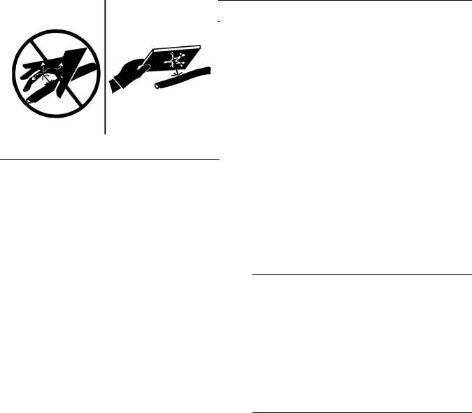
Fluid Penetration
Pressure can be trapped in the hydraulic circuit long after the engine has been stopped. The pressure can cause hydraulic fluid or items such as pipe plugs to escape rapidly if the pressure is not relieved correctly.
Do not remove any hydraulic components or parts until pressure has been relieved or personal injury may occur. Do not disassemble any hydraulic components or parts until pressure has been relieved or personal injury may occur. Refer to the OEM information for any procedures that are required to relieve the hydraulic pressure.
Illustration 5 |
g00687600 |
|
Always use a board or cardboard when you check for a leak. Leaking fluid that is under pressure can penetrate body tissue. Fluid penetration can cause serious injury and possible death. A pin hole leak can cause severe injury. If fluid is injected into your skin, you must get treatment immediately. Seek treatment from a doctor that is familiar with this type of injury.
Containing Fluid Spillage
Care must be taken in order to ensure that fluids are contained during performance of inspection, maintenance, testing, adjusting and repair of the engine. Make provision to collect the fluid with a suitable container before any compartment is opened or before any component is disassembled.
•Only use the tools that are suitable for collecting fluids and equipment that is suitable for collecting fluids.
SEBU8604 |
7 |
|
Safety Section |
|
Burn Prevention |
•Only use the tools that are suitable for containing fluids and equipment that is suitable for containing fluids.
Obey all local regulations for the disposal of liquids.
i02334785
Burn Prevention
Oils
Hot oil and hot lubricating components can cause personal injury. Do not allow hot oil to contact the skin. Also, do not allow hot components to contact the skin.
Batteries
Do not touch any part of an operating engine. Allow the engine to cool before any maintenance is performed on the engine.
Contact with high pressure fuel may cause fluid penetration and burn hazards. High pressure fuel spray may cause a fire hazard. Failure to follow these inspection, maintenance and service instructions may cause personal injury or death.
After the engine has stopped, you must wait for 60 seconds in order to allow the fuel pressure to be purged from the high pressure fuel lines before any service or repair is performed on the engine fuel lines.
Allow the pressure to be purged in the air system, in the hydraulic system, in the lubrication system, or in the cooling system before any lines, fittings or related items are disconnected.
Coolant
When the engine is at operating temperature, the engine coolant is hot. The coolant is also under pressure. The radiator and all lines to the heaters or to the engine contain hot coolant.
Any contact with hot coolant or with steam can cause severe burns. Allow cooling system components to cool before the cooling system is drained.
Check the coolant level after the engine has stopped and the engine has been allowed to cool.
Ensure that the filler cap is cool before removing the filler cap. The filler cap must be cool enough to touch with a bare hand. Remove the filler cap slowly in order to relieve pressure.
Cooling system conditioner contains alkali. Alkali can cause personal injury. Do not allow alkali to contact the skin, the eyes, or the mouth.
Electrolyte is an acid. Electrolyte can cause personal injury. Do not allow electrolyte to contact the skin or the eyes. Always wear protective glasses for servicing batteries. Wash hands after touching the batteries and connectors. Use of gloves is recommended.
i02320721
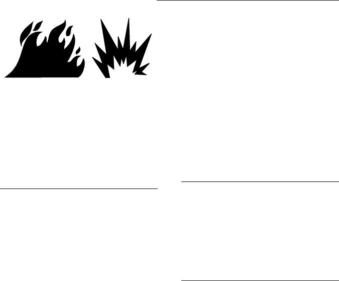
Fire Prevention and Explosion Prevention
Illustration 6 |
g00704000 |
|
All fuels, most lubricants, and some coolant mixtures are flammable.
Flammable fluids that are leaking or spilled onto hot surfaces or onto electrical components can cause a fire. Fire may cause personal injury and property damage.
After the emergency stop button is operated ensure that you allow 15 minutes, before the engine covers are removed.
Determine whether the engine will be operated in an environment that allows combustible gases to be drawn into the air inlet system. These gases could cause the engine to overspeed. Personal injury, property damage, or engine damage could result.
If the application involves the presence of combustible gases, consult your Perkins dealer and/or your Perkins distributor for additional information about suitable protection devices.
8 |
SEBU8604 |
Safety Section |
|
Fire Prevention and Explosion Prevention |
|
Remove all flammable combustible materials or conductive materials such as fuel, oil, and debris from the engine. Do not allow any flammable combustible materials or conductive materials to accumulate on the engine.
Store fuels and lubricants in correctly marked containers away from unauthorized persons. Store oily rags and any flammable materials in protective containers. Do not smoke in areas that are used for storing flammable materials.
Do not expose the engine to any flame.
Exhaust shields (if equipped) protect hot exhaust components from oil or fuel spray in case of a line, a tube, or a seal failure. Exhaust shields must be installed correctly.
Do not weld on lines or tanks that contain flammable fluids. Do not flame cut lines or tanks that contain flammable fluid. Clean any such lines or tanks thoroughly with a nonflammable solvent prior to welding or flame cutting.
Wiring must be kept in good condition. All electrical wires must be correctly routed and securely attached. Check all electrical wires daily. Repair any wires that are loose or frayed before you operate the engine. Clean all electrical connections and tighten all electrical connections.
Eliminate all wiring that is unattached or unnecessary. Do not use any wires or cables that are smaller than the recommended gauge. Do not bypass any fuses and/or circuit breakers.
Arcing or sparking could cause a fire. Secure connections, recommended wiring, and correctly maintained battery cables will help to prevent arcing or sparking.
Contact with high pressure fuel may cause fluid penetration and burn hazards. High pressure fuel spray may cause a fire hazard. Failure to follow these inspection, maintenance and service instructions may cause personal injury or death.
After the engine has stopped, you must wait for 60 seconds in order to allow the fuel pressure to be purged from the high pressure fuel lines before any service or repair is performed on the engine fuel lines.
Ensure that the engine is stopped. Inspect all lines and hoses for wear or for deterioration. The hoses must be correctly routed. The lines and hoses must have adequate support and secure clamps.
Oil filters and fuel filters must be correctly installed. The filter housings must be tightened to the correct torque. Refer to the Disassembly and Assembly manual for more information.
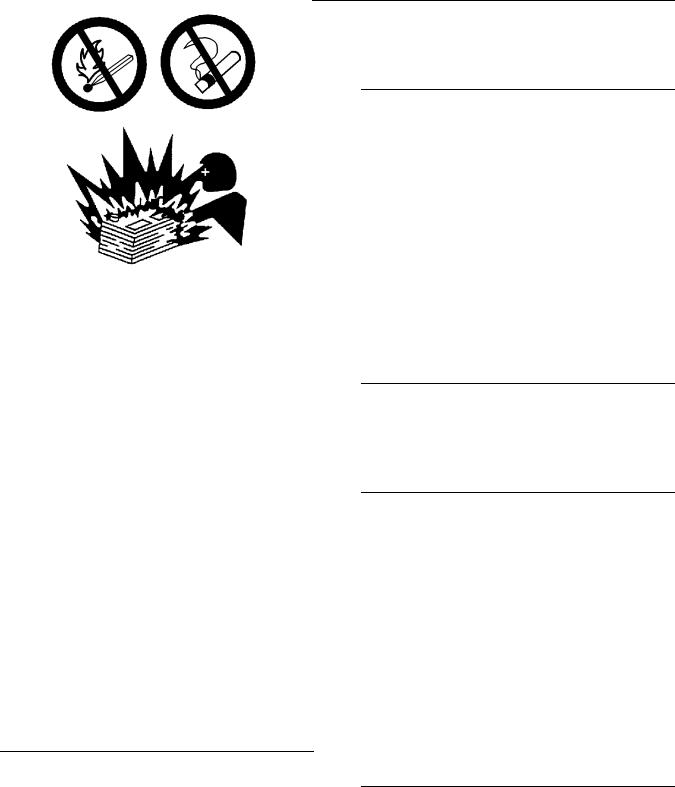
Illustration 7 |
g00704059 |
|
Use caution when you are refueling an engine. Do not smoke while you are refueling an engine. Do not refuel an engine near open flames or sparks. Always stop the engine before refueling.
Illustration 8 |
g00704135 |
|
Gases from a battery can explode. Keep any open flames or sparks away from the top of a battery. Do not smoke in battery charging areas.
Never check the battery charge by placing a metal object across the terminal posts. Use a voltmeter or a hydrometer.

SEBU8604 |
9 |
|
Safety Section |
|
Crushing Prevention and Cutting Prevention |
Incorrect jumper cable connections can cause an explosion that can result in injury. Refer to the Operation Section of this manual for specific instructions.
Do not charge a frozen battery. This may cause an explosion.
i02143194
Crushing Prevention and Cutting Prevention
The batteries must be kept clean. The covers (if equipped) must be kept on the cells. Use the
recommended cables, connections, and battery box covers when the engine is operated.
Fire Extinguisher
Make sure that a fire extinguisher is available. Be familiar with the operation of the fire extinguisher. Inspect the fire extinguisher and service the fire extinguisher regularly. Obey the recommendations on the instruction plate.
Support the component correctly when work beneath the component is performed.
Unless other maintenance instructions are provided, never attempt adjustments while the engine is running.
Stay clear of all rotating parts and of all moving parts. Leave the guards in place until maintenance is performed. After the maintenance is performed, reinstall the guards.
Keep objects away from moving fan blades. The fan blades will throw objects or cut objects.
Lines, Tubes and Hoses
Do not bend high pressure lines. Do not strike high pressure lines. Do not install any lines that are damaged.
Leaks can cause fires. Consult your Perkins dealer or your Perkins distributor for replacement parts.
Replace the parts if any of the following conditions are present:
•High pressure fuel line or lines are removed.
•End fittings are damaged or leaking.
•Outer coverings are chafed or cut.
•Wires are exposed.
•Outer coverings are ballooning.
•Flexible part of the hoses are kinked.
•Outer covers have embedded armoring.
•End fittings are displaced.
Make sure that all clamps, guards, and heat shields are installed correctly. During engine operation, this will help to prevent vibration, rubbing against other parts, and excessive heat.
When objects are struck, wear protective glasses in order to avoid injury to the eyes.
Chips or other debris may fly off objects when objects are struck. Before objects are struck, ensure that no one will be injured by flying debris.
i02235492
Mounting and Dismounting
Inspect the steps, the handholds, and the work area before mounting the engine. Keep these items clean and keep these items in good repair.
Mount the engine and dismount the engine only at locations that have steps and/or handholds. Do not climb on the engine, and do not jump off the engine.
Face the engine in order to mount the engine or dismount the engine. Maintain a three-point contact with the steps and handholds. Use two feet and one hand or use one foot and two hands. Do not use any controls as handholds.
Do not stand on components which cannot support your weight. Use an adequate ladder or use a work platform. Secure the climbing equipment so that the equipment will not move.
Do not carry tools or supplies when you mount the engine or when you dismount the engine. Use a hand line to raise and lower tools or supplies.

10 |
SEBU8604 |
Safety Section |
|
Before Starting Engine |
|
|
|
i02813489 |
All protective guards and all protective covers must |
Before Starting Engine |
be installed if the engine must be started in order |
to perform service procedures. To help prevent an |
|
|
accident that is caused by parts in rotation, work |
|
around the parts carefully. |
Before the initial start-up of an engine that is new, serviced or repaired, make provision to shut the engine off, in order to stop an overspeed. This may be accomplished by shutting off the air and/or fuel supply to the engine.
Overspeed shutdown should occur automatically for engines that are controlled electronically. If automatic shutdown does not occur, press the emergency stop button in order to cut the fuel and/or air to the engine.
Inspect the engine for potential hazards.
Before starting the engine, ensure that no one is on, underneath, or close to the engine. Ensure that the area is free of personnel.
If equipped, ensure that the lighting system for the engine is suitable for the conditions. Ensure that all lights work correctly, if equipped.
All protective guards and all protective covers must be installed if the engine must be started in order to perform service procedures. To help prevent an accident that is caused by parts in rotation, work around the parts carefully.
Always start the engine according to the procedure that is described in the Operation and Maintenance Manual, “Engine Starting” topic in the Operation Section. Knowing the correct procedure will help to prevent major damage to the engine components. Knowing the procedure will also help to prevent personal injury.
To ensure that the jacket water heater (if equipped) is working correctly, check the water temperature gauge (if equipped) and/or the oil temperature gauge (if equipped) during the heater operation.
Note: Do not use Lube oil heaters.
Engine exhaust contains products of combustion which can be harmful to your health. Always start the engine and operate the engine in a well ventilated area. If the engine is started in an enclosed area, vent the engine exhaust to the outside.
i02414676
Engine Stopping
Do not bypass the automatic shutoff circuits. Do not disable the automatic shutoff circuits. The circuits are provided in order to help prevent personal injury. The circuits are also provided in order to help prevent engine damage.
See the Service Manual for repairs and for adjustments.
i02414669
Engine Starting
Do not use aerosol types of starting aids such as ether. Such use could result in an explosion and personal injury.
If a warning tag is attached to the engine start switch or to the controls DO NOT start the engine or move the controls. Consult with the person that attached the warning tag before the engine is started.
Stop the engine according to the procedure in the Operation and Maintenance Manual, “Engine
Stopping” in order to avoid overheating of the engine and accelerated wear of the engine components.
Use the Emergency Stop Button ONLY in an emergency situation. Do not use the Emergency Stop Button for normal engine stopping. After an emergency stop, DO NOT start the engine until the problem that caused the emergency stop has been corrected.
Stop the engine if an overspeed condition occurs during the initial start-up of a new engine or an engine that has been overhauled. In the event of an overspeed condition, the air shutoff valves will operate. After operation, the air shutoff valves must be manually reset.
SEBU8604 |
11 |
|
Safety Section |
|
Electrical System |
|
|
i02414678 |
• Setpoint adjusters (if equipped) |
Electrical System
Never disconnect any charging unit circuit or battery circuit cable from the battery when the charging unit is operating. A spark can cause the combustible gases that are produced by some batteries to ignite.
To help prevent sparks from igniting combustible gases that are produced by some batteries, the negative “−” cable should be connected last from the external power source to the negative “−” terminal of the starting motor.
Check the electrical wires daily for wires that are loose or frayed. Tighten all loose electrical
connections before the engine is started. Repair all frayed electrical wires before the engine is started. See the Operation and Maintenance Manual for specific starting instructions.
Engines that are installed without engine-to-frame ground straps can be damaged by electrical discharge.
To ensure that the engine and the engine electrical systems function correctly, an engine-to-frame ground strap with a direct path to the battery must be used. This path may be provided by way of a direct engine ground to the frame.
The connections for the grounds should be tight and free of corrosion. The engine alternator must be grounded to the negative “-” battery terminal with
a wire that is adequate to handle the full charging current of the alternator.
•Sensors
•Wiring Harness
System Description
The system is controlled by an Electronic control Unit (ECU). The ECU contains a microprocessor that has an Electronic Programmable Read Only Memory (EPROM). The operating parameters for the governor are stored in the EPROM. The actuator is connected to the fuel injectors via a mechanical linkage.
A laptop computer is used to set the operating parameters of the governor. The laptop computer is connected to the governor via an interface cable. The operating parameters for the governor should only be modified by a trained Perkins representative. Refer to the Special Instruction, “Pandoras Digital Governor” for more information.
i02414684
Engine Electronics
Tampering with the electronic system installation or the OEM wiring installation can be dangerous and could result in personal injury or death and/or engine damage.
The engine is controlled by a digital Pandoras governor. The control system includes the following components.
•Control unit
•Actuator
12 |
SEBU8604 |
Product Information Section |
|
General Information |
|
Product Information
Section
General Information
i02640420
Welding on Engines with Electronic Controls
NOTICE
Proper welding procedures are necessary in order to avoid damage to the engine's ECM, sensors, and associated components. When possible, remove the component from the unit and then weld the component. If removal of the component is not possible, the following procedure must be followed when you weld with a unit that is equipped with an Electronic Engine. The following procedure is considered to be the safest procedure to weld a component. This procedure should provide a minimum risk of damage to electronic components.
NOTICE
Do not ground the welder to electrical components such as the ECM or sensors. Improper grounding can cause damage to the drive train bearings, hydraulic components, electrical components, and other components.
Clamp the ground cable from the welder to the component that will be welded. Place the clamp as close as possible to the weld. This will help reduce the possibility of damage.
1.Stop the engine. Turn the switched power to the OFF position.
2.Disconnect the negative battery cable from the battery. If a battery disconnect switch is provided, open the switch.
3.Disconnect the connectors from the ECM.
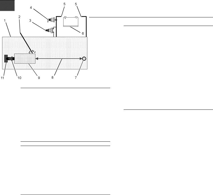
Illustration 9 |
g01324562 |
|
Use the example above. The current flow from the welder to the ground clamp of the welder will not cause damage to any associated components.
(1)Engine
(2)Welding rod
(3)Keyswitch in the OFF position
(4)Battery disconnect switch in the open position
(5)Disconnected battery cables
(6)Battery
(7)Electrical/Electronic component
(8)Maximum distance between the component that is being welded and any electrical/electronic component
(9)The component that is being welded
(10)Current path of the welder
(11)Ground clamp for the welder
4.Connect the welding ground cable directly to the part that will be welded. Place the ground cable as close as possible to the weld in order to reduce the possibility of welding current damage to bearings, hydraulic components, electrical components, and ground straps.
Note: If electrical/electronic components are used as a ground for the welder, or electrical/electronic components are located between the welder ground and the weld, current flow from the welder could severely damage the component.
5.Protect the wiring harness from welding debris and spatter.
6.Use standard welding practices to weld the materials.

SEBU8604 |
13 |
|
Product Information Section |
|
Model Views |
Model Views
i03754000
Model View Illustrations
4016-61TRG
The following model views show typical features of the engine. Due to individual applications, engines may appear different from the Illustrations.
Note: Only serviced components are identified on the following Illustrations.

14 |
SEBU8604 |
Product Information Section |
|
Model Views |
|
|
|
|
|
Illustration 10 |
|
g02029553 |
|
|
|
||
Left side view of engine |
|
|
|
(1) Engine crankcase breather (A Bank) |
(5) Engine crankcase breather (B Bank) |
(9) Oil level gauge (Dipstick) |
|
(2) |
Thermostat housing (A Bank) |
(6) Air shutoff valve (B Bank) |
(10) Oil filler |
(3) |
Electronic governor actuator |
(7) 3x Oil filters (B Bank) |
(11) Water pump |
(4) |
Thermostat housing (B Bank) |
(8) Oil cooler |
(12) Stop solenoid |
SEBU8604 |
15 |
|
Product Information Section |
|
Model Views |
|
|
|
|
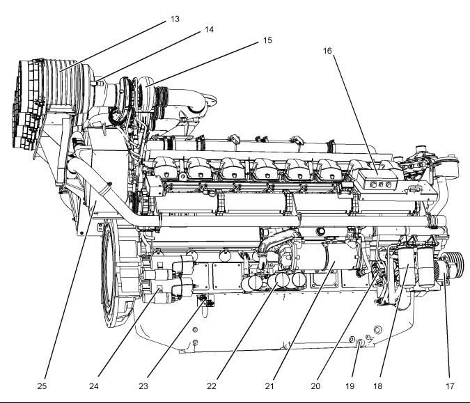
Illustration 11 |
|
|
|
Right side view of engine |
|
|
|
(13) |
Air cleaner |
(18) |
Fuel filters |
(14) |
Restriction indicator for air cleaner |
(19) |
Oil drain plug |
(15) |
Turbocharger |
(20) |
Fuel priming pump |
(16) |
Electronic governor control unit |
(21) |
Oil cooler (A Bank) |
(17) |
Alternator |
(22) 3x Oil filters (A Bank) |
|
|
|
|
i03754029 |
Engine Description
The 4016-61 TRG engine model is designed for power generation. The engine is available with turbocharged aftercooled aspiration.
g02029554
(23)Starter relay
(24)Starting motor
(25)Aftercooler
Engine Specifications
Note: The number 1 cylinders are to the front. The front of the engine is farthest from the flywheel. Bank A cylinders are on the right hand side of the engine. Bank B cylinders are on the left hand side of the engine. To determine the left and right sides of the engine, stand behind the flywheel and face the dampers.
16 |
SEBU8604 |
Product Information Section |
|
Model Views |
|
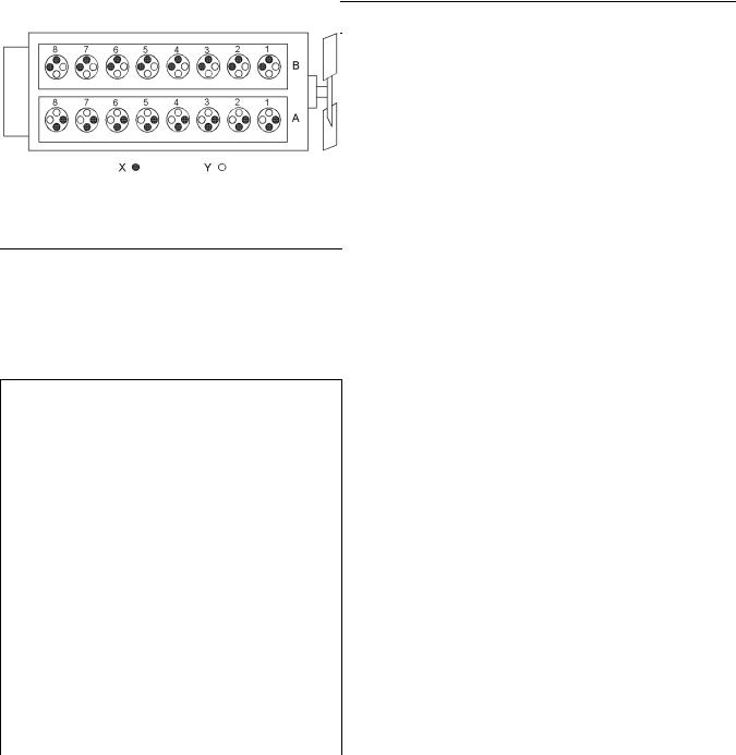
Illustration 12 |
g01210841 |
|
|
4016-61 TRG engine model |
|
(A)Bank
(B)Bank
(X)Inlet valves
(Y)Exhaust valves
Table 1
4016-61 Engine Specifications
Cycle |
4 Stroke |
|
|
|
|
Number of |
16 |
|
Cylinders |
||
|
||
Configuration |
Vee-form |
|
|
|
|
Bore |
160 mm (6.299 inch) |
|
|
|
|
Stroke |
190 mm (7.480 inch) |
|
|
|
|
Displacement |
61.123 L (3729.954 in3) |
|
Compression |
13:1 |
|
Ratio |
||
|
||
Rotation |
Counterclockwise |
|
(flywheel end) |
||
|
||
Firing Order |
1A-1B-3A-3B-7A-7B-5A-5B-8A-8B- |
|
6A-6B-2A-2B-4A-4B |
||
|
||
|
|
|
Inlet Valve Lash |
0.40 mm (0.016 inch) |
|
(Cold) |
||
|
||
Exhaust Valve |
0.40 mm (0.016 inch) |
|
Lash (Cold) |
||
|
Engine Cooling and Lubrication
The cooling system consists of the following components:
•Gear-driven water pumps
•Water temperature regulators which regulate the engine coolant temperature
•Gear-driven oil pump (gear type)
•Oil coolers
The engine lubricating oil is supplied by a gear-driven pump. The lubrication oil is cooled and filtered. Bypass valves provide unrestricted flow of lubrication oil to the engine parts when oil viscosity is high. Bypass valves can also provide unrestricted flow
of lubrication oil to the engine parts if the oil filter element should become plugged.
Engine efficiency, efficiency of emission controls, and engine performance depend on adherence to proper operation and maintenance recommendations.
Engine performance and efficiency also depend on the use of recommended fuels, lubrication oils, and coolants. Refer to this Operation and Maintenance Manual, “Maintenance Interval Schedule” for more information on maintenance items.

SEBU8604 |
17 |
|
Product Information Section |
|
Product Identification Information |
Product Identification
Information
i03754088
Plate Locations and Film Locations
Engine Identification
Perkins engines are identified by an engine serial number.
A typical example of an engine serial number is DGB R**** U00001M.
D _________________________________________Made in Stafford G ____________________________________Application (Table 2) B ________________________________Type of engine (Table 3)
R _________________________Number of cylinders(Table 4)
***** __________________________________Fixed build number U ____________________________Built in the United Kingdom 00001 ____________________________________Engine Number M ____________________________________Year of Manufacture
Table 2
Application
G Genset
I Gas
Table 3
|
|
Type of engine (Diesel) |
|
|
|
F |
|
TG |
|
|
|
L |
|
TAG |
|
|
|
A |
|
TAG1 |
|
|
|
B |
|
TAG2 |
|
|
|
D |
|
TAG3 |
|
|
|
M |
|
TWG |
|
|
|
K |
|
TWG2 |
|
|
|
N |
|
TWG3 |
|
|
|
P |
|
TRG1 |
|
|
|
R |
|
TEG2 |
|
|
|
S |
|
TEG3 |
|
|
|
W |
|
TRG2 |
|
|
|
X |
|
TGR3 |
|
|
|
|
|
Type of engine (Gas) |
|
|
|
F |
|
TESI Gas unit |
|
|
|
E |
|
TESI Combined Heat and Power unit |
|
|
|
G |
|
4016-E61-TRS |
|
|
|
H |
|
TRS Combined Heat and Power Unit |
|
|
|
J |
|
TRS Gas Unit |
|
|
|
Table 4 |
|
|
|
|
|
|
|
Number of Cylinders |
|
|
|
F |
6 |
|
|
|
|
H |
8 |
|
|
|
|
M |
12 |
|
|
|
|
R |
16 |
|
|
|
|
Perkins dealers and Perkins distributors require all of these numbers in order to determine the components that were included in the engine. This permits accurate identification of replacement part numbers.
18 |
SEBU8604 |
Product Information Section |
|
Product Identification Information |
|
Serial Number Plate
Illustration 13 |
g01266904 |
|
|
Serial number plate |
|
The engine serial number plate contains the following information:
•Place of manufacture
•Telephone number of manufacturer
•Fax number of manufacturer
•Type of engine
•Engine serial number
•Rated speed
•Power output
•Engine timing
•Rating
Illustration 14 |
g02029586 |
|
|
Typical example |
|
The serial number plate (1) on a engine is located on the left side of the cylinder block (bank B).
SEBU8604
Operation Section
Lifting and Storage
i03880885
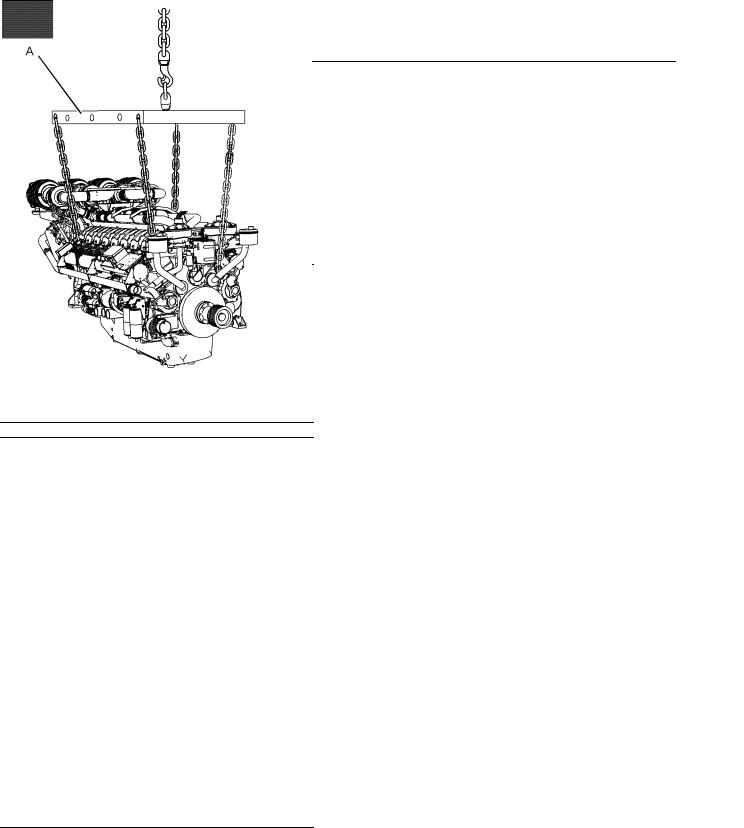
Engine Lifting
NOTICE
Never bend the eyebolts and the brackets. Only load the eyebolts and the brackets under tension. Remember that the capacity of an eyebolt is less as the angle between the supporting members and the object becomes less than 90 degrees.
When it is necessary to remove a component at an angle, only use a link bracket that is properly rated for the weight.
Illustration 15 |
g02126835 |
|
|
Typical example |
|
Use a hoist to remove heavy components. Use a lifting beam (A) to lift the engine. All supporting members (chains and cables) should be parallel to each other. The chains and cables should be perpendicular to the top of the object that is being lifted.
19 Operation Section Lifting and Storage
20 |
SEBU8604 |
Operation Section |
|
Lifting and Storage |
|
|
|
|
|
Illustration 16 |
|
(1) Front lifting eyes |
(2) Rear lifting eye |
To remove the engine ONLY, use the lifting eyes that are shown in illustration 16. If necessary, remove engine components in order to avoid damage from the lifting device.
g02131153
Lifting eyes are designed and installed for specific engine arrangements. Alterations to the lifting eyes and/or the engine make the lifting eyes and the lifting fixtures obsolete. If alterations are made, ensure that correct lifting devices are provided. Consult your Perkins dealer or your Perkins distributor for information regarding fixtures for correct engine lifting.
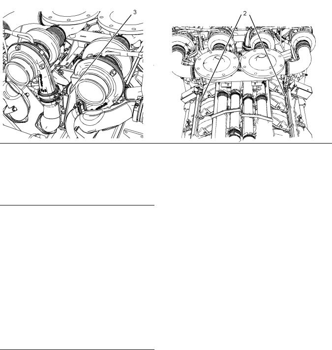
Illustration 17 |
g02130795 |
|
Note: The lifting eye (3) must NOT be used in order to lift the engine. The lifting eye (3) has not been designed in order to lift the engine. The lifting eye is used in factory assembly of engine components.
SEBU8604
i03781209
Engine Storage
Refer to Perkins Engine Company Limited, Stafford, ST16 3UB for information on engine storage.
There are three different levels of engine storage. Level “A, B and C”.
Level “A ”
Level “A” will give protection for 12 months for diesel engines and for gas engines. This level is used for engines that are transported in a container or by a truck.
Level “B ”
This level is additional to level “A”. Level “B ” will give protection under normal conditions of storage from −15° to +55°C (5° to 99°F) and “90%” relative humidity, for a maximum of 2 year.
Level “C ”
This level is additional to level “B”. Level “C” will give protection for five years in tropical or in arctic climates. Level “C” also meets MOD NES 724 Level “J” for Europe, when engines are stored in an unheated building or in the open under a waterproof cover.
21 Operation Section Lifting and Storage
22 |
SEBU8604 |
Operation Section |
|
Features and Controls |
|
Features and Controls
i03882309
Monitoring System
The engine is equipped with sensors or switches to monitor the following parameters:
•Coolant temperature (Switch)
•Oil pressure (Switch)
•Intake manifold boost pressure (Sensor)
•Exhaust temperature Sensors
•Engine speed (Sensor)
•Engine overspeed (Sensor or Switch)
i03781211
Sensors and Electrical Components
Sensor Locations
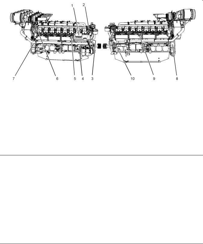
Illustration 18 |
|
|
g02088773 |
|
|
|
|
||
(1) |
Electronic control unit (ECU) |
(5) High turbine inlet temperature shutdown |
(8) Overspeed sensor |
|
(2) |
Coolant temperature sensor |
|
sensor (A bank) |
(9) High turbine inlet temperature shutdown |
(3) |
Boost pressure sensor |
(6) |
Thermocouple |
sensor (B bank) |
(4) Oil pressure switch |
(7) |
Speed sensor |
(10) Oil pressure switch |
|
SEBU8604 |
23 |
|
Operation Section |
|
Features and Controls |
The Illustrations show the typical locations of the sensors on the engine. Specific engines may appear different from the illustrations due to differences in applications.
Coolant Temperature Sensor
The boost pressure sensor (3) measures the pressure in the inlet air manifold. A signal is sent to the ECU (1).
Illustration 19 |
g02088775 |
|
|
Coolant temperature switches |
|
The coolant temperature switches (2) monitor the engine coolant temperature. The switches are supplied for connecting to an OEM supplied panel.
Boost Pressure Sensors
Illustration 20 |
g02125658 |
|
|
Boost pressure sensor |
|
24 |
SEBU8604 |
Operation Section |
|
Features and Controls |
|
Engine Oil Pressure Switch
Illustration 21 |
g02041294 |
|
|
Engine oil pressure sensor |
|
(4) Oil pressure sensor (A Bank) |
(9) Oil pressure sensor (B Bank) |
An oil pressure sensor is installed on both side of the engine. The engine oil pressure sensors are mounted in the main oil gallery. The engine oil pressure sensors are supplied for connecting to an OEM supplied panel.
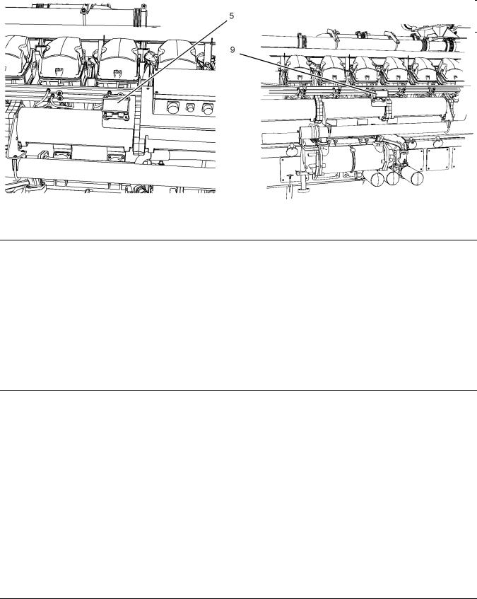
High Turbine Inlet Temperature
Shutdown Sensor
Illustration 22
(5)High turbine inlet temperature shutdown sensor (A bank)
g02124274
(8)High turbine inlet temperature shutdown sensor (B bank)

SEBU8604 |
25 |
|
Operation Section |
|
Features and Controls |
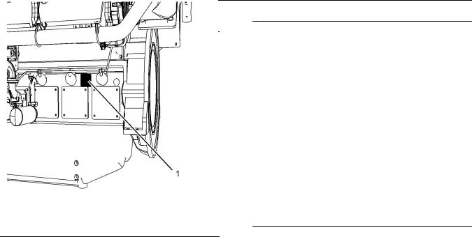
Illustration 23 |
g02123434 |
|
|
Thermocouple |
|
Four thermocouples are installed. One thermocouple is installed in each of the exhaust manifolds. There are two high turbine inlet temperature shutdown sensors. One sensor monitors each engine bank.
A sensor monitors two thermocouples. If high temperatures are indicated the engine will be shutdown.
Speed Sensor
The speed sensor (7) should be serviced at the required maintenance interval. Refer to the
Operation and Maintenance Manual, “Speed Sensor, Clean/Inspect”.
Failure of the Speed Sensor
If the ECU (1) does not receive a signal from the speed sensor (4), the engine cannot run.
If the ECU does not receive a signal from the speed sensor (7), the engine will shut down. A faulty speed sensor should be replaced.
Note: Intermittent failure of the speed sensor will cause the engine to run erratically. This may also cause overspeed.
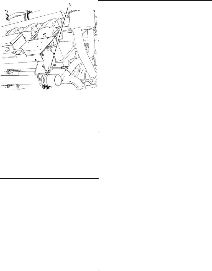
Overspeed Sensor
Illustration 25 |
g01231518 |
|
|
Overspeed sensor |
|
The signal from the overspeed sensor (8) is connected to the overspeed switch or the overspeed circuit in the OEM supplied panel.
The location of the sensor can vary depending on the application.
Illustration 24 |
g02123433 |
|
|
Speed sensor |
|
 Loading...