


1U7
PANJIT 1U7, 1U6, 1U5, 1U4, 1U3 Datasheet
...
1U1 THRU 1U7
FEATURE
S
MECHANICAL DATA
MAXIMUM RATINGS AND ELECTRICAL CHARACTERISTIC
S
1U61U
7
R
M
F
M
P
1.
2.
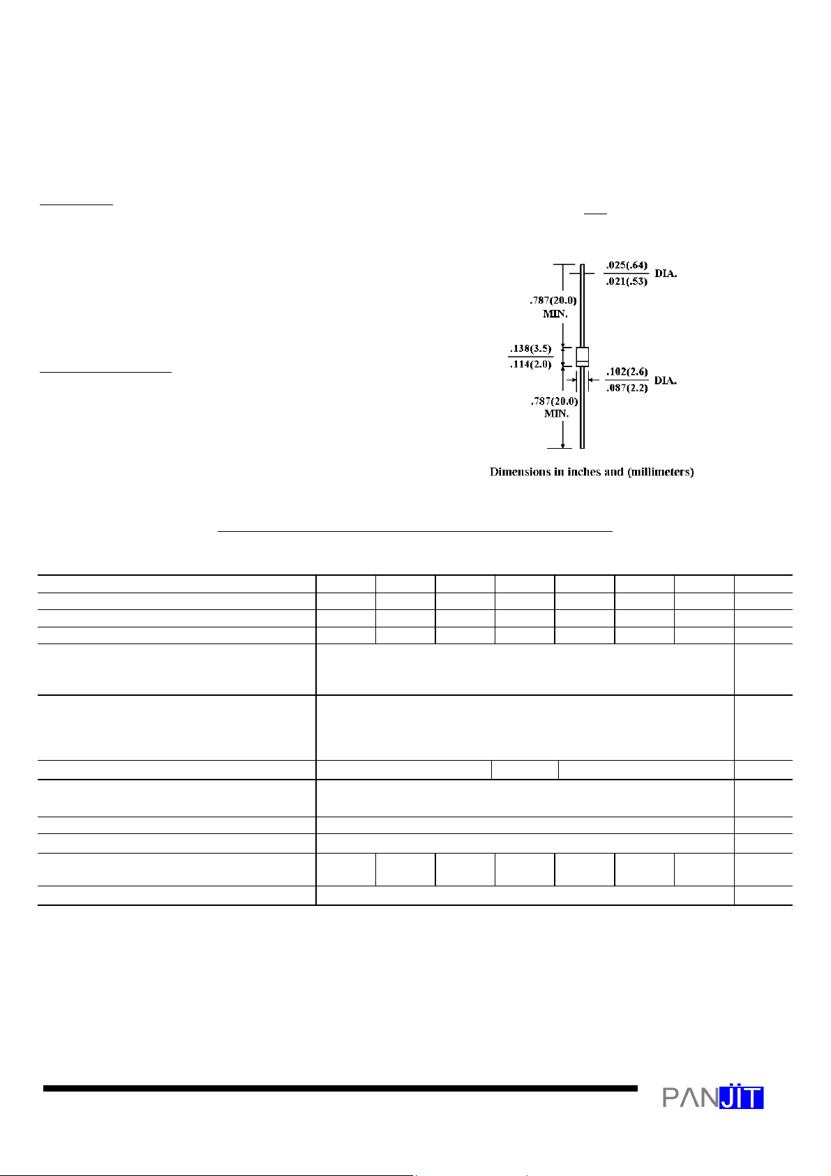
R-1
ULTRAFA ST SWITCHING RECTIFIER
VOLTAGE - 50 to 1000 Volts CURRENT - 1.0 A mpere
l
Plastic package has Underwriters Laboratory
Flammability Classification 94V-O utilizing
Flame Retardant Epoxy Molding Compound
l
1 ampere operation at TA=55¢Jwith no thermal runaway
l
Exceeds environmental standards of MIL-S-19500/228
l
Ultra fast switching for high efficiency
Case: Molded plastic, R-1
Terminals: Axial leads, solderable per MIL-STD-202,
Method 208
Polarity: Band denotes cathode
Mounting Position: Any
Weight: 0.0064 ounce, 0.181 gram
Ratings at 25¢J ambient temperature unless otherwise specified.
Single phase, half wave, 60 Hz, resistive or inductive load.
Peak Reverse Voltage, Pepetitive ; V
1U1 1U2 1U3 1U4 1U5
50 100 200 400 600 800 1000 V
UNITS
Maximum RMS Voltage 35 70 140 280 420 560 700 V
DC Blocking Voltage; VR 50 100 200 400 600 800 1000 V
Average Forward Rectified, Io @TA=55 ¢J
1.0 A
3/8” lead length, 60Hz, resistive or inductive
load
Peak Forward Surge Current I
(surge)
30.0 A
8.3msec. single half sine-wave
superimposed on rated load (JEDEC
method)
Maximum Forward Voltage VF @1.0A, 25
Maximum Reverse Current, @ Rated TJ=25
Reverse Voltage TJ=100 ¢J
Typical Junction capacitance (Note 1) CJ 17
¢J 1.00 1.10 1.70 V
¢J
10.0
500
£g
£g A
A
F
Typical Thermal Resistance (Note 2) R£KJA 65.0 ¢J/W
Maximum Reverse Recovery Time
50 50 50 50 75 75 75 ns
IF=.5A, IR=1A, Irr=.25A
Operating and Storage T emperature Range -55 TO +150 ¢J
NOTES:
Measured at 1 MHz and applied reverse voltage of 4.0 VDC
Thermal resistance from junction to ambient and from junction to lead length 0.375”(9.5mm) P.C.B. mounted
 Loading...