


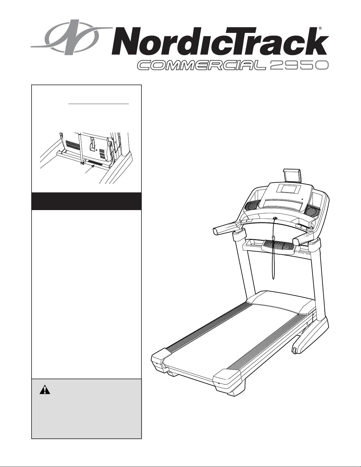
Model No. NETL29716.0
Serial No.
Write the serial number in the space
above for reference.
Serial Number
Decal
CUSTOMER SERVICE
UNITED KINGDOM
Call: 0330 123 1045
From Ireland: 053 92 36102
Website: www.iconsupport.eu
E-mail: csuk@iconeurope.com
Write:
ICON Health & Fitness, Ltd.
Unit 1D, The Gateway
Fryers Way, Silkwood Park
OSSETT
WF5 9TJ
UNITED KINGDOM
USER’S MANUAL
AUSTRALIA
Call: 1800 993 770
E-mail: australiacc@iconfitness.com
Write:
ICON Health & Fitness
PO Box 635
WINSTON HILLS NSW 2153
AUSTRALIA
CAUTION
Read all precautions and instructions in this manual before using
this equipment. Save this manual
for future reference.
www.iconeurope.com
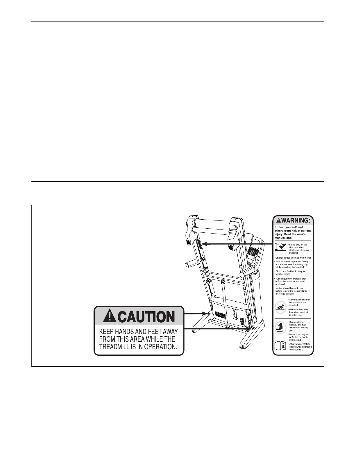
TABLE OF CONTENTS
WARNING DECAL PLACEMENT . . . . . . . . . . . . . . . . . . . . . . . . . . . . . . . . . . . . . . . . . . . . . . . . . . . . . . . . . . . . . . .2
IMPORTANT PRECAUTIONS ..................................................................3
BEFORE YOU BEGIN. . . . . . . . . . . . . . . . . . . . . . . . . . . . . . . . . . . . . . . . . . . . . . . . . . . . . . . . . . . . . . . . . . . . . . . .5
PART IDENTIFICATION CHART. . . . . . . . . . . . . . . . . . . . . . . . . . . . . . . . . . . . . . . . . . . . . . . . . . . . . . . . . . . . . . . .6
ASSEMBLY . . . . . . . . . . . . . . . . . . . . . . . . . . . . . . . . . . . . . . . . . . . . . . . . . . . . . . . . . . . . . . . . . . . . . . . . . . . . . . . .7
THE CHEST HEART RATE MONITOR. . . . . . . . . . . . . . . . . . . . . . . . . . . . . . . . . . . . . . . . . . . . . . . . . . . . . . . . . .15
HOW TO USE THE TREADMILL ..............................................................16
HOW TO UPGRADE THE CONSOLE ..........................................................17
HOW TO FOLD AND MOVE THE TREADMILL ...................................................31
MAINTENANCE AND TROUBLESHOOTING .....................................................32
EXERCISE GUIDELINES ....................................................................35
PART LIST. . . . . . . . . . . . . . . . . . . . . . . . . . . . . . . . . . . . . . . . . . . . . . . . . . . . . . . . . . . . . . . . . . . . . . . . . . . . . . . .38
EXPLODED DRAWING. . . . . . . . . . . . . . . . . . . . . . . . . . . . . . . . . . . . . . . . . . . . . . . . . . . . . . . . . . . . . . . . . . . . . .40
ORDERING REPLACEMENT PARTS. . . . . . . . . . . . . . . . . . . . . . . . . . . . . . . . . . . . . . . . . . . . . . . . . . . Back Cover
RECYCLING INFORMATION ......................................................... Back Cover
WARNING DECAL PLACEMENT
This drawing shows the locations of the warning
decals. If a decal is missing or illegible, call
the telephone number on the front cover of
this manual and request a free replacement
decal. Apply the decal in the location shown.
Note: The decals may not be shown at actual size.
The BLUETOOTH® word mark and logos are registered trademarks of Bluetooth SIG, Inc.
and are used under license. Google Maps is a trademark of Google Inc.
NORDICTRACK is a registered trademark of ICON Health & Fitness, Inc.
2

IMPORTANT PRECAUTIONS
WARNING: To reduce the risk of burns, fire, electric shock, or injury to persons, read
all important precautions and instructions in this manual and all warnings on your treadmill before
using your treadmill. ICON assumes no responsibility for personal injury or property damage sustained by or through the use of this product.
1. It is the responsibility of the owner to ensure
that all users of this treadmill are adequately
informed of all warnings and precautions.
2. Before beginning any exercise program,
consult your physician. This is especially
important for persons over age 35 or persons
with pre-existing health problems.
3. The treadmill is not intended for use by
persons with reduced physical, sensory, or
mental capabilities or lack of experience and
knowledge, unless they have been given
supervision or instruction concerning use
of the treadmill by someone responsible for
their safety.
4. Use the treadmill only as described in this
manual.
5. Keep the treadmill indoors, away from moisture and dust. Do not put the treadmill in a
garage or covered patio, or near water.
6. Place the treadmill on a level surface, with
at least 8 ft. (2.4 m) of clearance behind it
and 2 ft. (0.6 m) on each side. Do not place
the treadmill on any surface that blocks air
openings. To protect the floor or carpet from
damage, place a mat under the treadmill.
11. Wear appropriate exercise clothes while
using the treadmill. Do not wear loose
clothes that could become caught in the
treadmill. Athletic support clothes are recommended for both men and women. Always
wear athletic shoes. Never use the treadmill
with bare feet, wearing only stockings, or in
sandals.
12. When connecting the power cord (see page
16), plug the power cord into an earthed
circuit. No other appliance should be on the
same circuit. When replacing the fuse in the
power cord adapter, insert an ASTA-approved
BS1362, 13-amp fuse into the fuse carrier.
13. If an extension cord is needed, use only a
3-conductor, 14-gauge (1 mm2) cord that is
no longer than 5 ft. (1.5 m).
14. Keep the power cord away from heated
surfaces.
15. Never move the walking belt while the power
is turned off. Do not operate the treadmill
if the power cord or plug is damaged, or if
the treadmill is not working properly. (See
MAINTENANCE AND TROUBLESHOOTING
on page 32 if the treadmill is not working
properly.)
7. Do not operate the treadmill where aerosol
products are used or where oxygen is being
administered.
8. Keep children under age 13 and pets away
from the treadmill at all times.
9. The treadmill should be used only by persons weighing 297 lbs. (135 kg) or less.
10. Never allow more than one person on the
treadmill at a time.
16. Read, understand, and test the emergency
stop procedure before using the treadmill
(see HOW TO TURN ON THE POWER on
page 19). Always wear the clip while using the
treadmill.
17. Always stand on the foot rails when starting
or stopping the walking belt. Always hold the
handrails while using the treadmill.
18. When a person is walking on the treadmill,
the noise level of the treadmill will increase.
3

19. Keep fingers, hair, and clothing away from
the moving walking belt.
20. The treadmill is capable of high speeds.
Adjust the speed in small increments to
avoid sudden jumps in speed.
24. When folding or moving the treadmill, make
sure that the storage latch is holding the
frame securely in the storage position.
25. Do not change the incline of the treadmill by
placing objects under the treadmill.
21. The heart rate monitor is not a medical
device. Various factors, including the user’s
movement, may affect the accuracy of heart
rate readings. The heart rate monitor is
intended only as an exercise aid in determining heart rate trends in general.
22. Never leave the treadmill unattended while
it is running. Always remove the key, press
the power switch into the off position (see
the drawing on page 5 for the location of the
power switch), and unplug the power cord
when the treadmill is not in use.
23. Do not attempt to move the treadmill until
it is properly assembled. (See ASSEMBLY
on page 7 and HOW TO FOLD AND MOVE
THE TREADMILL on page 31.) You must be
able to safely lift 45 lbs. (20 kg) to move the
treadmill.
SAVE THESE INSTRUCTIONS
26. Never insert any object into any opening on
the treadmill.
27. Inspect and properly tighten all parts each
time the treadmill is used.
28. DANGER: Always unplug the power
cord immediately after use, before cleaning the treadmill, and before performing the
maintenance and adjustment procedures
described in this manual. Never remove the
motor hood unless instructed to do so by an
authorized service representative. Servicing
other than the procedures in this manual
should be performed by an authorized service representative only.
29. Over exercising may result in serious injury
or death. If you feel faint, if you become short
of breath, or if you experience pain while
exercising, stop immediately and cool down.
4
BEFORE YOU BEGIN
Thank you for selecting the revolutionary
NORDICTRACK® COMMERCIAL 2950 treadmill. The
COMMERCIAL 2950 treadmill offers an impressive
selection of features designed to make your work-
outs more effective and enjoyable. And when you’re
not exercising, the unique treadmill can be folded
up, requiring less than half the floor space of other
treadmills.
For your benefit, read this manual carefully before
using the treadmill. If you have questions after
Length: 6 ft. (183 cm)
Width: 2 ft. 10 in. (86 cm)
Weight: 280 lbs (127 kg)
Heart Rate Monitor
Handrail
reading this manual, please see the front cover of this
manual. To help us assist you, please note the product
model number and serial number before contacting us.
The model number and the location of the serial number decal are shown on the front cover of this manual.
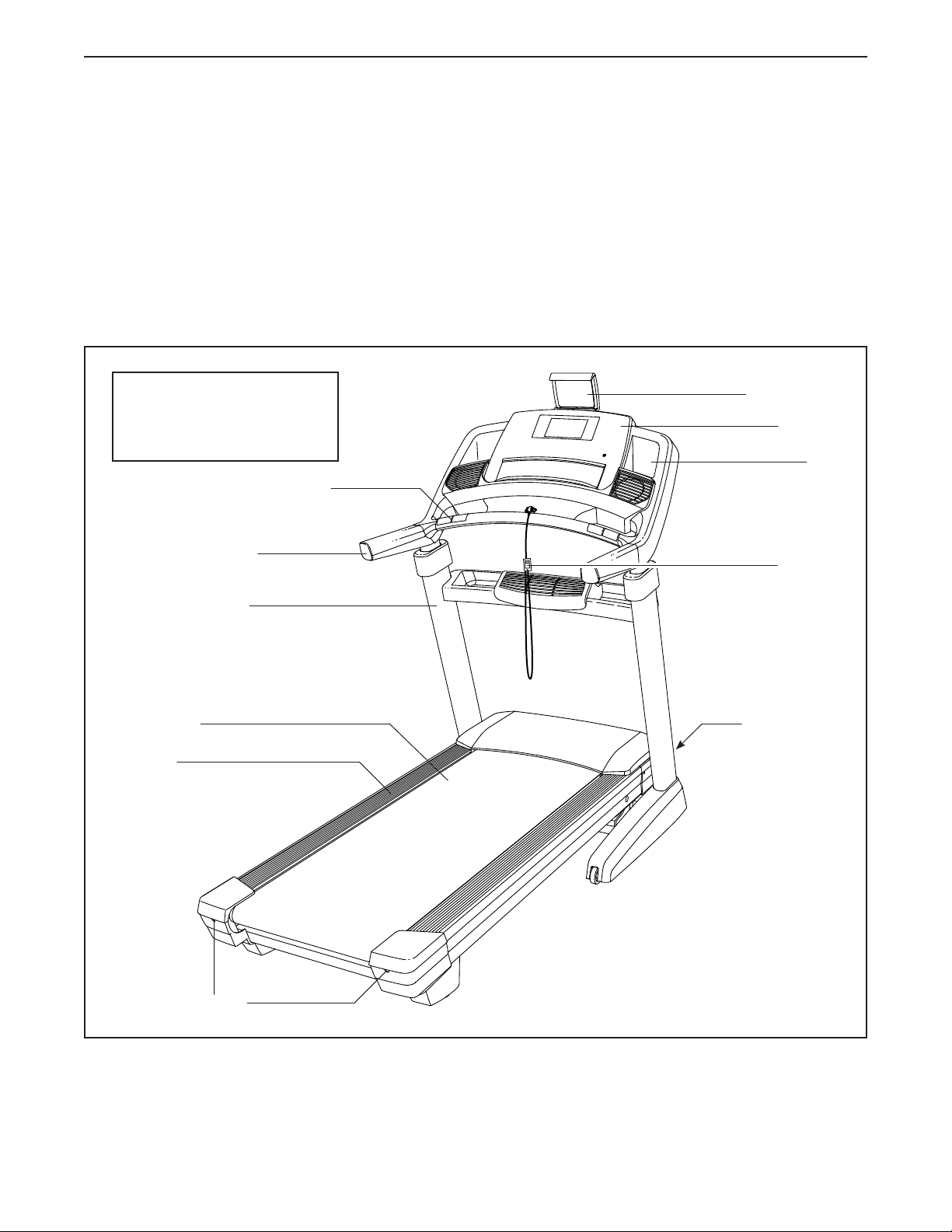
Before reading further, please review the drawing
below and familiarize yourself with the labeled parts.
Tablet Holder
Console
Tray
Key/Clip
Upright
Walking Belt
Foot Rail
Idler Roller
Adjustment Screws
Power Switch
5
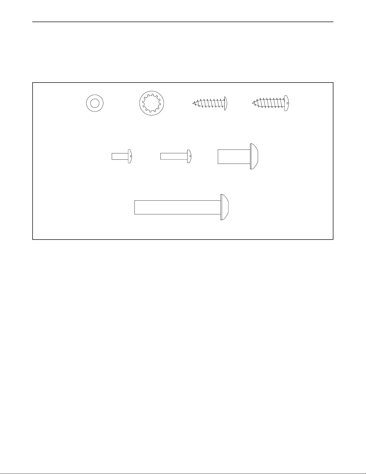
PART IDENTIFICATION CHART
Use the drawings below to identify small parts used for assembly. The number in parentheses below each drawing is the key number of the part, from the PART LIST near the end of this manual. The number following the key
number is the quantity used for assembly. Note: If a part is not in the hardware kit, check to see whether it is
preattached. Extra parts may be included.
#8 Flat Washer
(23)–4
#8 x 3/8"
Machine
5/16" Star Washer
Screw
(142)–4
(8)–4
#8 x 5/8"
Machine
(108)–4
5/16" x 2" Screw (2)–4
Truss Head Screw
Screw
#8 x 3/4"
(24)–16
5/16" x 3/4" Screw
(1)–4
#10 x 3/4"
Screw
(6)–2
6
ASSEMBLY
• Assembly requires two persons.
• Place all parts in a cleared area and remove the
packing materials. Do not dispose of the packing
materials until you nish all assembly steps.
• After shipping, there may be an oily substance
on the exterior of the treadmill. This is normal. If
there is an oily substance on the treadmill, wipe
it off with a soft cloth and a mild, non-abrasive
cleaner.
• Left parts are marked “L” or “Left” and right parts
are marked “R” or “Right.”
1. Go to www.iconsupport.eu on your computer
and register your product.
• activates your warranty
• saves you time if you ever need to contact
Customer Service
• allows us to notify you of upgrades and offers
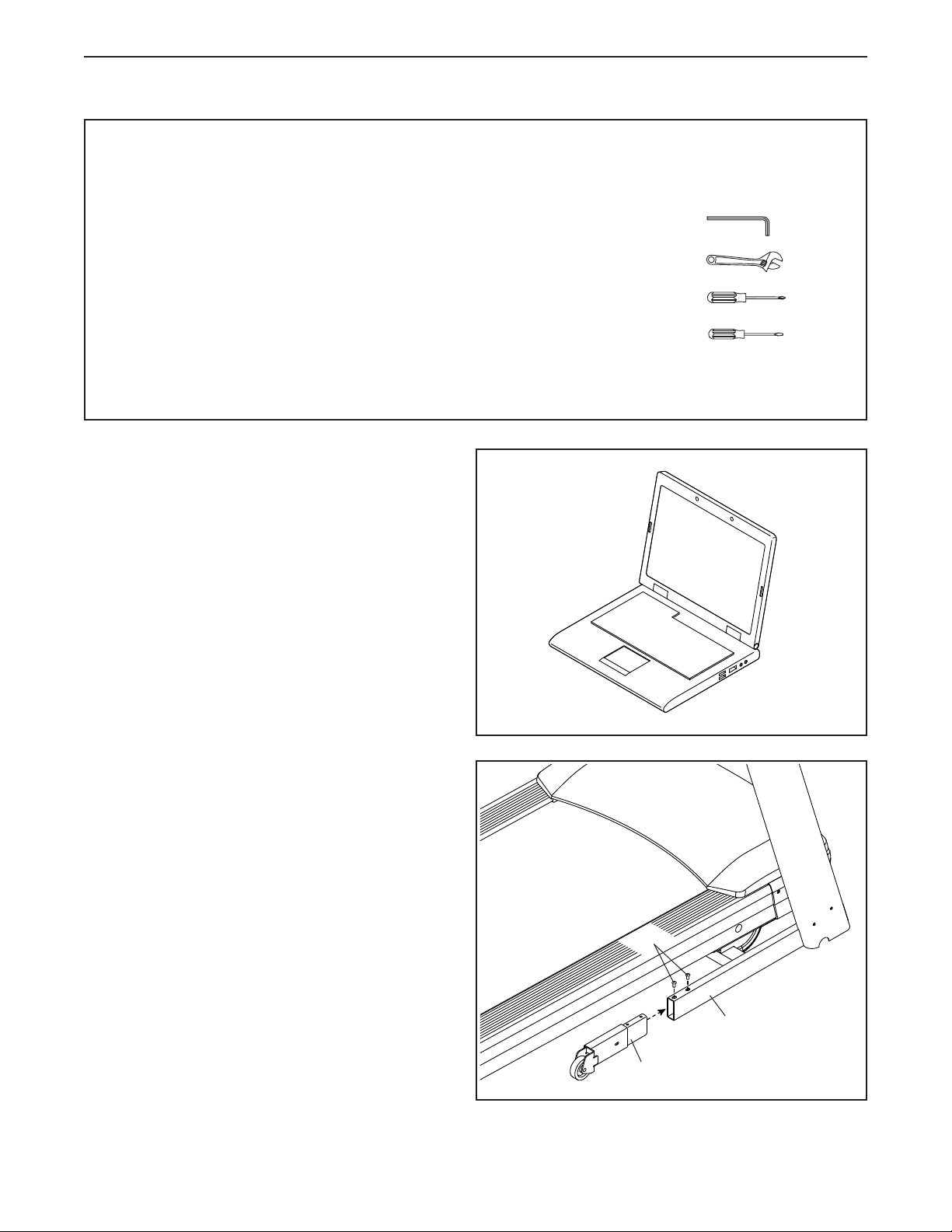
• To identify small parts, see page 6.
• Assembly requires the following tools:
the included hex key
one adjustable wrench
one Phillips screwdriver
one standard screwdriver
To avoid damaging parts, do not use power tools.
1
Note: If you do not have internet access, call
Customer Service (see the front cover of this
manual) and register your product.
2. Make sure that the power cord is unplugged.
Identify the Right Extension Leg (91). Attach the
Right Extension Leg to the right Upright (84) with
two 5/16" x 3/4" Screws (1); start both Screws,
and then tighten them.
Attach the Left Extension Leg (not shown) to
the left Upright (not shown) in the same way.
2
1
84
91
7
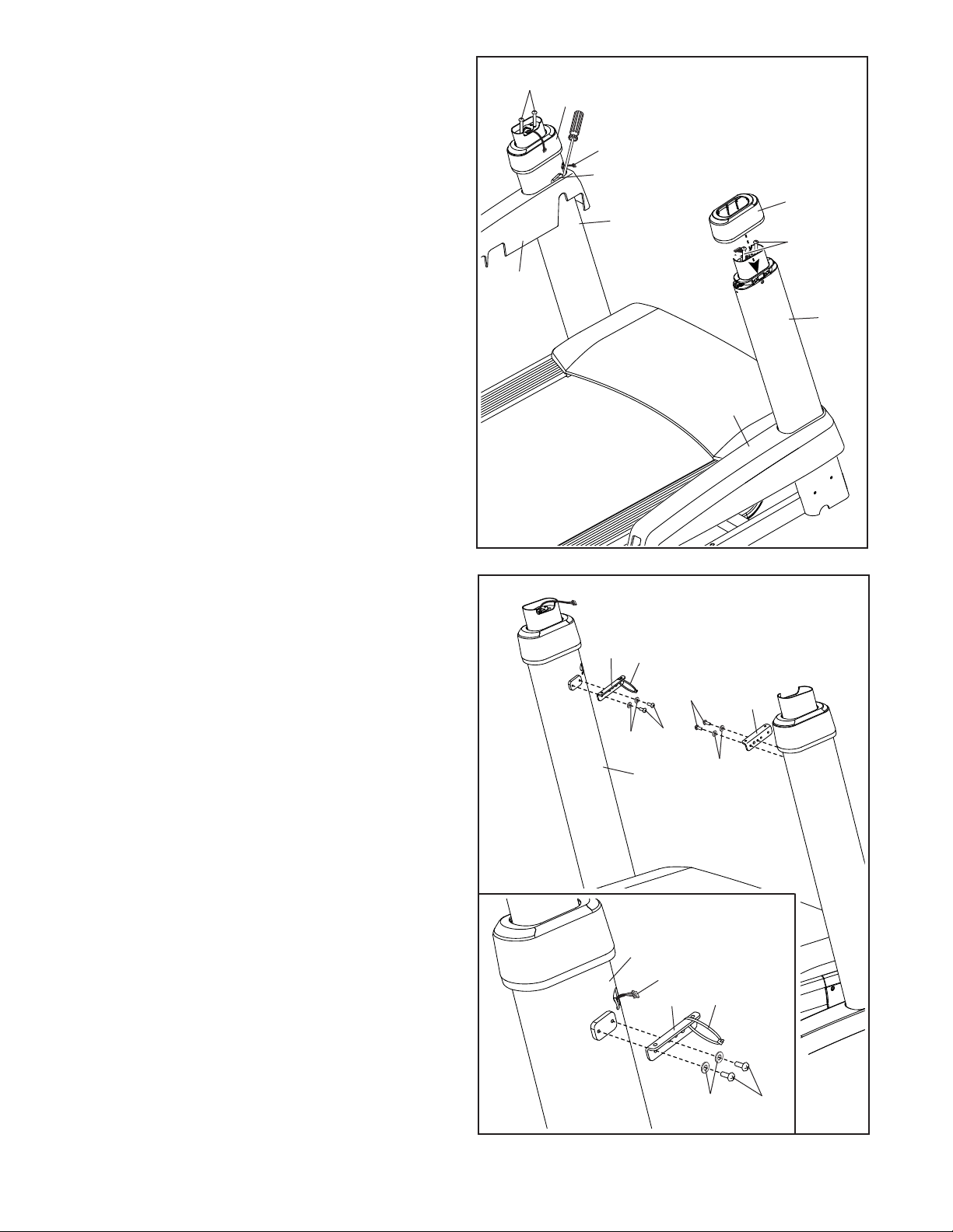
3. Insert the fan wire (A) into the left Upright (84).
Next, slide the Left Base Cover (89) onto the
left Upright (84), and slide the Right Base Cover
(90) onto the right Upright. Tip: You may need
to use a standard screwdriver to pull the Left
Base Cover away from the left Upright so that
the Left Base Cover will slide over the welded
plate (B). Next, press the Base Covers down-
ward until they snap into place.
Next, slide the Upright Covers (141) onto the
Uprights (84) until they snap into place.
3
88, 8
141
A
B
141
84
88, 8
89
Then, remove and save the four 5/16" x 3"
Screws (88) and 5/16" Star Washers (8).
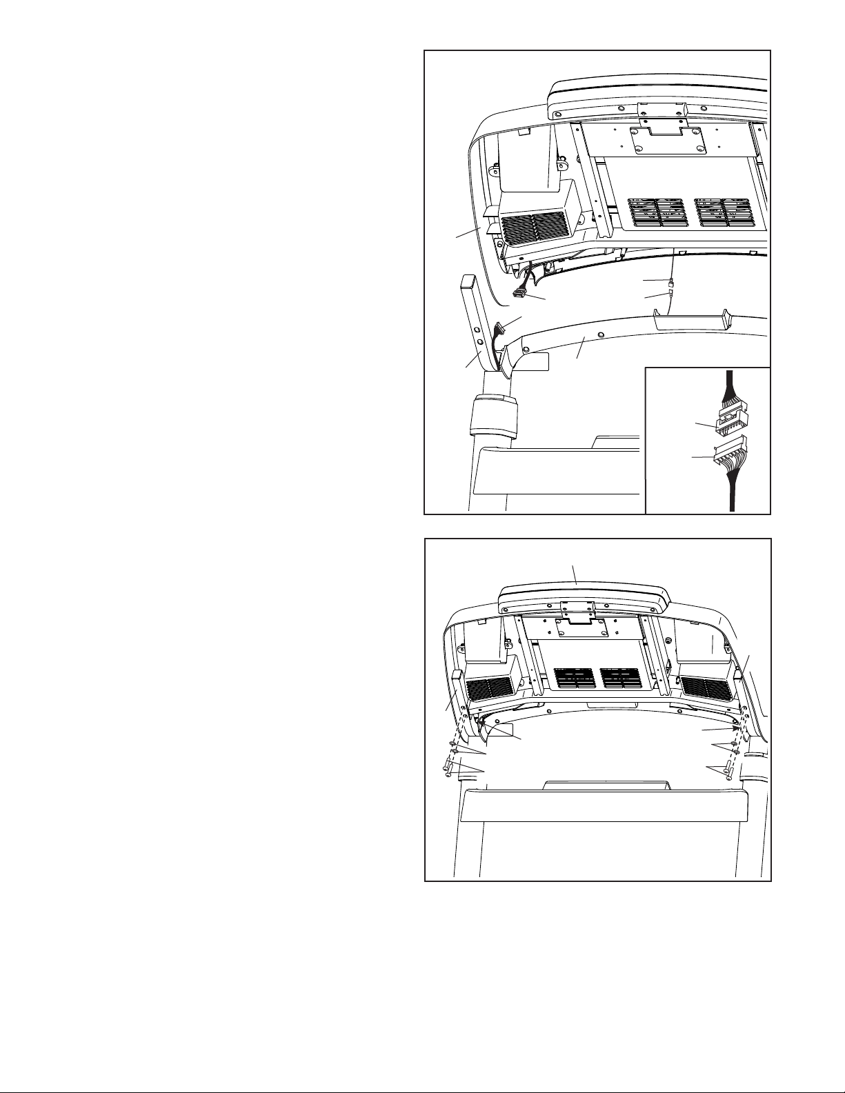
4. Identify the left Tray Bracket (76), which has an
attached tie (C).
IMPORTANT: To avoid damaging the Tray
Bracket (76), do not use power tools.
Attach the left Tray Bracket (76) to the left
Upright (84) with two #8 x 3/8" Machine
Screws (142) and two #8 Flat Washers (23).
IMPORTANT: See the inset drawing. Make
sure that the Tray Bracket is attached with
the Machine Screws through the indicated
holes.
84
90
4
76
C
23
142
142
84
76
23
Attach the right Tray Bracket (76) as
described above. Note: There is not a tie on the
right Tray Bracket.
See the inset drawing. Pull the end of the fan
wire (A) out of the left Upright (84).
84
A
23
C
142
76
8
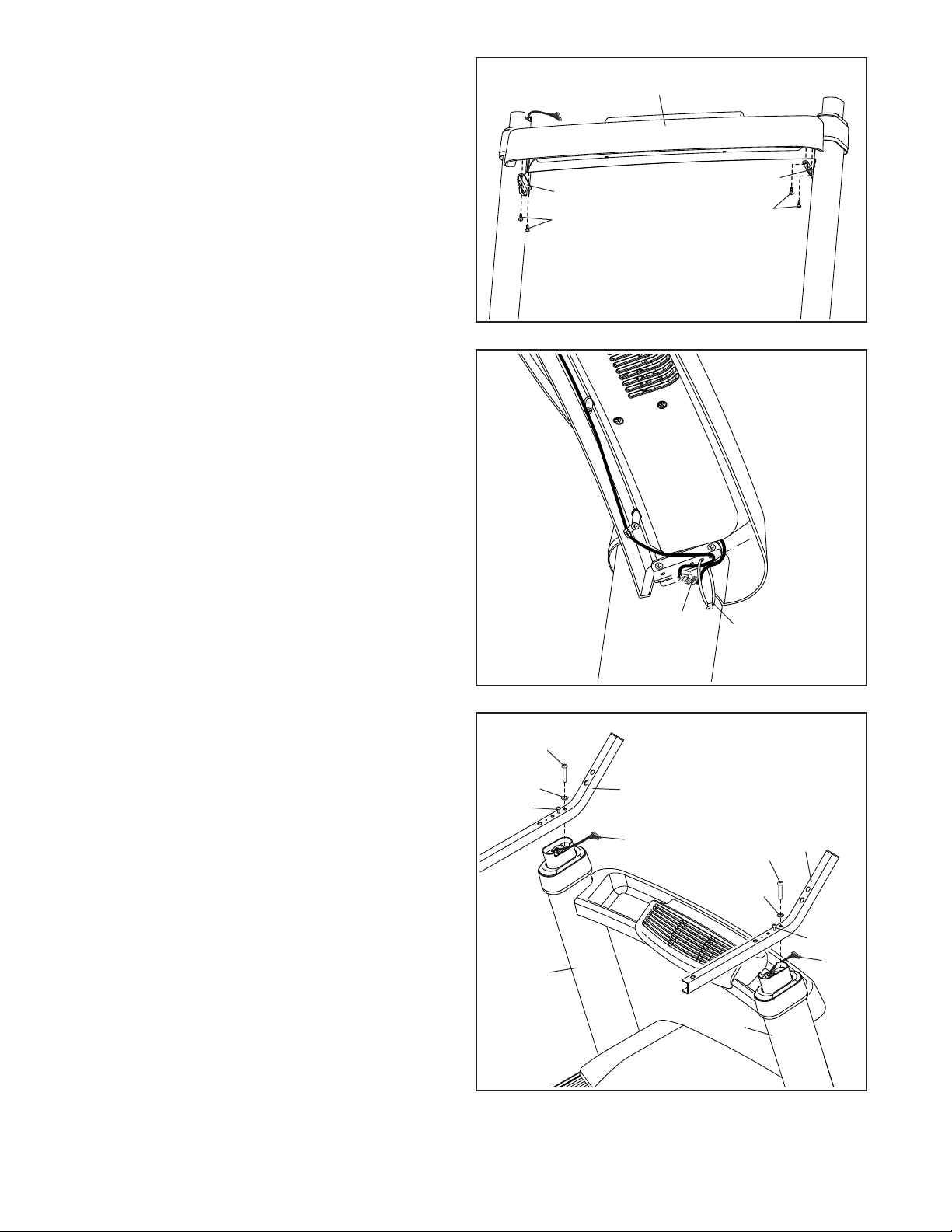
5. Attach the Tray (79) to the left and right Tray
Brackets (76) with four #8 x 3/4" Truss Head
Screw (24); start all four Truss Head Screws,
and then tighten them. Make sure that no
wires are pinched.
5
79
6. Connect the two fan wires (D). The connectors
should slide together easily and snap into
place. If they do not, turn one connector and try
again. IF YOU DO NOT CONNECT THE CONNECTORS PROPERLY, THE CONSOLE MAY
BECOME DAMAGED WHEN YOU TURN ON
THE POWER.
Next, insert the connectors through the looped
tie (C) as shown. Then, pull the tie tight and cut
off the excess tie.
6
Bottom
View
76
24
Front View
D
76
24
C
7. Attach the two Handrails (74) to the left and right
Uprights (84) with two of the 5/16" x 3" Screws
(88) and the two of the 5/16" Star Washers (8)
that you removed in step 3; do not fully tighten
the Screws yet. Be careful not to pinch the
Upright Wire (83) or the fan wire (A). Position
the wires in the cutouts as shown.
Then, remove and discard the two indicated
screws (D).
7
88
8
E
84
74
A
84
88
8
74
E
83
9
8. Set the console assembly (F) face down on a
soft surface to avoid scratching the console
assembly.
Remove and discard the four indicated screws
(G). Then, remove the Pulse Crossbar (80).
8
G
80
F
G
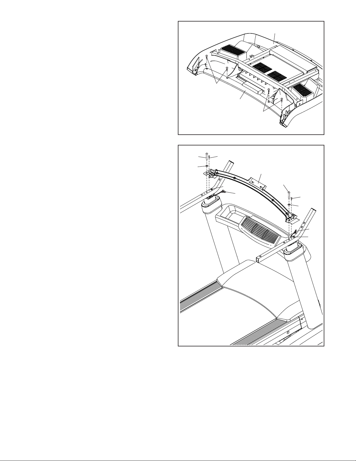
9. IMPORTANT: To avoid damaging the Pulse
Crossbar (80), do not use power tools, and do
not overtighten the #10 x 3/4" Screws (6) or
the 5/16" x 3" Screws (88).
Orient the Pulse Crossbar (80) as shown. Attach
the Pulse Crossbar with two of the 5/16" x 3"
Screws (88) and two of the 5/16" Star Washers
(8) that you removed in step 3, and two #10 x
3/4" Screws (6); start all four Screws, and then
tighten them.
Be careful not to pinch the Upright Wire (83)
or the fan wire (A). Position the wires in the
cutouts as shown.
Then, tighten the other two 5/16" x 3"
Screws (88).
9
88
8
6
80
88
A
88
6
8
83
88
10
10. With the help of a second person, hold the con-
sole assembly (F) near the Handrails (74).
Connect the ground wire (L) from the console
assembly (F) to the Console Ground Wire (152)
on the Pulse Crossbar (80).
See the inset drawing. Connect the Upright
Wire (83) to the console wire (H). The connec-
tors should slide together easily and snap
into place. If they do not, turn one connector
and try again. IF YOU DO NOT CONNECT THE
CONNECTORS PROPERLY, THE CONSOLE
MAY BECOME DAMAGED WHEN YOU TURN
ON THE POWER.
Next, connect the two fan wires (not shown) on
the left side.
10
F
L
H
83
152
11. Attach the console assembly (F) to the Handrails
(74) with four 5/16" x 2" Screws (2) and four
5/16" Star Washers (8); start all four Screws,
and then tighten them. Be careful not to
pinch the wires. Note: The wires should be
positioned between the Handrails and the
plastic console assembly.
Then, insert the wires (D) upward into the con-
sole assembly (F).
11
74
74
80
H
83
F
74
D
8
2
D
8
2
11
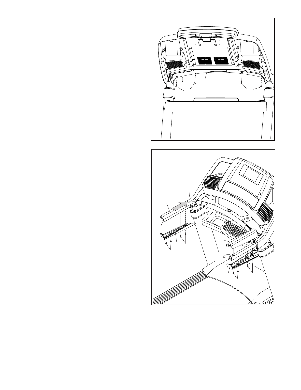
12. Start four #8 x 3/4" Truss Head Screw (24) into
the Pulse Crossbar (80), and then tighten them;
do not overtighten the Truss Head Screws.
12
24
80
24
13. Set the Left Handrail Top Cover (73) on the left
Handrail (74). Start four #8 x 3/4" Truss Head
Screws (24) into the Left Handrail Bottom Cover
(75), the left Handrail, and the Left Handrail Top
Cover. Slide the Left Handrail Top and Bottom
Covers forward against the console assembly (F)
as shown. Then, tighten all four Truss Head
Screws.
Attach the Right Handrail Top and Bottom
Covers (81, 82) to the right Handrail (74) in
the same way.
13
74
73
24
75
24
F
81
74
82
24
24
12
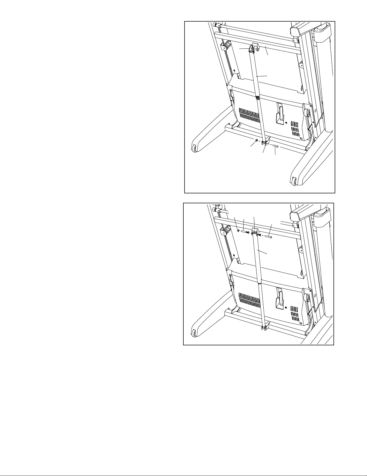
14. Raise the Frame (52) to the position shown.
Have a second person hold the Frame until
step 15 is completed.
14
Remove the 5/16" Nut (9) and the 5/16" x 1 3/4"
Bolt (3) from the bracket on the Uprights (84).
Next, orient the Storage Latch (56) as shown.
Attach the lower end of the Storage Latch (56) to
the bracket on the Uprights (84) with the 5/16" x
1 3/4" Bolt (3) and the 5/16" Nut (9).
Then, raise the Storage Latch (56) to a vertical
position, and remove the tie (I).
15. Remove the 5/16" Nut (9) and the 5/16" x 2 1/4"
Bolt (4) from the bracket on the Frame (52).
Align the upper end of the Storage Latch (56)
with the bracket on the Frame (52), and insert
the 5/16" x 2 1/4" Bolt (4) through the bracket
and the Storage Latch. This will push a spacer
(J) out of the Storage Latch; discard the
spacer.
15
I
52
56
9
84
3
9
52
J
4
56
Next, tighten the 5/16" Nut (9) onto the 5/16" x
2 1/4" Bolt (4). Do not overtighten the Nut; the
Storage Latch (56) must be able to pivot.
Then, lower the Frame (52) (see HOW TO
LOWER THE TREADMILL FOR USE on page
31).
13

16. Press the two tabs on the Tablet Holder (16) into
the slots (K) in the console assembly (F).
16
Attach the Tablet Holder (16) with four #8 x 5/8"
Machine Screws (108). Note: Start the two top
Machine Screws rst, and then start the two
bottom Machine Screws. Be careful not to
overtighten the Machine Screws.
IMPORTANT: The Tablet Holder (16) is
designed for use with most full-size tablets.
Do not place any other electronic device or
object in the Tablet Holder.
17. Make sure that all parts are properly tightened before you use the treadmill. If there are sheets of plastic
on the treadmill decals, remove the plastic. To protect the oor or carpet, place a mat under the treadmill. To
avoid damage to the console, keep the treadmill out of direct sunlight. Keep the included hex keys in a secure
place; one of the hex keys is used to adjust the walking belt (see pages 33 and 34). Note: Extra parts may be
included.
Start First
108
16
K
F
14