


 Loading...
User’s Guide
Part I
Bedside Monitor
BSM-6301/BSM-6501/BSM-6701
BSM-6000 series
BSM-6301A
BSM-6301K
BSM-6501A
BSM-6501K
BSM-6701A
BSM-6701K
0614-900676G

If you have any comments or suggestions on this manual, please contact us at: www.nihonkohden.com
Copyright Notice
The entire contents of this manual are copyrighted by Nihon Kohden. All rights are reserved. No part of this document may be reproduced, stored, or transmitted in any form or by any means (electronic, mechanical, photocopied, recorded, or otherwise) without the prior written permission of Nihon Kohden.
Trademark
The mark printed on the SD card that is used in this instrument is a trademark. The company name and model name are trademarks and registered trademarks of each company.

Contents
|
GENERAL HANDLING PRECAUTIONS.............................................................................. |
i |
|
WARRANTY POLICY.......................................................................................................... |
ii |
|
EMC RELATED CAUTION ................................................................................................. |
iii |
|
Conventions Used in this Manual and Instrument ............................................................. |
vi |
|
Warnings, Cautions and Notes ................................................................................ |
vi |
|
Text Conventions in this Manual............................................................................... |
vi |
|
Explanations of the Symbols in this Manual and Instrument ............................................. |
vii |
|
Related Documentation...................................................................................................... |
xi |
|
Safety Standards ............................................................................................................... |
xi |
|
Safety Information.............................................................................................................. |
xi |
Section 1 |
General................................................................................... |
1.1 |
|
Introduction....................................................................................................................... |
1.3 |
|
General................................................................................................................... |
1.3 |
|
Applications.................................................................................................. |
1.4 |
|
Features....................................................................................................... |
1.4 |
|
Measurement Parameters, and Applicable Units......................................... |
1.6 |
|
Composition..................................................................................................................... |
1.8 |
|
Network Composition....................................................................................................... |
1.9 |
|
Panel Description........................................................................................................... |
1.10 |
|
MU-631R Main Unit.............................................................................................. |
1.10 |
|
Front Panel................................................................................................. |
1.10 |
|
Left Side Panel........................................................................................... |
1.11 |
|
Right Side Panel........................................................................................ |
1.11 |
|
Rear Panel................................................................................................. |
1.12 |
|
MU-651R/MU-671R Main Unit............................................................................. |
1.13 |
|
Front Panel................................................................................................. |
1.13 |
|
Left Side Panel........................................................................................... |
1.14 |
|
Right Side Panel........................................................................................ |
1.14 |
|
Rear Panel................................................................................................. |
1.15 |
|
AY-631P/633P/651P/653P/660P/661P/663P/671P/673P Input Unit.................... |
1.16 |
|
Front Panel................................................................................................. |
1.16 |
|
Using MULTI Sockets for CO Monitoring.................................................... |
1.16 |
|
Using the Output Signal from the ECG/BP OUT Socket............................ |
1.17 |
|
Left Side Panel........................................................................................... |
1.18 |
|
Right Side Panel........................................................................................ |
1.18 |
|
Rear Panel................................................................................................. |
1.19 |
|
AA-672P/AA-674P Smart Expansion Unit............................................................ |
1.19 |
|
Front Panel................................................................................................. |
1.19 |
|
Using MULTI Sockets for CO Monitoring.................................................... |
1.20 |
|
Right Side Panel........................................................................................ |
1.20 |
|
QF series Interface and IF series Communication Cable..................................... |
1.21 |
|
RY-910PA Remote Controller............................................................................... |
1.22 |
|
Basic Operating Concepts.............................................................................................. |
1.23 |
1
2
3
4
5
6
7
8
9
10
11
User’s Guide Part I BSM-6000 |
C. |
CONTENTS |
|
Screen Displays................................................................................................... |
1.23 |
Using Touch Screen Keys .................................................................................... |
1.29 |
Keys on the Bedside Monitor................................................................................ |
1.30 |
Using the Remote Control.................................................................................... |
1.31 |
Using the Mouse.................................................................................................. |
1.31 |
Using the Data Acquisition Unit............................................................................ |
1.32 |
Using the MENU Window..................................................................................... |
1.33 |
Transport Function.......................................................................................................... |
1.34 |
Overview.............................................................................................................. |
1.34 |
Requirements....................................................................................................... |
1.34 |
Necessary Settings Before Use........................................................................... |
1.34 |
Transported Data and Settings............................................................................. |
1.35 |
Sending Data to a CNS-9701 Central Monitor..................................................... |
1.36 |
Patient Authentication........................................................................................... |
1.37 |
Preparing for Removing the Input Unit................................................................. |
1.41 |
Enabling the Input Unit......................................................................................... |
1.42 |
When the Input Unit is Disabled................................................................. |
1.42 |
Enabling the Input Unit............................................................................... |
1.42 |
Section 2 |
Preparation............................................................................. |
2.1 |
|
Preparation Flowchart...................................................................................................... |
2.2 |
|
Installation Conditions...................................................................................................... |
2.3 |
|
Inserting and Removing the Battery Pack........................................................................ |
2.5 |
|
Battery Handling and Operation............................................................................. |
2.5 |
|
Safety Information........................................................................................ |
2.5 |
|
Battery Pack Handling Procedures.............................................................. |
2.6 |
|
When Not Using the Monitor or Battery Pack.............................................. |
2.6 |
|
Inserting and Removing the Battery Packs............................................................ |
2.6 |
|
Inserting the Battery Pack...................................................................................... |
2.7 |
|
Removing the Battery Pack.................................................................................... |
2.8 |
|
Inserting and Removing the Input Unit............................................................................ |
2.9 |
|
Inserting the Input Unit........................................................................................... |
2.9 |
|
Removing the Input Unit......................................................................................... |
2.9 |
|
When the Transport Function is Enabled................................................... |
2.10 |
|
Preparing the Optional Recorder.................................................................................... |
2.11 |
|
Installing the Recorder Module............................................................................ |
2.11 |
|
Loading Recording Paper..................................................................................... |
2.11 |
|
Preparing the Remote Control........................................................................................ |
2.13 |
|
Installing the Batteries.......................................................................................... |
2.13 |
|
Setting the Remote Control Channel................................................................... |
2.14 |
|
Attaching the Remote Control Channel Label to the Bedside Monitor................. |
2.14 |
|
Assigning Functions to the Customized Keys...................................................... |
2.14 |
|
Power.............................................................................................................................. |
2.15 |
|
Connecting the Power Cord and Grounding the Monitor...................................... |
2.15 |
|
Connecting the Power Cord....................................................................... |
2.15 |
|
Grounding the Monitor............................................................................... |
2.16 |
|
Turning the Power On........................................................................................... |
2.16 |
|
Check Before Turning On the Power.......................................................... |
2.16 |
C. |
User’s Guide Part I BSM-6000 |

|
|
CONTENTS |
|
Turning the Power On................................................................................. |
2.17 |
|
AUTO ADMIT Setting................................................................................. |
2.18 |
|
Check After Turning On the Power and During Monitoring........................ |
2.18 |
|
Power and Battery Status Indications.................................................................. |
2.19 |
|
When the “BATTERY WEAK” Message Appears....................................... |
2.20 |
|
Charging the Battery Pack......................................................................... |
2.20 |
|
Monitor Status on Power Interruption................................................................... |
2.21 |
|
Turning the Power Off........................................................................................... |
2.22 |
|
Check After/Before Turning the Power Off................................................. |
2.22 |
Section 3 |
Necessary Settings Before Monitoring................................ |
3.1 |
|
Changing Date and Time.................................................................................................. |
3.2 |
|
Changing Sound Volume Settings.................................................................................... |
3.3 |
|
Changing the Screen Brightness...................................................................................... |
3.4 |
|
Changing Waveform Display Settings.............................................................................. |
3.5 |
|
Entering Patient Information............................................................................................. |
3.7 |
|
Displaying the PATIENT INFO Page....................................................................... |
3.8 |
|
Closing the PATIENT INFO Page........................................................................... |
3.8 |
|
Entering the Patient Information............................................................................. |
3.9 |
|
Entering the Patient ID................................................................................. |
3.9 |
|
Entering the Patient Name......................................................................... |
3.10 |
|
Entering the Date of Birth and Age............................................................ |
3.11 |
|
Entering the Height and Weight................................................................. |
3.13 |
|
Entering the Gender................................................................................... |
3.13 |
|
Entering the Pacemaker Use..................................................................... |
3.14 |
|
Deleting Data.................................................................................................................. |
3.16 |
|
Suspended Alarms after Deleting Data...................................................... |
3.18 |
1
2
3
4
5
6
7
8
9
10
11
Section 4 |
Home Screen.......................................................................... |
4.1 |
|
Safety Precautions for Monitoring.................................................................................... |
4.3 |
|
Using an Electrosurgical Unit....................................................................... |
4.3 |
|
Using a Defibrillator...................................................................................... |
4.3 |
|
Overview........................................................................................................................... |
4.4 |
|
Home Screen......................................................................................................... |
4.4 |
|
Review Windows.................................................................................................... |
4.4 |
|
Sync Sound............................................................................................................ |
4.4 |
|
Adjusting the Sync and Alarm Sound Volume........................................................ |
4.4 |
|
Changing Settings and Performing Other Tasks During Monitoring....................... |
4.4 |
|
Site Mode............................................................................................................... |
4.5 |
|
Recording/Printing on the Home Screen................................................................ |
4.5 |
|
Interbed Monitoring................................................................................................ |
4.5 |
|
Home Screen................................................................................................................... |
4.6 |
|
Settings for the Home Screen ............................................................................... |
4.7 |
|
Waveform Sweep Mode and Speed............................................................. |
4.7 |
|
Waveform Display on the Home Screen...................................................... |
4.7 |
|
Pacing Mark Position on the ECG Waveform............................................... |
4.7 |
User’s Guide Part I BSM-6000 |
C. |
CONTENTS |
|
ST Waveform and Reference ST Recall Waveform Display on the |
|
Home Screen On or Off............................................................................... |
4.7 |
Blood Pressure Waveform Display Mode..................................................... |
4.7 |
PPV or SPV Display on the Home Screen................................................... |
4.8 |
Pulse Rate Display on the Home Screen..................................................... |
4.8 |
Current Average CO and PCWP Values Display on the Home Screen........ |
4.8 |
Trendgraph/PWTT Trendgraph/OCRG Display on the Home Screen On |
|
or Off............................................................................................................ |
4.8 |
Scale Setting for the Trendgraph on the Home Screen................................ |
4.9 |
Parameter Colors......................................................................................... |
4.9 |
Waveform Sensitivity.................................................................................... |
4.9 |
Displaying Other Windows from the Home Screen.............................................. |
4.10 |
Displaying PWTT Trendgraph......................................................................................... |
4.11 |
Displaying OCRG........................................................................................................... |
4.13 |
Freezing Waveforms....................................................................................................... |
4.14 |
Using Sleep Mode.......................................................................................................... |
4.15 |
Turning Sleep Mode On............................................................................. |
4.15 |
Turning Sleep Mode Off............................................................................. |
4.16 |
Displaying the LARGE NUMERICS Screen................................................................... |
4.17 |
Section 5 |
Alarm Function...................................................................... |
5.1 |
|
Overview of Alarms.......................................................................................................... |
5.4 |
|
What is an Alarm.................................................................................................... |
5.4 |
|
Alarm Level............................................................................................................ |
5.5 |
|
Alarm Priority......................................................................................................... |
5.5 |
|
Alarm Sound/Alarm Indicator....................................................................... |
5.5 |
|
Alarm Messages on the Screen................................................................... |
5.5 |
|
Silencing/Suspending Alarms................................................................................ |
5.5 |
|
Alarm Master.......................................................................................................... |
5.6 |
|
Automatic Recording.............................................................................................. |
5.7 |
|
Alarm Setting.......................................................................................................... |
5.7 |
|
Canceling the Technical Alarm............................................................................... |
5.8 |
|
Adjusting Alarm Sound Volume.............................................................................. |
5.8 |
|
Alarm Activation after Power On............................................................................ |
5.8 |
|
ALARM HISTORY Window..................................................................................... |
5.8 |
|
Interbed Alarm........................................................................................................ |
5.9 |
|
Alarm Types.................................................................................................................... |
5.10 |
|
Vital Signs Alarms................................................................................................ |
5.10 |
|
Arrhythmia Alarms................................................................................................ |
5.10 |
|
Technical Alarms.................................................................................................. |
5.11 |
|
ECG Related Alarms.................................................................................. |
5.11 |
|
Respiration Related Alarms....................................................................... |
5.11 |
|
CO2 Related Alarms................................................................................... |
5.12 |
|
Microcap® Related Alarms......................................................................... |
5.12 |
|
SpO2 Related Alarms................................................................................. |
5.12 |
|
NIBP Related Alarms................................................................................. |
5.13 |
|
IBP Related Alarms.................................................................................... |
5.13 |
|
Temperature Related Alarms..................................................................... |
5.13 |
C. |
User’s Guide Part I BSM-6000 |

|
CONTENTS |
BIS Related Alarms.................................................................................... |
5.13 |
CO Related Alarms.................................................................................... |
5.14 |
Gas Related Alarms................................................................................... |
5.14 |
O2 Related Alarms..................................................................................... |
5.15 |
VENT Related Alarms................................................................................ |
5.15 |
TOF Related Alarms.................................................................................. |
5.15 |
CCO Related Alarms................................................................................. |
5.15 |
PiCCO Related Alarms.............................................................................. |
5.16 |
FLOW/Paw Related Alarms....................................................................... |
5.16 |
EEG Related Alarms.................................................................................. |
5.16 |
tcPO2/tcPCO2 Related Alarms................................................................... |
5.17 |
Other Alarms........................................................................................................ |
5.17 |
Messages............................................................................................................. |
5.18 |
ECG Related Messages............................................................................ |
5.18 |
Respiration Related Messages.................................................................. |
5.18 |
CO2 Related Messages.............................................................................. |
5.18 |
SpO2 Related Messages............................................................................ |
5.19 |
NIBP Related Messages............................................................................ |
5.19 |
IBP Related Message................................................................................ |
5.19 |
BIS Related Messages.............................................................................. |
5.20 |
O2 Related Messages................................................................................ |
5.20 |
CO Related Messages............................................................................... |
5.20 |
Gas Related Messages.............................................................................. |
5.21 |
FLOW/Paw Related Messages.................................................................. |
5.21 |
EEG Related Messages............................................................................. |
5.21 |
Microcap® Related Messages.................................................................... |
5.22 |
Other Messages......................................................................................... |
5.22 |
Alarm Indications............................................................................................................ |
5.23 |
Overview.............................................................................................................. |
5.23 |
Individual Alarm Indications................................................................................. |
5.24 |
Vital Signs Alarms...................................................................................... |
5.25 |
Arrhythmia Alarms...................................................................................... |
5.29 |
Technical Alarms........................................................................................ |
5.30 |
Other Alarms.............................................................................................. |
5.37 |
Interbed Alarms.......................................................................................... |
5.37 |
Alarm Control Marks............................................................................................ |
5.37 |
Individual Vital Signs Alarm Off Marks....................................................... |
5.38 |
Flow of Alarm Function........................................................................................ |
5.39 |
Silencing and Suspending Alarms.................................................................................. |
5.40 |
Overview.............................................................................................................. |
5.40 |
Silencing an Alarm..................................................................................... |
5.40 |
Suspending Alarms.................................................................................... |
5.40 |
Silencing Alarms After Alarm Occurrence............................................................ |
5.43 |
Silencing an Alarm..................................................................................... |
5.43 |
Canceling Alarm Silence............................................................................ |
5.44 |
Suspending Alarms Before Alarm Occurrence.................................................... |
5.44 |
Suspending Alarms.................................................................................... |
5.44 |
Suspending All Alarms Indefinitely............................................................. |
5.44 |
1
2
3
4
5
6
7
8
9
10
11
User’s Guide Part I BSM-6000 |
C. |
CONTENTS |
|
Suspending All Alarms and NIBP STAT and Auto Measurement |
|
Indefinitely.................................................................................................. |
5.47 |
Turning Automatic Alarm Recording On/Off................................................................... |
5.49 |
Setting Alarms................................................................................................................ |
5.50 |
Overview.............................................................................................................. |
5.50 |
Alarm Limits Ranges............................................................................................ |
5.50 |
Vital Signs Alarms...................................................................................... |
5.51 |
Arrhythmia Alarms...................................................................................... |
5.56 |
Setting Vital Signs Alarms Individually................................................................. |
5.57 |
Setting All Vital Signs Alarms to a Preset Pattern (Alarm Master)....................... |
5.58 |
Setting Arrhythmia Alarms Individually................................................................. |
5.59 |
Setting All Arrhythmia Alarms to a Preset Pattern (Alarm Master)....................... |
5.60 |
Section 6 |
Review Windows.................................................................... |
6.1 |
|
General............................................................................................................................. |
6.3 |
|
Transport................................................................................................................ |
6.4 |
|
Review Recording.................................................................................................. |
6.5 |
|
Event Bar.......................................................................................................................... |
6.6 |
|
Selecting the Event Display Position on the Event Bar.......................................... |
6.6 |
|
Changing the Event Bar Time Interval.................................................................... |
6.7 |
|
Scrolling the Event Bar........................................................................................... |
6.7 |
|
Trend Window................................................................................................................... |
6.8 |
|
GRAPH 1, GRAPH 2, GRAPH 3 Page................................................................... |
6.8 |
|
Displaying the GRAPH 1, GRAPH 2 or GRAPH 3 Page............................ |
6.10 |
|
Selecting Parameters for the Trendgraph Display...................................... |
6.11 |
|
Changing the Trendgraph Scale................................................................. |
6.12 |
|
Changing the Trendgraph Display Format.................................................. |
6.13 |
|
Recording the Trendgraph.......................................................................... |
6.14 |
|
Printing the Trendgraph.............................................................................. |
6.15 |
|
TABLE 1, TABLE 2, TABLE 3 Page...................................................................... |
6.17 |
|
Displaying the TABLE 1, TABLE 2 or TABLE 3 Page.................................. |
6.18 |
|
Scrolling the Trend Table............................................................................ |
6.19 |
|
Selecting Parameters for the Trend Table Display...................................... |
6.19 |
|
Selecting the Measurement Interval.......................................................... |
6.20 |
|
Recording a Trend Table............................................................................. |
6.21 |
|
Printing a Trend Table................................................................................. |
6.21 |
|
NIBP TREND Page.............................................................................................. |
6.23 |
|
Displaying the NIBP TREND Page............................................................. |
6.24 |
|
Scrolling the NIBP Trend Table................................................................... |
6.25 |
|
Selecting Parameters for the NIBP Trend Display...................................... |
6.25 |
|
Recording a NIBP Trend Table................................................................... |
6.26 |
|
Printing a NIBP Trend Table....................................................................... |
6.27 |
|
HEMO Page......................................................................................................... |
6.29 |
|
Displaying the HEMO Page........................................................................ |
6.29 |
|
Scrolling the Hemodynamics Table............................................................ |
6.30 |
|
Explanation of the Hemodynamics Table................................................... |
6.31 |
|
Recording a Hemodynamics Table............................................................. |
6.32 |
|
Printing a Hemodynamics Table................................................................. |
6.33 |
C. |
User’s Guide Part I BSM-6000 |

CONTENTS |
|
LUNG TREND Page............................................................................................. |
6.34 |
Displaying the LUNG TREND Page........................................................... |
6.34 |
Explanation of the Lung Trend Table.......................................................... |
6.35 |
Recording the Lung Trend Table................................................................. |
6.36 |
Printing a Lung Trend Table........................................................................ |
6.37 |
Arrhythmia Recall Window.............................................................................................. |
6.38 |
General................................................................................................................. |
6.38 |
Arrhythmia List........................................................................................... |
6.38 |
Displaying the Arrhythmia Recall Window............................................................ |
6.40 |
Selecting the Arrhythmia Types to be Saved as a Recall File.............................. |
6.41 |
Scrolling the Arrhythmia Recall Files.................................................................... |
6.41 |
Displaying the Actual Size Waveform of the Selected Arrhythmia Recall File...... |
6.42 |
Arrhythmia Waveform Annotation............................................................... |
6.42 |
Recording or Printing the Arrhythmia Recall Waveform....................................... |
6.42 |
Recording on the ARRHYTH HISTORY Window....................................... |
6.42 |
Printing on the ARRHYTH HISTORY Window........................................... |
6.44 |
Recording on the Actual Size ECG Waveform Window............................. |
6.45 |
Printing on the Actual Size ECG Waveform Window.................................. |
6.46 |
Alarm History Window.................................................................................................... |
6.47 |
Displaying the ALARM HISTORY Window........................................................... |
6.47 |
Scrolling the Alarm History Files.......................................................................... |
6.48 |
Recording the Alarm History File......................................................................... |
6.48 |
Full Disclosure Window.................................................................................................. |
6.50 |
Displaying the FULL DISC Window...................................................................... |
6.50 |
Scrolling the Full Disclosure Waveform................................................................ |
6.52 |
Selecting the Parameters to be Saved for Full Disclosure................................... |
6.53 |
Recording or Printing the Full Disclosure Waveform............................................ |
6.54 |
Recording the Full Disclosure Waveform................................................... |
6.54 |
Printing the Full Disclosure Waveform....................................................... |
6.55 |
Recording or Printing the Enlarged ECG Waveform............................................ |
6.57 |
Recording the Enlarged ECG Waveform.................................................... |
6.57 |
Printing the Enlarged ECG Waveform........................................................ |
6.58 |
ST Level Recall Window................................................................................................. |
6.60 |
Displaying the ST Window.................................................................................... |
6.61 |
Scrolling the ST Level Recall File......................................................................... |
6.62 |
Displaying the ST Point........................................................................................ |
6.62 |
Displaying the ST Recall Waveform on the Home Screen................................... |
6.63 |
Saving as Reference ST Recall File..................................................................... |
6.64 |
Displaying the Reference ST Recall Waveform on the Home Screen.................. |
6.65 |
Printing the ST Level Recall File.......................................................................... |
6.66 |
OCRG Window............................................................................................................... |
6.68 |
Displaying the OCRG Window............................................................................. |
6.68 |
Selecting the OCRG Trendgraph Type................................................................. |
6.69 |
Changing the Trendgraph Scale for Heart Rate and SpO2 ................................... |
6.70 |
Recording or Printing the OCRG Trend................................................................ |
6.71 |
Recording the OCRG Trend....................................................................... |
6.71 |
Printing the OCRG Trend........................................................................... |
6.72 |
1
2
3
4
5
6
7
8
9
10
11
User’s Guide Part I BSM-6000 |
C. |
CONTENTS
Section 7 |
12 Lead Analysis/12 Lead Windows..................................... |
7.1 |
|
12 Lead Analysis Window................................................................................................ |
7.2 |
|
Preparation Flowchart............................................................................................ |
7.2 |
|
Displaying the 12 LEAD ANALYSIS Window.......................................................... |
7.3 |
|
Entering the Patient’s Date of Birth and Gender.................................................... |
7.4 |
|
Displaying the PATIENT INFO Window........................................................ |
7.4 |
|
Entering the Date of Birth and Age.............................................................. |
7.4 |
|
Entering the Gender..................................................................................... |
7.4 |
|
Performing 12 Lead ECG Interpretation................................................................. |
7.5 |
|
Recording or Printing the 12 Lead ECG Waveform................................................ |
7.6 |
|
Recording the 12 Lead ECG Waveforms..................................................... |
7.6 |
|
Printing the 12 Lead ECG Waveforms......................................................... |
7.7 |
|
12 LEAD Window............................................................................................................. |
7.9 |
|
Displaying the 12 LEAD Window............................................................................ |
7.9 |
|
12 LEAD Page...................................................................................................... |
7.10 |
|
Scrolling the 12 Lead Data File.................................................................. |
7.10 |
|
Recording the 12 Lead Data...................................................................... |
7.10 |
|
ANALYSIS WAVE Page........................................................................................ |
7.11 |
|
Recording or Printing the 12 Lead Waveform....................................................... |
7.12 |
|
Recording the 12 Lead Waveform.............................................................. |
7.12 |
|
Printing the 12 Lead Waveform.................................................................. |
7.13 |
|
REPORT Page..................................................................................................... |
7.14 |
|
Recording or Printing the 12 Lead Interpretation Results.................................... |
7.14 |
|
Recording the 12 Lead Interpretation Results........................................... |
7.14 |
|
Printing the 12 Lead Interpretation Results................................................ |
7.15 |
|
AVERAGE WAVE Page........................................................................................ |
7.16 |
|
Printing the Averaged ECGs...................................................................... |
7.16 |
Section 8 |
Drug/Lung Function Windows.............................................. |
8.1 |
|
DRUG Window................................................................................................................. |
8.2 |
|
Drug Titration Initial Settings.................................................................................. |
8.3 |
|
Flow Rate Equations.............................................................................................. |
8.4 |
|
Displaying the DRUG Window.......................................................................................... |
8.6 |
|
Selecting the Drug............................................................................................................ |
8.9 |
|
Assigning a Drug Name and Dosage Unit to DRUG A to D........................................... |
8.10 |
|
Changing the Settings.................................................................................................... |
8.12 |
|
Changing the Drug Amount, Solution Amount, Dosage, Flow Rate and |
|
|
Weight.................................................................................................................. |
8.12 |
|
Changing the Dose Step...................................................................................... |
8.13 |
|
Unit and Setting Range........................................................................................ |
8.13 |
|
Drug Amount, Dosage and Step................................................................ |
8.13 |
|
Solution Amount, Flow Rate and Weight.................................................... |
8.14 |
|
LUNG FUNCTION Window............................................................................................ |
8.15 |
|
Displaying the LUNG FUNCTION Window........................................................... |
8.15 |
|
Entering the Data................................................................................................. |
8.17 |
|
Explanation of the DATA ENTRY Items...................................................... |
8.17 |
|
Checking the Calculation Results......................................................................... |
8.18 |
|
Explanation of the CALCULATION RESULTS........................................... |
8.18 |
C. |
|
User’s Guide Part I BSM-6000 |
|
|
CONTENTS |
|
Adding the Calculation Results to the LUNG TREND Table................................. |
8.18 |
|
Displaying the LUNG TREND Table..................................................................... |
8.19 |
|
Recording the Calculation Results and Entered Data.......................................... |
8.20 |
Section 9 |
Interbed Window.................................................................... |
9.1 |
|
Registering Interbed Beds................................................................................................ |
9.3 |
|
Removing an Interbed Bed..................................................................................... |
9.3 |
|
Displaying the Numeric Data of All Interbed Beds............................................................ |
9.4 |
|
Displaying the Interbed Bed Data..................................................................................... |
9.5 |
|
Interbed Alarm.................................................................................................................. |
9.7 |
|
Settings Related to Interbed Alarm........................................................................ |
9.8 |
Section 10 |
Recording............................................................................. |
10.1 |
|
Overview of Recording................................................................................................... |
10.2 |
|
Recording Modes................................................................................................. |
10.3 |
|
Manual Waveform Recording/Printing........................................................ |
10.5 |
|
Recording/Printing on the 12 LEAD ANALYSIS Window........................... |
10.5 |
|
Recording/Printing on the Review Windows other than 12 Lead |
|
|
Window...................................................................................................... |
10.5 |
|
Recording/Printing on the 12 LEAD Window............................................. |
10.5 |
|
Recording on the LUNG FUNCTION Window............................................ |
10.5 |
|
Recording/Printing PWTT Trendgraph....................................................... |
10.6 |
|
Recording/Printing OCRG.......................................................................... |
10.6 |
|
Recording on the CO Window.................................................................... |
10.6 |
|
Recording on the TOF Window.................................................................. |
10.6 |
|
Recording on the CCO Window................................................................. |
10.6 |
|
Recording on the FLOW Window............................................................... |
10.6 |
|
Recording on the EEG Window................................................................. |
10.7 |
|
Periodic Recording..................................................................................... |
10.8 |
|
Alarm Recording........................................................................................ |
10.9 |
|
Recording Mode Annotations............................................................................. |
10.11 |
|
Recording Priority............................................................................................... |
10.12 |
|
Recording Sensitivity.......................................................................................... |
10.12 |
|
Recording Speed............................................................................................... |
10.12 |
|
Recording Related Message.............................................................................. |
10.12 |
|
Recorded/Printed Data....................................................................................... |
10.13 |
|
Changing the Recording Speed................................................................................... |
10.14 |
|
Changing the Recording Pattern.................................................................................. |
10.15 |
|
Manually Recording/Printing Waveforms...................................................................... |
10.16 |
|
Recording Waveforms on the Optional Recorder............................................... |
10.16 |
|
Recording Waveforms on the Bedside Monitor with No Recorder..................... |
10.17 |
|
Manual Printing on the Network Printer............................................................. |
10.17 |
|
Setting Periodic Recording........................................................................................... |
10.18 |
|
Changing Settings for Automatic Periodic Recording......................................... |
10.19 |
|
Printing on a Network Printer....................................................................................... |
10.20 |
1
2
3
4
5
6
7
8
9
10
11
User’s Guide Part I BSM-6000 |
C. |
CONTENTS
Section 11 Reference............................................................................. |
11.1 |
Clock Accuracy .............................................................................................................. |
11.2 |
Periodical Replacement Schedule ................................................................................. |
11.3 |
Repair Parts Availability Policy....................................................................................... |
11.3 |
C.10 |
User’s Guide Part I BSM-6000 |
GENERAL HANDLING PRECAUTIONS
This device is intended for use only by qualified medical personnel.
Use only Nihon Kohden approved products with this device. Use of non-approved products or in a non-approved manner may affect the performance specifications of the device. This includes, but is not limited to, batteries, recording paper, pens, extension cables, electrode leads, input boxes and AC power.
Please read these precautions thoroughly before attempting to operate the instrument.
1.To safely and effectively use the instrument, its operation must be fully understood.
2.When installing or storing the instrument, take the following precautions:
(1)Avoid moisture or contact with water, extreme atmospheric pressure, excessive humidity and temperatures, poorly ventilated areas, and dust, saline or sulphuric air.
(2)Place the instrument on an even, level floor. Avoid vibration and mechanical shock, even during transport.
(3)Avoid placing in an area where chemicals are stored or where there is danger of gas leakage.
(4)The power line source to be applied to the instrument must correspond in frequency and voltage to product specifications, and have sufficient current capacity.
(5)Choose a room where a proper grounding facility is available.
3.Before Operation
(1)Check that the instrument is in perfect operating order.
(2)Check that the instrument is grounded properly.
(3)Check that all cords are connected properly.
(4)Pay extra attention when the instrument is combined with other instruments to avoid misdiagnosis or other problems.
(5)All circuitry used for direct patient connection must be doubly checked.
(6)Check that battery level is acceptable and battery condition is good when using battery-operated models.
4.During Operation
(1)Both the instrument and the patient must receive continual, careful attention.
(2)Turn power off or remove electrodes and/or transducers when necessary to assure the patient’s safety.
(3)Avoid direct contact between the instrument housing and the patient.
5.To Shutdown After Use
(1)Turn power off with all controls returned to their original positions.
(2)Remove the cords gently; do not use force to remove them.
(3)Clean the instrument together with all accessories for their next use.
6.The instrument must receive expert, professional attention for maintenance and repairs. When the instrument is not functioning properly, it should be clearly marked to avoid operation while it is out of order.
7.The instrument must not be altered or modified in any way.
8.Maintenance and Inspection
(1)The instrument and parts must undergo regular maintenance inspection at least every 6 months.
(2)If stored for extended periods without being used, make sure prior to operation that the instrument is in perfect operating condition.
User’s Guide Part I BSM-6000 |
i |

(3)Technical information such as parts list, descriptions, calibration instructions or other information is available for qualified user technical personnel upon request from your Nihon Kohden representative.
9.When the instrument is used with an electrosurgical instrument, pay careful attention to the application and/or location of electrodes and/or transducers to avoid possible burn to the patient.
10.When the instrument is used with a defibrillator, make sure that the instrument is protected against defibrillator discharge. If not, remove patient cables and/or transducers from the instrument to avoid possible damage.
WARRANTY POLICY
Nihon Kohden Corporation (NKC) shall warrant its products against all defects in materials and workmanship for one year from the date of delivery. However, consumable materials such as recording paper, ink, stylus and battery are excluded from the warranty.
NKC or its authorized agents will repair or replace any products which prove to be defective during the warranty period, provided these products are used as prescribed by the operating instructions given in the operator’s and service manuals.
No other party is authorized to make any warranty or assume liability for NKC’s products. NKC will not recognize any other warranty, either implied or in writing. In addition, service, technical modification or any other product change performed by someone other than NKC or its authorized agents without prior consent of NKC may be cause for voiding this warranty.
Defective products or parts must be returned to NKC or its authorized agents, along with an explanation of the failure. Shipping costs must be pre-paid.
This warranty does not apply to products that have been modified, disassembled, reinstalled or repaired without Nihon Kohden approval or which have been subjected to neglect or accident, damage due to accident, fire, lightning, vandalism, water or other casualty, improper installation or application, or on which the original identification marks have been removed.
In the USA and Canada other warranty policies may apply.
CAUTION
United States law restricts this product to sale by or on the order of a physician.
ii |
User’s Guide Part I BSM-6000 |

EMC RELATED CAUTION
This equipment and/or system complies with IEC 60601-1-2 International Standard for electromagnetic compatibility for medical electrical equipment and/or system. However, an electromagnetic environment that exceeds the limits or levels stipulated in IEC 60601-1-2, can cause harmful interference to the equipment and/or system or cause the equipment and/or system to fail to perform its intended function or degrade its intended performance. Therefore, during the operation of the equipment and/or system, if there is any undesired deviation from its intended operational performance, you must avoid, identify and resolve the adverse electromagnetic effect before continuing to use the equipment and/or system.
The following describes some common interference sources and remedial actions:
1.Strong electromagnetic interference from a nearby emitter source such as an authorized radio station or cellular phone:
Install the equipment and/or system at another location. Keep the emitter source such as cellular phone away from the equipment and/or system, or turn off the cellular phone.
2.Radio-frequency interference from other equipment through the AC power supply of the equipment and/or system:
Identify the cause of this interference and if possible remove this interference source. If this is not possible, use a different power supply.
3.Effect of direct or indirect electrostatic discharge:
Make sure all users and patients in contact with the equipment and/or system are free from direct or indirect electrostatic energy before using it. A humid room can help lessen this problem.
4.Electromagnetic interference with any radio wave receiver such as radio or television:
If the equipment and/or system interferes with any radio wave receiver, locate the equipment and/or system as far as possible from the radio wave receiver.
5.Interference of lightning:
When lightning occurs near the location where the equipment and/or system is installed, it may induce an excessive voltage in the equipment and/or system. In such a case, disconnect the AC power cord from the equipment and/or system and operate the equipment and/or system by battery power, or use an uninterruptible power supply.
6.Use with other equipment:
When the equipment and/or system is adjacent to or stacked with other equipment, the equipment and/or system may affect the other equipment. Before use, check that the equipment and/or system operates normally with the other equipment.
7.Use of unspecified accessory, transducer and/or cable:
When an unspecified accessory, transducer and/or cable is connected to this equipment and/or system, it may cause increased electromagnetic emission or decreased electromagnetic immunity. The specified configuration of this equipment and/or system complies with the electromagnetic requirements with the specified configuration. Only use this equipment and/or system with the specified configuration.
User’s Guide Part I BSM-6000 |
iii |

Caution - continued
8.Use of unspecified configuration:
When the equipment and/or system is used with the unspecified system configuration different than the configuration of EMC testing, it may cause increased electromagnetic emission or decreased electromagnetic immunity. Only use this equipment and/or system with the specified configuration.
9.Measurement with excessive sensitivity:
The equipment and/or system is designed to measure bioelectrical signals with a specified sensitivity. If the equipment and/or system is used with excessive sensitivity, artifact may appear by electromagnetic interference and this may cause mis-diagnosis. When unexpected artifact appears, inspect the surrounding electromagnetic conditions and remove this artifact source.
If the above suggested remedial actions do not solve the problem, consult your Nihon Kohden representative for additional suggestions.
In IEC 60601-1-2 Medical Electronic Equipment, Part 1: General Requirements for Safety, 2. Collateral Standard: Electromagnetic compatibility-Requirements and test. Section 36. 202. 2 Radiated radiofrequency electromagnetic fields, PATIENT COUPLED EQUIPMENT and/or SYSTEMS applicable IMMUNITY test methods are under consideration at SC62A/WG13. The 3 V/m IMMUNITY level may be inappropriate especially when measuring SpO2 because physiological signals can be much smaller than those induced by a 3 V/m electromagnetic field.
When measuring SpO2, various interference may produce false waveforms which look like pulse waveforms. SpO2 value and pulse rate may be measured from these false waveforms, causing the alarm to function improperly.
When installing the monitor, avoid locations where the monitor may receive strong electromagnetic interference such as radio or TV stations, cellular phone or mobile two-way radios.
BSM-6301 and BSM-6501 (JA-690PA/JA-694PA data acquisition unit, QE-910P BIS processor and QI320PA wireless LAN station are not connected) comply with International Standard IEC 60601-1-2: 2001 and Amendment 1: 2004 which requires CISPR11, Group 1, Class B. Class B EQUIPMENT is equipment suitable for use in domestic establishments and in establishments directly connected to a low voltage power supply network which supplies buildings used for domestic purposes.
BSM-6301, BSM-6501 (JA-690PA/JA-694PA data acquisition unit, QE-910P BIS processor and QI-320PA wireless LAN station are connected) and BSM-6701 comply with International Standard IEC 60601-1-
2: 2001 and Amendment 1: 2004 which requires CISPR11, Group 1, Class A. Class A EQUIPMENT is equipment suitable for use in industrial or light industrial establishments and commercial environment.
BSM-6301 and BSM-6501 (when QE-910P and ZS-900P are connected) are CLASS A equipment if the equipment complies with IEC 60601-1-2: 2001 36 201.1.5 in the countries which do not have national wireless rule.
iv |
User’s Guide Part I BSM-6000 |

WARNING
Interaction Between Minute Ventilation Rate-Adaptive Pacemakers and Cardiac Monitoring and Diagnostic Equipment*
The bioelectric impedance measurement sensor of a minute ventilation rate-adaptive implantable pacemaker may be affected by cardiac monitoring and diagnostic equipment which is connected to the same patient. If this occurs, the pacemaker may pace at its maximum rate and give incorrect data to the monitor or diagnostic equipment. If this occurs, disconnect the monitor or diagnostic equipment from the patient or change the setting on the pacemaker by referring to the pacemaker’s manual. For more details, contact your pacemaker representative or Nihon Kohden representative.
*Minute ventilation is sensed in rate-adaptive pacemakers by a technology known as bioelectric impedance measurement (BIM). Many medical devices in addition to pacemakers use this technology. When one of these devices is used on a patient with an active, minute ventilation rate-adaptive pacemaker, the pacemaker may erroneously interpret the mixture of BIM signals created in the patient, resulting in an elevated pacing rate.
For more information, see the FDA web site. http://www.fda.gov/cdrh/safety.html
User’s Guide Part I BSM-6000 |
v |

Conventions Used in this Manual and Instrument Warnings, Cautions and Notes
Warnings, cautions and notes are used in this manual to alert or signal the reader to specific information.
WARNING
A warning alerts the user to possible injury or death associated with the use or misuse of the instrument.
CAUTION
A caution alerts the user to possible injury or problems with the instrument associated with its use or misuse such as instrument malfunction, instrument failure, damage to the instrument, or damage to other property.
NOTE
A note provides specific information, in the form of recommendations, prerequirements, alternative methods or supplemental information.
Text Conventions in this Manual
•Names of hard keys on the main unit are enclosed in square brackets: [Menu]
•Messages that are displayed on the screen are enclosed in quotation marks: “CHECK ELECTRODES”
•Names of items that are displayed on the screen are enclosed in angle brackets: <SENSITIVITY>
vi |
User’s Guide Part I BSM-6000 |

Explanations of the Symbols in this Manual and Instrument
The following symbols found in this manual/instrument bear the respective descriptions as given.
MU-631R/MU-651R/MU-671R Main Unit
Symbol |
Description |
Symbol |
Description |
||||||||||||||||||
|
|
|
|
|
“On” only for a part of instrument |
|
|
|
|
|
|
|
|
|
|
|
|
|
|
|
Network socket |
|
|
|
|
|
|
|
|
|
|
|
|
|
|
|
|
|
|
|
|
||
|
|
|
|
|
|
|
|
|
|
|
|
|
|
|
|
|
|
|
|
|
|
|
|
|
|
|
“Off” only for a part of instrument |
|
|
|
|
|
|
|
|
|
|
|
|
|
|
|
Output terminal |
|
|
|
|
|
|
|
|
|
|
|
|
|
|
|
|
|
|
|
|
|
|
|
|
|
|
|
Alternating current |
|
|
|
|
|
|
|
|
|
|
|
|
|
|
|
Equipotential terminal |
|
|
|
|
|
|
|
|
|
|
|
|
|
|
|
|
|
|
|
|
||
|
|
|
|
|
|
|
|
|
|
|
|
|
|
|
|
|
|
|
|
||
|
|
|
|
|
|
|
|
|
|
|
|
|
|
|
|
|
|
|
|
|
|
|
|
|
|
|
Battery charging |
|
|
|
|
|
|
|
|
|
|
|
|
|
|
|
Attention, consult operator’s manual |
|
|
|
|
|
|
|
|
|
|
|
|
|
|
|
|
|
|
|
|
|
|
|
|
|
|
|
Out of paper |
|
|
|
|
|
|
|
|
|
|
|
|
|
|
|
Serial number |
|
|
|
|
|
|
|
|
|
|
|
|
|
|
|
|
|
|
|
|
||
|
|
|
|
|
|
|
|
|
|
|
|
|
|
|
|
|
|
|
|
|
|
|
|
|
|
|
|
|
|
|
|
|
|
|
|
|
|
|
|
|
|
|
|
|
|
|
|
|
Record |
|
|
|
|
|
|
|
|
|
|
|
|
|
|
|
Date of manufacture |
|
|
|
|
|
|
|
|
|
|
|
|
|
|
|
|
|
|
|
|
||
|
|
|
|
|
|
|
|
|
|
|
|
|
|
|
|
|
|
|
|
|
|
|
|
|
|
|
Alarm silence |
|
|
|
|
|
|
|
|
|
|
|
|
|
|
|
BIS processor/BISx |
|
|
|
|
|
|
|
|
|
|
|
|
|
|
|
|
|
|
|
|
|
|
|
|
|
|
|
Attention, consult operator’s manual |
|
|
|
|
|
|
|
|
|
|
|
|
|
|
|
Battery slot 1/Battery slot 2 (MU-631R |
|
|
|
|
|
|
|
|
|
|
|
|
|
|
|
|
|
|
|
|
only) |
|
|
|
|
|
|
|
|
|
|
|
|
|
|
|
|
|
|
|
|
|
|
|
|
|
|
|
|
|
|
|
|
|
|
|
|
|
|
|
|
|
|
|
|
|
|
|
|
|
|
NIBP |
|
|
|
|
|
ZS |
ZS socket |
|||||||||
|
|
|
|
|
|
|
|
|
|
|
|
|
|
|
|
|
|
|
|
|
|
|
|
|
|
|
NIBP interval |
|
|
|
|
|
|
|
|
|
|
|
|
|
|
|
CSA mark* |
|
|
|
|
|
|
|
|
|
|
|
|
|
|
|
|
|
|
|
|
|
|
|
|
|
|
|
NIBP start |
|
|
|
|
|
|
|
|
|
|
|
|
|
|
|
MR unsafe* |
|
|
|
|
|
|
|
|
|
|
|
|
|
|
|
|
|
|
|
|
||
|
|
|
|
|
|
|
|
|
|
|
|
|
|
|
|
|
|
|
|
|
|
|
|
|
|
|
NIBP stop |
|
|
|
|
|
|
|
|
|
|
|
|
|
|
|
The CE mark** is a protected |
|
|
|
|
|
|
|
|
|
|
|
|
|
|
|
|
|
|
|
|
conformity mark of the European |
|
|
|
|
|
|
|
|
|
|
|
|
|
|
|
|
|
|
|
|
|
|
Community. Products marked with this |
|
|
|
|
|
|
|
|
|
|
|
|
|
|
|
|
|
|
|
|
|
symbol comply with the requirements |
|
|
|
|
|
Menu |
|
|
|
|
|
|
|
|
|
|
|
|
|
|
|
of the Medical Device Directive 93/42/ |
|
|
|
|
|
|
|
|
|
|
|
|
|
|
|
|
|
|
|
|
||
|
|
|
|
|
|
|
|
|
|
|
|
|
|
|
|
|
|
|
|
|
EEC. |
|
|
|
|
|
Home |
|
|
|
|
|
|
|
|
|
|
|
|
|
|
|
Products marked with this symbol** |
|
|
|
|
|
|
|
|
|
|
|
|
|
|
|
|
|
|
|
|
||
|
|
|
|
|
|
|
|
|
|
|
|
|
|
|
|
|
|
|
|
|
comply with the European WEEE |
|
|
|
|
|
|
|
|
|
|
|
|
|
|
|
|
|
|
|
|
|
directive 2002/96/EEC and require |
|
|
|
|
|
|
|
|
|
|
|
|
|
|
|
|
|
|
|
|
|
|
|
|
|
|
|
Data input/output |
|
|
|
|
|
|
|
|
|
|
|
|
|
|
|
separate waste collection. For Nihon |
|
|
|
|
|
|
|
|
|
|
|
|
|
|
|
|
|
|
|
|
|
Kohden products marked with this |
|
|
|
|
|
|
|
|
|
|
|
|
|
|
|
|
|
|
|
|
|
symbol, contact your Nihon Kohden |
|
|
|
|
|
SD card slot |
|
|
|
|
|
|
|
|
|
|
|
|
|
|
|
representative for disposal. |
|
|
|
|
|
|
|
|
|
|
|
|
|
|
|
|
|
|
|
|
|
|
*The CSA mark and MR unsafe mark only apply to the MU-631RA/MU-651RA/MU-671RA.
**The CE mark and WEEE mark only apply to the MU-631RK/MU-651RK/MU-671RK.
User’s Guide Part I BSM-6000 |
vii |
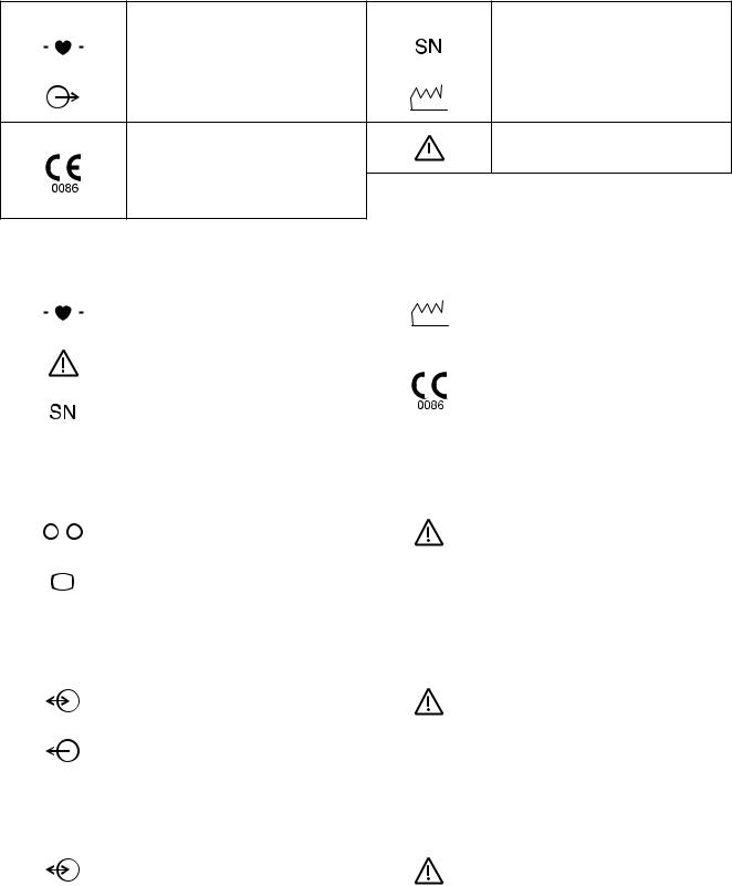
AY Series Input Unit
Symbol |
Description |
Symbol |
Description |
||||||||
|
|
|
|
|
Defibrillation-proof type CF applied |
|
|
|
|
|
Serial number |
|
|
|
|
|
|
|
|
|
|
||
|
|
|
|
|
|
|
|
|
|
||
|
|
|
|
|
part |
|
|
|
|
|
|
|
|
|
|
|
|
|
|
|
|
||
|
|
|
|
|
|
|
|
|
|
|
|
|
|
|
|
|
|
|
|
|
|
|
|
|
|
|
|
|
Output terminal |
|
|
|
|
|
Date of manufacture |
|
|
|
|
|
|
|
|
|
|
||
|
|
|
|
|
|
|
|
|
|
|
|
The CE mark is a protected conformity
mark of the European Community.  Attention, consult operator’s manual Products marked with this symbol
comply with the requirements of the Medical Device Directive 93/42/EEC.
AA-672P/AA-674P Smart Expansion Unit
Symbol |
Description |
Symbol |
Description |
||||||||||
|
|
|
|
|
|
|
Defibrillation-proof type CF applied |
|
|
|
|
|
Date of manufacture |
|
|
|
|
|
|
|
|
|
|
|
|
||
|
|
|
|
|
|
|
|
|
|
|
|
||
|
|
|
|
|
|
|
part |
|
|
|
|
|
|
|
|
|
|
|
|
|
|
|
|
|
|
||
|
|
|
|
|
|
|
|
|
|
|
|
|
|
|
|
|
|
|
|
|
|
|
|
|
|
|
|
|
|
|
|
|
|
|
|
|
|
|
|
|
|
|
|
|
|
|
|
|
Attention, consult operator’s manual |
|
|
|
|
|
The CE mark is a protected conformity |
|
|
|
|
|
|
|
|
|
|
|
|
mark of the European Community. |
|
|
|
|
|
|
|
|
|
|
|
|
|
|
|
|
|
|
|
|
|
|
|
|
|
|
|
|
Products marked with this symbol |
|
|
|
|
|
|
|
|
|
|
|
|
|
|
|
|
|
|
|
|
|
Serial number |
|
|
|
|
|
comply with the requirements of the |
|
|
|
|
|
|
|
|
|
|
|
|
||
|
|
|
|
|
|
|
|
|
|
|
|
Medical Device Directive 93/42/EEC. |
|
|
|
|
|
|
|
|
|
|
|
|
|
|
|
|
|
|
|
|
|
|
|
|
|
|
|
|
|
|
|
|
|
|
|
|
|
|
|
|
|
|
|
QI-631P Interface |
|
|
|
|
|
|
|
||||||
|
|
|
|
|
|
|
|
|
|||||
Symbol |
Description |
Symbol |
Description |
||||||||||
|
|
|
|
|
|
|
Serial interface (RS-232C socket) |
|
|
|
|
|
Attention, consult operator’s manual |
|
|
|
|
|
|
|
|
|
|
|
|
||
|
|
|
|
|
|
|
|
|
|
|
|
|
|
|
|
|
|
|
|
|
External display (RGB socket) |
|
|
|
|
|
|
|
|
|
|
|
|
|
|
|
|
|
|
|
|
|
|
|
|
|
|
|
|
|
|
|
|
|
|
QI-632P Interface |
|
|
|
|
|
|
|
||||||
|
|
|
|
||||||||||
Symbol |
Description |
Symbol |
Description |
||||||||||
|
|
|
|
|
|
|
Input/output terminal (USB socket and |
|
|
|
|
|
Attention, consult operator’s manual |
|
|
|
|
|
|
|
Multi-link socket) |
|
|
|
|
|
|
|
|
|
|
|
|
|
|
|
|
|
|
|
|
|
|
|
|
|
|
|
|
|
|
|
|
|
|
|
|
|
|
|
|
|
Output terminal (Alarm socket) |
|
|
|
|
|
|
|
|
|
|
|
|
|
|
||||||
QI-634P Interface |
|
|
|
|
|
|
|
||||||
|
|
|
|
||||||||||
Symbol |
Description |
Symbol |
Description |
||||||||||
|
|
|
|
|
|
|
Input/output terminal (USB socket and |
|
|
|
|
|
Attention, consult operator’s manual |
|
|
|
|
|
|
|
Multi-link socket) |
|
|
|
|
|
|
|
|
|
|
|
|
|
|
|
|
|
|
|
|
|
|
|
|
|
|
|
|
|
|
|
|
|
|
viii |
User’s Guide Part I BSM-6000 |
QI-671P Interface
Symbol |
Description |
Symbol |
Description |
|||||||||||
|
|
|
|
|
|
|
|
Input/output terminal (Multi-link |
|
|
|
|
|
External display (RGB socket) |
|
|
|
|
|
|
|
|
|
|
|
|
|
||
|
|
|
|
|
|
|
|
socket) |
|
|
|
|
|
|
|
|
|
|
|
|
|
|
|
|
|
|
|
|
|
|
|
|
|
|
|
|
|
|
|
|
|
|
|
|
|
|
|
|
|
|
|
|
Serial interface (RS-232C socket) |
|
|
|
|
|
Attention, consult operator’s manual |
|
|
|
|
|
|
|
|
|
|
|
|
|
||
|
|
|
|
|
|
|
|
|
|
|
|
|
|
|
|
|
|
|
|
|
|
|
Output (Alarm socket) |
|
|
|
|
|
|
|
|
|
|
|
|
|
|
|
|
|
|
|
|
|
QI-672P Interface |
|
|
|
|
|
|
|
|||||||
|
|
|
|
|
|
|
|
|
|
|
|
|
|
|
Symbol |
Description |
Symbol |
Description |
|||||||||||
|
|
|
|
|
|
|
|
Input/output terminal (USB socket and |
|
|
|
|
|
Attention, consult operator’s manual |
|
|
|
|
|
|
|
|
Multi-link socket) |
|
|
|
|
|
|
|
|
|
|
|
|
|
|
|
|
|
|
|
|
|
|
|
|
|
|
|
|
|
|
|
|
|
|
|
|
WS-671P Recorder Module |
|
|
|
|
|
|
||||||||
|
|
|
|
|
|
|
|
|
|
|
|
|
|
|
Symbol |
Description |
Symbol |
Description |
|||||||||||
|
|
|
|
|
|
|
|
Attention, consult operator’s manual |
|
|
|
|
|
The CE mark is a protected conformity |
|
|
|
|
|
|
|
|
|
|
|
|
|
mark of the European Community. |
|
|
|
|
|
|
|
|
|
|
|
|
|
|
|
|
|
|
|
|
|
|
|
|
|
|
|
|
|
|
Products marked with this symbol |
|
|
|
|
|
|
|
|
|
|
|
|
|
|
|
|
|
|
|
|
|
|
|
Serial number |
|
|
|
|
|
comply with the requirements of the |
|
|
|
|
|
|
|
|
|
|
|
|
|
||
|
|
|
|
|
|
|
|
|
|
|
|
|
Medical Device Directive 93/42/EEC. |
|
|
|
|
|
|
|
|
|
|
|
|
|
|
|
|
|
|
|
|
|
|
|
|
|
|
|
|
|
|
|
|
|
|
|
|
|
|
|
Date of manufacture |
|
|
|
|
|
|
|
|
|
|
|
|
|
|
|
|
|
|
|
|
|
|
|
|
|
|
|
|
|
|
|
|
|
|
|
|
SB-671P Battery Pack |
|
|
|
|
|
|
||||||||
|
|
|
|
|
|
|
|
|
|
|
||||
Symbol |
Description |
Symbol |
Description |
|||||||||||
|
|
|
|
|
|
|
|
Date of manufacture |
|
|
|
|
|
Recycle mark |
|
|
|
|
|
|
|
|
|
|
|
|
|
||
|
|
|
|
|
|
|
|
|
|
|
|
|
|
|
|
|
|
|
|
|
|
|
Products marked with this symbol |
|
|
|
|
|
Environmental protection use period: |
|
|
|
|
|
|
|
|
|
|
|
|
|
10 years |
|
|
|
|
|
|
|
|
|
comply with the European WEEE |
|
|
|
|
|
|
|
|
|
|
|
|
|
|
|
|
|
|
|
|
|
|
|
|
|
|
|
|
|
directive 2002/96/EEC and require |
|
|
|
|
|
The CE mark is a protected conformity |
|
|
|
|
|
|
|
|
|
|
|
|
|
||
|
|
|
|
|
|
|
|
separate waste collection. For Nihon |
|
|
|
|
|
|
|
|
|
|
|
|
|
|
|
|
|
|
|
mark of the European Community. |
|
|
|
|
|
|
|
|
|
Kohden products marked with this |
|
|
|
|
|
|
|
|
|
|
|
|
|
|
|
|
|
|
|
Products marked with this symbol |
|
|
|
|
|
|
|
|
|
symbol, contact your Nihon Kohden |
|
|
|
|
|
|
|
|
|
|
|
|
|
|
|
|
|
|
|
||
|
|
|
|
|
|
|
|
|
|
|
|
|
comply with the requirements of the |
|
|
|
|
|
|
|
|
|
representative for disposal. |
|
|
|
|
|
|
|
|
|
|
|
|
|
|
|
|
|
|
|
Medical Device Directive 93/42/EEC. |
|
|
|
|
|
|
|
|
|
|
|
|
|
|
|
|
|
|
|
|
|
|
|
|
|
|
|
|
|
||
On screen |
|
|
|
|
|
|
|
|||||||
|
|
|
|
|||||||||||
Symbol |
Description |
Symbol |
Description |
|||||||||||
|
|
|
|
|
|
|
|
Alarm silence |
|
|
|
|
|
Accessing to SD card |
|
|
|
|
|
|
|
|
|
|
|
|
|
|
|
|
|
|
|
|
|
|
|
Alarm suspended |
|
|
|
|
|
Checking SD card |
|
|
|
|
|
|
|
|
|
|
|
|
|
|
|
|
|
|
|
|
|
|
|
All alarms off or vital sign alarm limit |
|
|
|
|
|
SD card failure |
|
|
|
|
|
|
|
|
off |
|
|
|
|
|
|
|
|
|
|
|
|
|
|
|
|
|
|
|
|
|
|
|
|
|
|
|
|
|
|
|
|
|
|
|
|
|
|
|
|
|
|
|
|
Non-paced |
|
|
|
|
|
Adjust setting/Scroll data |
|
|
|
|
|
|
|
|
|
|
|
|
|
|
|
User’s Guide Part I BSM-6000 |
ix |

Symbol |
Description |
Symbol |
Description |
|
|
|
QRS/pulse sync mark |
|
Zoom in/Zoom out |
|
|
|
|
|
|
|
Respiration sync mark |
|
Left end/Right end |
|
|
|
|
|
|
|
Battery status |
@ |
Touch panel calibration |
|
|
|||
|
|
|||
|
|
|
|
|
User’s Guide Part I BSM-6000

Related Documentation
The BSM-6301A/K, BSM-6501A/K and BSM-6701A/K bedside monitors come with the following manuals in addition to the operator’s manual.
Administrator’s Guide
Describes how to install the bedside monitor. It also explains about the password protected settings on the SYSTEM SETUP window and SYSTEM CONFIGURATION screen which only an administrator can change.
User’s Guide, Part I
Gives supplemental information on the operation of the bedside monitor.
User’s Guide, Part II
Describes the features and settings of the monitoring parameters.
Service Manual
Describes information on servicing the bedside monitor. Only qualified service personnel can service the bedside monitor.
Safety Standards
The safety standard of this bedside monitor is classified as follows:
Type of protection against electrical shock: CLASS I EQUIPMENT (AC Powered)
Internally Powered EQUIPMENT (BATTERY Powered)
Degree of protection against electrical shock Degree of protection against electrical shock
Defibrillator-proof type CF applied part
AY-631P, AY-633P, AY-651P, AY-653P, AY-661P, AY-663P, AY-671P and AY-673P:
ECG, Respiration (impedance and thermistor method), IBP, Temperature, SpO2, CO2, O2, NIBP, BIS
AY-660P: ECG, Respiration (impedance method), IBP, Temperature, SpO2, CO2, NIBP AA-672P and AA-674P: Respiration (thermistor method), IBP, Temperature, SpO2, CO2, O2, BIS
CF applied part:
AY-631P, AY-633P, AY-651P, AY-653P, AY-661P, AY-663P, AY-671P, AY-673P, AA-672P and AA-674P: CO Degree of protection against harmful ingress of water: IPX0 (non-protected)
Degree of safety of application in the presence of FLAMMABLE ANAESTHETIC MIXTURE WITH AIR, OR WITH OXYGEN OR NITROUS OXIDE:
Equipment not suitable for use in the presence of FLAMMABLE ANAESTHETIC MIXTURE WITH AIR, OR WITH OXYGEN OR NITROUS OXIDE
Mode of operation: CONTINUOUS OPERATION
Safety Information
This User’s Guide only contains safety information related to operation. Full information is in the BSM-6000A/K series Bedside Monitor Operator’s Manual (code number: 0614-900685H).
User’s Guide Part I BSM-6000 |
xi |

Section 1 General 1
Introduction.......................................................................................................................................................... |
1.3 |
General...................................................................................................................................................... |
1.3 |
Applications..................................................................................................................................... |
1.4 |
Features........................................................................................................................................... |
1.4 |
Measurement Parameters, and Applicable Units............................................................................. |
1.6 |
Composition......................................................................................................................................................... |
1.8 |
Network Composition........................................................................................................................................... |
1.9 |
Panel Description............................................................................................................................................... |
1.10 |
MU-631R Main Unit................................................................................................................................. |
1.10 |
Front Panel.................................................................................................................................... |
1.10 |
Left Side Panel............................................................................................................................... |
1.11 |
Right Side Panel............................................................................................................................ |
1.11 |
Rear Panel..................................................................................................................................... |
1.12 |
MU-651R/MU-671R Main Unit................................................................................................................. |
1.13 |
Front Panel.................................................................................................................................... |
1.13 |
Left Side Panel............................................................................................................................... |
1.14 |
Right Side Panel............................................................................................................................ |
1.14 |
Rear Panel..................................................................................................................................... |
1.15 |
AY-631P/633P/651P/653P/660P/661P/663P/671P/673P Input Unit........................................................ |
1.16 |
Front Panel.................................................................................................................................... |
1.16 |
Using MULTI Sockets for CO Monitoring....................................................................................... |
1.16 |
Using the Output Signal from the ECG/BP OUT Socket................................................................ |
1.17 |
Left Side Panel............................................................................................................................... |
1.18 |
Right Side Panel............................................................................................................................ |
1.18 |
Rear Panel..................................................................................................................................... |
1.19 |
AA-672P/AA-674P Smart Expansion Unit............................................................................................... |
1.19 |
Front Panel.................................................................................................................................... |
1.19 |
Using MULTI Sockets for CO Monitoring....................................................................................... |
1.20 |
Right Side Panel............................................................................................................................ |
1.20 |
QF series Interface and IF series Communication Cable........................................................................ |
1.21 |
RY-910PA Remote Controller................................................................................................................... |
1.22 |
Basic Operating Concepts................................................................................................................................. |
1.23 |
Screen Displays....................................................................................................................................... |
1.23 |
Using Touch Screen Keys ....................................................................................................................... |
1.29 |
Keys on the Bedside Monitor................................................................................................................... |
1.30 |
Using the Remote Control........................................................................................................................ |
1.31 |
Using the Mouse...................................................................................................................................... |
1.31 |
Using the Data Acquisition Unit............................................................................................................... |
1.32 |
Using the MENU Window......................................................................................................................... |
1.33 |
Transport Function............................................................................................................................................. |
1.34 |
Overview.................................................................................................................................................. |
1.34 |
Requirements........................................................................................................................................... |
1.34 |
Necessary Settings Before Use............................................................................................................... |
1.34 |
User’s Guide Part I BSM-6000 |
1.1 |
Transported Data and Settings................................................................................................................ |
1.35 |
Sending Data to a CNS-9701 Central Monitor......................................................................................... |
1.36 |
Patient Authentication.............................................................................................................................. |
1.37 |
Preparing for Removing the Input Unit..................................................................................................... |
1.41 |
Enabling the Input Unit............................................................................................................................. |
1.42 |
When the Input Unit is Disabled.................................................................................................... |
1.42 |
Enabling the Input Unit.................................................................................................................. |
1.42 |
1.2 |
User’s Guide Part I BSM-6000 |

Introduction
1. GENERAL
1
General
The Life Scope TR BSM-6301A/K, BSM-6501A/K and BSM-6701A/K bedside monitors are for one patient. You can combine the monitor with other units and options depending on the measurement parameters and use the monitor in a wide range of sites such as the operating rooms and intensive care unit (ICU).
You can also connect this monitor to a network to communicate with a central monitor and other bedside monitors.
The BSM-6301A/K bedside monitor has a 10.4 inch TFT color display, BSM6501A/K has a 12.1 inch TFT color display, and BSM-6701A/K has a 15 inch TFT color display. All models can display 15 waveforms on the screen.
For simplicity, the suffixA/G/K will be omitted in this manual.
WARNING
Do not diagnose a patient based on only part of the monitoring data on the bedside monitor or only on the data acquired by the bedside monitor. Overall judgement must be performed by a physician who understands the features, limitations and characteristics of the bedside monitor by reading this user’s guide thoroughly and by reading the biomedical signals acquired by other instruments.
WARNING
Do not use the same monitor for more than one patient at the same time. Do not connect different sensors from different patients to the same monitor.
NOTE
•Upgrade the main unit and each optional unit to the Nihon Kohden recommended software version. Only use the specified configuration of units. If more than one BSM-6000 series bedside monitor is used in the same facility, make sure the bedside monitors have the same software version. If BSM-6000 series monitors with different software versions are used together, correct system operation cannot be guaranteed.
•Be sure to have the administrator change settings for system operation to modify purposes of system use or relocate the system, or have any changes checked by the administrator. Inappropriate changes may result in unsuitable monitoring or a missed alarm.
User’s Guide Part I BSM-6000 |
1.3 |
1. GENERAL
Applications
This system monitors biological information on a patient in an operating room, recovery room, ICU, CCU, HCU, NICU or emergency room.
Features
• Components
You can connect an input unit, smart expansion unit, interface and other
options to the main unit.
• Use of MULTI sockets
The MULTI sockets allow you to flexibly connect different parameters.
• Touch screen display
The wide angle TFT color display can display measurement values and up to 15 waveforms. You can operate the monitor by touching the screen.
• Use of remote control (Section 2)
The remote control allows operation at a distance.
• Telemetry system (Administrator’s Guide)
When the optional ZS-900P* transmitter is connected to the bedside monitor, waveform(s) and parameter data from the bedside monitor can be sent to a cardiac telemetry system or to a central monitor via a multiple patient receiver. (Available waveforms and parameter data depend on the receiving monitor. CO, O2 and anesthetic gas data cannot be transmitted.)
*ZS-900P is not available for BSM-6000A series.
•Available network connection (Administrator’s Guide)
You can connect this system via a 10/1000BASE-T LAN cable to a network to communicate with the central monitor and other devices.
•Available backup battery
When an SB-671P battery pack (option) is installed in the monitor, there is
a sudden power failure or during patient transfer, the monitor can be operated continuously on battery power.
•Home screen (Administrator’s Guide)
You can change the home screen display according to the needs of your facility.
• |
Trendgraphs and OCRG display on the home screen (Administrator’s |
|
Guide) |
|
The home screen displays trendgraphs of measured values and waveforms so |
|
you can easily identify changes in the patient condition. When a neonate is |
|
monitored, OCRG can also be displayed instead of trendgraphs. |
• |
Review information (Section 6) |
|
This system provides the capability to display review information as trends, |
|
arrhythmia recall and full disclosure waveforms. |
1.4 |
User’s Guide Part I BSM-6000 |

|
1. GENERAL |
|
• |
Thermal array recorder (Section 10) |
1 |
|
You can install a WS-671P recorder module (option) to record up to three |
|
|
waveforms and reports. |
|
• |
Multi arrhythmia analysis mode (User’s Guide Part II, Section 1) |
|
|
The multi arrhythmia analysis mode allows you to analyze arrhythmia more |
|
|
accurately. |
|
• |
ECG window (User’s Guide Part II, Section 1) |
|
|
This system displays QRS waveforms of the normal waveform as the dominant |
|
|
QRS, allowing you to check analysis accuracy. |
|
• 12 lead analysis (Section 7)
When the 10-electrode ECG is monitored, you can display standard 12 lead ECG. 12 lead interpretation is provided.
• Function keys (Administrator’s Guide)
You can register frequently used operations to function key.
• Different site setting (Administrator’s Guide)
You can set different settings for different sites (OR, ICU and NICU).
Standard components
•MU-631R, MU-651R, MU-671R main unit
•QI-631P, QI-632P, QI-634P, QI-671P, QI-672P interface
•AY-631P, AY-633P, AY-651P, AY-653P, AY-660P*, AY-661P*, AY-663P*, AY-671P, AY-673P input unit
*AY-660P, AY-661P and AY-663P input units are not available for BSM6000A series.
•AA-672P, AA-674P smart expansion unit
•WS-671P recorder module
•SB-671P battery pack
NOTE
When AY-660P input unit is used, the AA-672P or AA-674P smart expansion unit cannot be used.
When an AY-600P series input unit has a QM-600P memory unit installed, the data of the bedside monitor can be saved and sent to another bedside monitor. For details, refer to the “Transport Function” section.
User’s Guide Part I BSM-6000 |
1.5 |
1. GENERAL
Measurement Parameters, and Applicable Units
|
|
|
|
|
Applicable Units |
|
|
|
|
|
QI-632P |
|
|
Measurement Parameters |
AY series |
QI-634P |
|
|
||
QI-671P |
|
Other Units |
||||
|
|
|
Input Unit |
|
||
|
|
|
QI-672P |
|
|
|
|
|
|
|
|
|
|
|
|
|
|
Interface |
|
|
ECG |
|
OK |
– |
|
– |
|
Respiration |
|
Impedance method |
OK |
– |
|
– |
|
Thermistor method |
OK*1 |
– |
|
– |
|
|
|
|
||||
|
|
Mainstream |
OK*1 |
– |
|
– |
|
|
|
|
|
|
• AG-400R CO2 unit*3 |
CO2 |
|
|
|
|
|
• AG-920R multigas unit |
|
Sidestream |
– |
OK |
|
• GF-110PA multigas unit |
|
|
|
|
• GF-120PAmultigas/flow unit*3 |
|||
|
|
|
|
|
|
|
|
|
|
|
|
|
• GF-210R multigas unit*3 |
|
|
|
|
|
|
• GF-220R multigas/flow unit*3 |
SpO2 |
|
OK |
– |
|
– |
|
NIBP |
|
OK |
– |
|
– |
|
IBP |
|
OK*1 |
– |
|
– |
|
Temperature |
|
TEMP socket |
OK |
– |
|
– |
|
MULTI socket |
OK*1 |
– |
|
– |
|
|
|
|
||||
|
|
MULTI socket |
– |
OK |
|
• YJ-671P BISx connection cable |
BIS |
|
|
• QE-910P BIS processor/BISx |
|||
|
|
|
|
|
||
|
|
Multi-link socket |
– |
OK |
|
External instrument |
Cardiac output |
OK*1 |
OK |
|
– |
||
|
|
|
|
|
|
• AG-920R multigas unit |
|
|
|
|
|
|
• GF-110PA multigas unit |
Anesthetic gas*2 |
– |
OK |
|
• GF-120PAmultigas/flow unit*3 |
||
|
|
|
|
|
|
• GF-210R multigas unit*3 |
|
|
|
|
|
|
• GF-220R multigas/flow unit*3 |
|
|
|
|
|
|
• AG-920R multigas unit |
|
|
|
|
|
|
• GF-110PA multigas unit |
O2 |
|
OK*1 |
– |
|
• GF-120PAmultigas/flow unit*3 |
|
|
|
|
|
|
|
• GF-210R multigas unit*3 |
|
|
|
|
|
|
• GF-220R multigas/flow unit*3 |
Ventilation |
|
– |
OK |
|
External instrument |
|
TOF |
|
– |
OK |
|
External instrument |
|
CCO |
|
– |
OK |
|
External instrument |
|
FLOW/Paw |
|
– |
OK |
|
• GF-120PAmultigas/flow unit*3 |
|
|
|
• GF-220R multigas/flow unit*3 |
||||
|
|
|
|
|
|
|
EEG |
|
– |
OK |
|
AE-918P neuro unit*3 |
|
tcPO2/tcPCO2 |
|
– |
OK |
|
External instrument |
|
*1 These parameters cannot be measured by the MULTI sockets on the AY-660P input unit, but can be measured by the MULTI sockets on the JA-694PA data acquisition unit.
*2 RR, CO2 (Sidestream), O2, N2O, AGENT, MAC and FLOW/Paw can be measured. *3 These units are not available for BSM-6000A series.
1.6 |
User’s Guide Part I BSM-6000 |

|
|
|
|
|
|
|
|
|
|
|
|
1. GENERAL |
|||
|
|
Differences Between the Input Unit Models |
|
|
|
1 |
|||||||||
|
|
|
|
|
|
|
|
|
|
|
|
|
|
|
|
|
Input Unit Model |
|
AY-631P |
AY-633P |
AY-651P |
AY-653P |
AY-660P*1 |
AY-661P*1 |
|
AY-663P*1 |
|
||||
|
|
AY-671P |
|
AY-673P |
|
||||||||||
|
|
|
|
|
|
|
|
|
|
|
|
|
|
||
No. of MULTI sockets |
|
1 |
|
3 |
|
1 |
|
3 |
1 |
|
1 |
|
3 |
|
|
Available parameters |
|
RESP (Thermistor), CO2, SpO2, IBP, |
|
|
RESP (Thermistor), |
|
|||||||||
|
CO2, IBP |
|
CO2, SpO2, IBP, TEMP, |
|
|||||||||||
using MULTI sockets |
|
TEMP, BIS, CO, O2 |
|
|
|
|
|
||||||||
|
|
|
|
|
|
BIS, CO, O2 |
|
|
|||||||
|
|
|
|
|
|
|
|
|
|
|
|
|
|
||
No. of TEMP sockets |
|
|
2 |
|
|
|
1 |
|
2 |
|
|||||
ECG measurement |
|
|
|
Yes |
|
|
|
No |
|
Yes |
|
||||
using 10 electrodes |
|
|
|
|
|
|
|
|
|||||||
|
|
|
|
|
|
|
|
|
|
|
|
|
|
||
12 lead analysis |
|
|
|
Yes |
|
|
|
No |
|
Yes |
|
||||
SpO2 probe |
|
|
Masimo |
|
|
Nellcor |
|
Nihon Kohden |
|
||||||
Dual SpO2 |
|
|
Yes*2 |
|
|
Yes*3 |
Yes*4 |
|
Yes*5 |
|
|||||
NIBP PWTT |
|
|
|
No |
|
|
|
|
|
Yes |
|
|
|||
measurement |
|
|
|
|
|
|
|
|
|
|
|||||
|
|
|
|
|
|
|
|
|
|
|
|
|
|
||
Smart expansion unit |
|
|
|
|
|
|
|
|
|
|
|
|
|
|
|
Analog ECG |
|
|
|
Yes |
|
|
|
No |
|
Yes |
|
||||
Analog BP |
|
|
|
|
|
|
|
|
|||||||
|
|
|
|
|
|
|
|
|
|
|
|
|
|
||
HT output |
|
|
|
|
|
|
|
|
|
|
|
|
|
|
|
*1 |
AY-660P, AY-661P and AY-663P input units are not available for BSM-6000A series. |
|
|
||||||||||||
*2 |
IF-925P communication cable is required. |
|
|
|
|
|
|
|
|
|
|||||
*3 |
IF-919P communication cable is required. |
|
|
|
|
|
|
|
|
|
|||||
*4 |
Dual SpO2 is available when the MULTI socket on the JA-694PA data acquisition unit is used. |
||||||||||||||
*5 |
JL-500P1 or JL-500P2 SpO2 adapter is required. |
|
|
|
|
|
|
|
|
||||||
User’s Guide Part I BSM-6000 |
1.7 |
Loading...