


 Loading...
Operator’s Manual
Bedside Monitor
BSM-6301/BSM-6501/BSM-6701
BSM-6000 series
BSM-6301A
BSM-6301K
BSM-6501A
BSM-6501K
BSM-6701A
BSM-6701K
0614-900685H

If you have any comments or suggestions on this manual, please contact us at: www.nihonkohden.com
Copyright Notice
The entire contents of this manual are copyrighted by Nihon Kohden. All rights are reserved. No part of this document may be reproduced, stored, or transmitted in any form or by any means (electronic, mechanical, photocopied, recorded, or otherwise) without the prior written permission of Nihon Kohden.
Trademark
The mark printed on the SD card that is used in this instrument is a trademark. The company name and model name are trademarks and registered trademarks of each company.

Contents
About this Manual....................................................... |
1 |
Related Documentation............................................... |
1 |
Intended Purpose........................................................ |
2 |
Precautions................................................................. |
4 |
General Handling Precautions............................... |
4 |
EMC Related Caution............................................ |
4 |
Other Caution......................................................... |
6 |
Responsibility of the Manufacturer.............................. |
6 |
Conventions Used in this Manual and Instrument....... |
7 |
Warnings, Cautions and Notes.............................. |
7 |
Text Conventions in this Manual............................. |
7 |
Explanations of the Symbols in this Manual and |
|
Instrument.............................................................. |
8 |
General Safety Information....................................... |
11 |
Panel Description...................................................... |
13 |
MU-631R Main Unit............................................. |
13 |
MU-651R/MU-671R Main Unit............................. |
15 |
AY-631P/AY-633P/AY-651P/AY-653P/AY-660P/ |
|
AY-661P/AY-663P/AY-671P/AY-673P Input Unit.... |
17 |
AA-672P/AA-674P Smart Expansion Unit........... |
19 |
Installation................................................................. |
21 |
General................................................................ |
21 |
Grounding the Monitor.................................... |
22 |
Environment for External Instruments............. |
22 |
Warnings and Cautions for Connecting the |
|
Monitor to a Network....................................... |
23 |
Inserting and Removing the Battery Packs.......... |
24 |
Inserting the Battery Pack............................... |
24 |
Removing the Battery Pack............................. |
25 |
Inserting and Removing the Input Unit................. |
26 |
Inserting the Input Unit.................................... |
26 |
Removing the Input Unit................................. |
26 |
Loading Recording Paper.................................... |
27 |
Turning the Monitor On or Off.................................... |
28 |
Turning the Monitor On........................................ |
28 |
Check Before Turning On the Power............... |
28 |
Check After Turning On the Power and |
|
During Monitoring........................................... |
29 |
Power and Battery Status Indications............. |
30 |
Battery Pack Handling and Operation............. |
31 |
Charging the Battery Pack.............................. |
33 |
Monitor Status on Power Interruption................... |
34 |
Turning the Monitor Off........................................ |
34 |
Check After or Before Turning the Power Off.. 34 |
|
Basic Operation......................................................... |
35 |
Using the Hard Keys on the Bedside Monitor |
|
Operator’s Manual BSM-6000 |
|
and Touch Screen................................................ |
35 |
Using the Remote Control.................................... |
35 |
Using the Mouse.................................................. |
35 |
Home Screen Description......................................... |
36 |
Settings for the Home Screen.............................. |
37 |
Trendgraph on the Home Screen (Current |
|
Trendgraph).......................................................... |
38 |
OCRG............................................................. |
38 |
Freezing Waveforms............................................. |
38 |
Using Sleep Mode................................................ |
38 |
MENU Window Description....................................... |
39 |
Changing Settings..................................................... |
40 |
Administrator Settings.......................................... |
40 |
Changing Parameter Settings and Other |
|
Settings................................................................ |
40 |
Changing Settings........................................... |
40 |
Changing Settings on the VOLUME |
|
Window........................................................... |
41 |
Admitting a Patient/Discharging a Patient (Deleting |
|
Data)......................................................................... |
42 |
Admitting a Patient............................................... |
43 |
Discharging a Patient (Deleting Data).................. |
44 |
Transport................................................................... |
45 |
Warnings and Cautions for Transport.............. |
45 |
Alarms....................................................................... |
47 |
Alarm Types and Levels....................................... |
47 |
Alarm Control Marks............................................ |
48 |
Flow of Alarm Function........................................ |
49 |
Silencing/Suspending Alarms.............................. |
50 |
Silencing Alarms............................................. |
50 |
Suspending Alarms......................................... |
50 |
Canceling Technical Alarms................................. |
53 |
Alarm Sound Volume........................................... |
53 |
Alarm Recording.................................................. |
53 |
Alarm Setting....................................................... |
53 |
Changing Vital Sign Upper/Lower Alarm |
|
Limits............................................................... |
55 |
Changing the Arrhythmia Alarm Settings........ |
57 |
Interbed Alarm..................................................... |
58 |
Review Windows....................................................... |
59 |
General................................................................ |
59 |
Event Bar........................................................ |
60 |
TREND Window................................................... |
61 |
GRAPH 1, GRAPH 2, GRAPH 3 Page........... |
61 |
TABLE 1, TABLE 2, TABLE 3 Page................. |
62 |
NIBP TREND Page......................................... |
63 |
|
C. |

HEMO Page.................................................... |
64 |
Registering the Acquired Data to the |
|
Hemodynamics Table Window........................ |
64 |
LUNG TREND Page........................................ |
65 |
RECALL Window................................................. |
66 |
ARRHYTH HISTORY Page............................. |
66 |
ALARM HISTORY Window.................................. |
67 |
ALARM HISTORY Page.................................. |
67 |
FULL DISC Window............................................. |
68 |
FULL DISC Page............................................ |
68 |
ST Window........................................................... |
70 |
ST INTERVAL Page........................................ |
70 |
OCRG Window..................................................... |
71 |
12 LEAD/12 LEAD ANALYSIS Windows................... |
72 |
General................................................................ |
72 |
Performing 12 Lead ECG Interpretation......... |
72 |
12 LEAD Window................................................. |
74 |
Viewing the 12 Lead Analysis Result.............. |
74 |
DRUG/LUNG FUNCTION Windows.......................... |
76 |
DRUG Window..................................................... |
76 |
LUNG FUNCTION Window.................................. |
78 |
Recording.................................................................. |
80 |
Recording Modes................................................. |
80 |
When More than One Recording Modes is |
|
Triggered......................................................... |
80 |
Changing Recording Settings.............................. |
80 |
Selecting Recording Waveforms..................... |
81 |
Changing Recording Speed............................ |
81 |
Selecting Recording Interval for Periodic |
|
Recording........................................................ |
81 |
Turning Alarm Recording On or Off................ |
81 |
INTERBED Window.................................................. |
82 |
Registering/Removing Interbed Beds.................. |
82 |
Displaying the Interbed Bed Data........................ |
83 |
Interbed Alarm..................................................... |
84 |
Settings Related to Interbed Alarm................. |
84 |
Monitoring Parameters.............................................. |
85 |
ECG..................................................................... |
85 |
Preparation..................................................... |
85 |
Monitoring Arrhythmia..................................... |
88 |
Changing ECG Settings.................................. |
90 |
Respiration........................................................... |
97 |
Preparation..................................................... |
97 |
Changing Respiration Settings....................... |
98 |
CO2 .................................................................... |
100 |
Preparation................................................... |
101 |
Changing CO2 Settings................................. |
104 |
Inspection of Measuring Accuracy................ |
106 |
SpO2 with Nihon Kohden Probes (AY-660P/ |
|
AY-661P/AY-663P/AY-671P/AY-673P)................. |
107 |
Silencing SpO2 Alarm.................................... |
108 |
Preparation................................................... |
108 |
Changing SpO2 Settings............................... |
110 |
SpO2 with Nellcor Probes (AY-651P/AY-653P)... |
114 |
Silencing SpO2 Alarm.................................... |
115 |
Preparation................................................... |
115 |
Changing SpO2 Settings............................... |
117 |
SpO2 with Masimo Probes (AY-631P/AY-633P).. |
120 |
Silencing SpO2 Alarm.................................... |
121 |
Preparation................................................... |
121 |
Changing SpO2 Settings............................... |
124 |
NIBP................................................................... |
128 |
Preparation................................................... |
128 |
Changing NIBP Settings............................... |
130 |
Starting and Stopping NIBP Measurement... |
132 |
IBP..................................................................... |
136 |
Preparation................................................... |
136 |
Connecting Cables to the Unit...................... |
136 |
Assembling the Transducer........................... |
137 |
Adjusting Zero Balance................................. |
138 |
The CHECK ZERO Page.............................. |
139 |
Changing IBP Settings.................................. |
139 |
Temperature....................................................... |
144 |
Preparation................................................... |
144 |
Using the Insulation Pad............................... |
145 |
Changing Temperature Settings.................... |
145 |
BIS..................................................................... |
147 |
Preparation................................................... |
147 |
Changing the BIS Settings............................ |
150 |
Cardiac Output................................................... |
153 |
Preparation................................................... |
153 |
Measuring the Pulmonary Capillary Wedge |
|
Pressure........................................................ |
154 |
Measuring Cardiac Output............................ |
155 |
Deleting the Data from the CO Table ........... |
158 |
Adding the Acquired Data to the HEMO |
|
Page of the TREND Window......................... |
159 |
GAS................................................................... |
160 |
Preparation................................................... |
160 |
Changing Gas Settings................................. |
160 |
Inspection of Measuring Accuracy................ |
164 |
O2 ....................................................................... |
165 |
Preparation................................................... |
165 |
Changing O2 Settings.................................... |
166 |
Other Parameters............................................... |
167 |
Screen Messages................................................... |
169 |
Troubleshooting....................................................... |
185 |
Monitoring.......................................................... |
185 |
C. |
Operator’s Manual BSM-6000 |

Network.............................................................. |
185 |
Transport............................................................ |
186 |
Remote Control.................................................. |
187 |
Recording........................................................... |
187 |
Printing............................................................... |
187 |
ECG................................................................... |
188 |
Respiration......................................................... |
189 |
Impedance Method....................................... |
189 |
Thermistor Method........................................ |
189 |
CO2 .................................................................... |
190 |
Mainstream Method...................................... |
190 |
Sidestream Method....................................... |
190 |
When Using Microcap® Monitor.................... |
191 |
SpO2 .................................................................. |
191 |
When Using Nellcor/Masimo Pulse |
|
Oximeter....................................................... |
192 |
NIBP................................................................... |
192 |
IBP..................................................................... |
193 |
Temperature....................................................... |
193 |
BIS..................................................................... |
193 |
When Using BIS Processor/BISx.................. |
193 |
When Using BIS Monitor............................... |
193 |
Cardiac Output................................................... |
194 |
GAS................................................................... |
194 |
When Using AG-920R Multigas Unit............. |
194 |
When Using GF-110PA Multigas Unit or |
|
GF-120PA Multigas/Flow Unit....................... |
195 |
When Using GF-210R Multigas Unit or |
|
GF-220R Multigas/Flow Unit......................... |
196 |
When Using Dräger Medical Primus/ |
|
Fabius® Anesthesia Workstation................... |
197 |
O2 ...................................................................... |
197 |
Ventilation........................................................... |
197 |
TOF.................................................................... |
198 |
CCO................................................................... |
198 |
When Using Vigilance Monitor...................... |
198 |
When Using PiCCO Monitor......................... |
198 |
CCO/SvO2 ......................................................... |
199 |
FLOW/Paw......................................................... |
199 |
When Using GF-110PA Multigas/Flow Unit.. 199 |
|
When Using GF-220R Multigas/Flow Unit.... |
199 |
EEG................................................................... |
200 |
tcPO2/tcPCO2 .................................................... |
201 |
Transmitter......................................................... |
201 |
12 Lead ECG..................................................... |
201 |
Maintenance............................................................ |
202 |
MU-631R, MU-651R and MU-671R Main Unit... |
202 |
Cleaning and Disinfecting the Main Unit....... |
202 |
Cleaning the Touch Screen........................... |
203 |
Disposing of the Main Unit............................ |
204 |
WS-671P Recorder Module............................... |
204 |
Cleaning the Thermal Head.......................... |
204 |
Cleaning the Sensors.................................... |
204 |
Disposing of the Recorder Module................ |
204 |
AY Series Input Unit and AA-672P/AA-674P |
|
Smart Expansion Unit........................................ |
205 |
Cleaning and Disinfecting the Units.............. |
205 |
Disposing of the Units................................... |
205 |
SB-671P Battery Pack....................................... |
205 |
Battery Lifetime............................................. |
205 |
Replacing the Batteries................................. |
205 |
Disposing of Batteries................................... |
205 |
RY-910P Remote Controller............................... |
205 |
Cleaning and Disinfecting the Remote |
|
Controller...................................................... |
205 |
Disposing of the Remote Controller.............. |
205 |
Replacing the Batteries................................. |
205 |
Disposing of Batteries................................... |
205 |
QF series Interface and IF series |
|
Communication Cable........................................ |
205 |
Cleaning and Disinfecting the Interface and |
|
Communication Cable................................... |
205 |
Disposing of the Interface and |
|
Communication Cable................................... |
205 |
Leads, Cables and Cords................................... |
206 |
Cleaning the Leads, Cables and Cords........ |
206 |
Disinfecting the Leads, Cables and Cords.... |
206 |
Disposing of Leads, Cables and Cords......... |
206 |
Electrodes, Probes, Cuffs, Thermistors, |
|
Transducers, Catheters and Other |
|
Consumables..................................................... |
206 |
Yearly Inspection................................................ |
206 |
Safety Information for Maintenance on |
|
Optional Units.................................................... |
207 |
AG-920R, GF-110PA or GF-210R Multigas |
|
Unit and GF-120PA or GF-220R Multigas/ |
|
Flow Unit....................................................... |
207 |
AG-400R CO2 Unit........................................ |
207 |
AE-918P Neuro Unit..................................... |
208 |
Specifications.......................................................... |
209 |
Measuring Parameters.................................. |
209 |
Influence on Measuring Accuracy by |
|
Electrosurgery/Defibrillation/Electrostatic |
|
Discharge...................................................... |
209 |
Display.......................................................... |
209 |
Alarm............................................................ |
210 |
Alarm Delay Time.......................................... |
211 |
ECG ............................................................. |
211 |
Operator’s Manual BSM-6000 |
C. |

Respiration (Transthoracic impedance |
|
pneumography)............................................. |
214 |
SpO2 ............................................................. |
214 |
Non Invasive Blood Pressure, NIBP............. |
217 |
Multi Socket................................................... |
218 |
Invasive Blood Pressure, IBP........................ |
218 |
Temperature.................................................. |
219 |
Carbon Dioxide, CO2 (Mainstream |
|
method) ........................................................ |
219 |
Inspired Oxygen Fractional Concentration, |
|
O2 .................................................................. |
220 |
Cardiac Output, CO...................................... |
220 |
Respiration (Thermistor method).................. |
221 |
Bispectral Index, BIS..................................... |
221 |
ECG/BP Output............................................. |
221 |
RGB Socket (when QI-631P or QI-671P is |
|
connected).................................................... |
222 |
RS-232C Socket (when QI-631P or |
|
QI-671P is connected).................................. |
222 |
Alarm Socket (when QI-632P or QI-671P |
|
is connected)................................................. |
222 |
When WS-671P Recorder Module is |
|
Connected..................................................... |
222 |
When ZS-900P Transmitter is Connected..... |
223 |
Gas............................................................... |
223 |
Carbon Dioxide, CO2 (Sidestream method).. |
226 |
FLOW/Paw.................................................... |
226 |
EEG.............................................................. |
227 |
Battery (SB-671P Battery Pack)................... |
228 |
Power Requirement...................................... |
228 |
Clock Accuracy............................................. |
228 |
Environment.................................................. |
228 |
Mechanical Strength..................................... |
229 |
Electromagnetic Compatibility....................... |
229 |
Safety Standard............................................ |
229 |
Dimensions and Weight (approximate)......... |
230 |
Electromagnetic Emissions........................... |
231 |
Electromagnetic Immunity............................. |
232 |
Recommended Separation Distances |
|
between Portable and Mobile RF |
|
Communications Equipment......................... |
234 |
System Composition for EMC Test................ |
235 |
Factory Default Settings.......................................... |
236 |
Event Bar........................................................... |
236 |
TREND Window................................................. |
237 |
RECALL Window............................................... |
240 |
FULL DISC Window........................................... |
240 |
ST Window......................................................... |
240 |
OCRG Window................................................... |
241 |
C. |
|
ADMIT Window.................................................. |
241 |
ALARM LIMITS Window.................................... |
242 |
Vital Signs Alarms......................................... |
242 |
Arrhythmia Alarms........................................ |
245 |
DATE Window.................................................... |
245 |
VOLUME Window.............................................. |
246 |
DISPLAY Window............................................... |
246 |
RECORD Window.............................................. |
246 |
ECG Window...................................................... |
247 |
RESP/CO2 Window............................................ |
248 |
SpO2 Window..................................................... |
248 |
NIBP Window..................................................... |
249 |
PRESS Window................................................. |
250 |
TEMP Window................................................... |
251 |
BIS Window........................................................ |
251 |
CO Window........................................................ |
251 |
GAS Window...................................................... |
252 |
O2 Window.......................................................... |
252 |
VENT Window.................................................... |
252 |
CCO Window..................................................... |
253 |
FLOW/Paw Window........................................... |
253 |
EEG Window...................................................... |
254 |
12 LEAD ANALYSIS Window............................. |
255 |
DRUG Window................................................... |
255 |
LUNG FUNCTION Window................................ |
257 |
INTERBED Window........................................... |
257 |
Standard Accessories............................................. |
258 |
MU-631RA/MU-651RA/MU-671RA Main Unit.... |
258 |
MU-631RK/MU-651RK/MU-671RK Main Unit.... |
258 |
Options/Consumables............................................. |
259 |
Accessory Set.................................................... |
259 |
MU-631RA/MU-651RA/MU-671RA Main Unit.... |
260 |
MU-631RK/MU-651RK/MU-671RK Main Unit.... |
260 |
WS-671P Recorder Module............................... |
261 |
Units and Modules............................................. |
261 |
Network.............................................................. |
261 |
Interfaces for Connecting External |
|
Instruments........................................................ |
262 |
Cart and Attaching Parts.................................... |
263 |
For ECG and Respiration (Impedance Method) |
|
Monitoring.......................................................... |
263 |
For Respiration Monitoring (Thermistor |
|
Method).............................................................. |
264 |
For CO2 Monitoring (Mainstream Method)......... |
264 |
For SpO2 Monitoring........................................... |
265 |
For NIBP Monitoring........................................... |
266 |
For IBP Monitoring............................................. |
267 |
For Temperature Monitoring............................... |
268 |
For BIS Monitoring (Using the BIS Processor/ |
|
BISx).................................................................. |
268 |
Operator’s Manual BSM-6000 |
|

For CO Monitoring.............................................. |
268 |
For O2 Monitoring............................................... |
269 |
For CO2 Sidestream Monitoring......................... |
269 |
For BIS Monitoring (Using the BIS Monitor)....... |
269 |
For Anesthetic Agent Monitoring........................ |
269 |
For FLOW/Paw Monitoring................................. |
269 |
For EEG Monitoring........................................... |
269 |
General Requirements for Connecting Medical |
|
Electrical Systems...................................................... |
270 |
Operator’s Manual BSM-6000 |
C. |

About this Manual
This Operator’s Manual describes the most common features and functions of the BSM-6301A/K, BSM6501A/K and BSM-6701A/K bedside monitors.
Related Documentation
The BSM-6301A/K, BSM-6501A/K and BSM-6701A/K Bedside Monitors come with the following manuals in addition to the Operator’s Manual.
Administrator’s Guide
Describes how to install the bedside monitor. It also explains about the password protected settings on the SYSTEM SETUP window and SYSTEM CONFIGURATION screen which only an administrator can change.
User’s Guide, Part I
Gives supplemental information on the operation of the bedside monitor.
User’s Guide, Part II
Describes the features and settings of the monitoring parameters.
Service Manual
Describes information on servicing the bedside monitor. Only qualified service personnel can service the bedside monitor.
Operator’s Manual BSM-6000 |
1 |

Intended Purpose
The Life Scope TR BSM-6301A/K, BSM-6501A/K and BSM-6701A/K bedside monitors are for one patient. The BSM-6301A/K bedside monitors have a 10.4 inch TFT color display, BSM-6501A/K have a 12.1 inch TFT color display, and BSM-6701A/K have a 15 inch TFT color display. All the monitors can display 15 waveforms on the screen.
The bedside monitors are to be installed near the patient. With the basic configuration of the system, ECG, respiration in impedance or thermistor method, SpO2, NIBP, IBP, temperature, CO2 and O2 of all hospital patients can be monitored and alarms are generated.* The monitor is designed so the operator can directly touch the screen from the operator position. The basic configuration of the system is the following units. This manual is based on this configuration.
* Essential performance in EMC standard.
WARNING
Do not use the same monitor for more than one patient at the same time. Do not connect different sensors from different patients to the same monitor.
WARNING
Do not diagnose a patient based only on data acquired by the bedside monitor. Overall judgement must be performed by a physician who understands the features, limitations and characteristics of the bedside monitor and by reading the biomedical signals acquired by other instruments.
•MU-631RA/RK, MU-651RA/RK, MU-671RA/RK main unit
•QI-631P, QI-632P, QI-634P, QI-671P, QI-672P interface
•AY series input unit
Input Unit Model |
AY-631P |
AY-633P |
AY-651P |
AY-653P |
AY-660P*1 |
AY-661P*1 |
|
AY-663P*1 |
||||
AY-671P |
|
AY-673P |
||||||||||
|
|
|
|
|
|
|
|
|
|
|
||
No. of MULTI sockets |
1 |
|
3 |
|
1 |
|
3 |
1 |
|
1 |
|
3 |
Available parameters |
RESP (Thermistor), CO2, SpO2, IBP, |
|
|
RESP (Thermistor), |
||||||||
CO2, IBP |
|
CO2, SpO2, IBP, TEMP, |
||||||||||
using MULTI sockets |
TEMP, BIS, CO, O2 |
|
|
|
|
|||||||
|
|
|
|
|
BIS, CO, O2 |
|
||||||
|
|
|
|
|
|
|
|
|
|
|
||
No. of TEMP sockets |
|
|
2 |
|
|
|
1 |
|
2 |
|||
ECG measurement |
|
|
Yes |
|
|
|
No |
|
Yes |
|||
using 10 electrodes |
|
|
|
|
|
|
||||||
|
|
|
|
|
|
|
|
|
|
|
|
|
12 lead analysis |
|
|
Yes |
|
|
|
No |
|
Yes |
|||
SpO2 probe |
Masimo |
|
|
|
Nellcor |
|
Nihon Kohden |
|||||
Dual SpO2 |
Yes*2 |
|
|
|
Yes*3 |
Yes*4 |
|
Yes*5 |
||||
NIBP PWTT |
|
|
No |
|
|
|
|
|
Yes |
|
||
measurement |
|
|
|
|
|
|
|
|
||||
|
|
|
|
|
|
|
|
|
|
|
|
|
Smart expansion unit |
|
|
|
|
|
|
|
|
|
|
|
|
Analog ECG |
|
|
Yes |
|
|
|
No |
|
Yes |
|||
Analog BP |
|
|
|
|
|
|
||||||
|
|
|
|
|
|
|
|
|
|
|
|
|
HT output |
|
|
|
|
|
|
|
|
|
|
|
|
*1 AY-660P, AY-661P and AY-663P input units are not available for BSM-6000A series. |
|
|
|
|
||||||||
*2 IF-925P communication cable is required. |
|
|
|
|
|
|
|
|
|
|
||
*3 IF-919P communication cable is required. |
|
|
|
|
|
|
|
|
|
|
||
*4 Dual SpO2 is available when the MULTI socket on the JA-694PA data acquisition unit is used. |
|
|
|
|||||||||
*5 JL-500P1 or JL-500P2 SpO2 adapter is required. |
|
|
|
|
|
|
|
|
||||
• AA-672P/AA-674P smart expansion unit
• WS-671P recorder module
• SB-671P battery pack
Operator’s Manual BSM-6000
For simplicity, the model number suffixA/G/K is omitted in this manual.
NOTE:
•This monitor must be used by qualified medical personnel with a full knowledge of operating this monitor.
•Upgrade the main unit and each optional unit to the Nihon Kohden recommended software version. Only use the specified configuration of units. If more than one BSM-6000 series bedside monitor is used in the same facility, make sure the bedside monitors have the same software version. If BSM-6000 series monitors with different software versions are used together, correct system operation cannot be guaranteed.
•Only use Nihon Kohden parts and accessories to assure maximum performance from your instrument.
Operator’s Manual BSM-6000 |
3 |
Precautions
General Handling Precautions
•This device is intended for use only by qualified medical personnel.
•Only use Nihon Kohden approved products with this device. Use of non-approved products or in a non-approved manner may affect the performance specifications of the device. This includes, but is not limited to, batteries, recording paper, extension cables, electrode leads, input units and AC power.
•This device must receive expert, professional attention for maintenance and repairs. When the device is not functioning properly, it should be clearly marked to avoid operation while it is out of order.
•This device must not be altered or modified in any way.
EMC Related Caution
This equipment and/or system complies with IEC 60601-1-2 International Standard for electromagnetic compatibility for medical electrical equipment and/or system. However, an electromagnetic environment that exceeds the limits or levels stipulated in IEC 60601-1-2, can cause harmful interference to the equipment and/or system or cause the equipment and/or system to fail to perform its intended function or degrade its intended performance. Therefore, during the operation of the equipment and/or system, if there is any undesired deviation from its intended operational performance, you must avoid, identify and resolve the adverse electromagnetic effect before continuing to use the equipment and/or system.
The following describes some common interference sources and remedial actions:
1.Strong electromagnetic interference from a nearby emitter source such as an authorized radio station or cellular phone:
Install the equipment and/or system at another location. Keep the emitter source such as cellular phone away from the equipment and/or system, or turn off the cellular phone.
2.Radio-frequency interference from other equipment through the AC power supply of the equipment and/or system:
Identify the cause of this interference and if possible remove this interference source. If this is not possible, use a different power supply.
3.Effect of direct or indirect electrostatic discharge:
Make sure all users and patients in contact with the equipment and/or system are free from direct or indirect electrostatic energy before using it. A humid room can help lessen this problem.
4.Electromagnetic interference with any radio wave receiver such as radio or television: If the equipment and/or system interferes with any radio wave receiver, locate the equipment and/or system as far as possible from the radio wave receiver.
5.Interference of lightning:
When lightning occurs near the location where the equipment and/or system is installed, it may induce an excessive voltage in the equipment and/or system. In such a case, disconnect the AC power cord from the equipment and/or system and operate
Operator’s Manual BSM-6000
the equipment and/or system by battery power, or use an uninterruptible power supply.
6.Use with other equipment:
When the equipment and/or system is adjacent to or stacked with other equipment, the equipment and/or system may affect the other equipment. Before use, check that the equipment and/or system operates normally with the other equipment.
7.Use of unspecified accessory, transducer and/or cable:
When an unspecified accessory, transducer and/or cable is connected to this equipment and/or system, it may cause increased electromagnetic emission or decreased electromagnetic immunity. The specified configuration of this
equipment and/or system complies with the electromagnetic requirements with the specified configuration. Only use this equipment and/or system with the specified configuration.
8.Use of unspecified configuration:
When the equipment and/or system is used with the unspecified system configuration different than the configuration of EMC testing, it may cause increased electromagnetic emission or decreased electromagnetic immunity. Only use this equipment and/or system with the specified configuration.
9.Measurement with excessive sensitivity:
The equipment and/or system is designed to measure bioelectrical signals with a specified sensitivity. If the equipment and/or system is used with excessive sensitivity, artifact may appear by electromagnetic interference and this may cause mis-diagnosis. When unexpected artifact appears, inspect the surrounding electromagnetic conditions and remove this artifact source.
If the above suggested remedial actions do not solve the problem, consult your Nihon Kohden representative for additional suggestions.
The CE mark is a protected conformity mark of the European Community. Products with the CE mark comply with the requirements of the Medical Device Directive 93/42/EEC.
BSM-6301 and BSM-6501 (JA-690PA/JA-694PA data acquisition unit, QE-910P BIS processor and QI-320PA wireless LAN station are not connected) comply with International Standard IEC 60601-1-2: 2001 and Amendment 1: 2004 which requires CISPR11, Group 1, Class B. Class B EQUIPMENT is equipment suitable for use in domestic establishments and in establishments directly connected to a low voltage power supply network which supplies buildings used for domestic purposes.
BSM-6301, BSM-6501 (JA-690PA/JA-694PA data acquisition unit, QE-910P BIS processor and QI-320PA wireless LAN station are connected) and BSM-6701 comply with International Standard IEC 60601-1-2: 2001 and Amendment 1: 2004 which requires CISPR11, Group 1, Class A. Class A EQUIPMENT is equipment suitable for use in industrial or light industrial establishments and commercial environment.
BSM-6301 and BSM-6501 (when QE-910P and ZS-900P are connected) are CLASS A
Operator’s Manual BSM-6000 |
5 |

equipment if the equipment complies with IEC 60601-1-2: 2001 36 201.1.5 in the countries which do not have national wireless rule.
In IEC 60601-1-2 Medical Electronic Equipment, Part 1: General Requirements for Safety, 2. Collateral Standard: Electromagnetic compatibility-Requirements and test. Section 36. 202. 2 Radiated radio-frequency electromagnetic fields, PATIENT COUPLED EQUIPMENT and/or SYSTEMS applicable IMMUNITY test methods are under consideration at SC62A/ WG13. The 3 V/m IMMUNITY level may be inappropriate especially when measuring SpO2 because physiological signals can be much smaller than those induced by a 3 V/m electromagnetic field.
When measuring SpO2, various interference may produce false waveforms which look like pulse waveforms. SpO2 value and pulse rate may be measured from these false waveforms, causing the alarm to function improperly.
When installing the monitor, avoid locations where the monitor may receive strong electromagnetic interference such as radio or TV stations, cellular phone or mobile twoway radios.
Other Caution
United States law restricts this product to sale by or on the order of a physician.
Responsibility of the Manufacturer
Nihon Kohden Corporation (NKC) shall warrant its products against all defects in materials and workmanship for one year from the date of delivery. However, consumable materials such as recording paper, ink, stylus and battery are excluded from the warranty.
NKC or its authorized agents will repair or replace any products which prove to be defective during the warranty period, provided these products are used as prescribed by the operating instructions given in the user’s guide, operator’s and service manuals.
This warranty does not apply to products that have been modified, disassembled, reinstalled or repaired without Nihon Kohden approval or which have been subjected to neglect or accident, damage due to accident, fire, lightning, vandalism, water or other casualty, improper installation or application, or on which the original identification marks have been removed.
Operator’s Manual BSM-6000

Conventions Used in this Manual and Instrument
Warnings, Cautions and Notes
Warnings, cautions and notes are used in this manual to alert or signal the reader to specific information.
WARNING
A warning alerts the user to possible injury or death associated with the use or misuse of the instrument.
CAUTION
A caution alerts the user to possible injury or problems with the instrument associated with its use or misuse such as instrument malfunction, instrument failure, damage to the instrument, or damage to other property.
NOTE: A note provides specific information, in the form of recommendations, prerequirements, alternative methods or supplemental information.
Text Conventions in this Manual
•Names of hard keys on the bedside monitor are enclosed in square brackets: [Menu]
•Messages that are displayed on the screen are enclosed in quotation marks: “CHECK ELECTRODES”
•Names of items that are displayed on the screen are enclosed in angle brackets: <SENSITIVITY>
Operator’s Manual BSM-6000 |
7 |
Explanations of the Symbols in this Manual and Instrument
MU-631R/MU-651R/MU-671R Main Unit
Symbol |
Description |
Symbol |
Description |
||||||||||||||||||
|
|
|
|
|
“On” only for a part of instrument |
|
|
|
|
|
|
|
|
|
|
|
|
|
|
|
Network socket |
|
|
|
|
|
|
|
|
|
|
|
|
|
|
|
|
|
|
|
|
||
|
|
|
|
|
|
|
|
|
|
|
|
|
|
|
|
|
|
|
|
|
|
|
|
|
|
|
“Off” only for a part of instrument |
|
|
|
|
|
|
|
|
|
|
|
|
|
|
|
Output terminal |
|
|
|
|
|
|
|
|
|
|
|
|
|
|
|
|
|
|
|
|
|
|
|
|
|
|
|
Alternating current |
|
|
|
|
|
|
|
|
|
|
|
|
|
|
|
Equipotential terminal |
|
|
|
|
|
|
|
|
|
|
|
|
|
|
|
|
|
|
|
|
||
|
|
|
|
|
|
|
|
|
|
|
|
|
|
|
|
|
|
|
|
||
|
|
|
|
|
|
|
|
|
|
|
|
|
|
|
|
|
|
|
|
|
|
|
|
|
|
|
Battery charging |
|
|
|
|
|
|
|
|
|
|
|
|
|
|
|
Attention, consult operator’s manual |
|
|
|
|
|
|
|
|
|
|
|
|
|
|
|
|
|
|
|
|
|
|
|
|
|
|
|
Out of paper |
|
|
|
|
|
|
|
|
|
|
|
|
|
|
|
Serial number |
|
|
|
|
|
|
|
|
|
|
|
|
|
|
|
|
|
|
|
|
||
|
|
|
|
|
|
|
|
|
|
|
|
|
|
|
|
|
|
|
|
|
|
|
|
|
|
|
Record |
|
|
|
|
|
|
|
|
|
|
|
|
|
|
|
Date of manufacture |
|
|
|
|
|
|
|
|
|
|
|
|
|
|
|
|
|
|
|
|
||
|
|
|
|
|
|
|
|
|
|
|
|
|
|
|
|
|
|
|
|
|
|
|
|
|
|
|
Alarm silence |
|
|
|
|
|
|
|
|
|
|
|
|
|
|
|
BIS processor/BISx |
|
|
|
|
|
|
|
|
|
|
|
|
|
|
|
|
|
|
|
|
|
|
|
|
|
|
|
Attention, consult operator’s manual |
|
|
|
|
|
|
|
|
|
|
|
|
|
|
|
Battery slot 1/Battery slot 2 (MU-631R only) |
|
|
|
|
|
|
|
|
|
|
|
|
|
|
|
|
|
|
|
|
|
|
|
|
|
|
|
NIBP |
|
|
|
|
|
ZS |
ZS socket |
|||||||||
|
|
|
|
|
|
|
|
|
|
|
|
|
|
|
|
|
|
|
|
|
|
|
|
|
|
|
NIBP interval |
|
|
|
|
|
|
|
|
|
|
|
|
|
|
|
CSA mark* |
|
|
|
|
|
|
|
|
|
|
|
|
|
|
|
|
|
|
|
|
|
|
|
|
|
|
|
NIBP start |
|
|
|
|
|
|
|
|
|
|
|
|
|
|
|
MR unsafe* |
|
|
|
|
|
|
|
|
|
|
|
|
|
|
|
|
|
|
|
|
||
|
|
|
|
|
|
|
|
|
|
|
|
|
|
|
|
|
|
|
|
|
|
|
|
|
|
|
NIBP stop |
|
|
|
|
|
|
|
|
|
|
|
|
|
|
|
The CE mark** is a protected conformity mark of |
|
|
|
|
|
|
|
|
|
|
|
|
|
|
|
|
|
|
|
|
the European Community. Products marked with |
|
|
|
|
|
|
|
|
|
|
|
|
|
|
|
|
|
|
|
|
|
|
|
|
|
|
|
|
Menu |
|
|
|
|
|
|
|
|
|
|
|
|
|
|
|
this symbol comply with the requirements of the |
|
|
|
|
|
|
|
|
|
|
|
|
|
|
|
|
|
|
|
|
||
|
|
|
|
|
|
|
|
|
|
|
|
|
|
|
|
|
|
|
|
Medical Device Directive 93/42/EEC. |
|
|
|
|
|
|
|
|
|
|
|
|
|
|
|
|
|
|
|
|
|
|
|
|
|
|
|
|
Home |
|
|
|
|
|
|
|
|
|
|
|
|
|
|
|
Products marked with this symbol** comply |
|
|
|
|
|
|
|
|
|
|
|
|
|
|
|
|
|
|
|
|
with the European WEEE directive 2002/96/EEC |
|
|
|
|
|
|
|
|
|
|
|
|
|
|
|
|
|
|
|
|
|
|
|
|
|
|
|
|
Data input/output |
|
|
|
|
|
|
|
|
|
|
|
|
|
|
|
and require separate waste collection. For Nihon |
|
|
|
|
|
|
|
|
|
|
|
|
|
|
|
|
|
|
|
|
||
|
|
|
|
|
|
|
|
|
|
|
|
|
|
|
|
|
|
|
|
Kohden products marked with this symbol, |
|
|
|
|
|
|
|
|
|
|
|
|
|
|
|
|
|
|
|
|
|
|
|
|
|
|
|
|
SD card slot |
|
|
|
|
|
|
|
|
|
|
|
|
|
|
|
contact your Nihon Kohden representative for |
|
|
|
|
|
|
|
|
|
|
|
|
|
|
|
|
|
|
|
|
||
|
|
|
|
|
|
|
|
|
|
|
|
|
|
|
|
|
|
|
|
||
|
|
|
|
|
|
|
|
|
|
|
|
|
|
|
|
|
|
|
|
disposal. |
|
|
|
|
|
|
|
|
|
|
|
|
|
|
|
|
|
|
|
|
|
|
|
*The CSA mark and MR unsafe mark only apply to the MU-631RA/MU-651RA/MU-671RA.
**The CE mark and WEEE mark only apply to the MU-631RK/MU-651RK/MU-671RK.
AY Series Input Unit
Symbol |
Description |
Symbol |
Description |
|||||||||
|
|
|
|
|
|
Defibrillation-proof type CF applied part |
|
|
|
|
|
Serial number |
|
|
|
|
|
|
|
|
|
|
|
||
|
|
|
|
|
|
|
|
|
|
|
||
|
|
|
|
|
|
|
|
|
|
|
||
|
|
|
|
|
|
|
|
|
|
|
|
|
|
|
|
|
|
|
|
|
|
|
|
|
|
|
|
|
|
|
|
Output terminal |
|
|
|
|
|
Date of manufacture |
|
|
|
|
|
|
|
|
|
|
|
||
|
|
|
|
|
|
|
|
|
|
|
|
|
|
|
|
|
|
|
The CE mark is a protected conformity mark of |
|
|
|
|
|
Attention, consult operator’s manual |
|
|
|
|
|
|
the European Community. Products marked with |
|
|
|
|
|
|
|
|
|
|
|
|
|
|
|
|
|
|
|
|
|
|
|
|
|
this symbol comply with the requirements of the |
|
|
|
|
|
|
|
|
|
|
|
|
Medical Device Directive 93/42/EEC. |
|
|
|
|
|
|
Operator’s Manual BSM-6000
AA-672P/AA-674P Smart Expansion Unit
Symbol |
Description |
Symbol |
Description |
|||||||||
|
|
|
|
|
|
Defibrillation-proof type CF applied part |
|
|
|
|
|
Date of manufacture |
|
|
|
|
|
|
|
|
|
|
|
||
|
|
|
|
|
|
|
|
|
|
|
||
|
|
|
|
|
|
|
|
|
|
|
||
|
|
|
|
|
|
|
|
|
|
|
|
|
|
|
|
|
|
|
|
|
|
|
|
|
|
|
|
|
|
|
|
Attention, consult operator’s manual |
|
|
|
|
|
The CE mark is a protected conformity mark of |
|
|
|
|
|
|
|
|
|
|
|
the European Community. Products marked with |
|
|
|
|
|
|
|
|
|
|
|
|
|
|
|
|
|
|
|
|
Serial number |
|
|
|
|
|
this symbol comply with the requirements of the |
|
|
|
|
|
|
|
|
|
|
|
Medical Device Directive 93/42/EEC. |
|
|
|
|
|
|
|
|
|
|
|
|
|
|
|
|
|
|
|
|
|
|
|
|
|
|
|
QI-631P Interface |
|
|
|
|
|
|
||||||
|
|
|
|
|
|
|
|
|
|
|
||
Symbol |
Description |
Symbol |
Description |
|||||||||
|
|
|
|
|
|
Serial interface (RS-232C socket) |
|
|
|
|
|
Attention, consult operator’s manual |
|
|
|
|
|
|
|
|
|
|
|
||
|
|
|
|
|
|
|
|
|
|
|
|
|
|
|
|
|
|
|
External display (RGB socket) |
|
|
|
|
|
|
|
|
|
|
|
|
|
|
|
|
|
|
|
|
|
|
|
|
|
|
|
|
|
|
|
|
QI-632P Interface |
|
|
|
|
|
|
||||||
|
|
|
|
|
|
|||||||
Symbol |
Description |
Symbol |
Description |
|||||||||
|
|
|
|
|
|
Input/output terminal (USB socket and Multi-link |
|
|
|
|
|
Attention, consult operator’s manual |
|
|
|
|
|
|
socket) |
|
|
|
|
|
|
|
|
|
|
|
|
|
|
|
|
|
|
|
|
|
|
|
|
|
Output terminal (Alarm socket) |
|
|
|
|
|
|
|
|
|
|
|
|
|
|
|||||
QI-634P Interface |
|
|
|
|
|
|
||||||
|
|
|
|
|
|
|||||||
Symbol |
Description |
Symbol |
Description |
|||||||||
|
|
|
|
|
|
Input/output terminal (USB socket and Multi-link |
|
|
|
|
|
Attention, consult operator’s manual |
|
|
|
|
|
|
socket) |
|
|
|
|
|
|
|
|
|
|
|
|
|
|
|
|
|
|
|
QI-671P Interface |
|
|
|
|
|
|
||||||
|
|
|
|
|
|
|||||||
Symbol |
Description |
Symbol |
Description |
|||||||||
|
|
|
|
|
|
Input/output terminal (Multi-link socket) |
|
|
|
|
|
External display (RGB socket) |
|
|
|
|
|
|
|
|
|
|
|
||
|
|
|
|
|
|
|
|
|
|
|
|
|
|
|
|
|
|
|
Serial interface (RS-232C socket) |
|
|
|
|
|
Attention, consult operator’s manual |
|
|
|
|
|
|
|
|
|
|
|
||
|
|
|
|
|
|
|
|
|
|
|
|
|
|
|
|
|
|
|
Output terminal (Alarm socket) |
|
|
|
|
|
|
|
|
|
|
|
|
|
|
|||||
QI-672P Interface |
|
|
|
|
|
|
||||||
|
|
|
|
|||||||||
Symbol |
Description |
Symbol |
Description |
|||||||||
|
|
|
|
|
|
Input/output terminal (USB socket and Multi-link |
|
|
|
|
|
Attention, consult operator’s manual |
|
|
|
|
|
|
socket) |
|
|
|
|
|
|
|
|
|
|
|
|
|
|
|
|
|
|
|
Operator’s Manual BSM-6000 |
9 |
WS-671P Recorder Module
Symbol |
Description |
Symbol |
Description |
|||||||||||||||
|
|
|
|
|
|
|
|
|
|
|
Attention, consult operator’s manual |
|
|
|
|
|
|
The CE mark is a protected conformity mark of |
|
|
|
|
|
|
|
|
|
|
|
|
|
|
|
|
|
the European Community. Products marked with |
|
|
|
|
|
|
|
|
|
|
|
|
|
|
|
|
|
|
|
|
|
|
|
|
|
|
|
|
|
|
|
Serial number |
|
|
|
|
|
|
this symbol comply with the requirements of the |
|
|
|
|
|
|
|
|
|
|
|
|
|
|
|
|
|
||
|
|
|
|
|
|
|
|
|
|
|
|
|
|
|
|
|
Medical Device Directive 93/42/EEC. |
|
|
|
|
|
|
|
|
|
|
|
|
|
|
|
|
|
|
|
|
|
|
|
|
|
|
|
|
|
|
|
|
|
|
|
|
|
|
|
|
|
|
|
|
|
|
|
|
|
|
Date of manufacture |
|
|
|
|
|
|
|
|
|
|
|
|
|
|
|
|
|
|
|
|
|
|
|
|
|
|
|
|
|
|
|
|
|
|
|
|
|
|
|
|
|
|
|
|
|
SB-671P Battery Pack |
|
|
|
|
|
|
|
|||||||||||
|
|
|
|
|
|
|
|
|
|
|
|
|
|
|||||
Symbol |
Description |
Symbol |
Description |
|||||||||||||||
|
|
|
|
|
|
|
|
|
|
|
Recycle mark |
|
|
|
|
|
|
Environmental protection use period: 10 years |
|
|
|
|
|
|
|
|
|
|
|
|
|
|
|
|
|
|
|
|
|
|
|
|
|
|
|
|
|
|
|
|
|
|
|
|
|
Products marked with this symbol comply with |
|
|
|
|
|
|
|
|
|
|
|
The CE mark is a protected conformity mark of |
|
|
|
|
|
|
the European WEEE directive 2002/96/EEC |
|
|
|
|
|
|
|
|
|
|
|
the European Community. Products marked with |
|
|
|
|
|
|
and require separate waste collection. For Nihon |
|
|
|
|
|
|
|
|
|
|
|
this symbol comply with the requirements of the |
|
|
|
|
|
|
Kohden products marked with this symbol, |
|
|
|
|
|
|
|
|
|
|
|
Medical Device Directive 93/42/EEC. |
|
|
|
|
|
|
contact your Nihon Kohden representative for |
|
|
|
|
|
|
|
|
|
|
|
|
|
|
|
|
|
||
|
|
|
|
|
|
|
|
|
|
|
|
|
|
|
|
|
|
disposal. |
On screen |
|
|
|
|
|
|
|
|
||||||||||
|
|
|
|
|
|
|
|
|||||||||||
Symbol |
Description |
Symbol |
Description |
|||||||||||||||
|
|
|
|
|
|
|
|
|
|
|
Alarm silence |
|
|
|
|
|
|
Accessing to SD card |
|
|
|
|
|
|
|
|
|
|
|
|
|
|
|
|
|
|
|
|
|
|
|
|
|
|
|
|
|
|
Alarm suspended |
|
|
|
|
|
|
Checking SD card |
|
|
|
|
|
|
|
|
|
|
|
|
|
|
|
|
|
|
|
|
|
|
|
|
|
|
|
|
|
|
All alarms off or vital sign alarm limit off |
|
|
|
|
|
|
SD card failure |
|
|
|
|
|
|
|
|
|
|
|
|
|
|
|
|
|
|
|
|
|
|
|
|
|
|
|
|
|
|
Non-paced |
|
|
|
|
|
|
Adjust setting/Scroll data |
|
|
|
|
|
|
|
|
|
|
|
|
|
|
|
|
|
|
|
|
|
|
|
|
|
|
|
|
|
|
QRS/pulse sync mark |
|
|
|
|
|
|
Zoom in/Zoom out |
|
|
|
|
|
|
|
|
|
|
|
|
|
|
|
|
|
|
|
|
|
|
|
|
|
|
|
|
|
|
Respiration sync mark |
|
|
|
|
|
|
Left end/Right end |
|
|
|
|
|
|
|
|
|
|
|
|
|
|
|
|
|
||
|
|
|
|
|
|
|
|
|
|
|
Battery status |
@ |
|
|
|
Touch panel calibration |
||
|
|
|
|
|
|
|
|
|
|
|
|
|
|
|||||
|
|
|
|
|
|
|
|
|
|
|
|
|
|
|||||
|
|
|
|
|
|
|
|
|
|
|
|
|
|
|
|
|
|
|
10 |
Operator’s Manual BSM-6000 |

General Safety Information
WARNING
Never use the monitor in the presence of any flammable anesthetic gas or high concentration oxygen atmosphere. Failure to follow this warning may cause explosion or fire.
WARNING
When the monitor is used with an electrosurgical unit (ESU), firmly attach the entire area of the ESU return plate. Otherwise, the current from the ESU flows into the electrodes of the monitor, causing electrical burn where the electrodes are attached. For details, refer to the ESU manual.
WARNING
Before defibrillation, all persons must keep clear of the bed and must not touch the patient or any equipment or cord connected to the patient. Failure to follow this warning may cause electrical shock or injury.
WARNING
When performing MRI test, remove all electrodes and transducers from the patient which are connected to this instrument. Failure to follow this warning may cause skin burn on the patient. For details, refer to the MRI manual.
WARNING
After attaching electrodes, probes and sensors on the patient and connecting cables to the bedside monitor, check that there is no error messages and the waveforms and numeric data are appropriately displayed on the screen. If there is an error message, or waveform or numeric data is not appropriate, check the electrodes, probes and sensor attachment, patient condition and settings on the bedside monitor and remove the cause.
WARNING
Never use the monitor in a hyperbaric oxygen chamber. Failure to follow this warning may cause explosion or fire.
WARNING
When performing defibrillation, discharge as far as possible from electrodes, patches and any gel, cream or medicine on the chest of the patient. If there is a possibility that the defibrillator paddle could touch these materials, remove them from the patient. If the defibrillator paddle directly contacts these materials, the discharged energy may cause skin burn to the patient.
WARNING
Do not perform defibrillation when the cables are located between the defibrillator paddles. The discharged energy may be insufficient.
WARNING
Do not allow the conductive part of the connector which is connected to the patient to contact other conductive parts including earth. This causes leakage current and incorrect measurement value and leads to wrong diagnosis.
WARNING
Do not use the same monitor for more than one patient at the same time. Do not connect different sensors from different patients to the same monitor.
WARNING
Do not leave the SD card near the patient or in reach of children.
Operator’s Manual BSM-6000 |
11 |

CAUTION
Only use Nihon Kohden specified electrodes, probes, transducers, thermistors and catheters. Otherwise, the maximum performance from the monitor cannot be guaranteed.
CAUTION
Make sure that the electrodes and cords attached to the patient are properly connected to the monitor. Otherwise, incorrect data may be displayed and lead to wrong diagnosis.
CAUTION
Turn off the power of mobile phones, small wireless devices and other devices which produce strong electromagnetic interference around a patient (except for devices allowed by the hospital administrator). Radio waves from devices such as mobile phones or small wireless devices may be mistaken as pulse waves and the displayed data may be incorrect.
CAUTION
Do not reuse disposable parts and accessories.
CAUTION
After the monitor power is turned on, parameterrelated alarms do not function until the parameters are monitored.
CAUTION
When admitting a new patient, first delete all data of the previous patient. Otherwise, the data of the previous patient and new patient will be mixed together.
CAUTION
If fluids are accidentally spilled into the monitor, take the monitor out of service and contact your Nihon Kohden representative. The monitor must be disassembled, cleaned, dried and tested for safety and function.
CAUTION
When the “CONNECTOR OFF” message appears on the screen, check that the connection cords are connected to the sockets properly. The patient cannot be monitored and the alarm does not function while this message is displayed.
CAUTION
When using a ZS-900P transmitter, the measurement values and displayed waveform on the bedside monitor and receiving monitor may differ due to timing delay of the display and other factors. Be careful when reading the value and waveform.
CAUTION
The ZS-900P transmitter can only transmit temperature data from 5 to 45°C (41 to 113°F). Be careful when reading the value.
CAUTION
The ZS-900P transmitter can only transmit CO2 data from 0 to 100 mmHg (0 to 13.3 kPa). When the transmitting data is out of this range, the receiving monitor displays it as 100 mmHg. Be careful when reading the value.
NOTE: Operate the monitor on battery power if you cannot confirm the grounding or wiring in your facility.
Using External Instruments
WARNING
When connecting an external instrument using an interface or communication cable to the monitor, some alarms and messages from the external instrument might not be displayed on the monitor. When the waveform or data is abnormal, check the alarm and message on the external instrument.
12 |
Operator’s Manual BSM-6000 |
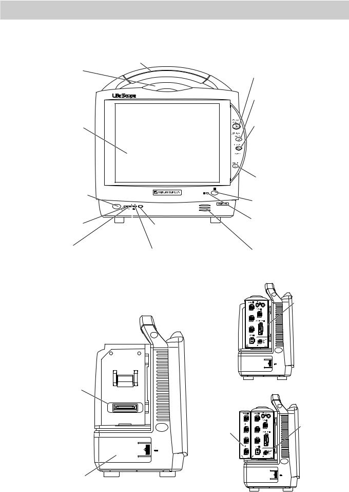
Panel Description
MU-631R Main Unit
Front Panel
Alarm indicator
Red or yellow lamp blinks, or yellow or cyan lamps lights according to the alarm settings. Green lamp blinks in synchronization with the patient’s QRS or pulse.
Touch screen
Displays monitoring data. Touching a key or data on the screen changes the displayed screen and settings.
Power switch
Press and hold for more than one second to turn the monitor power on.
When turning the monitor power off, press and hold for more than three seconds.
Power lamp
Lights when the monitor power is turned on.
AC power lamp
Lights when the power cord is connected between the
AC SOURCE socket and AC outlet.
Handle
For carrying the monitor.
|
|
Remote control sensor |
Battery lamp 1 |
Receives an infrared signal |
|
Indicates a battery |
from the remote control. |
|
status of the battery |
Battery lamp 2 |
|
in the battery slot 1. |
Indicates a battery status of |
|
|
|
the battery in the battery slot 2. |
Silence Alarms key
Silences the alarm sound.
NIBP Interval key
Selects NIBP measurement mode. Pressing this key changes the mode.
NIBP Start/Stop key
Starts NIBP measurement in selected mode. Pressing the key during measurement stops measurement.
 Menu key
Displays the MENU window.
Home key
Closes all opened windows and displays the home screen.
Record/Stop key (option)
Press to start or stop recording.
Error lamp (option)
Blinks when out of paper. Lights when the recorder door is open.
Speaker
For alarm and sync sound.
Left Side Panel
AY-673P
Input unit socket
Connects an AY series input unit.
Battery pack holder 1 (Battery slot 1)
For an SB-671P battery pack.
When the AY-673P input unit installed
AY-673P
AA-674P
When the AY-673P input unit and AA-674P smart expansion unit are installed
Operator’s Manual BSM-6000 |
13 |

Right Side Panel
SD card slot
For an SD card or program card. 
Recorder module holder
For the WS-671P recorder module. 
ZS socket


 For the ZS-900P* transmitter.
Network socket
Connects to monitor network system


 via the network separation unit.


Battery pack holder 2 (Battery slot 2)
For an SB-671P battery pack.
* ZS-900P transmitter is not available for BSM-6000A series. |
When the WS-671P recorder module is installed |
|
Rear Panel
Example shows the QI-631P and QI-632P interfaces installed.
QI-632P/QI-634P interface socket |
QI-631P interface socket |
Connects the QI-632P or QI-634P |
Connects the QI-631P interface. |
interface. |
|
USB socket (QI-632P/QI-
Connects a mouse or bar code reader.
Multi-link socket (QI-632P/QI-634P)
Connects a QF interface, IF series communication cable or multi-link cable of an external unit.
Alarm socket (QI-632P)
Connects a YJ-672P nurse call cable.
RS-232C socket (QI-631P)
Not available.
RGB socket (QI-631P)
Outputs the RGB video signal. Connects to the slave display.
AC SOURCE power cord socket |
Equipotential grounding terminal |
For the AC power cord. |
For an equipotential grounding lead. |
14 |
Operator’s Manual BSM-6000 |
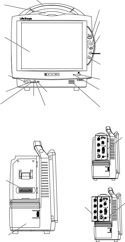
MU-651R/MU-671R Main Unit
Front Panel
Alarm indicator
Red or yellow lamp blinks, or yellow or cyan lamps lights according to the alarm settings. Green lamp blinks in synchronization with the patient’s QRS or pulse.
Touch screen
Displays monitoring data. Touching a key or data on the screen changes the displayed screen and settings.
Power switch
Press and hold for more than one second to turn the monitor power on.
When turning the monitor power off, press and hold for more than three seconds.
Power lamp
Lights when the monitor power is turned on.
AC power lamp
Lights when the power cord is connected between the
AC SOURCE socket and AC outlet.
Handle
For carrying the monitor.
|
|
Silence Alarms key |
|
|
|
Silences the alarm sound. |
|
|
|
NIBP Interval key |
|
|
|
Selects NIBP measurement mode. |
|
|
|
Pressing this key changes the mode. |
|
|
|
NIBP Start/Stop key |
|
|
|
Starts NIBP measurement in selected |
|
|
|
mode. Pressing the key during |
|
|
|
measurement stops measurement. |
|
|
|
Menu key |
|
|
|
Displays the MENU window. |
|
|
|
Home key |
|
|
|
Closes all opened windows and |
|
|
|
displays the home screen. |
|
|
|
Record/Stop key (option) |
|
|
|
Press to start or stop recording. |
|
|
Remote control sensor |
Error lamp (option) |
|
|
Blinks when out of paper. |
||
|
Receives an infrared signal |
||
Battery lamp 1 |
Lights when the recorder |
||
Indicates a battery |
from the remote control. |
door is open. |
|
status of the battery |
Battery lamp 2 |
Speaker |
|
in the battery slot 1. |
Indicates a battery status of |
||
For alarm and sync sound. |
|||
|
the battery in the battery slot 2. |
||
|
|
Left Side Panel
Input unit socket
Connects an AY series input unit.
Battery pack holder
For an SB-671P battery pack.
AY-673P
When the AY-673P input unit installed
AY-673P
AA-674P
When the AY-673P input unit and AA-674P smart expansion unit are installed
Operator’s Manual BSM-6000 |
15 |
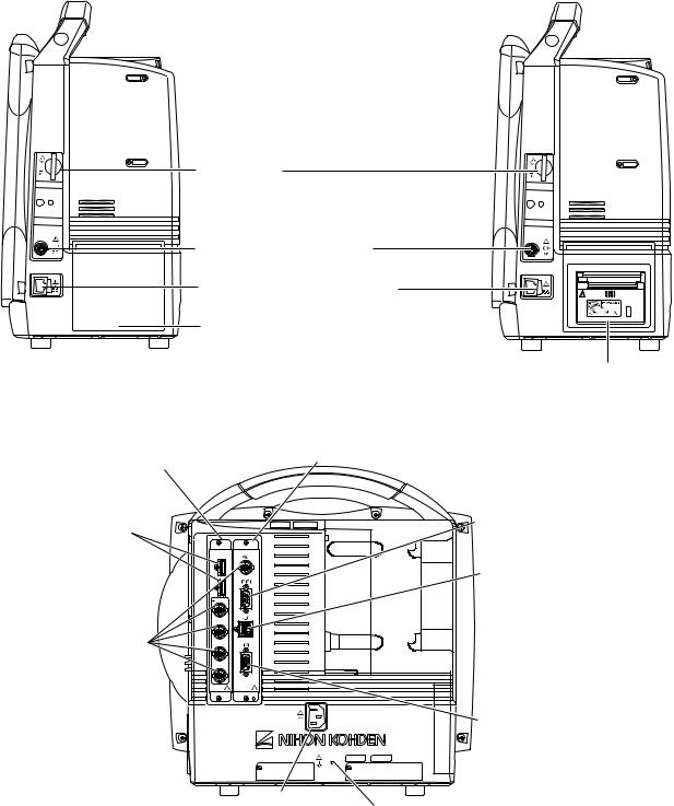
Right Side Panel
SD card slot
For an SD card or program card.
ZS socket
For the ZS-900P* transmitter.
Network socket
Connects to monitor network system
via the network separation unit.
Recorder module holder
For the WS-671P recorder module.
* ZS-900P transmitter is not available for BSM-6000A series. When the WS-671P recorder module is installed
Rear Panel
QI-672P interface socket
Connects the QI-672P interface.
USB sockets
Connects a mouse or bar code reader.
Multi-link sockets
Connects a QF series interface, IF series communication cable or multi-link cable of an external unit.
QI-671P interface socket
Connects the QI-671P interface.
RS-232C socket
Not available.
Alarm socket
Connects a YJ-672P nurse call cable.
RGB socket
Outputs the RGB video signal. Connects to the dual display or slave display.
AC SOURCE power cord socket |
Equipotential grounding terminal |
|
For the AC power cord. |
||
For an equipotential grounding lead. |
||
|
16 |
Operator’s Manual BSM-6000 |
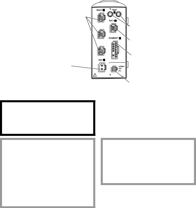
AY-631P/AY-633P/AY-651P/AY-653P/AY-660P/AY-661P/AY-663P/AY-671P/AY-673P Input Unit
Front Panel
AY-660P: One TEMP socket, one MULTI socket, no ECG/BP OUT socket AY-631P/AY-651P/AY-661P/AY-671P: Two TEMP sockets, one MULTI socket AY-633P/AY-653P/AY-663P/AY-673P: Two TEMP sockets, three MULTI sockets
Example is AY-673P input unit.
MULTI socket
Connects to the connection cord of the parameter to be monitored (IBP, temperature, CO, CO2, O2, respiration by thermistor method, SpO2-2 (AY-661P/663P/671P/ 673P only) or BIS). The type of
parameter is automatically recognized.
NIBP socket
Connects to the air hose.
TEMP socket
Connects to the temperature probe cord.
SpO2 socket
Connects to the SpO2 connection cord.
ECG/RESP socket
Connects to the ECG connection cord.
ECG/BP OUT socket
Outputs 100 mmHg/V IBP waveform and
1 mV/V ECG waveform and heart rate trigger by using the YJ-910P or YJ-920P ECG/BP output cable. These analog signals can be used as the synchronization signal for other equipment, such as IABP.
WARNING
When performing defibrillation during cardiac output monitoring, never touch the CO connection cord. The discharged energy may cause electrical shock or injury.
CAUTION
When using the output signal from the monitor as the synchronization signal for other equipment such as an IABP (intra-aortic balloon pump) or defibrillator:
•Set the timing of the IABP by checking the waveform on the IABP screen.
•Check the condition of the bedside monitor at all times. The output signal may become unstable.
•Check that the delay time of the output signal is within the range of the connected equipment.
CAUTION
Only a Nihon Kohden defibrillator can use the output signal from the monitor as a synchronization signal. Check that the delay time of the output signal (heart rate trigger 20 ms maximum) is within the range of the connected defibrillator.
Operator’s Manual BSM-6000 |
17 |
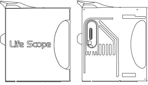
NOTE:
•When using an IBP waveform as a synchronization signal for other equipment, connect the IBP line to the MULTI socket on the input unit. The IBP waveform that is used for the synchronization signal depends on the “IBP ANALOG OUT” setting in the SYSTEM SETUP window.
-When “IBP ANALOG OUT” is set to “FIXED POSITION”:
The IBP line connected to the top MULTI socket on the input unit is used.
-When “IBP ANALOG OUT” is set to “HIGHEST PRIORITY LABEL” :
When more than one IBP waveform is acquired, the IBP waveform of the highest priority label is used.
IBP label priority:
ART > ART2 > RAD > DORS > AO > FEM > UA > LVP > P1 > P2 > P3 > P4 > P5 > P6 > P7
•Analog ECG, analog BP and heart rate trigger output are not available when an AY-660P input unit is used.
•The output signal from the ECG/BP OUT socket may become unstable in the following conditions.
-Electrode is dry or detached.
-Electrode lead is damaged or disconnected from the electrode.
-Electrode lead is pulled.
-AC interference or EMG noise superimposed.
-Air bubbles or blood clog in the circuit for monitoring IBP.
-Cord or cable is disconnected or damaged.
•All instruments which are to be connected to the ECG/BP OUTPUT socket must use a YJ910P or YJ-920P ECG/BP output cable and comply with the IEC 60601-1 safety standard for medical equipment.
Left Side Panel
When the side panel is removed
|
|
|
|
|
|
|
|
|
|
|
|
|
|
|
|
|
|
|
|
|
|
|
|
|
|
|
|
|
|
|
|
|
|
|
|
|
|
|
|
|
|
|
|
|
|
|
|
|
|
|
|
|
|
|
|
|
|
|
|
|
|
|
|
|
|
|
|
|
|
|
|
|
|
|
|
|
|
|
|
|
|
|
|
|
|
|
|
|
|
|
|
|
|
|
|
|
|
|
|
|
|
|
|
|
|
|
|
|
|
|
|
|
|
|
|
|
|
|
|
|
|
|
|
|
|
|
|
|
|
|
|
|
|
|
|
|
|
|
|
|
|
|
|
|
|
|
|
|
|
|
|
|
|
|
|
|
|
|
|
|
|
|
|
|
|
|
|
|
|
|
|
|
|
|
|
|
|
|
|
|
|
|
|
|
|
|
|
|
|
|
|
|
|
|
|
|
|
|
|
|
|
|
|
|
|
|
|
|
|
|
|
|
|
|
|
|
|
|
|
|
|
|
|
|
|
|
|
|
|
|
|
|
|
|
|
|
|
|
|
|
|
|
|
|
|
|
|
|
|
|
|
|
|
|
|
|
|
|
|
|
|
|
|
|
|
|
|
|
|
|
|
|
|
|
|
|
|
|
|
|
|
|
|
|
|
|
|
|
|
|
|
|
|
|
|
|
|
|
|
|
|
|
|
|
|
|
|
|
|
|
|
|
|
|
|
|
|
|
|
|
|
|
|
|
|
|
|
|
|
|
|
|
|
|
|
|
|
|
|
|
|
|
|
|
|
|
|
|
|
|
|
|
|
|
|
|
|
|
|
|
|
|
|
|
|
|
|
|
|
|
|
|
|
|
|
|
|
|
|
|
|
|
|
|
|
|
|
|
|
|
|
|
|
|
|
|
|
|
|
|
|
|
|
|
|
|
|
|
|
|
|
|
|
|
|
|
|
|
|
|
|
|
|
|
|
|
|
|
|
|
|
|
|
|
|
|
|
|
|
|
|
|
|
Side panel |
|
|
Smart expansion unit socket |
|||||||||||||||||||||||||||||||||
Remove to attach an AA-672P or AA-674P |
|
|
Connects an AA-672P or AA-674P smart expansion unit. |
|||||||||||||||||||||||||||||||||
smart expansion unit. |
|
|
|
|
|
|
|
|
|
|
|
|
|
|
|
|
|
|
|
|
||||||||||||||||
18 |
Operator’s Manual BSM-6000 |
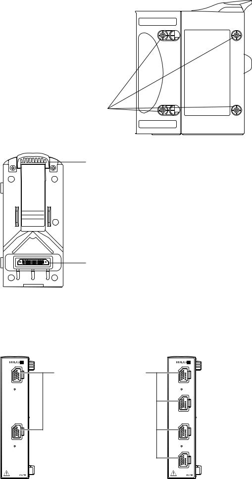
Right Side Panel
Tabs
Match the tabs on the input unit to the slots on the bedside monitor.
Rear Panel
Lock release lever
Lift up the lever to remove the input unit from the bedside monitor.
Input unit socket
For connecting a bedside monitor.
AA-672P/AA-674P Smart Expansion Unit
Front Panel |
|
AA-672P |
AA-674P |
|
MULTI socket |
|
Connects to the connection cord of |
|
the parameter to be monitored |
|
(IBP, temperature, CO, CO2, O2, |
|
respiration by thermistor method, |
|
SpO2-2 (AY-661P/663P/671P/ |
|
673P only) or BIS). The type of |
|
parameter is automatically recognized. |
Operator’s Manual BSM-6000 |
19 |
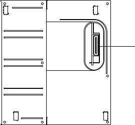
Right Side Panel
Connector
Connects an AY-631P, AY-633P, AY-651P, AY-653P,
AY-661P, AY-663P, AY-671P or AY-673P input unit.
20 |
Operator’s Manual BSM-6000 |
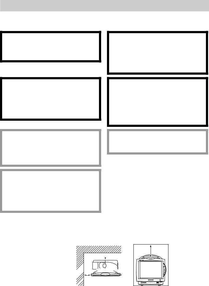
Installation
General
The monitor must be installed by qualified personnel. Details are in theAdministrator’s Guide.
WARNING
Only use the provided power cord. Using other power cords may result in electrical shock or injury to the patient and operator.
WARNING
When several medical instruments are used together, ground all instruments to the same onepoint ground. Any potential difference between instruments may cause electrical shock to the patient and operator.
WARNING
Connect only the specified instrument to the monitor and follow the specified procedure. Failure to follow this warning may result in electrical shock or injury to the patient and operator, and cause fire or instrument malfunction.
WARNING
•Do not install the monitor and optional units above the patient.
•Only use the specified tools or equipment when installing the monitor and units. Failure to follow this warning may result in the monitor or unit falling and injuring the patient.
CAUTION
Only use the specified stand, cart or equipment for installing the monitor and instruments. Using nonspecified equipment may result in the instruments falling and causing injury.
CAUTION
When not using the specified cart, carefully set the monitor to prevent it from falling off or tipping over.
CAUTION
Before connecting or disconnecting instruments, make sure that each instrument is turned off and the power cord is disconnected from the AC socket. Otherwise, the patient or operator may receive electrical shock or injury.
Make sure that there is more than 5 cm of space between the monitor and the wall for adequate ventilation. When the monitor is surrounded, make sure that there is about 10 cm of space above the monitor for ventilation so that the operating temperature does not exceed 40°C (104°F).
10 cm
 5 cm Rear Panel
 5 cm
5 cm 


 Side Panel
Operator’s Manual BSM-6000 |
21 |

Grounding the Monitor
When more than one electrical instrument is used, there may be electrical potential difference between the instruments. The potential difference between the instruments may cause current to flow to the patient connected to the instruments, resulting in electrical shock (micro shock).
When equipotential grounding is required, connect the equipotential ground terminal on the instrument to the equipotential ground terminal on the wall (equipotential grounding system) with the equipotential grounding lead (potential equalization conductor).
NOTE:
•For details on connecting an external instrument to the monitor, contact your Nihon Kohden representative.
•Leakage current may increase when interconnecting many medical instruments to the monitor.
Environment for External Instruments
Use external instruments in the following environment.
|
|
|
|
|
Medically-used room |
|
|
|
|
Non-medically used room |
|||||||||
|
|
|
Patient Environment |
Outside the Patient Environment |
|||||||||||||||
|
|
|
|
|
|
|
|||||||||||||
BSM-6301/6501/6701 |
|
|
|
|
|
|
|
|
|
|
|
|
|
|
|
||||
|
|
|
|
|
|
|
|
|
|
|
|
|
|
|
|
|
|
|
|
|
|
|
Interface |
|
|
|
|
|
|
|
|
|
|
|
|
|
|
|
|
|
|
|
QI-631P |
|
|
|
|
|
|
|
|
|
|
|
|
Sub display |
|
||
|
|
|
(For MU-631R) |
|
|
|
|
|
|
|
|
|
|
|
|
|
|||
|
|
|
|
|
|
|
|
|
|
|
|
|
|
|
(IEC 60601-1 complied or |
|
|||
|
|
|
|
|
|
|
|
|
|
|
|
|
|
|
|
|
|
||
|
|
|
|
|
|
|
|
|
|
|
|
|
|
|
|
|
using the isolation transformer |
|
|
|
|
|
Interface |
|
|
|
|
|
|
|
|
Sub display |
|
|
complied to IEC 60601-1) |
|
|||
|
|
|
|
|
|
|
|
|
|
|
|
|
|
|
|
||||
|
|
|
QI-671P |
|
|
|
|
|
|
|
|
(IEC 60601-1 complied or |
|
|
|
|
|
||
|
|
|
|
|
|
|
|
|
|
|
|
|
|
|
|||||
|
|
|
(For MU-651R/671R) |
|
|
|
|
|
|
|
|
using the isolation transformer |
|
|
|
|
|
||
|
|
|
|
|
|
|
|
Multigas unit |
|
complied to IEC 60601-1) |
|
|
|
|
|
||||
|
|
|
|
|
|
|
|
|
|
|
|
|
|||||||
|
|
|
|
|
|
|
|
|
|
|
|
|
|
|
|
||||
|
|
|
|
|
|
|
|
GF-110PA/210R* |
|
|
|
|
|
|
|
|
|||
|
|
|
|
|
|
|
|
|
|
|
|
|
|
|
|
||||
|
|
|
|
|
|
|
|
Multigas/Flow unit |
|
|
|
|
|
|
|
|
|||
|
|
|
|
|
|
|
|
GF-120PA*/220R* |
|
|
|
|
|
|
|
|
|||
|
|
|
|
|
|
|
|
|
|
|
|
|
|
|
|
|
|||
|
|
|
|
|
|
|
|
|
|
|
|
|
|
|
|
|
|||
|
|
|
|
|
|
|
|
Neuro unit |
|
|
|
|
|
|
|
|
|||
|
|
|
|
|
|
|
|
AE-918P* |
|
|
|
|
|
|
|
|
|||
|
|
|
|
|
|
|
|
|
|
|
|
|
|
|
|
|
|
|
|
|
|
|
Interface |
|
|
|
|
|
|
|
|
|
|
|
|
|
|
|
|
|
|
|
|
|
|
Interface |
|
|
|
|
|
|
|
|
|||||
|
|
|
QI-632P/634P |
|
|
|
|
|
|
|
|
|
|
|
|||||
|
|
|
(For MU-631R) |
|
|
|
QF series |
|
|
|
|
|
|
|
|
||||
|
|
|
|
|
|
|
|
|
|
|
|
|
|
||||||
|
|
|
QI-672P |
|
|
|
Communication |
|
|
|
|
|
|
|
|
||||
|
|
|
|
|
|
|
|
|
|
|
|||||||||
|
|
|
(For MU-651R/671R) |
|
|
|
cable |
|
|
|
|
|
|
|
|
||||
|
|
|
|
|
|
|
|
|
|||||||||||
|
|
|
|
|
|
|
|
IF series |
|
|
|
|
|
|
|
|
|||
|
|
|
|
|
|
|
|
|
|
|
|
|
External |
|
|
|
|
|
|
|
|
|
|
|
|
|
|
|
|
|
|
|
instruments |
|
|
|
|
|
|
|
|
|
|
|
|
|
|
|
|
|
|
|
|
|
|
|
|||
|
|
|
|
|
|
|
|
|
|
|
|
|
(IEC 60601-1 complied) |
|
|
|
|
|
|
|
|
|
|
|
|
|
|
External |
|
|
|
|
|
|
|
|
|||
|
|
|
|
|
|
|
|
instruments |
|
|
|
|
|
|
|
|
|||
|
|
|
|
|
|
|
|
(IEC 60601-1 complied) |
|
|
|
|
|
|
|
|
|||
|
Main unit |
|
|
|
|
|
|
|
|
|
|
|
|
|
|
|
|
|
|
|
|
|
|
|
|
|
|
|
|
|
|
|
|
|
|
||||
|
MU-631R/ |
|
|
|
|
|
|
|
|
|
|
|
|
|
|
|
|
|
|
|
671R/651R |
|
|
|
|
|
Mouse |
|
|
|
|
|
|
|
|
||||
|
|
|
|
|
|
|
|
|
|
|
|
|
|
|
|
||||
|
|
|
|
|
|
|
|
Bar code reader |
|
|
|
|
|
|
|
|
|||
|
|
|
|
|
|
|
|
|
|
|
|
|
|
|
|
|
|
|
|
|
|
|
Input unit |
|
|
|
|
|
|
|
|
|
|
|
|
|
|
|
|
|
|
|
AY-660P* |
|
|
|
|
|
|
|
|
Remote controller |
|
|
|
|
|
|
|
|
|
|
|
|
|
|
|
|
|
|
|
|
|
|
|
|
|
|
|
|
|
|
|
|
|
|
|
|
|
|
|
|
RY-910PA |
|
|
|
|
|
|
|
|
|
|
|
|
|
|
|
|
|
|
|
|
|
|
|
|
|
|
|
|
|
|
|
|
|
|
|
|
|
|
|
|
|
|
|
|
|
|
|
|
|
Input unit |
|
|
|
|
|
|
|
|
|
|
|
|
|
|
|
|
|
|
|
AY-631P/633P |
|
|
|
Smart |
|
|
|
|
|
|
|
|
|
|||
|
|
|
AY-651P/653P |
|
|
|
expansion unit |
|
|
|
|
|
|
|
|
|
|||
|
|
|
|
|
|
|
|
|
|
|
|
|
|
||||||
|
|
|
AY-661P*/663P* |
|
|
|
AA-672P/674P |
|
|
|
|
|
|
|
|
|
|||
|
|
|
AY-671P/673P |
|
|
|
|
|
|
|
|
|
|
|
|
|
|
|
|
|
|
|
|
|
|
|
|
|
|
|
|
|
|
|
|
|
|
||
|
|
|
|
|
|
|
|
|
|
|
|
|
|
|
|
|
|
|
|
|
|
|
|
|
|
|
|
|
|
|
|
|
|
|
|
|
|
|
|
|
|
|
Recorder |
|
|
|
|
|
|
|
|
|
|
|
|
|
|
|
|
|
|
|
module |
|
|
|
|
|
|
|
|
|
|
|
|
|
|
|
|
|
|
|
|
|
|
|
|
|
|
|
|
|
|
|
|
|
|
||
|
|
|
WS-671P |
|
|
|
|
|
|
|
|
|
|
|
|
|
|
|
|
|
|
|
|
|
|
|
|
|
|
|
|
|
|
|
|
|
|
|
|
|
|
|
|
|
|
|
|
|
|
|
|
|
|
|
|
|
|
|
|
|
|
|
Transmitter |
|
|
|
|
|
|
|
|
|
|
|
|
|
|
|
|
|
|
|
ZS-900P |
|
|
|
|
|
|
|
|
|
|
|
|
|
|
|
|
|
|
|
|
|
|
|
|
Hyper isolation |
|
|
|
|
|
|
Central monitor |
|
|
||
|
|
|
|
|
|
|
|
transformer |
|
|
|
|
|
|
|
|
|||
|
|
|
|
|
|
|
|
|
|
|
|
|
|
Network printer |
|
|
|||
|
|
|
|
|
|
|
|
QW-100Y |
|
|
|
|
|
|
|
|
|||
|
|
|
|
|
|
|
|
|
|
|
|
|
|
(IEC xxx complied) |
|
|
|||
|
|
|
Wireless LAN |
|
|
|
(HIT-100) |
|
|
|
|
|
|
|
|
|
|||
|
|
|
|
|
|
|
|
|
|
|
|
|
|
||||||
|
|
|
station |
|
|
|
|
|
|
|
|
|
|
|
|
|
|
|
|
|
|
|
|
|
|
|
|
|
|
|
|
|
|
|
|
|
|
||
|
|
|
QI-320PA |
|
|
|
|
|
|
|
|
|
|
|
|
|
|
|
|
|
|
|
|
|
|
|
|
|
|
|
|
|
|
|
|
|
|
|
|
|
|
|
|
|
|
|
|
|
|
|
|
|
|
|
|
|
|
|
|
|
|
|
|
|
|
|
|
|
|
|
|
|
|
|
|
|
|
|
|
* These units are not available for BSM-6000A series.
22 |
Operator’s Manual BSM-6000 |

Warnings and Cautions for Connecting the Monitor to a Network
WARNING
Install all network devices, including printer and hubs, outside the patient environment (IEC 60601- 1-1). If they are installed inside the patient environment, the patient or operator may receive electrical shock or injury. For installation, contact your Nihon Kohden representative.
WARNING
Check the software version number of the monitor before connecting it to the network. Different software versions have different communication methods. More than one communication method in a network may cause communication failure. For details, refer to the Network and System Installation Guide.
WARNING
Connect the monitor to network as specified. Otherwise the patient and operator may receive electrical shock or injury. To connect the network, contact your Nihon Kohden representative.
WARNING
In a network where this monitor is connected, connect only the specified instruments. Unspecified instruments may cause electrical shock or injury to the patient and operator or cause instrument malfunction, instrument stop, or data loss.
WARNING
Do not use a damaged network cable. The patient or operator may receive electrical shock when the damaged part is touched.
CAUTION
When the monitor is connected to a central monitor network, set the Bed Name (Bed ID) and Group Name on the monitor. Otherwise, the default settings are used for the bed name and group name and the bed may be incorrectly identified on the central monitor.
CAUTION
The network must be managed by the network administrator. Make sure that each monitor in the network has a different IP address. Otherwise, data communication cannot be performed properly. When adding a monitor to an already operating network, set the IP address on the monitor before connecting the monitor to the network.
Operator’s Manual BSM-6000 |
23 |
Loading...