


SERVICE MANUAL
cardiofax Q
ELECTROCARDIOGRAPH
ECG-9110K, ECG-9130K
ECG-9130P, ECG-9132K
0634-001325B

CONTENTS
Contents
Conventions Used in this Manual and Instrument ....................................................................i
Warnings, Cautions and Notes ....................................................................................... i
Explanations of the Symbols in this Manual and Instrument .......................................... i
Section 1 General .................................................................................. 1C.1
Introduction .......................................................................................................................... 1.1
Service Policy ......................................................................................................................1.2
Specifications ......................................................................................................................1.3
Panel Description ................................................................................................................. 1.6
ECG-9110K Electrocardiograph ..................................................................................1.6
Top Panel ......................................................................................................... 1.6
Operation Panel................................................................................................1.7
Right Side Panel ..............................................................................................1.8
Left Side Panel.................................................................................................1.8
ECG-9130K/P Electrocardiograph .............................................................................. 1.9
Top View ........................................................................................................... 1.9
Operation Panel.............................................................................................. 1.10
Right Side Panel ............................................................................................ 1.11
Left Side Panel............................................................................................... 1.11
ECG-9132K Electrocardiograph ................................................................................ 1.12
Top View ......................................................................................................... 1.12
Operation Panel.............................................................................................. 1.13
Right Side Panel ............................................................................................ 1.14
Left Side Panel............................................................................................... 1.14
Composition ....................................................................................................................... 1.15
ECG-9110K Electrocardiograph ................................................................................ 1.15
ECG-9130K Electrocardiograph ................................................................................ 1.16
ECG-9130P Electrocardiograph ................................................................................ 1.17
ECG-9132K Electrocardiograph ................................................................................ 1.18
Location .............................................................................................................................. 1.19
Block Diagram .................................................................................................................... 1.20
Connection Diagram ........................................................................................................... 1.21
Section 2 Maintenance ......................................................................... 2C.1
Replacement ........................................................................................................................ 2.1
Periodic Replacement Schedule ................................................................................. 2.1
Cleaning and Greasing .........................................................................................................2.2
Cleaning and Greasing Schedules.............................................................................. 2.2
Cleaning the Thermal Head ........................................................................................ 2.2
Cleaning the Paper Mark Sensor and Paper Empty Sensor ........................................ 2.3
Cleaning the Motor Rotation Sensor and Greasing the Motor Gear and
Gear Meshed with Motor Gear ..............................................................................2.4
Service Manual ECG-9110/9130 Rev B C.1

CONTENTS
Section 3 Troubleshooting and System Error Message .................. 3C.1
Troubleshooting Flowchart .................................................................................................... 3.1
Troubleshooting Table ...........................................................................................................3.4
Troubleshooting General Operation Problem............................................................... 3.4
Troubleshooting Recording Problem ........................................................................... 3.6
System Error Message ......................................................................................................... 3.7
Section 4 System Test and Setting ..................................................... 4C.1
System Test ......................................................................................................................... 4.1
Overall ........................................................................................................................ 4.1
Calling up the Test Level 1 .........................................................................................4.2
Calling up the Test Level 2 .........................................................................................4.3
Entering the System Test Number .............................................................................. 4.4
Executing the System Test ........................................................................................ 4.5
Quitting the System Test ............................................................................................ 4.6
Exiting the System Test Mode ................................................................................... 4.6
Demonstration ......................................................................................................................4.7
Recorder ...............................................................................................................................4.8
Thermal Head ..................................................................................................................... 4.11
Key .....................................................................................................................................4.12
Memory .............................................................................................................................. 4.13
Single Memory Test Mode ........................................................................................ 4.14
Continuous Memory Test Mode ................................................................................ 4.14
LCD/LED ............................................................................................................................4.15
Input Unit ........................................................................................................................... 4.17
Calibration .......................................................................................................................... 4.18
Communication .................................................................................................................. 4.19
CRO/EXT1 ......................................................................................................................... 4.21
System Setup Initialization ................................................................................................ 4.23
ECG Findings List Recording ............................................................................................. 4.24
Recording Resolution Setting ............................................................................................. 4.25
Cue Mark Adjustment ......................................................................................................... 4.26
Date and Time Setting ........................................................................................................ 4.28
Setting the Date and Time ........................................................................................ 4.28
Section 5 Board/Unit Description ..........................................................5C.1
Block Diagram..................................................................................................................... 5.1
Power Unit ........................................................................................................................... 5.2
ECG CONTROL Board ....................................................................................................... 5.2
FLASH ROM Board ............................................................................................................ 5.3
INVERTER Board ............................................................................................................... 5.3
Section 6 Disassembly and Assembly ..................................................6C.1
Before You Begin ................................................................................................................. 6.1
Warnings and Cautions ............................................................................................ 6.1
Required Tools ............................................................................................................ 6.1
C.2 Service Manual ECG-9110/9130 Rev B

CONTENTS
Board and Unit Location ............................................................................................. 6.2
Cable Connection ....................................................................................................... 6.3
Removing the Top Casing Assy............................................................................................6.4
Removing the ECG CONTROL Board ..................................................................................6.5
Removing the Power Unit and POWER Board ......................................................................6.6
Replacing the Thermistor ............................................................................................ 6.7
Removing the Thermal Head ................................................................................................ 6.8
Removing the Thermal Head Only .............................................................................. 6.8
Removing the Thermal Head with the Thermal Head Bracket,
Thermal Head Spring and Thermal Head Axle ......................................................... 6.9
Removing the Motor Assy ................................................................................................. 6.10
Removing the Speaker Assy............................................................................................. 6.11
Removing the PAPER SENSOR Board Assy.................................................................... 6.12
Removing the Recorder Base ........................................................................................... 6.13
Removing the Battery Terminal Assy ................................................................................ 6.14
Removing the Magazine Assy .......................................................................................... 6.15
Removing the LCD Assy, INVERTER Board and LCD CN Board ..................................... 6.16
Removing the LCD Assy......................................................................................... 6.16
Removing the INVERTER Board ............................................................................ 6.17
Removing the LCD CN Board ................................................................................. 6.17
Removing the Membrane Assy Film Cable and KEY Board ............................................. 6.18
Removing the Membrane Assy Film Cable and KEY Board ................................... 6.18
Replacing the Membrane Assy Film Cable ............................................................. 6.19
Removing the Bottom Casing ........................................................................................... 6.20
Replacing the Fuse on the POWER Board ....................................................................... 6.21
Replacing the Lithium Battery on the ECG CONTROL Board .......................................... 6.22
Section 7 Adjustment .............................................................................7C.1
Adjusting Thermal Head Position ........................................................................................ 7.1
Changing Magazine Paper Width ........................................................................................ 7.5
Adjusting Backlash between Motor Gear and Platen Axle Assy Gear ................................ 7.6
Section 8 Replaceable Parts List......................................................... 8C.1
General Parts List ................................................................................................................8.2
Top Casing Assy .................................................................................................................. 8.6
Top Casing Assy, YZ-015H3 for ECG-9110K ..............................................................8.6
Top Casing Assy, YZ-014H4 for ECG-9130K ..............................................................8.7
Top Casing Assy, YZ-022H2 for ECG-9130P ..............................................................8.8
Top Casing Assy, YZ-035H7 for ECG-9132K ..............................................................8.9
Motor Assy, YZ-014H1 ....................................................................................................... 8.10
Gear Assy, YZ-014H0 .........................................................................................................8.11
Battery Terminal Assy, YZ-014H5 .......................................................................................8.12
LCD Top Casing Assy, YZ-013H9 ....................................................................................... 8.13
Cart ....................................................................................................................................8.14
KC-010A Cart ........................................................................................................... 8.14
KD-010A Cart ........................................................................................................... 8.16
Patient Cable Hanger .......................................................................................................... 8.18
Service Manual ECG-9110/9130 Rev B C.3

CONTENTS
Section 9 Connector Pin Assignment ................................................ 9C.1
Power Unit ............................................................................................................................ 9.1
CN101 (to AC Inlet) ....................................................................................................9.1
CN21 (to ECG CONTROL Board) ...............................................................................9.1
CN301 (to Thermal Head) ........................................................................................... 9.1
CN501 (to Battery) .....................................................................................................9.1
ECG CONTROL Board ......................................................................................................... 9.2
CNJ011 (to Thermal Head) ......................................................................................... 9.2
CNJ021 (to FLASH ROM Board) ................................................................................9.2
CNJ032 (to Key Connector)........................................................................................ 9.4
CNJ033 (to KEY Board) .............................................................................................9.4
CNJ035 (to Power Unit) .............................................................................................. 9.5
CNJ091 (to ECG Connector) ...................................................................................... 9.5
CNJ101 (to SIO Connector) .......................................................................................9.6
CNJ102 (to PAPER SENSOR Board) ........................................................................9.6
CNJ103 (to Motor Assy) .............................................................................................9.6
CNJ111 (to PC Card) .................................................................................................. 9.7
CNJ121 (to LCD CN Board) ........................................................................................ 9.7
CNJ401 (to CRO Connector) ...................................................................................... 9.7
CNJ402 (to EXT INPUT1 Connector) ......................................................................... 9.7
CNJ403 (to EXT INPUT2 Connector) ......................................................................... 9.7
FLASH ROM Board ..............................................................................................................9.8
CNJ021 (to ECG CONTROL Board) ........................................................................... 9.8
INVERTER Board ............................................................................................................... 9.10
CN1 (to ECG CONTROL Board) ...............................................................................9.10
CN2 (to LCD Module) ............................................................................................... 9.10
External Input/Output Socket .............................................................................................9.11
SIO Socket .............................................................................................................. 9.11
EXT Input and CRO Output ...................................................................................... 9.11
C.4 Service Manual ECG-9110/9130 Rev B

Conventions Used in this Manual and Instrument
Warnings, Cautions and Notes
Warnings, cautions and notes are used in this manual to alert or signal the reader to specific information.
WARNING
A warning alerts the user to possible injury or death associated with the use or misuse of the instrument.
CAUTION
A caution alerts the user to possible injury or problems with the instrument associated with its use or
misuse such as instrument malfunction, instrument failure, damage to the instrument, or damage to other
property.
NOTE
A note provides specific information, in the form of recommendations, requirements, alternative methods
or supplemental information.
Explanations of the Symbols in this Manual and Instrument
The following symbols found in this manual/instrument bear the respective descriptions as given.
Cardiograph
Attention, consult
operator’s manual
Equipotential terminal
Serial input/output terminal
Input terminal for analog
signal
Output terminal for analog
signal
Eject (magazine release
button)
Type CF applied part
The CE mark is a protected
conformity mark of
European Community.
The products herewith
comply with the
requirements of the
Medical Device Directive
93/42/EEC.
Battery
Service Manual ECG-9110/9130 Rev A i
Memory card slot

Operation panel (for ECG-9110K only)
Alternating current
“On” only for a part of
equipment
“Off” only for a part of
equipment
Battery charging
Battery check lamp
QRS sync lamp
Rhythm recording
Age
Paper speed
Gain
Reset
Paper feed
Filter
Copy
Calibration
START/STOP recording
Automatic control
Manual control
Periodic recording
Mark
ii Service Manual ECG-9110/9130 Rev A

Operation panel (for ECG-9130K only)
Alternating current
“On” only for a part of
equipment
“Off” only for a part of
equipment
Battery charging
Battery check
Display (for ECG-9130K only)
Mode
Rhythm
Paper feed
Mark
Filter
Copy
Calibration
START/STOP recording
Automatic control
Manual control
Patient cable
QRS sync mark
Attention, consult
operator’s manual
Defibrillation-proof
Type CF applied part
Service Manual ECG-9110/9130 Rev A iii

Section 1 General
Introduction ........................................................................................................................ 1.1
Service Policy .................................................................................................................... 1.2
Specifications ..................................................................................................................... 1.3
Panel Description ............................................................................................................... 1.6
ECG-9110K Electrocardiograph .............................................................................. 1.6
Top Panel ....................................................................................................... 1.6
Operation Panel ............................................................................................. 1.7
Right Side Panel ............................................................................................ 1.8
Left Side Panel .............................................................................................. 1.8
ECG-9130K/P Electrocardiograph ........................................................................... 1.9
Top View ........................................................................................................ 1.9
Operation Panel ........................................................................................... 1.10
Right Side Panel .......................................................................................... 1.11
Left Side Panel ............................................................................................ 1.11
ECG-9132K Electrocardiograph ............................................................................ 1.12
Top View ...................................................................................................... 1.12
Operation Panel ........................................................................................... 1.13
Right Side Panel .......................................................................................... 1.14
Left Side Panel ............................................................................................ 1.14
Composition ..................................................................................................................... 1.15
ECG-9110K Electrocardiograph ............................................................................ 1.15
ECG-9130K Electrocardiograph ............................................................................ 1.16
ECG-9130P Electrocardiograph ............................................................................ 1.17
ECG-9132K Electrocardiograph ............................................................................ 1.18
Location ........................................................................................................................... 1.19
Block Diagram.................................................................................................................. 1.20
Connection Diagram ........................................................................................................ 1.21
Service Manual ECG-9110/9130 Rev B 1C.1

Introduction
1. GENERAL
This service manual provides useful information to qualified service personnel to
understand, troubleshoot, service, maintain and repair the ECG-9110K, ECG-
9130K/P and ECG-9132K Electrocardiograph (referred to in this service manual
as “the instrument”, “ECG-9110K” or “ECG-9130K” which includes ECG-9130P
and ECG-9132K).
All replaceable parts or units of this instrument and its optional units are clearly
listed with exploded illustration to help you locate the parts quickly.
The “System Test and Setting” and “Adjustment” sections in this service manual
describe the maintenance that should be performed by qualified service personnel.
The “Maintenance” section in the operator’s manual describes the maintenance
that can be performed by the user.
The information in the operator’s manual is primarily for the user. However, it is
important for service personnel to thoroughly read the operator’s manual and
service manual before starting to troubleshoot, service, maintain or repair this
instrument. This is because service personnel needs to understand the operation of
the instrument in order to effectively use the information in the service manual.
Service Manual ECG-9110/9130 Rev B 1.1

1. GENERAL
Service Policy
Nihon Kohden Corporation’s basic policy for technical service is to replace faulty
units, printed circuit boards or parts. We do not support component-level repair of
boards and units outside the factory for the following reasons:
• A special facility is necessary to repair multi-layer boards because most of the
components on the board are SMD (surface mount devices) and most of the
circuits employ a gate array method.
• To fulfill safety certification requirements, a special facility is necessary to verify
safety as medical equipment after the power unit is repaired.
NOTE
• When ordering parts or accessories from your nearest Nihon Kohden
Corporation’s distributor, please quote the NK code number and part
name which is listed in this service manual, and the name or model
of the unit in which the required part is located. This will help us to
promptly attend to your needs.
• Always use parts and accessories recommended or supplied by
Nihon Kohden Corporation to assure maximum performance from
your instrument.
1.2 Service Manual ECG-9110/9130 Rev B

Specifications
ECG input
Input impedance 10 MΩ or more
Electrode offset tolerance ±500 mV or more
Input unit protection Isolated and defibrillator protected only when the following
Standard sensitivity 10 mm/mV ±2%
Common mode rejection ratio 100 dB or more
Frequency response 0.05 to 150 Hz –3 dB or more
Waveform data processor
Sample rate 500 samples/s (input unit: 8,000 samples/s)
AC line filter 50/60 Hz
High-cut filter 75, 100, 150 Hz
EMG filter 25/35 Hz
Time constant 3.2 s or more
Waveform status detection Electrode detachment (polarization voltage),
1. GENERAL
specified patient cable is connected
Patient cable: BJ-901D, BJ-902D, BJ-903D, BA-901D, BA-903D
Noise (high frequency)
LCD (monochrome with CCFT backlight) (for ECG-9130K/P, ECG-9132K only)
Size 5.6 inch
Number of dots 320 × 240
ECG waveform 2.8 seconds simultaneous 12 lead ECG waveforms
Displayed data Waveform, patient information, recording settings,
operation mode, heart rate, QRS sync mark, error message,
electrode detachment, noise, patient information, hospital name
Recorder
Printing method High resolution thermal printer head
Printing density 200 dpi (8 dots/mm)
Scanning line density 1 ms
2 ms at paper speed 50 mm/s
Recording width 210 mm
Number of recording channels 3, 4, 6, 12
Sensitivity selection 1.25*, 2.5*, 5, 10, 20 mm/mV
*Automatically selected in automatic recording only
Paper speed 5, 10, 12.5, 25, 50 mm/s
Printed data Program type, version, date and time, paper speed, sensitivity,
lead name, filter, hospital name**, patient information**,
timing mark, event mark, electrode detachment, noise,
RESET mark*
*Printed only when ECG-9110K is used
**Printed only when ECG-9130K is used
Mechanical noise 48 dB or less at paper speed 25 mm/s
Service Manual ECG-9110/9130 Rev B 1.3

1. GENERAL
External input/output
External input 10 mm/0.5 V ±5%, input impedance 100 kΩ or more, 2 channel
Signal output 0.5 V/1 mV ±10%, output impedance 100 Ω or less
Serial I/O Communication method: RS-232C
Baud rate: 2400, 4800, 9600, 19200, 38400,
57600, 115200
Power requirement
Line voltage 100 to 127V, 220 to 240V AC ±10%
Line frequency 50 or 60 Hz
Power input Up to 150 VA
Power consumption 60 W or less
Built-in battery Voltage: 12 V
(LCT-1912ANK) Current consumption: 8 A or less
Battery operation time: Approx. 30 minutes
Environment
Operating temperature 10 to 40°C (50 to 104 F)
Operating humidity 25 to 90% RH
Operating atmospheric pressure 70 to 106 kPa
Storage duration and temperature 2 weeks or less: −20 to 60°C (−4 to 140 F)
(Depends on the battery) Between 2 weeks and one year: −15 to 40°C (5 to 104 F)
Over one year: −15 to 25°C (5 to 77 F)
Storage humidity 15 to 95% RH (non condensing)
Storage atmospheric pressure 70 to 106 kPa
Recording paper storage temperature −20 to 50°C (−4 to 122 F)
Recording paper storage humidity 25 to 80% RH
Electromagnetic compatibility IEC60601-1-2
CISPR11 Second Edition 1990-1999 Group 1 Class B
Other Indoor portable
Dimensions and weight
Dimensions 240 W × 104 H × 324 D mm (excluding protrusions)
Weight ECG-9110K: Approx. 3.8 kg (without battery)
ECG-9130K: Approx. 4.2 kg (without battery)
ECG-9130P: Approx. 4.2 kg (without battery)
ECG-9132K: Approx. 4.2 kg (without battery)
1.4 Service Manual ECG-9110/9130 Rev B

1. GENERAL
Safety
Safety standard:
IEC 60601-1 (1988), IEC 60601-1 Amendment 1 (1991), IEC 60601-1 Amendment 2 (1995)
IEC 60601-2-25 (1993), IEC 60601-2-25 Amendment 1 (1999)
Type of protection against electric shock:
AC power: Class I
Battery power: Internally powered equipment
Degree of protection against electric shock:
Defibrillator proof type CF applied part when patient cable BJ-901D, BJ-902D or BJ-903D is
used
Degree of protection against harmful ingress of water:
Ordinary equipment
Degree of safety of application in the presence of a flammable anaesthetic mixture with air, oxygen
or nitrous oxide:
Not suitable for use in the presence of a flammable anaesthetic mixture with air, oxygen or
nitrous oxide
Mode of operation:
Continuous
Performance
Performance standard: IEC 60601-2-51 (2003)
Service Manual ECG-9110/9130 Rev B 1.5

1. GENERAL
Panel Description
ECG-9110K
Electrocardiograph
Magazine
Top Panel
QRS sync lamp
Electrode
detachment
indicator
Operation panel
1.6 Service Manual ECG-9110/9130 Rev B
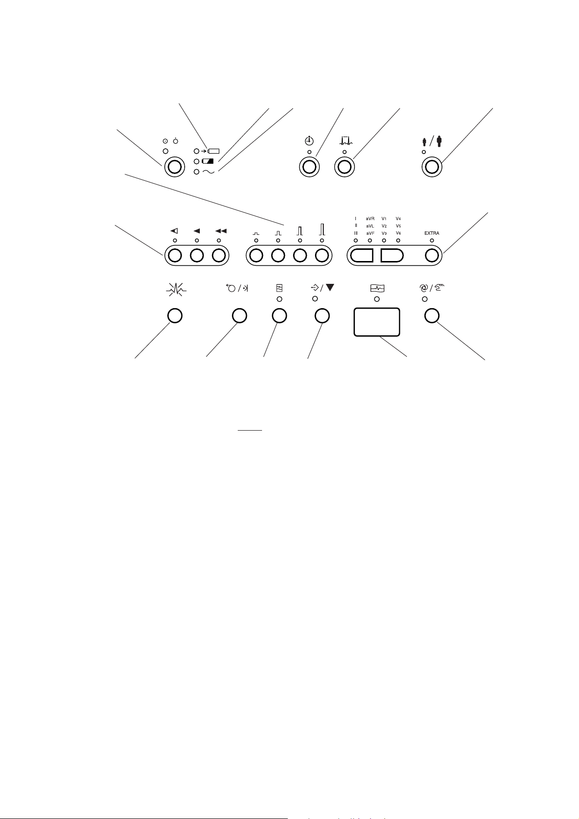
Operation Panel
1. GENERAL
1
9
8
11 12 1413
546
10
I
15 16
732
Name
1. POWER key
2. Battery charge lamp
3. Battery operation lamp
4. AC power lamp
5. PERIODIC key/lamp
6. RHYTHM key/lamp
7. AGE key/lamp
8. SPEED key/lamp
9. GAIN key/lamp
10. LEAD keys/lamp
11. RESET key
12. FEED/MARK key
13. FILTER key/lamp
14. COPY/CAL key/lamp
15. START/STOP key/lamp
16. AUTO/MANUAL key/lamp
Service Manual ECG-9110/9130 Rev B 1.7

1. GENERAL
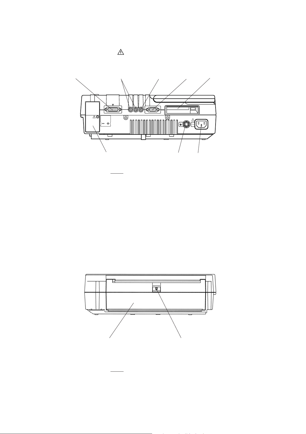
Right Side Panel
For the mark, refer to the descriptions for the Right Side Panel in Section 1
“Panel Descriptions” of the ECG-9110K Operator’s Manual.
21
19
Battery Pack
LCT-1912ANK
(
)
12v 1.9Ah
Name
17. Patient input connector
18. EXT-IN 1, 2 connector
19. CRO-OUT connector
20. SIO connector
21. Battery compartment
22. Equipotential ground terminal
23. AC power cord socket
22
2017 18
23
Left Side Panel
24 25
Name
24. Magazine
25. Magazine release button
1.8 Service Manual ECG-9110/9130 Rev B

1. GENERAL
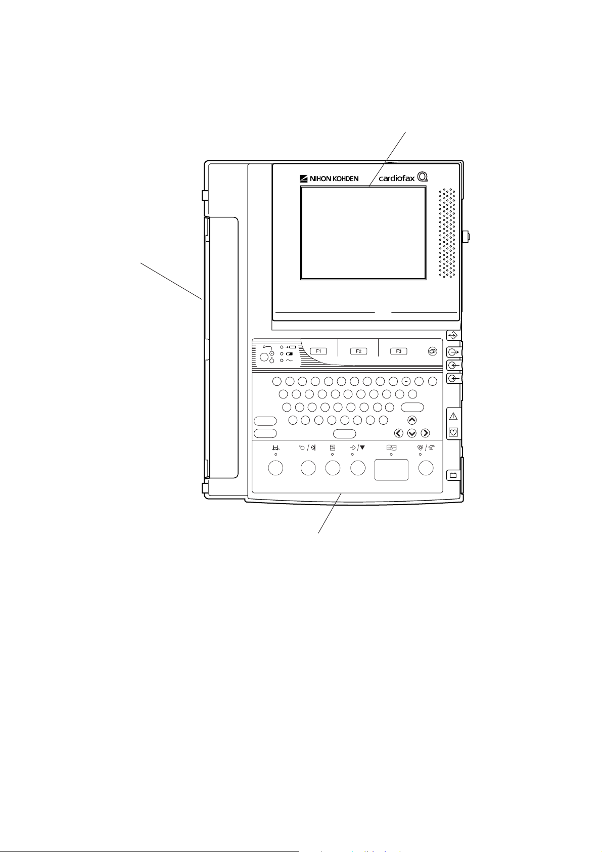
ECG-9130K/P
Electrocardiograph
Magazine
Top View
LCD screen
+
ENTER
ECG-9130K
ID
BS
SHIFT
ALT
2
1
3
Q
W
E
S
A
XYZ
67
4
5
R
T
G
F
D
C
V
B
SPACE
HIJ
N
9
0
8
O
U
P
K
L
.
M
Operation panel
The keyswithes on the ECG-9130P have a name label instead of the symbol.
Service Manual ECG-9110/9130 Rev B 1.9
1. GENERAL
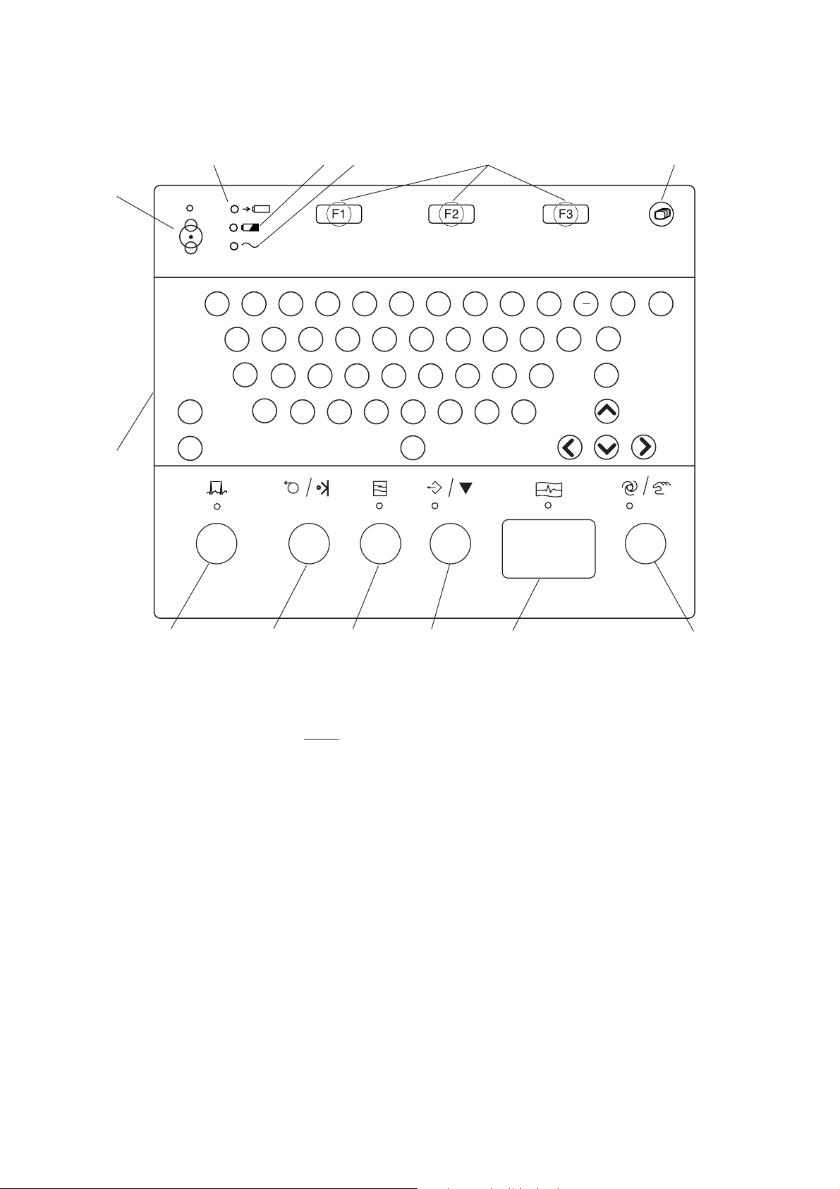
Operation Panel
32
4
65
1
2
1
Q
W
S
A
SHIFT
7
ALT
Z
4
3
R
E
F
D
C
X
5
T
G
V
67
U
Y
H
N
B
SPACE
J
9
8
I
K
M
0
P
+
ENTER
O
L
.
BS
ID
119108
Name
1. POWER key/lamp
2. Battery charge lamp
3. Battery operation lamp
4. AC power lamp
5. F1, F2, F3 function keys
6. MODE key
7. Keyboard
8. RHYTHM key/lamp
9. FEED/MARK key
10. FILTER key/lamp
11. COPY/CAL key/lamp
12. START/STOP key/lamp
13. AUTO/MANUAL key/lamp
12
ECG-9130K
13
1.10 Service Manual ECG-9110/9130 Rev B

1. GENERAL
Right Side Panel
For the mark, refer to the descriptions for the Right Side Panel in Section 1
“Panel Descriptions” of the ECG-9130K or 9130P Operator’s Manual.
14
Battery Pack
LCT-1912ANK
(
12v 1.9Ah
15
)
16 1817
19
Name
14. Patient input connector
15. EXT-IN 1, 2 connector
16. CRO-OUT connector
17. SIO connector
18. Memory card slot
19. Battery compartment
20. Equipotential ground terminal
21. AC power cord socket
20
21
Left Side Panel
22
Name
22. Magazine
23. Magazine release button
23
Service Manual ECG-9110/9130 Rev B 1.11
1. GENERAL
ECG-9132K
Electrocardiograph
Magazine
Top View
LCD screen
+
ENTER
BS
ECG-9132K
ID
1
Q
A
SHIFT
ALT
2 3 4 5 6 7
R
W
S
XYZ
T
DEF G HIJ K
C
V
B
SPACE
8 9 0
U
MN
O
P
L
.
Operation panel
The keyswithes on the ECG-9130P have a name label instead of the symbol.
1.12 Service Manual ECG-9110/9130 Rev B

Operation Panel
1. GENERAL
32
4
65
1
1
2 3 4 5 6 7
E
W
A
S
X
SHIFT
7
ALT
Z
R
D
C
Y
T
F G H
V
B
SPACE
8 9 0
U
J K
M
N
O
I
.
PQ
+
L
ENTER
BS
ID
119108
Name
1. POWER key/lamp
2. Battery charge lamp
3. Battery operation lamp
4. AC power lamp
5. F1, F2, F3 function keys
6. MODE key
7. Keyboard
8. RHYTHM key/lamp
9. FEED/MARK key
10. FILTER key/lamp
11. COPY/CAL key/lamp
12. START/STOP key/lamp
13. AUTO/MANUAL key/lamp
12
ECG-9132K
13
Service Manual ECG-9110/9130 Rev B 1.13
1. GENERAL
Right Side Panel
For the mark, refer to the descriptions for the Right Side Panel in Section 1
“Panel Descriptions” of the ECG-9132K Operator’s Manual.
14
Battery Pack
LCT-1912ANK
(
12v 1.9Ah
15
)
16 1817
19
Name
14. Patient input connector
15. EXT-IN 1, 2 connector
16. CRO-OUT connector
17. SIO connector
18. Memory card slot
19. Battery compartment
20. Equipotential ground terminal
21. AC power cord socket
20
21
Left Side Panel
22
Name
22. Magazine
23. Magazine release button
23
1.14 Service Manual ECG-9110/9130 Rev B

Composition
ECG-9110K
Electrocardiograph
1. GENERAL
ECG-9110K
RK-0011 Bottom Casing Assy
RK-0012 Internal Parts
GC-0012 Motor Assy
RH-0002 Magazine Assy
RK-0013 Thermal Head Assy
RK-0014 Battery Terminal Assy
RK-0015 PAPER SENSOR Board Assy
RK-0010 ECG-9100K Top Casing Assy
UT-2369 Key Board
SC-904D Power Unit
UT-235851 ECG Control Board
UT-23572 Flash ROM Board
(Option)
KC-010A Cart
KD-010A Cart
KD-104E Cart
KH-801E Patient Cable Hanger
DI-002A Pater Tray for KD-010A
DI-003A Mechano Cardiograph AMP tray
for KC-010A/JD-010A
• To order a replacement assembly above, use the Code No.
• To order a replacement component inside an assembly, refer to “Section 8
Replaceable Parts List”.
Service Manual ECG-9110/9130 Rev B 1.15

1. GENERAL
ECG-9130K
Electrocardiograph
ECG-9130K
RK-0011 Bottom Casing Assy
RK-0012 Internal Parts
GC-0012 Motor Assy
RH-0002 Magazine Assy
RK-0013 Thermal Head Assy
RK-0014 Battery Terminal Assy
RK-0015 PAPER SENSOR Board Assy
RK-0017 ECG-9130K Top Casing Assy
UT-2367 Key Board
VL-0002 LCD Assy
(Option)
UT-2368 LCD CN Board
SC-904D Power Unit
UT-2358 ECG Control Board
UT-23572 Flash ROM Board
KC-010A Cart
KD-010A Cart
KD-104E Cart
KH-801E Patient Cable Hanger
DI-002A Pater Tray for KD-010A
DI-003A Mechano Cardiograph AMP tray
for KC-010A/JD-010A
• To order a replacement assembly above, use the Code No.
• To order a replacement component inside an assembly, refer to “Section 8
Replaceable Parts List”.
1.16 Service Manual ECG-9110/9130 Rev B

ECG-9130P
Electrocardiograph
1. GENERAL
ECG-9130P
RK-0011 Bottom Casing Assy
RK-0012 Internal Parts
GC-0012 Motor Assy
RH-0002 Magazine Assy
RK-0013 Thermal Head Assy
RK-0014 Battery Terminal Assy
RK-0015 PAPER SENSOR Board Assy
RK-0038 ECG-9130P Top Casing Assy
UT-2367 Key Board
VL-0002 LCD Assy
(Option)
UT-2368 LCD CN Board
SC-904D Power Unit
UT-23584 ECG Control Board
UT-23575 Flash ROM Board
KC-010A Cart
KD-010A Cart
KD-104E Cart
KH-801E Patient Cable Hanger
DI-002A Pater Tray for KD-010A
DI-003A Mechano Cardiograph AMP tray
for KC-010A/JD-010A
• To order a replacement assembly above, use the Code No.
• To order a replacement component inside an assembly, refer to “Section 8
Replaceable Parts List”.
Service Manual ECG-9110/9130 Rev B 1.17
1. GENERAL
ECG-9132K
Electrocardiograph
ECG-9132K
RK-0011 Bottom Casing Assy
RK-0012 Internal Parts
GC-0012 Motor Assy
RH-0002 Magazine Assy
RK-0013 Thermal Head Assy
RK-0014 Battery Terminal Assy
RK-0015 PAPER SENSOR Board Assy
RK-0060 ECG-9132K Top Casing Assy
UT-2367 Key Board
VL-0002 LCD Assy
(Option)
UT-2368 LCD CN Board
SC-904D Power Unit
UT-23585 ECG Control Board
UT-2357E Flash ROM Board
KC-010A Cart
KD-010A Cart
KD-104E Cart
KH-801E Patient Cable Hanger
DI-002A Pater Tray for KD-010A
DI-003A Mechano Cardiograph AMP tray
for KC-010A/JD-010A
• To order a replacement assembly above, use the Code No.
• To order a replacement component inside an assembly, refer to “Section 8
Replaceable Parts List”.
1.18 Service Manual ECG-9110/9130 Rev B

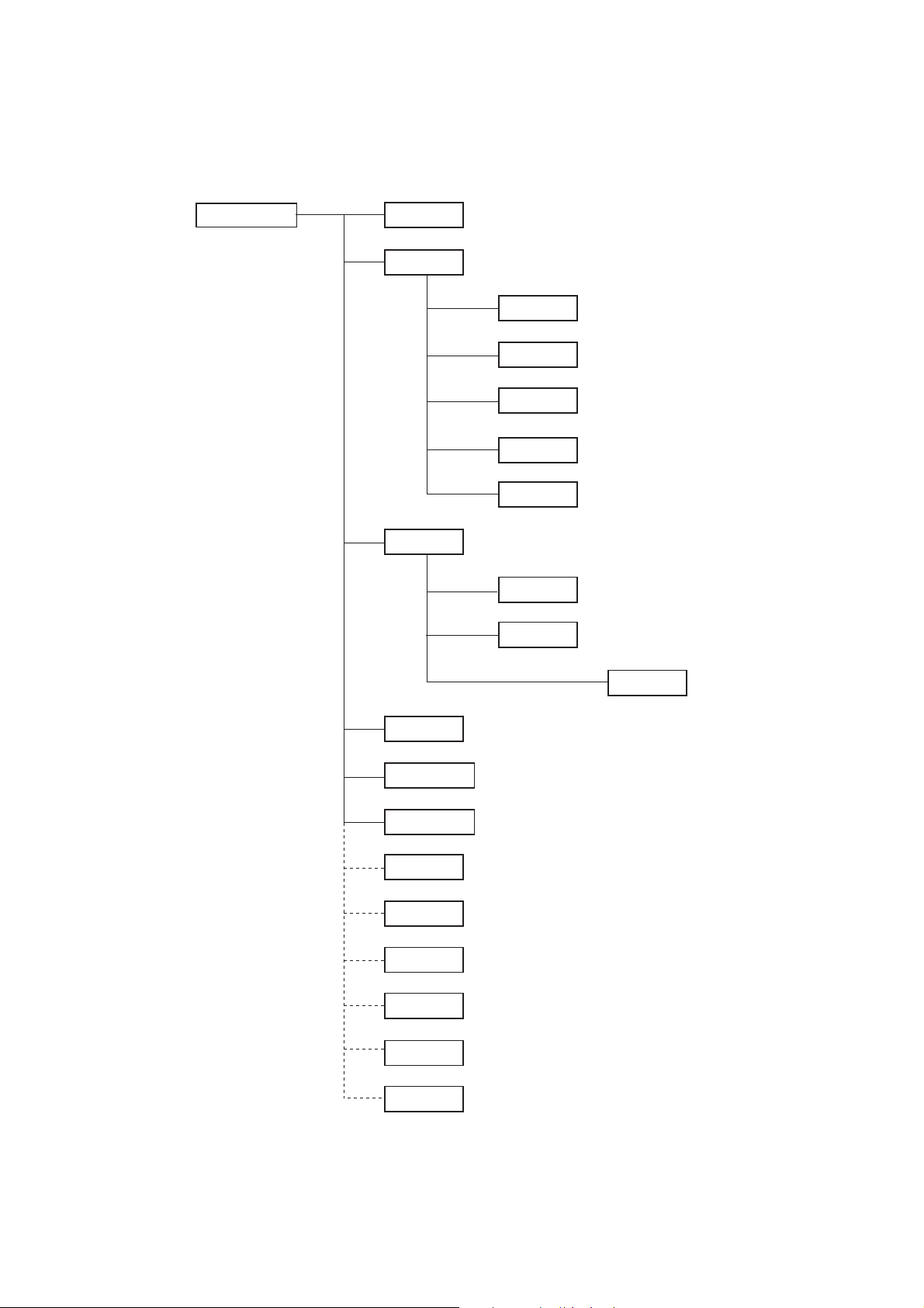
Location
1. GENERAL
Motor Assy
PAPER
SENSOR
Board Assy
Battery Terminal Assy
Thermal Head Assy
Speaker Assy
KEY Board
LCD Assy*
INVERTER Board*
LCD CN Board*
Power Unit
ECG CONTROL
Board
* for ECG-9130K/9130P/9132K only
Service Manual ECG-9110/9130 Rev B 1.19

1. GENERAL
Block Diagram
NOTE
The sheet key, LCD module, LCD CN board, INVERTER board and KEY
board are used for the ECG-9130K, ECG-9130P and ECG-9132K only.
Sheet Key
CNJ014
CNJ013
KEY Board
CNJ012
CNJ011
INVERTER Board
CRO OUTPUT
EXT INPUT2
EXT INPUT1
RS232C
PC CARD
ECG INPUT
CNJ041
CNJ112
for writing FPGA
CNJ042
ECG CONTROL
CNJ043
CNJ101
CNJ111
Floating area
CNJ091
CNJ021
CNJ011
FLASH ROM
Board
CNJ033
Board
CNA106
CNJ035
CNJ004
POWER
Board
CNJ121
CNJ032
CNJ102
CNJ103
CNJ011
CNA403
CNJ001
CNJ002
CNA104
CNA105
CNA102
CNA103
CNA101
Paper Sensor
Thermal Head
Temperature sensor
CNA402
CNA201
CNJ012
CNJ011 CNJ013
LCD CN
Board
Speaker
Motor Assy
Battery
LCD
CNJ003
CNA401
1.20 Service Manual ECG-9110/9130 Rev B

Connection Diagram
Index NK Code No. Description Remarks
101 51021-0500 L=60
102 547597A DF11-18DS-2C/51021-05 14 L=140
103 547588A DF11-16DS-2C/51021-1500 L=250 Not contain ferrite.*
104 547579A PHR-11/51021-1400 L=100 Not contain ferrite.*
105 547632 DF11-20DS-2C L=50
201 Directly attached to LCD
202 Directly attached to LCD.
203 547561A DF11-6DS-2C L=55
204
205 Directly attached to power unit
206 547623 DF-11-6DS-2C L=140
207 547614A EHR-6 L=95
208 547605 50-8B-04D/DF11-4DS-2C L=60
209 Directly attached to power unit
Not contain ferrite.*
1. GENERAL
1
2
3
301 Ground lead
302 Ground lead
303 Ground lead
304 Ground lead
* The following is the description with reagard to the ferrites used in the instrument.
NK Code No. Description
*1 550851 TFC-16-8-16
*2 442077 SFC-4
*3 550102 FPC-25-12
103
303
304
104
206
301
201
101
202
102
203
302
204
207
208
209
205
105
Service Manual ECG-9110/9130 Rev B 1.21

Section 2 Maintenance
Replacement...................................................................................................................... 2.1
Periodic Replacement Schedule.............................................................................. 2.1
Cleaning and Greasing ...................................................................................................... 2.2
Cleaning and Greasing Schedules .......................................................................... 2.2
Cleaning the Thermal Head..................................................................................... 2.2
Cleaning the Paper Mark Sensor and Paper Empty Sensor .................................... 2.3
Cleaning the Motor Rotation Sensor and Greasing the Motor Gear and
Gear Meshed with Motor Gear ........................................................................... 2.4
Service Manual ECG-9110/9130 Rev A 2C.1

Replacement
2. MAINTENANCE
This section describes the periodic replacement and cleaning of parts which are
required to maintain the instrument in good working condition.
This subsection only describes replacement schedule for parts that need to be
periodically replaced. The actual replacement procedures are described in the
section for Disassembly and Assembly. Read the whole “Disassembly and
Assembly” section, especially its Warnings and Cautions, before replacing any of
the parts described here.
Periodic Replacement
Schedule
To maintain the performance of the instrument, the parts listed in the table below
must be periodically replaced by qualified service personnel.
Part NK Code No. Description Recommendation
LCT-1912ANK 332543B Battery * See below.
KTJ-216-8MPF1-NK 357035 Thermal head After 30 km of
recording
LM32019T 545946 LCD Module After 10000 hours
Motor ASSY GC-0012 Motor ASSY After 1000 hours
BR2032/1F2 390765 Lithium battery** See below.
* Replace the battery when it cannot last for 15 minutes during battery operation
at the temperatures between 20 and30°C.
** Replace the lithium battery on the ECG CONTROL board when the No. 08 or
09 system error message appears or after the lithium battery is used for 7 years.
The life time of the battery is 7 years.
Service Manual ECG-9110/9130 Rev A 2.1

2. MAINTENANCE
Cleaning and Greasing
This subsection describes the cleaning and greasing procedures for parts that must
be cleaned and greased by qualified service personnel. The cleaning procedures
for parts that can be cleaned by the user are described in the Operator’s Manual.
Cleaning and Greasing
Schedules
Cleaning the Thermal Head
To maintain the performance of the instrument, the parts listed in the table below
must be regularly cleaned or greased.
Part Frequency Performed by
Instrument (external) After each use User
Thermal Head Once a month User
Platen Roller assy Once a year User
Paper Mark Detection Sensor Once a month Qualified service personnel
Paper Empty Sensor Once a month Qualified service personnel
Motor Sensor Once a year Qualified service personnel
Motor Gear and Gear Once a year Qualified service personnel
Meshed with Motor Gear
CAUTION
Before cleaning, turn the power off and disconnect the AC power cord
from the instrument.
Do not clean the thermal head just after recording because the head is
still hot.
Before setting the recording paper, clean the thermal head with the thermal head
cleaner. If the thermal head is dirty, printing quality is reduced.
When used for a log time, the thermal head may become dirty. If the thermal head
surface is touched with a dirty hand or if the recording paper is contaminated with
chlorides (CardioCream or physiological salt solution), these will be missing dots
on the recording. In this case, the thermal head requires cleaning.
Wipe the head section (copper color) behind the paper cutter with the thermal head
cleaner.
If the wheel gears are dirty, clean the gears with cotton moistened with alcohol.
2.2 Service Manual ECG-9110/9130 Rev A

2. MAINTENANCE
Cleaning the Paper Mark
Sensor and Paper Empty
Sensor
1. Remove the magazine. The illustration below shows the location of the paper
mark sensor and paper empty sensor.
2. Use a piece of cotton moistened with alcohol to clean both sensors.
Paper mark sensor
Paper empty sensor
Service Manual ECG-9110/9130 Rev A 2.3

2. MAINTENANCE
Cleaning the Motor
Rotation Sensor and
Greasing the Motor Gear
and Gear Meshed with
Motor Gear
1. Detach the top casing from the bottom casing as described in the “Disassembly
and Assembly” section.
2. Remove the three screws holding the motor assy to the bottom casing and
remove the motor assy.
3. Remove the two screws to expose the motor rotation sensor and photodiode.
Motor rotation sensor and
photodiode
Motor gear
Gear meshed
with motor gear
Motor assy
Bottom casing
4. Use a piece of cotton moistened with alcohol to clean the sensor and
photodiode.
5. Use a brush to clean the holes in the worm assy.
6. Use EM-50L (NK code No. 547712) grease to grease the motor gear and
the gear which directly meshes with the motor gear as shown below.
7. Reattach the MOTOR SENS board to the motor with the two screws.
8. Reattach the motor assy to the bottom casing with the two screws.
9. Reattach the top casing to the bottom casing as described in the
“Disassembly and Assembly” section.
2.4 Service Manual ECG-9110/9130 Rev A

Section 3 T roubleshooting and
System Error Message
Troubleshooting Flowchart ................................................................................................. 3.1
T roub leshooting T a ble......................................................................................................... 3.4
Troubleshooting General Operation Problem........................................................... 3.4
Troubleshooting Recording Problem........................................................................ 3.6
System Error Message ...................................................................................................... 3.7
Service Manual ECG-9110/9130 Rev A 3C.1

This section describes how to troubleshoot the instrument, using the following:
Is there any response when
any switch is pressed?
Check the cable connection
to the CNJ121 connector
on the ECG CONTROL
board all cable connections
on the LCD CN board.
The ECG CONTROL
board is faulty.
The ECG CONTROL board is
faulty.
The INVERTER board is faulty.
The power LED is on but
there is no LCD display.
Is the LCD backlight on?
Is the cable firmly
connected to the CNJ121
connector on the ECG
CONTROL board?
Yes
No
No
Yes
The LCD unit is faulty.
Normal
Yes
- flowchart
- troubleshooting table
- system error messages at power-up
Troubleshooting Flowc hart
Use the troubleshooting flowchart to find the possible sources of a problem.
Troubleshooting Flowchart
<ECG-9130K only>
3. TROUBLESHOOTING AND SYSTEM ERROR MESSAGE
Service Manual ECG-9110/9130 Rev A 3.1

3. TROUBLESHOOTING AND SYSTEM ERROR MESSAGE
The power of the
instrument does not turn
on.
Does the instrument
operate during AC
power operation?
Yes
Does the LED of the AC power
light?
The membrane key is faulty.
The ECG CONTROL board is faulty.
The POWER board is faulty.
The instrument does not
operate during battery
power operation.
Is the battery charged?
Yes
Yes
No
No
No
Charge the battery.
Check the cable connections to
the CNJ033 and CNJ035
connectors on the ECG CONTROL
board and the connector on the
INVERTER board.
Normal
Check the F0102 battery
fuse on the POWER board.
Normal
The POWER board is faulty.
Check the cable connection
to the CN501 connector on
the POWER board.
Normal
Is the F503 battery fuse on
the POWER board blown?
No
The power unit is faulty.
Yes
Replace the F503 battery
fuse on the POWER board.
3.2 Service Manual ECG-9110/9130 Rev A

3. TROUBLESHOOTING AND SYSTEM ERROR MESSAGE
The recorder does not
feed the recording paper
when the START/STOP
key is pressed.
Does the LED for the
START key light up?
Does the recorder print
when the recording paper
is manually pulled out
from under the thermal
head?
Check the cable connection
to the CNJ103 connector
on the ECG CONTROL
board.
The motor is faulty.
The ECG CONTROL
board is faulty.
Does the recorder print
in manual mode?
Does the paper empty
mark blink?
The ECG CONTROL
board is faulty.
Normal
Check the cable connection
to the CNJ103 connector
on the ECG CONTROL
board.
The ECG CONTROL
board is faulty.
The paper mark sensor
is faulty.
Yes
No
Yes
Normal
Yes
No
No
Yes
Normal
Service Manual ECG-9110/9130 Rev A 3.3

3. TROUBLESHOOTING AND SYSTEM ERROR MESSAGE
Troubleshooting T able
Use the troubleshooting table to locate, identify and solve a problem in the
instrument. The problems are divided into general operation and recording. Each
category has its own troubleshooting table for fast and easy troubleshooting.
How to use the troubleshooting table
1. Determine which troubleshooting table to use.
2. In the “Problem” column find the trouble item that matches the problem.
3. Do the action recommended in the “Corrective Action” column.
4. If the problem is not solved, do the action for the next possible cause or criteria.
5. If none of the actions solve the problem, contact your nearest Nihon Kohden
dealer.
Troubleshooting General
Operation Problem
Problem Possible Cause/Criteria Action
The powe r LED li ghts but there
is no display or backlight on the
LCD screen.
The instr ument does not operat e
on AC power.
The instr ument does not operat e
on bat tery pow er.
Faul ty con nect ion to the CNJ 121
connector on the ECG
CONT R O L bo a r d.
Faulty INVERTER b oard. Replace the INVERTER bo ard.
Fa ul ty LC D mo dul e .
Blown F011 or F012 power uni t
fuse.
Faulty connection to the CN033
or CNJ035 connector on the ECG
CONT R O L bo a r d.
Damaged power cord. Replace the power cord.
Faulty power unit. Replace the power unit.
Faulty ECG CONTROL board. Replac e the EC G CONTROL board.
Faulty KEY b oard. Replace the K EY board.
The batter y is not cha rged. Charge t he batt ery.
Blown F051 battery fuse. Replace the F051 ba tter y fu se.
Check the connection to the CNJ121
connector on the E CG CONTROL
board.
Replace the LCD modul e.
Replace the F011 or F012 power unit
fuse.
Check the connection to the CNJ033
and CNJ035 connector on the ECG
CONT R O L bo a r d.
Damaged battery. Replace the battery.
Faul ty con nect ion to the CNJ 033
or CNJ035 connector on the ECG
CONTROL board or the CN201
or CN501 connecto r on the power
unit.
3.4 Service Manual ECG-9110/9130 Rev A
Check the connection to the CNJ033
and CNJ035 connector on the ECG
CONTROL board and the CN201
and CN501 connector on the power
unit.

3. TROUBLESHOOTING AND SYSTEM ERROR MESSAGE
Problem
Possible Cause/ Criteria
Ac ti on
No key operat ion. Damaged memb rane key. Replace the membrane key.
Faulty connection to the CNJ033
connector on the EC G CONTROL
board.
Check the connection to t he
CNJ033 connector on the ECG
CONTR OL board.
Fau lty E C G CO NTR OL b o ar d. Rep lac e th e E C G CO NT R OL
board.
Only certai n electr ode l ead
waveforms are di splayed on the
screen or noise appears on the
waveform.
The electrodes or cabl es
connections from the patient to
the instrument is not properly
connected.
Make sure that al elect rodes and
cables connection fro m the patient
to the in strum ent are pr oper ly
connected.
Fau lty E C G CO NTR OL b o ar d. Rep lac e th e E C G CO NT R OL
board.
No electrode lead waveforms are
displayed on the screen or noise
Electrodes not attached to t he
patient.
Make sure that the electrodes are
properly att ached to t he p atient.
appears on all waveforms.
Fau lty E C G CO NTR OL b o ar d. Rep lac e th e E C G CO NT R OL
board.
Vertical a nd hori zontal s trips
appear on the LCD screen a t
constant intervals.
Faulty connection to the CNJ121
connector on the EC G CONTROL
board.
Check the connection to t he
CNJ121 connector on the ECG
CONTR OL board.
Fau lty E C G CO NTR OL b o ar d. Rep lac e th e E C G CO NT R OL
board.
Faulty LCD uni t. Repl ace the LCD unit.
No sound. Check the connection to the
CNJ032 connector on the ECG
CONTR OL board.
Faulty spea ker. R eplace t he spea ker assy.
Check the connection to t he
CNJ032 connector on the ECG
CONTR OL board.
Service Manual ECG-9110/9130 Rev A 3.5

3. TROUBLESHOOTING AND SYSTEM ERROR MESSAGE
Troubleshooting Recording
Problem
Problem
The recor der does not feed t he
recording paper when the Star t
switch is pre ssed.
The recordi ng paper i s fed but
there is no pr inting.
Possible Cause/ Criteria
Dirty paper mark sens or. Clean the paper mark sens or.
Faulty connection to the CN J102
or CNJ103 connect or on the ECG
CONTR OL board.
Faulty KEY bo ard. Replace the KEY bo ard.
Faulty ECG CONTROL board. Replace the ECG CONTROL board.
Faulty motor. Replace the motor.
The thermal head is incor rectly
positioned.
Faulty connection to the CN J011
connector on the E CG
CONTROL board or the CN301
connector on the power uni t.
Faulty t hermal head. Replace t he t hermal head.
Faulty power unit. Replace the power unit.
Check the connection to the CNJ102
and CNJ103 connector s on the ECG
CONTR OL board.
Readjust the position of th e t hermal
head.
Check the connection to the CNJ011
connector on the E CG CONTROL
board and the CN301 connector on
the power unit.
Ac ti on
The paper mark cannot be
detected.
Sometimes the recorder does
not print and b lank recording
paper is fed from the recorder.
The recording paper tracks
zigzag or to one side.
Faulty ECG CONTROL board. Replace the ECG CONTROL board.
Dirty paper mark sens or. Clean the paper mark sens or.
Faulty connection to the CN J102
connector on the E CG
CONTR OL board.
Faulty ECG CONTROL board. Replace the ECG CONTROL board.
Faulty PAPER SENSOR board. Replace the PAPER SENSOR bo ard.
The input prot ection circ uit which
protects the thermal head from
strong noise like hum is reject ing
noisy wa veforms.
Dirty th ermal head
The recordi ng pape r i s not
properly set in the instrument.
The thermal head is incor rectly
positioned.
Inaccura te or worn out plat en
roller.
.
Check the connection to the CNJ102
connector on the E CG CONTROL
board.
Check the electrode attachment to t he
patient, and if necessary, re-position
the el ectrodes so t hat a g ood ECG
waveform is displ ayed.
Clean the thermal head.
Make sure that the r ecordi g pape r is
aligned with the lower recording
paper gui de
Readjust the position of th e t hermal
head.
Replace the magazine assy.
3.6 Service Manual ECG-9110/9130 Rev A

System Error Message
During power-up and operation the instrument continuously checks itself for
system failure. If a failure is detected, system information and error history are
printed on the recording paper and all operations are stopped. System information
and error history are also displayed (ECG-9130 only) or printed due to transient
noise. After printing the system information and error history, the power of the
instrument is automatically turned off.
If the same system information appears again after restarting the
instrument, do not use the instrument until service per sonnel has
corrected the cause of the problem. Sending a copy of the system
information to your nearest Nihon Kohden distributor helps us to
troubleshoot your problem quickly.
3. TROUBLESHOOTING AND SYSTEM ERROR MESSAGE
NOTE
System Information
Indicates an error number to identify the problem. To solve the problem, do the
corrective action described below.
Er ro r No . M ean i ng
"00" Input unit error: An inte rrupt signal of 2 ms
is generated.
"01"
Input unit er ror: Ther e i s no response t o t he
host.
"02"
Input unit error: Commu nication protocol
error.
"03"
"04"
"05"
4 bit CPU error: Initialization error. R eplace the ECG CONTROL board.
4 bit CPU error: "No respons e" err or. Replace the ECG CONTROL board.
A ke y on the operat on panel is short-
circuited.
"06"
"07"
"08"
RTC error: No i nterrupt si gnal of 125 m s. Replace the ECG CONTROL board.
RTC error: I ncorrect data in S RAM. R eplace the EC G CONTROL board.
All t he system se tup settings other t han t he
items descri bed in the following note a re
re turned to th e fac tory ini tial se ttings . This
is because the lithi um battery is replaced.
"09"
Lithi um batt ery is com plet ely discha rged. Repl ace the lithi um batt ery.
Correctiv e Action
Replace the ECG CONTROL board.
Replace the ECG CONTROL board.
Replace the ECG CONTROL board.
Replace the KEY board.
"Error 08" appears once aft er the lithi um
batter y is r eplaced. Corrective action i s not
required.
"10"
"11"
Bus error. Replace the ECG CONTROL board.
Address err or. Replace the ECG CONTROL board.
Service Manual ECG-9110/9130 Rev A 3.7

3. TROUBLESHOOTING AND SYSTEM ERROR MESSAGE
Error No. Meaning
"12"
"13"
"14"
"15"
Illegal command. Replace the ECG control board.
Zero division error. Replace the ECG control board.
Power off time out. Replace the ECG control board.
EEPROM error: This occurs due to the
EEPROM check error, installed language
error or communication error between the
host and EEPROM.
"16"
"17"
"18"
"19"
Local language flash memory error. Replace the ECG control board.
ECG model error. Replace the ECG control board.
Local language is not installed. Install the local language.
Local language is not installed. Install the local language.
Error in memory area for local language. Re-install the local language.
"20"
Local language
text file
version does not
match the ECG software version.
"21"
"22"
ECG interpretation error (Time over). Check the input waveforms. If any noise is
The entered information does not match the
data in the flash memory.
Correctiv e Action
Replace the ECG control board.
Install the local language
text file
which is
the same version as the ECG software.
superimposed on the waveforms, find and
eliminate the cause. If no noi se is
superimposed on the waveform, replace the
ECG control board.
Replace the ECG control board.
NOTE
••
• “Error 05” also appears when any key on the operation panel is
••
pressed and held down.
••
• When “Error 08” appears, the following settings are not reset to
••
the factory initial settings even if the instrument is initialized.
- display language - hum filter
- hospital name - direct/modem connection
- recording resolution setting - cue mark position
- elapsed time - local language font
- saved ECG data
3.8 Service Manual ECG-9110/9130 Rev A

3. TROUBLESHOOTING AND SYSTEM ERROR MESSAGE
Error History
Indicates the latest three errors and the date of the latest error, as in the example
below.
********** System Information **********
Error number: 1 5
Date: Apr 20, 1998 10:41 AM
Program: 9130K
Version: 01-00 01-01 01-01
********** Error History **********
No.1 Error number: 15 Apr 20, 1998 10:30 AM
No.2 Error number: 15
No.3 Error number: 15
NIHON KOHDEN Mon Apr 20, 10:41 11 JST 1998
Service Manual ECG-9110/9130 Rev A 3.9

Section 4 System Test and Setting
System T est ....................................................................................................................... 4.1
Overall ..................................................................................................................... 4.1
Calling up the Test Level 1 ....................................................................................... 4.2
Calling up the Test Level 2 ....................................................................................... 4.3
Entering the System Test Number ........................................................................... 4.4
Executing the System Test....................................................................................... 4.5
Quitting the System Test.......................................................................................... 4.6
Exiting the System Test Mode .................................................................................. 4.6
Demonstration ................................................................................................................... 4.7
Recorder ............................................................................................................................ 4.8
Thermal Head .................................................................................................................. 4.11
Key ................................................................................................................................... 4.12
Memory............................................................................................................................ 4.13
Single Memory Test Mode ..................................................................................... 4.14
Continuous Memory Test Mode ............................................................................. 4.14
LCD/LED.......................................................................................................................... 4.15
Input Unit ......................................................................................................................... 4.17
Calibration........................................................................................................................ 4.18
Communication................................................................................................................ 4.19
CRO/EXT1 & CRO/EXT2................................................................................................. 4.21
System Setup Initialization............................................................................................... 4.23
ECG Findings List Recording........................................................................................... 4.24
Recording Resolution Setting .......................................................................................... 4.25
Cue Mark Adjustment ...................................................................................................... 4.26
Date and Time Setting ..................................................................................................... 4.28
Setting the Date and Time ..................................................................................... 4.28
Service Manual ECG-9110/9130 Rev A 4C.1

System Test
4. SYSTEM TEST AND SETTING
This section describes:
• how to check the operation of the instrument in the System Test mode.
• how to output the ECG findings list in the System Test mode.
• how to initialize the system in the System Test mode.
• how to adjust the thermal head recording resolution and recording paper cutting
position in the System Test mode.
• how to set date and time in the System Setup mode.
Overall
The instrument has two System Test modes: Test level 1 for operator and Test
level 2 for qualified service personnel. The test items marked with * perform the
same test in Test levels 1 and 2. Each Test level consists of the following system
test items:
Test level 1 Test level 2
• Demonstration • Recorder
• Recorder • Thermal head
• Key* • Recording resolution setting
• Memory* • Key*
• LCD/LED*
(1)
• Memory (single)*
• Input unit* • Memory (continuous)
• Calibration* • LCD/LED*
(1)
• Communication* • Input unit*
• CRO/EXT1* • Calibration*
• CRO/EXT2* • Communication*
• System Setup Initialization* • CRO/EXT1*
• ECG Findings List Recording • CRO/EXT2*
• System Setup Initialization*
• Cue mark adjustment
(1)
LCD is checked for the ECG-9130K only.
NOTE
In the description of some test items in this section, whenever it is
appropriate, a description of the source of problem and its corrective
action will be described in table form for fast and easy
troubleshooting. If none of the actions solve the problem, contact
your Nihon Kohden representative.
Service Manual ECG-9110/9130 Rev A 4.1

4. SYSTEM TEST AND SETTING
Calling up the Test Level 1 1. If the power is on, turn it off.
Release the FEED/MARK key immediately after the instrument starts
printing. If y ou continue to hold the FEED/MARK key for more than
15 seconds, the instrument recognizes that the FEED/MARK key is
short-circuited and prints the system information “Error 05” at the
end of printing.
2. Press the POWER key while pressing the FEED/MARK key. Hold the FEED/
MARK key until the instrument begins to print the system test procedure,
relationship between the input number and its corresponding key name on the
operation panel and system test number list as shown below. The Test level 1 is
called up and the instrument is in standby mode for entering the system test
number. (The System Test screen appears for the ECG-9130K only as shown
below.)
To cancel printing the following information, press the START/STOP key.
NOTE
The only difference between the ECG-9110K and ECG-9130K printouts is the
description of the key explanation.
Printout (ECG-9130K)
System Test
1:
To check system, press system
test number, then press
START/STOP key.
2:
To quit the test, press
AUTO/MANUAL key.
Key Explanation
0: 0
1: 1
2: 2
3: 3
4: 4
5: 5
6: 6
7: 7
8: 8
9: 9
Test level 1
Demonstration [00]
Recorder [01]
Key [02]
Memory [03]
LCD/LED [04]
Input unit [05]
Calibration [06]
Communication [07]
CRO/EXT1 [08]
CRO/EXT2 [09]
System Setup Initialization [10]
ECG Findings List Recording [11]
Sytem T est Screen (ECG-9130K)
4.2 Service Manual ECG-9110/9130 Rev A

Calling up the T est Level 2 1. If the power is on, turn it off.
Release the FEED/MARK key immediately after the instrument starts
printing. If y ou continue to hold the FEED/MARK key for more than
15 seconds, the instrument recognizes that the FEED/MARK key is
short-circuited and prints the system information “Error 05” at the
end of printing.
2. Press the POWER key while pressing the FEED/MARK and AUTO/MANUAL
keys together. Hold the FEED/MARK and AUTO/MANUAL keys until the
instrument begins to print the system test procedure, relationship between the
input number and its corresponding key name on the operation panel and
system test number list as shown below. The Test level 2 is called up and the
instrument is in standby mode for entering the system test number. (The
System Test screen appears for the ECG-9130K only as shown in the previous
page.)
4. SYSTEM TEST AND SETTING
NOTE
To cancel printing the following information, press the START/STOP key.
The only difference between the ECG-9110K and ECG-9130K printouts is the
description of the key explanation.
Printout (ECG-9130K)
System Test
1:
To check system, press system
test number, then press
START/STOP key.
2:
To quit the test, press
AUTO/MANUAL key.
Key Explanation
0: 0
1: 1
2: 2
3: 3
4: 4
5: 5
6: 6
7: 7
8: 8
9: 9
Test level 2
Recorder [00]
Thermal head [01]
Recording resolution setting [02]
Key [03]
Memory (single) [04]
Memory (continuous) [05]
LCD/LED [06]
Input unit [07]
Calibration [08]
Communication [09]
CRO/EXT1 [10]
CRO/EXT2 [11]
System Setup Initialization [12]
Cue mark adjustment (−4.0 mm) [13]
Cue mark adjustment (−3.5 mm) [14]
Cue mark adjustment (−3.0 mm) [15]
Cue mark adjustment (−2.5 mm) [16]
Cue mark adjustment (−2.0 mm) [17]
Cue mark adjustment (−1.5 mm) [18]
Cue mark adjustment (−1.0 mm) [19]
Cue mark adjustment (−0.5 mm) [20]
Cue mark adjustment ( 0 mm) [21]
Cue mark adjustment (−0.5 mm) [22]
Cue mark adjustment (−1.0 mm) [23]
Cue mark adjustment (−1.5 mm) [24]
Cue mark adjustment (−2.0 mm) [25]
Cue mark adjustment (−2.5 mm) [26]
Cue mark adjustment (−3.0 mm) [27]
Cue mark adjustment (−3.5 mm) [28]
Reset elapsed time [31]
Font Down Load (RS-232C) [32]
Font Down Load (PC CARD) [33]
Flash memory initialization [34]
Service Manual ECG-9110/9130 Rev A 4.3

4. SYSTEM TEST AND SETTING
I
Entering the System Test
Number
Use the following keys on the operation panel to enter a 2-digit number for
executing the desired system test.
• ECG-9110K: Refer to ECG-9110K keys and corresponding number values
shown below.
• ECG-9130K: Use the number keys.
The specified system test numbers are indicated in the [xx] bracket at the right of
each system test item on the printout when the Test level 1 or 2 is called up. Refer
to the “Calling up the Test Level X” section.
To delete the entered number, press the AUTO/MANUAL key. To delete a 2-digit
number, press the AUTO/MANUAL key twice. At this time, the ones digit number
is deleted before the tens digit number is deleted.
ECG-9110K Keys and Corresponding Number Values
Number Key Number Key
0 EXTRA key 5 ×1/2 (5 mm/mV) GAIN key
1 5, 10. 12.5 mm/s SPEED key 6 ×1 (10 mm/mV) GAIN key
2 25 mm/s SPEED key 7 ×2 (20 mm/mV) GAIN key
3 50 mm/s SPEED key 8 LEAD key (left)
4 ×1/4 (2.5 mm/mV) GAIN key 9 LEAD key (right)
ECG-9110K operation panel
123 4 5 6 7 8 9 0
4.4 Service Manual ECG-9110/9130 Rev A

4. SYSTEM TEST AND SETTING
Executing the System Test
Press the START/STOP key. For some tests, the System Test screen is displayed
during the test as shown below (ECG-9130K only).
System T est Screen (ECG-9130K)
If you entered an unspecified number, an alarm occurs. The alarm indication is
different between the ECG-9110K and ECG-9130K as follows:
• ECG-9110K: 8 repeating “pips” alarm sound is generated.
• ECG-9130K: 8 repeating “pips” alarm sound and the “Invalid number.
Please re-enter number” error message is displayed as shown
below.
70
To re-enter the system test number, do either of the folowing:
• Delete the previously entered number by pressing the AUTO/MANUAL key.
• Enter the system test number by overwriting the previously entered number.
Service Manual ECG-9110/9130 Rev A 4.5

4. SYSTEM TEST AND SETTING
Quitting the System Test The procedures to quit each system test vary from test to test. Some tests
automatically end after an alarm sound is generated or a printout is output. Refer
to the following explanations for each test. After quitting each test, the instrument
returns to the standby mode for entering the system test number.
After a system test is completed, you can execute other system test without exiting
the System Test mode .
Exiting the System Test
Mode
After all desired system tests are finished, press the POWER key.
4.6 Service Manual ECG-9110/9130 Rev A

Demonstration
4. SYSTEM TEST AND SETTING
This is used to learn or teach instrument operation.
While executing this test item, the instrument generates dummy 12 lead ECG
resting waveforms until the power of the instrument is turned off. The ECG
waveforms can be recorded and also displayed as shown below (ECG-9130K only).
Procedure
Enter the system test number [00] (Test level 1) and press the START/STOP key.
To quit the test, turn the power of the instrument off by pressing the POWER key.
Dummy 12 lead ECG resting waveforms on LCD
Service Manual ECG-9110/9130 Rev A 4.7

4. SYSTEM TEST AND SETTING
Recorder
This is used to check the condition of the recorder by printing test patterns. The
recording test patterns consist of the following and are printed in the following
order:
1. Diagonal lines
2. Characters H and X (Test level 1 only)
3. Grid
4. Paper speed scales (10, 12.5, 25 and 50 mm/s)
5. Paper mark detection
The recorder test of Test level 1 contains the same recorder test and thermal head
test as Test level 2. With regard to the check procedure for characters H and X,
refer to the “Thermal Head” section.
Procedure
Enter the system test number [01] (Test level 1) or [00] (Test level 2) and press the
START/STOP key. The following test patterns are printed.
This test automatically ends after the folowing has been printed. The instrument
returns to the standby mode for entering the system test number.
Printout of Test level 1
Not printed in Test le vel 2.
Refer to the “Thermal Head”
section for this check.
Paper mark
Small rectangle printed
when the paper mark is
detected.
4.8 Service Manual ECG-9110/9130 Rev A

4. SYSTEM TEST AND SETTING
Check Procedure for Diagonal Lines
Check that all the diagonal lines are evenly and completely printed.
Possible Sour ce of Proble m
A dirty thermal head can cause some parts
to be u nevenly o r incom plete ly print ed.
1.2.Clean t he t hermal h ead wit h the t hermal
head cl eaner pen.
Corrective Action
If this does not fix the problem, replace
the thermal head.
A faulty thermal head can cause some parts
at a certain position to be unevenly or
incom plet ely print ed.
1.2.Clean t he t hermal h ead wit h the t hermal
head cl eaner pen.
If this does not fix the problem, replace
the thermal head.
Check Procedure f or Grid
Check that all the parts of the grid are clearly, evenly and completely printed.
Possible Source of Problem
A faulty ECG CONTROL board can c ause
Replace the ECG CONTROL bo ard.
Correctiv e Action
all or som e parts to be unclear, une venly or
incom plet ely print ed.
Check Procedure for Paper Speed Scales
Check that the accuracy of each paper speed during actual recording is within 5%.
The scales for 4 seconds at 10 mm/s and 12.5 mm/s paper speeds and the scales for
2 seconds at 25 mm/s and 50 mm/s paper speeds are consecutively printed. For
example, the length for 4 seconds on the time scale printed at 10 mm/s paper speed
must be within 38.0 mm to 42.0 mm.
Possible Sour ce of Proble m
Corrective Action
Badly positioned t hermal head. 1.2.Adjust t he thermal head po sition.
If this does not fix the problem, replace
the thermal head.
Damaged, deformed or badl y pos itioned
moto r g ea r.
1.2.Check the motor gear and its po sit ion.
If this does not fix the problem, replace
the motor ge ar.
Dirty motor rot ation sens or. Clean the motor rotation s ensor as
described in the "Maintena nce" sect ion.
Loose or damaged axle. Tighten and check the axle as described
in the "Disassembly and Assembly"
section.
Faulty motor. Replace the mot or.
Faulty
EC G CONT ROL b oard . Rep la ce th e E CG CONT ROL boa rd.
Service Manual ECG-9110/9130 Rev A 4.9

4. SYSTEM TEST AND SETTING
Check Procedure for Paper Mark Detection
In one complete recorder test, a small rectangle is printed near each paper mark if
the paper mark is correctly detected by the mark sensor. (Refer to “Cleaning and
Greasing” in Section 2 for the location of the mark sensor.) Check that a small
rectangle is printed before each paper mark on the second and third pages only.
Possible Source of Problem
If the paper mark is not occasionally
detected, the paper mar k s ensor is dirty.
If the paper mark is not detected at all, the
PAPER SENSOR board is faul ty.
Clean t he paper m ark sensor as described
in the "Maintena nce" sect ion.
Replace the PAPER SENSOR board.
Corrective Action
About paper mark
Every page of recording paper has a paper mark at the lower right corner. Pages
are divided by broken lines. In the automatic recording, the recording stops after
the paper mark is detected by the mark sensor. This enables the next printing to
start from the beginning of the next page.
<Recording paper>
Broken line
Paper f eed direction
Small
rectangle
Paper mark
4.10 Service Manual ECG-9110/9130 Rev A

Thermal Head
4. SYSTEM TEST AND SETTING
This is used to check the condition of the thermal head by printing out the
characters “H” and “X” continually.
Procedure
Enter the system test number [01] (Test level 2) and press the START/STOP key.
The characters “H” and “X” are printed as follows.
To quit the test, press the AUTO/MANUAL key and the instrument returns to the
standby mode for entering the system test number.
Printout of Thermal Head Test Result
H XXXXX H XXXXX H XXXXX H XXXXX H XXXXX
H XXXXX H XXXXX H XXXXX H XXXXX H XXXXX
H XXXXX H XXXXX H XXXXX H XXXXX H XXXXX
H XXXXX H XXXXX H XXXXX H XXXXX H XXXXX
H XXXXX H XXXXX H XXXXX H XXXXX H XXXXX
H XXXXX H XXXXX H XXXXX H XXXXX H XXXXX
H XXXXX H XXXXX H XXXXX H XXXXX H XXXXX
H XXXXX H XXXXX H XXXXX H XXXXX H XXXXX
H XXXXX H XXXXX H XXXXX H XXXXX H XXXXX
H XXXXX H XXXXX H XXXXX H XXXXX H XXXXX
H XXXXX H XXXXX H XXXXX H XXXXX H XXXXX
H XXXXX H XXXXX H XXXXX H XXXXX H XXXXX
H XXXXX H XXXXX H XXXXX H XXXXX H XXXXX
H XXXXX H XXXXX H XXXXX H XXXXX H XXXXX
H XXXXX H XXXXX H XXXXX H XXXXX H XXXXX
H XXXXX H XXXXX H XXXXX H XXXXX H XXXXX
H XXXXX H XXXXX H XXXXX H XXXXX H XXXXX
H XXXXX H XXXXX H XXXXX H XXXXX H XXXXX
H XXXXX H XXXXX H XXXXX H XXXXX H XXXXX
H XXXXX H XXXXX H XXXXX H XXXXX H XXXXX
Check Procedure for Characters H and X
Check that all the parts of the characters “H” and “X” are clearly, evenly and
completely printed and that the characters are not printed zigzag or diagonally.
Possible Source of Problem
Incorr ectly set t hermal head record ing
resolution setting.
Faulty cable connection to the CNJ011
connector on the ECG CONTROL board or
the CN301 connec tor on t he power uni t.
Adju st the ther mal head record ing res olut ion
as des cribed i n this section.
Check the cab le connecti ons to the CNJ011
connector o n the EC G CONTROL board
and the CN301 connec tor on t he power uni t.
Corr ect iv e Ac ti on
Faulty power unit. Replace t he power unit.
Badly positioned recorder compone nt. Check a nd adjust the recorder component
position.
Service Manual ECG-9110/9130 Rev A 4.11

4. SYSTEM TEST AND SETTING
Key
This is used to check the condition of the keys on the operation panel.
Procedure
1. Enter the system test number [02] (Test level 1) or [03] (Test level 2) and press
the START/STOP key.
2. Press the key on the operation panel. The name of the pressed key is
printed if the key is functioning correctly.
To quit the test, press the AUTO/MANUAL key. The instrument returns to the
standby mode for entering the system test number.
NOTE
The POWER and AUTO/MANUAL keys cannot be checked by this test.
To check if these two keys are functioning correctly, do the f ollowing:
••
• POWER key
••
Check that the power of the instrument is on or off when the
POWER key is turned on or off.
••
• AUTO/MANUAL key
••
Check that the Key test is stopped by pressing the AUTO/MANUAL
key.
Check Procedure for Operation Panel Key
Check that the name of the pressed key is printed.
Possible Source of Problem
Faulty KEY board. Replace the K EY board.
Cor rect iv e Ac ti on
4.12 Service Manual ECG-9110/9130 Rev A

Memory
4. SYSTEM TEST AND SETTING
This is used to check the condition of the memory by comparing the data of the test
patterns written to and read from each memory area.
The instrument provides two memory test modes: single and continuous. When
single memory test mode is selected, entire memory is tested once. When
continuous memory test mode is selected, the memory is continuously tested until
the AUTO/MANUAL key is pressed. The number of “Count of test” increases by
one each time the entire memory test is tested. One complete memory test takes
about 30 seconds.
If no fault is detected, an “OK” message appears for each memory. If a fault is
detected, an “Error” message appears and the number of “Error count” for each
memory increases by one.
Printout of Memory Test Result
Memory test result (Count of test: 1)
Main memory (BIT/ADR) OK 0
Recorder memory (BIT/ADR) Error (E88004/000000h) 1
VRAM (BIT/ADR) Error (C10000h/C10004h) 1
Program ROM OK 0
Flash memory NONE 0
Input unit SRAM Error 1
Input unit ROM OK 0
Input unit EEPROM OK 0
File memory Error 1
RTC SRAM OK 0
Hospital NIHON KOHDEN HOSPITAL
Model 9130K
Version 01-05
Input unit version 01-01
Analysis version 01-03
Date Oct 16, 1998 10:41 AM
Cardiograph internal temp 46.5 C
Elapsed time 9 hours
Thermal head temperature 27.0 C
Battery voltage 12.4 V
Error count
Service Manual ECG-9110/9130 Rev A 4.13

4. SYSTEM TEST AND SETTING
Single Memory Test Mode This mode tests the entire memory once. You can use this mode to fully check all
memory if a memory problem frequently occurs.
Procedure
Enter the system test number [03] (Test level 1) or [04] (Test level 2) and press the
START/STOP key.
After the test, the test result and system setup settings are automatically printed.
When the test result and system setup settings are completely printed, a “bing
bong” alarm sound is generated and instrument returns to the standby mode for
entering the system test number.
To cancel the test or cancel printing the test result and system setup settings, press
the AU TO/MANUAL key .
Check Procedure f or Single Memory Test Mode
Check that no “Error” messages appear.
Continuous Memory T est
Mode
Possible Source of Problem
Faulty memory on the ECG CONTROL
board.
Replace the ECG CONTROL board. Each
memory mounted on the ECG CONTROL
board cannot be repl aced at memory
component level.
Cor rect iv e Ac ti on
This mode continues testing the entire memory until the AUTO/MANUAL key is
pressed. You can use this mode to check an intermittent memory problem.
Procedure
Enter the system test number [05] (Test level 2) and press the START/STOP key.
To print the test result and system setup settings without quitting the test, press the
START/STOP key. All results of the tests performed until the START/STOP key
are pressed is printed on one page.
To cancel the test, press the AUTO/MANUAL key. All results of the tests
performed until the START/STOP key is pressed are printed on one page. When
the test result and system setup settings are completely printed, 8 repeating “pips”
alarm sound is generated and the instrument returns to the standby mode for
entering the system test number.
Check Procedure f or Continuous Memory Test Mode
Check that no “Error” messages appear.
Possible Source of Problem
Faulty memory on the ECG CONTROL
board.
Replace the ECG CONTROL board. Each
memory mounted on the ECG CONTROL
board cannot be repl aced at memory
component level.
Cor rect iv e Ac ti on
4.14 Service Manual ECG-9110/9130 Rev A

LCD/LED
4. SYSTEM TEST AND SETTING
This is used to check all LEDs on the operation panel, LED/LCD control circuit
and all dots on the LCD (ECG-9130K only). First, the LCD test starts and after the
LCD test is complete, the LED test starts. The LCD test is not performed for the
ECG-9110K.
LCD Test (ECG-9130K onl y)
The LCD displays the following four types of test patterns every two seconds in
the following order:
1. Diagonal lines are displayed.
2. Entire LCD lights up.
3. LCD is completely dark but backlight lights.
4. Backlight does not light.
The LCD image for each pattern changes as follow:
12
43
LED T est
The LEDs on the operation panel light up by one and remain lit until all LEDs light
up. After all LEDs light up, they go out at a time.
NOTE
With regard to the LEDs of Battery charge lamp, AC power lamp and
POWER lamp, check if they are in the following condition during the
LED/LCD test:
••
• Battery charge lamp: Not lit (This lamp indicates the remaining
••
battery power before and after the LED
test during battery operation.)
••
• AC power lamp: Lit
••
••
• POWER lamp: Lit when AC power is used
••
Service Manual ECG-9110/9130 Rev A 4.15

4. SYSTEM TEST AND SETTING
Procedure
Enter the system test number [04] (Test level 1) or [06] (Test level 2) and press the
START/STOP key.
After the test, the instrument returns to the standby mode for entering the system
test number.
To cancel the test, press the AUTO/MANUAL key.
Check Procedure for LCD Test
Check that all the dots on the screen light up and go out according to the test
pattern.
Possible Source of Problem Corrective Action
Faulty cable connection to the CNJ121 or
CNJ013 connector on the ECG CONTROL
board.
Check the cab le connections to the CNJ121
and CNJ013 connector s on the ECG
CONTROL bo ard.
Faulty LCD module. Repl ace the LCD module.
Faulty ECG CONTROL board. Replace the EC G CONTROL board.
Check Procedure for LED Test
Check that all the LEDs on the operation panel light up.
Possible Sou rce of Problem
Faulty cable connection to the CNJ121 or
CNJ013 connector on the ECG CONTROL
board.
Check the cab le connections to the CNJ121
and CNJ013 connector s on the ECG
CONTROL bo ard.
Cor rect iv e Acti on
Faulty KEY board. Replace the K EY board.
Faulty ECG CONTROL board. Replace the EC G CONTROL board.
4.16 Service Manual ECG-9110/9130 Rev A

Input Unit
4. SYSTEM TEST AND SETTING
This is used to check if the input analog signal processing circuit detects the lead
off condition correctly, using the provided input check jig. If each lead is
connected when the input analog signal processing circuit works correctly, the
“Normal” message is printed at the right of each electrode lead name in the test
result. If a lead is not connected, the “Error” message is printed.
The following is an example printout of the input unit test result when the R(RA)
lead is disconnected.
Input unit test result
RF (RL) Normal
R (RA) Error
L (LA) Normal
F (LL) Normal
C1 Normal
C2 Normal
C3 Normal
C4 Normal
C5 Normal
C6 Normal
Input check jig
Procedure
1. Connect the electrode lead to the instrument.
2. Attach all tips of each electrode lead to the input check jig.
3. Enter the system test number [05] (Test level 1) or [07] (Test level 2).
4. Disconnect one of the leads from the check jig and press the START/STOP key.
The disconnected lead name is printed out.
5. Repeat steps 3 and 4 for all leads by one.
To quit the test, press the AUTO/MANUALl key. The instrument returns to the
stanby mode for entering the system test number.
Check Procedure f or Input Unit Test
Check that the lead off condition is detected correctly.
Possible Source of Problem
Corr ect iv e Ac ti on
Fa ulty E C G CO NT R OL b o a rd . R e pl ac e the E C G CO NT R OL b oa rd .
Faulty input chec k j ig. Replace the input chec k j ig.
Service Manual ECG-9110/9130 Rev A 4.17

4. SYSTEM TEST AND SETTING
Calibration
This is used to check the sensitivity and time constant of the input analog signal
processing circuit. After starting the test, the CAL waveforms for leads I, II and V1
to V6 are printed as shown below. If all the rectangular printed CAL waveforms
have the amplitude of 1 mV and time constant of more than 3.2 seconds, the
sensitivity and time constant of the input analog signal processing circuit are
normal.
Input check jig
Procedure
1. Connect the electrode lead to the instrument.
2. Attach all tips of each electrode lead to the input check jig.
3. Enter the system test number [06] (Test level 1) or [08] (Test level 2) and press
the START/STOP key.
After all CAL waveforms for eight leads are printed, the test automatically ends
and the instrument returns to the standby mode for entering the system test number.
To cancel the test, press the START/STOP key or AUTO/MANUAL key. The
instrument returns to the standby mode for entering the system test number.
Check Procedure for Calibration W aveforms
Check that all the rectangular printed CAL waveforms match the following
conditions in the illustration below:
• Amplitude when CAL waveform is risen: 10 mm±2%
• Amplitude of point which is 25 mm: more than 7.3 mm
from the rising point of the CAL waveform
10 mm±2%
25 mm
Possible Source of Problem
Faulty ECG CONTROL board. Replace the EC G CONTROL board.
4.18 Service Manual ECG-9110/9130 Rev A
more than 7.3 mm
Cor rect iv e Ac ti on

Communication
4. SYSTEM TEST AND SETTING
This is used to check the external communication input/output line of the
instrument, using the check jig. The instrument has one standard communication
connector (SIO). This test is performed by comparing the original test patterns sent
from the output line with the test patterns received at the input line. If any received
test pattern is different from its original, a “Error” message is printed. A “Normal”
message is printed if the communication line is normal. With regard to TxD-RxD
line, if the same data is printed, the line is normal.
Every time the test of one set is repeated, the number of “Count of test” increases
by one. Every time the error is detected during continuous test, the “Error count”
increases by one. The test of one set takes about 5 seconds.
The following is an example printout of the communication test result.
Communication test result (Count of test: 1 )
DTR-DSR: Normal
RTS-CTS: Normal
TxD: 00
RxD: 00
Hospital NIHON KOHDEN HOSPITAL
Model 9130K
Version 01-05
Input unit version 01-01
Analysis version 01-03
Date Oct 16, 1998 10:41 AM
Cardiograph internal temp 37.0 C
Error count
0
Preparation
A locally made check jig is required for the test. To make the check jig, short-ciruit
the pins as shown below.
Connector Pin Assigment
1. FG
2. TXD
3. RXD
4. RTS
5. CTS
6. DSR
7. GND
8. HS
9. DTR
Mating Connector
Connector: HDEB-9PF (05)
Case: HDE-CTH
Service Manual ECG-9110/9130 Rev A 4.19

4. SYSTEM TEST AND SETTING
Procedure
1. Connect the check jig to the SIO socket of the instrument.
2. Enter the system test number [07] (Test level 1) or [09] (Test level 2) and press
the START/STOP key.
The instrument prints the test result of each test if the instrument detects an
“Error”.
To print the test result without quiting the test, press the START/STOP key. The
results of all tests performed until the START/STOP key are pressed are printed.
You can see the number of tests and the number of errors on “Count of test” and
“Error count” on the printout, respectively.
To quit the test, press the AUTO/MANUAL key. The instrument prints the
results of all tests performed until the AUTO/MANUAL key is pressed. When
the test result is completely printed, 8 repeating “pips” sound is generated and
the instrument returns to the standby mode for entering the system test number.
Check Procedure for Serial Communication
Check that no error messages appear.
Possible Source of Problem
Faulty ECG CONTROL board. Replace the EC G CONTROL board.
Cor rect iv e Ac ti on
4.20 Service Manual ECG-9110/9130 Rev A

CRO/EXT1 & CRO/EXT2
This is used to check the external output/input terminal, using the check jig. The
instrument has two input signal terminals (EXT-IN connector) and the output signal
terminal (CRO-OUT connector) at the rear of the instrument.
In this test, the instrument prints the known triangular waveform signals generated
inside the instrument at the lower trace on the recording paper the moment the
instrument outputs the signals from the CRO-OUT terminal to the EXT-IN
connector. At the same time, the instrument prints the triangular waveform signals
input to the EXT-IN connector at the upper trace on the recording paper. There is
no delay time between the printed waveforms on the upper and lower traces.
The following is an example printout of the CRO/EXT1 test result.
4. SYSTEM TEST AND SETTING
Preparation
A locally made check jig is required for the test. To make the check jig, use the
two 3.5φ monaural jacks and leads and solder the signal line and ground line of the
two jacks with leads as shown below.
Signal line
Ground line
Service Manual ECG-9110/9130 Rev A 4.21

4. SYSTEM TEST AND SETTING
Procedure
1. Connect the check jig to the CRO-OUT/EXT-IN sockets of the instrument.
2. To check the signal line between the CRO-OUT and EXT-IN1, enter the system
test number [08] (Test level 1) or [10] (Test level 2) and press the START/STOP
key.
To check the signal line between the CRO-OUT and EXT-IN2, enter the system
test number [09] (Test level 1) or [11] (Test level 2) and press the START/STOP
key.
To quit the test, press the START/STOP key or AUTO/MANUAL key. The
instrument returns to the standby mode for entering the systme test number.
Check Procedure
Check that the shape of the two printed triangular waveforms are the same and
there is no delay time between them.
Possible Source of Problem
Cor rectiv e Action
Faulty ECG CONTROL board. Replace the EC G CONTROL board.
4.22 Service Manual ECG-9110/9130 Rev A

System Setup Initialization
This is used to reset all the system settings to the factory initial settings.
The following settings are not reset to the factory initial settings even
if the instrument is initialized.
••
• date and time*
••
••
• recording resolution setting*
••
••
• cue mark position*
••
••
• elapsed time
••
••
• saved ECG data
••
For settings marked with *, refer to the f o llowing corresponding
subsection in this section; for settings marked with **, refer to
“Changing Settings Before Measurement (System Setup Screen)” in
the ECG-9110K/9130K operator’s man ual.
4. SYSTEM TEST AND SETTING
NOTE
••
• display language**
••
••
• hospital name**
••
••
• direct/modem connection**
••
••
• local language font
••
Procedure
Enter the system test number [10] (Test level 1) or [12] (Test level 2) and press the
START/ST OP ke y.
If the initialization is completed, the folloing occurs:
• ECG-9110K: One “bing bong” alarm sound is generated and the instrument
returns to the stanby mode for entering the system test number.
• ECG-9130K: A “System Setup Initialization” message appears with one “bing
bong” alarm sound and the instrument returns to the stanby mode
for entering the system test number.
Refer to the ECG-9110K/9130K operator’s manual for the factory initial settings.
Following is the LCD display after the system has been initialized.
Service Manual ECG-9110/9130 Rev A 4.23

4. SYSTEM TEST AND SETTING
ECG Findings List Recording
This is used to print out the list of all ECG findings used for the instrument. The
instrument informs you of the ECG finding as a result of the ECG interpretation
when analyzing the ECG.
Procedure
Enter the system test number [11] (Test level 1) and press the START/STOP key.
When the list is completely printed, one “bing bong” alarm sound is generated and
the instrument returns to the standby mode for entering the system test number.
To cancel printing the list, press the START/STOP key or AUTO/MANUAL key.
The instrument returns to the standby mode for entering the system test number.
4.24 Service Manual ECG-9110/9130 Rev A

Recording Resolution Setting
This is used to adjust the thermal head recording resolution after the thermal head
is replaced with a new one or when the printout is not clearly, evenly and
completely printed.
Normally, the resistor value of the heating element on the thermal head is a specific
value which varies from thermal head to thermal head. Even if the same energy is
applied to the thermal head, the recording quality varies due to the difference of the
thermal head resistor value. Therefore, adjusting the thermal head recording
resolution is required to evenly print regardless of the thermal head resistor value.
Do the following procedure to automatically adjust the thermal head recording
resolution.
Procedure
Enter the system test number [02] (Test level 2) and press the START/STOP key.
4. SYSTEM TEST AND SETTING
After adjustment is completed, the instrument prints out the test result as shown
below and returns to the stanby mode for entering the system test number.
A number of 1 to 8 is printed at the right of “Thermal head level” if the thermal
head resolution is adjusted correctly. An “Error” is printed when it is necessary
that the thermal head is replaced with a new one.
The following is an example printout of the Recording Resolution Setting system
test.
Thermal head level: 4
Service Manual ECG-9110/9130 Rev A 4.25

4. SYSTEM TEST AND SETTING
Cue Mark Adjustment
This is used to adjust the distance (mm) between the broken line on the recording
paper and paper cutting part on the top casing so that the paper can be just cut at
the broken line. The ideal adjustment is that the broken line on the paper lines up
with the cutting part on the top casing when cutting the paper.
Procedure
1. Enter the system test number [21] (Test mode 2) and press the START/STOP
key to verify the distance between the broken line on the paper and the paper
cutting part. The instrument feeds the recording paper with the “Cue mark
adjustment (0.0 mm)” message and stops feeding it after a paper mark is
detected. The right edge of the paper mark against the paper feed direction
lines up the broken line on the paper.
2. Put the paper to the paper cutting part as if the paper was cut as shown below.
If the broken line lines up the paper cutting part, you do not have to perform
this adjustment. If there is a deviation between the broken line and paper
cutting part, go to step 3.
Paper cutting part
Broken line
Paper f eed direction
3. Mark the point where the paper is at the paper cutting part.
4. Measure the distance (mm) between the broken line and marked point.
Measure distance.
Paper f eed direction
Apply “+” to
measured value.
Apply “−” to
measured value.
Paper mark
Marked point
Broken line
Paper mark
5. Apply the plus symbol “+” to the measured value when the marked point is
before the broken line against the paper feed direction or minus symbol “−” to
the measured number when the marked point is behind the broken line. The
resulting value is recognized as the adjustment value.
4.26 Service Manual ECG-9110/9130 Rev A

4. SYSTEM TEST AND SETTING
The following is a list of the relationship between the adjustment value and its
corresponding system test number you should execute.
System Test Adjustment System Test Adjustment
No. Value (mm) No. Value (mm)
[13] − 4.0 [21] 0.0
[14] − 3.5 [22] + 0.5
[15] − 3.0 [23] + 1.0
[16] − 2.5 [24] + 1.5
[17] − 2.0 [25] + 2.0
[18] − 1.5 [26] + 2.5
[19] − 1.0 [27] + 3.0
[20] − 0.5 [28] + 3.5
6. Enter the appropriate system test number [xx] and press the START/STOP key.
The “Cue mark adjustment [xxx mm]” message is printed and the instrument
returns to the standby mode for entering the system test number. The
adjustment is completed.
7. Verify that the broken line on the paper lines up with the cutting part on the top
casing.
Service Manual ECG-9110/9130 Rev A 4.27

4. SYSTEM TEST AND SETTING
Date and Time Setting
The date and time of the instrument are set in the System Setup mode. In the
System Setup mode, you can also set the entire system settings of the instrument
which determines the operation conditions of the instrument. Refer to the ECG9110K/9130K operator’s manual for details.
This setting is necessary when the back-up battery (lithium battery) is completely
or almost completely discharged or replaced with a new one. The life time of the
back-up battery is about 7 years. You can note whether the back-up battery is
completely or almost discharged by the system error message. Refer to the
“System Error Message” section in Section 3.
Setting the Date and Time
1. Call up the System Setup mode
1) If the power is on, turn it off.
NOTE
Release the FEED/MARK key immediately after the instrument starts
printing. If y ou continue to hold the FEED/MARK key for more than
15 seconds, the instrument recognizes that the FEED/MARK key is
short-circuited and prints the system information “Error 05” at the
end of printing.
2) Press the POWER key while pressing the COPY/CAL key. Hold the COPY/
CAL key until the instrument begins to print the list of the system setup
settings. The System Setup mode is called up.
To cancel printing the list, press the START/STOP key.
2. Enter a 3-digit number to call up the stanby mode for entering the new numbers
for year, month/date, hour/minute or second, respectively. Refer to the
“Entering the System Test Number” in this section for entering the numbers.
Following is the LCD screen when the year setting mode is called up.
4.28 Service Manual ECG-9110/9130 Rev A

4. SYSTEM TEST AND SETTING
Year
Enter the system setup number [318].
Month/date
Enter the system setup number [319].
Hour/minute
Enter the system setup number [320].
Second
Enter the system setup number [322].
To cancel the entered number, press the AUTO/MANUAL key.
NOTE
You cannot enter numbers for “second” setting.
3. Enter a 4-digit number to enter the new numbers of the year, month/date or
hour/minite. The range of the number which is possible to enter is as follows:
Year
[1980] to [2079]
Month/date
[0101] to [1231]
Hour/minute
[0000] to [2359]
To cancel the entered number, press the AUTO/MANUAL key.
Following is the LCD screen when the year “1998” is entered.
Service Manual ECG-9110/9130 Rev A 4.29

4. SYSTEM TEST AND SETTING
NOTE
• When the START/STOP key is pressed in the “second” setting mode,
the second is reset to “00” seconds and the instrument starts
working from “00” seconds.
• If the power of the instrument is turned off before the START/STOP
key is pressed, the newly entered numbers are invalid.
4. Press the START/STOP key to save the new numbers. The newly entered
numbers are automatically printed.
Following is the LCD screen when year “1998” is saved.
If you entered an unspecified number, an alarm occurs. The alarm indication is
different between the ECG-9110K and ECG-9130K as follows:
• ECG-9110K: 8 repeating “pips” alarm sound is generated.
• ECG-9130K: 8 repeating “pips” alarm sound and the “Invalid number.
Please re-enter number” error message is displayed.
To re-enter the system test number, do either of the folowing:
• Delete the previously entered number by pressing the AUTO/MANUAL key.
• Enter the system test number by overwriting the previously entered
number.
5. Repeat steps 2 to 4 to enter the new numbers for the other setting.
6. Turn the power of the instrument off to exit the System Setup mode.
4.30 Service Manual ECG-9110/9130 Rev A

Section 5 Board/Unit Description
Block Diagram.................................................................................................................... 5.1
Po wer Unit.......................................................................................................................... 5.2
ECG CONTROL Board...................................................................................................... 5.2
FLASH ROM Board ........................................................................................................... 5.3
INVERTER Board .............................................................................................................. 5.3
Service Manual ECG-9110/9130 Rev A 5C.1

Block Diagram
5. BOARD/UNIT DESCRIPTION
NOTE
The sheet key, KEY board, LCD module, LCD CN board and INVERTER
board are used for the ECG-9130K onl y.
Sheet Key
CNJ014
CNJ013
KEY Board
CNJ012
CNJ011
INVERTER Board
CRO OUTPUT
EXT INPUT2
EXT INPUT1
RS232C
PC CARD
ECG INPUT
CNJ041
CNJ112
for writing FPGA
CNJ042
ECG CONTROL
CNJ043
CNJ101
CNJ111
Floating area
CNJ091
CNJ021
CNJ011
FLASH ROM
Board
CNJ033
Board
CNA106
CNJ035
CNJ004
POWER
Board
CNJ121
CNJ032
CNJ102
CNJ103
CNJ011
CNA403
CNJ001
CNJ002
CNA104
CNA105
CNA102
CNA103
CNA101
Paper Sensor
Thermal Head
Temperature sensor
CNA402
CNA201
CNJ012
CNJ011 CNJ013
LCD CN
Board
Speaker
Motor Assy
Battery
LCD
CNJ003
CNA401
Service Manual ECG-9110/9130 Rev A 5.1

5. BOARD/UNIT DESCRIPTION
Po wer Unit
ECG CONTROL Board
The power unit consists of the power source, battery charging and control circuits.
The power unit uses the switching regulation method to produce the power required
for the instrument.
The ECG CONTROL board consists of the following components:
Component Description
CPU: MC68EC020 (Operating frequency: 25 MHz)
ROM: For system software, 2 MB
DRAM: Main memory, 1 MB
Flash memory: For font of local language, 1 MB
For filing data, 256 KB
Real time clock: For monitoring back-up battery, built-in 140 B SRAM
Timer: 1 ms timer
Interrupt request signal ON/OFF: selectable
Operation mode: fixed
Serial interface: Equivelent to RS-232C, 1 channel
Baud rate: 2,400 to 115,200 bps selectable
Speaker circuit: Beep sound, Sound by noise generator
Interrupt request: Auto-vector method
Interface: To ECG input section
Recorder: 8 dots/mm
LCD: 320 × 240 dots
Controller: For keyboard
A/D converter: 8,000 samples/s, 10 bits
5.2 Service Manual ECG-9110/9130 Rev A

FLASH ROM Board
INVERTER Board
5. BOARD/UNIT DESCRIPTION
The FLASH ROM board has a 2 MB flash ROM for writing the control program,
analysis program, Japanese font and English font to the ROM. Also, there is a
space for mounting an EEPROM.
The INVERTER board produces the power for the LCD backlight module using
+12 VDC power from the power unit, and turns on/off the power of the instrument
according to the signal from the ECG CONTROL board.
Service Manual ECG-9110/9130 Rev A 5.3

Section 6 Disassembly and
Assembly
Before You Begin ................................................................................................................ 6.1
Warnings and Cautions ........................................................................................... 6.1
Required T ools ......................................................................................................... 6.1
Board and Unit Location .......................................................................................... 6.2
Cable Connection .................................................................................................... 6.3
Removing the Top Casing Assy ......................................................................................... 6.4
Removing the ECG CONTROL Board............................................................................... 6.5
Removing the Po wer Unit and POWER Board................................................................... 6.6
Replacing the Thermistor......................................................................................... 6.7
Removing the Thermal Head ............................................................................................. 6.8
Removing the Thermal Head Only........................................................................... 6.8
Removing the Thermal Head with the Thermal Head Bracket,
Thermal Head Spring and Thermal Head Axle ........................................................ 6.9
Removing the Motor Assy................................................................................................ 6.10
Removing the Speaker Assy............................................................................................ 6.11
Removing the PAPER SENSOR Board Assy................................................................... 6.12
Removing the Recorder Base.......................................................................................... 6.13
Removing the Battery Terminal Assy ............................................................................... 6.14
Removing the Magazine Assy ......................................................................................... 6.15
Removing the LCD Assy, INVERTER Board and LCD CN Board.................................... 6.16
Removing the LCD Assy........................................................................................ 6.16
Removing the INVERTER Board ........................................................................... 6.17
Removing the LCD CN Board................................................................................ 6.17
Removing the Membrane Assy Film Cable and KEY Board ............................................ 6.18
Removing the Membrane Assy Film Cable and KEY Board .................................. 6.18
Replacing the Membrane Assy Film Cable............................................................ 6.19
Removing the Bottom Casing .......................................................................................... 6.20
Replacing the Fuse on the POWER Board ...................................................................... 6.21
Replacing the Lithium Battery on the ECG CONTROL Board ......................................... 6.22
Service Manual ECG-9110/9130 Rev A 6C.1

Before Y ou Begin
Warnings and Cautions
6. DISASSEMBLY AND ASSEMBLY
The procedures in this section tell how to remove, replace and install major
components in the instrument.
Removing, replacing and installing major components should be done by
qualified service personnel.
W ARNINGS
••
• To avoid the possibility of injury to yourself or damage to the
••
instrument, do not install or remove any component or change
switch settings while the power is on and wait 10 minutes before
installing to or removing any component from the instrument after
the power is off.
••
• To avoid accidental discharge of static electricity which could
••
damage the instrument components, use a wrist ground strap when
installing or removing any component of the instrument.
Required T ools
CAUTIONS
••
• Before connecting or disconnecting any cables, turn off the
••
instrument, unplug the AC power cord from the instrument and
remove the rechargeable battery.
••
• Fuses cut off the power when an abnormality occurs in the
••
instrument. Eliminate the malfunction before replacing the fuse.
Use the correct fuse only. The fuse rating is shown on the holder.
••
• Removal and replacement of any component in the instrument
••
should be done by qualified service personnel.
••
• Use only parts recommended by Nihon Kohden to assure maximum
••
performance from your instrument.
• Anti-static bench mat
• Wrist ground strap
• Phillips screwdriver (insulated type)
• Flat-blade screwdriver (insulated type)
• Hex (Allen) wrench or hex keys
• Hex driver
• Tweezers
Service Manual ECG-9110/9130 Rev A 6.1

6. DISASSEMBLY AND ASSEMBLY
Board and Unit Location
Speaker Assy
PAPAER
SENSOR
Board Assy
The following see-through diagram shows the location of the boards and units
in the instrument.
See-through Diagram
Motor Assy
Thermal Head Assy
LCD Assy
(for ECG-9130K only)
INVERTER Board
(for ECG-9130K
only)
LCD CN Board
(for ECG-9130K
only)
Power Unit
Battery Terminal Assy
KEY Board
(for ECG-9130K only)
ECG CONTROL
Board
6.2 Service Manual ECG-9110/9130 Rev A

6. DISASSEMBLY AND ASSEMBLY
Cable Connection
The following cable connection diagram shows the connection of the cables in
the instrument. Refer to “Connection Diagram” in Section 1 for details with
regard to each cable.
Cable Connection Diagram
301
201
302
101
202
206
207
104
208
304
209
303
205
103
102
203
204
105
Service Manual ECG-9110/9130 Rev A 6.3

6. DISASSEMBLY AND ASSEMBLY
Removing the Top Casing Assy
1. Turn off the instrument, unplug the AC power cord and remove the
rechargeable battery.
2. Remove the four M3 pan head screws with spring washers from the bottom
of the instrument.
M3 pan head screw
with spring washer
CA UTION
When opening the top casing assy, be sure not to let the top casing
assy fall off. Otherwise, the two cables which connect the following
boards and the their connectors may be damaged.
••
• LCD CN board and ECG CONTROL board
••
••
• KEY board and ECG CONTROL board
••
3. Open the top casing assy in the dir ection of the arrow shown below. Be
careful not to pull the cables between the top and bottom casings.
4. Disconnect the LCD CN board cable connector and KEY board cable
connector from the ECG CONTROL board.
Top casing assy
KEY board
KEY board
ECG CONTROL
board
6.4 Service Manual ECG-9110/9130 Rev A
LCD CN board
cable connector
cable connector

Removing the ECG CONTROL Board
Local language text is stored in the flash memory on the ECG
CONTROL board. When the ECG CONTROL board is replaced, local
language text is not available; only English text is available. To use
the ECG with your own language after the ECG CONTROL board is
replaced, you must reload the local language files to the ECG. Refer
to the YZ-012H6 T ranslator Support Tool operator’s manual.
1. Remove the top casing assy as described in the “Removing the Top Casing
Assy” section.
2. Remove the nine M3 pan head screws with spring washers and M1 pan head
screw with spring washer.
6. DISASSEMBLY AND ASSEMBLY
CA UTION
5. Remove the spacer bolt (L10).
6. Disconnect the following five connectors from the ECG CONTROL board.
• Motor cable connector
• POWER board cable connector
• Battery cable connector
• Speaker cable connector
• Thermal head cable connector
7. Lift off the ECG CONTROL board from the POWER board.
Speaker cable
connector
Thermal head
cable connector
Spacer bolt (L10)
Battery cable
connector
POWER board
cable connector
Motor cable
connector
M1 pan head screw
with spring washer
ECG CONTROL
board
M3 pan head screw
with spring washer
Service Manual ECG-9110/9130 Rev A 6.5

6. DISASSEMBLY AND ASSEMBLY
Removing the Power Unit and POWER Board
1. Remove the top casing as described in the “Removing the Top Casing
Assy” section.
2. Remove the ECG CONTROL board as described in the “Removing the ECG
CONTROL Board” section.
3. Remove the ground terminal assy.
4. Remove the five M3 pan head screws with spring washers holding the power
unit to the bottom casing.
5. Remove the termistor cable from the termistor cable stopper and pull out the
thermistor compartment.
Thermistor cable
Thermistor cable
stopper
6. Lift off the power unit from the bottom casing in the direction of the arrow.
Thermistor
compartment
M3 pan head screw
with spring washer
Motor cable
connector
Ground terminal
assy
Thermistor
seal
Thermistor
6.6 Service Manual ECG-9110/9130 Rev A

6. DISASSEMBLY AND ASSEMBLY
6. Remove the five M3 pan head screws with spring washers to seperate the
POWER board from its shield base.
Replacing the Thermistor
POWER board
Thermistor
M3 pan head screw
with spring washer
Shield base
CA UTION
To prevent incorrect temperature measurement, the thermistor must
be positioned so that only the tip is just past the edge of the
transparent thermistor seal.
1. Replace the thermistor so that only the tip of the termistor is just past the
edge of the transparent thermistor seal.
Service Manual ECG-9110/9130 Rev A 6.7

6. DISASSEMBLY AND ASSEMBLY
Removing the Thermal Head
••
• Do not touch the surface of the thermal head with your bare hands.
••
This can cause some dots of the thermal head to malfunction. If you
touch the surface of the thermal head, clean it with the provided
thermal head cleaner pen or cotton moistened with alcohol.
••
• After replacing the thermal head, the following two adjustments are
••
required.
- Thermal head position. Refer to “Adjusting Thermal Head
- Recording resolution. Refer to “Recording Resolution Setting” in
CA UTION
Position” in Section 7.
Section 4.
Removing the Thermal
Head Only
1. Remove the top casing assy as described in the “Removing the Top Casing
Assy” section.
2. Use a flat-blade screw driver to pry out the two thermal head springs from
each thermal head spring stopper as shown in the expanded illustration
below.
3. Remove the two pan head screws with spring washers holding the thermal
head to the thermal head bracket.
4. Disconnect the two cables from the POWER board and ECG CONTROL
board.
5. Pull out the thermal head.
M3 pan head screw
with spring washer
Thermal head
Thermal head
bracket
Cable from
POWER board
Cable from ECG
Thermal head
spring stopper
6.8 Service Manual ECG-9110/9130 Rev A
Thermal head axle
attachment hole
Thermal head
spring
Thermal head
axle
CONTROL board

6. DISASSEMBLY AND ASSEMBLY
Removing the Thermal
Head with the Thermal
Head Bracket, Thermal
Head Spring and Thermal
Head Axle
1. Remove the top casing assy as described in the “Removing the Top Casing
Assy” section.
2. Use a flat-blade screw driver to pry out the two thermal head springs from
the thermal head springs stopper as shown in the expanded illustration
below.
3. Disconnect the two cables from the POWER board and ECG CONTROL
board.
4. Push the thermal head axle in either direction of the two-way arrow shown
in the previous page and lift off the one end of the thermal head axle from
its attachment hole.
5. Lift off the other end of the thermal head axle from its attachment hole.
Service Manual ECG-9110/9130 Rev A 6.9

6. DISASSEMBLY AND ASSEMBLY
Removing the Motor Assy
1. Remove the top casing as described in the “Removing the Top Casing”
2. Remove the three M3 pan head screws with spring washers holding the
CA UTION
Adjusting the motor assy position is required when the motor assy
is replaced. Refer to “Adjusting Backlash between Motor Gear and
Platen Axle Assy Gear” in Section 7.
section.
motor assy to the bottom casing.
3. Disconnect the motor assy connector from the ECG CONTROL board.
4. Lift off the motor assy from the bottom casing.
M3 pan head screw
with spring washer
Motor assy
Motor assy
connector
6.10 Service Manual ECG-9110/9130 Rev A

Removing the Speaker Assy
1. Remove the top casing assy as described in the “Removing the Top Casing
Assy” section.
2. Remove the two M3 pan head screws with spring washers holding the
speaker bracket to the recorder base.
3. Disconnect the speaker assy connector from the ECG CONTROL board.
6. DISASSEMBLY AND ASSEMBLY
M3 pan head screw
with spring washer
Speaker
Speaker bracket
Speaker assy
connector
Service Manual ECG-9110/9130 Rev A 6.11

6. DISASSEMBLY AND ASSEMBLY
Removing the PAPER SENSOR Board Assy
1. Remove the top casing assy as described in the “Removing the Top Casing
Assy” secion.
2. Remove the thermal head with the thermal head bracket, thermal head spring
and thermal head axle as described in the “Removing the Thermal Head with
the Thermal Head Bracket, Thermal Head Spring and Thermal Head Axle”
section.
3. Disconnect the PAPER SENSOR board connector from the ECG CONTROL
board.
4. Use a flat-blade screwdriver to pry out the pawl of the PAPER SENSOR
board plate from the recorder base.
PAPER
SENSOR
board
5. Hold up the PAPER SENSOR board to make a space between the PAPER
SENSOR board and recorder base so that the tip of the flat-blade
screwdriver can be inserted in the space as shown below.
6. Move the flat-blade screwdriver in the direction of the arrow shown below
to lift off the PAPER SENSOR board from the recorder base.
PAPER SENSOR
board connector
Pawl of PAPER SENSOR
board plate
6.12 Service Manual ECG-9110/9130 Rev A

Removing the Recorder Base
1. Remove the top casing assy as described in the “Removing the Top Casing
Assy” secion.
2. Remove the ECG CONTROL board as described in the “Removing the ECG
CONTROL Board” section.
3. Remove the power unit as described in the “Removing the Power Unit and
POWER Board” section.
4. Remove the thermal head with the thermal head bracket, thermal head spring
and thermal head axle as described in the “Removing the Thermal Head with
the Thermal Head Bracket, Thermal Head Spring and Thermal Head Axle”
section.
6. DISASSEMBLY AND ASSEMBLY
5. Remove the two M3 pan head screws with spring washers holding the
recorder base to the bottom casing.
6. Use a flat-blade screwdriver to pry out the three pawls of the recorder base
from the bottom casing as shown in the expanded illustration below to
separate the recorder assy from thebottom casing.
M3 pan head screw
with spring washer
Recorder base
Service Manual ECG-9110/9130 Rev A 6.13

6. DISASSEMBLY AND ASSEMBLY
Removing the Battery Terminal Assy
1. Remove the top casing assy as described in the “Removing the Top Casing
Assy” secion.
2. Remove the thermal head with the thermal head bracket, thermal head spring
and thermal head axle as described in the “Removing the Thermal Head with
the Thermal Head Bracket, Thermal Head Spring and Thermal Head Axle”
section.
3. Remove the motor assy as described in the “Removing the Motor Assy”
section.
4. Remove the Motor assy as described in the “Removing the Motor Assy”
section.
5. Remove the recorder base as described in the “Removing the Recorder
Base” section.
6. Remove the two M3 pan head screws with spring washers holding the
battery terminal assy to the bottom casing.
7. Remove the battery terminal assy cable connector from the POWER board.
8. Remove the two M3 pan head screws holding the battery terminal assy to the
bottom casing.
9. Lift off the battery terminal assy from the bottom casing.
M3 pan head screw
with spring washer
Battery terminal assy
cable connector
Battery terminal
assy
M3 pan head screw
6.14 Service Manual ECG-9110/9130 Rev A

Removing the Magazine Assy
Removal
Put the tip of the small flat-blade driver in the space between the E-ring and
magazine chassis then push the E-ring in the direction of the smaller arrow and
pull off the magazine assy in the direction of the bigger arrow.
E-ring
6. DISASSEMBLY AND ASSEMBLY
Replacement
Put the plastic magazine shaft into the attachment hole and put the metal
magazine shaft with the E-ring and spring into the attachment hole while
pressing and holding down the shaft in the direction of the smaller arrow.
Service Manual ECG-9110/9130 Rev A 6.15

6. DISASSEMBLY AND ASSEMBLY
Removing the LCD Assy, INVERTER Board and LCD CN Board
NOTE
This procedure is for the ECG-9130K only.
Removing the LCD Assy
1. Tilt the LCD with an angle of 45 degrees.
2. Remove the two M3 pan head screws with spring washers holding the LCD
bottom casing to the LCD top casing assy.
3. Lift off the top casing assy from the bottom casing in the direction of the
M3 pan head screw
with spring washer
LCD top casing assy
LCD bottom casing
45 degrees
4. Remove the three M3 pan head screws with spring washers holding the
LCD chassis to the LCD bottom casing.
5. Remove the four M3 pan head screws with spring washers to separate the
LCD and LCD chassis.
6. Disconnect the LCD film cable and LCD CN board cable from the LCD CN
board.
6.16 Service Manual ECG-9110/9130 Rev A

6. DISASSEMBLY AND ASSEMBLY
M3 pan head screw
with spring washer
LCD
LCD film cable
INVERTER board
LCD CN board
LCD chassis
LCD CN board
cable
Removing the INVERTER
Board
Removing the LCD CN
Board
LCD bottom casing
1. Remove the M3 pan head screw holding the INVERTER board to the LCD
chassis.
1. Remove the M3 pan head screw holding the LCD CN board to the LCD
chassis.
Service Manual ECG-9110/9130 Rev A 6.17

6. DISASSEMBLY AND ASSEMBLY
Removing the Membrane Assy Film Cable and KEY Board
Removing the Membrane
Assy Film Cable and KEY
Board
1. Remove the top casing assy as described in the “Removing the Top Casing
Assy” secion.
Top casing assy
Membrane key
KEY board
KEY board connector
Membrane assy film
cable
2. Release the locks at both edges of each kEY board connector in the
direction of the black arrows with your fingers as shown to the left.
3. Pull out each membrane assy film cable from each kEY board connector in
the direction of the white arrow as shown to the left.
4. Remove the six M3 pan head screws with spring washers holding the KEY
board to the top casing assy.
6.18 Service Manual ECG-9110/9130 Rev A

Replacing the Membrane
Assy Film Cable
6. DISASSEMBLY AND ASSEMBLY
CA UTION
Before each membrane assy film cable is connected to the
connector on the KEY board, tilt each connector with about 20
degrees. Otherwise, each membrane assy film cable cannnot be
sufficiently inserted into each innermost key board connector.
1. After the KEY board is replaced, tilt each KEY board connector about 20
degrees as shown to the left.
2. Insert each membrane assy film cable into the innermost KEY board
connector and push down each key board connector to lock it as shown by
the bigger arrow.
3. Push the locks at both edges of each KEY board connector in the direction
of the two smaller arrows to lock it.
Service Manual ECG-9110/9130 Rev A 6.19
 Loading...