


Nihon Kohden BSM-4100 User manual
BSM4101A BSM4101J BSM4101K BSM4102A BSM4102J BSM4102K BSM4103A BSM4103J BSM4103K BSM4104A BSM4104J BSM4104K
BSM4111A BSM4111J BSM4111K BSM4112A BSM4112J BSM4112K BSM4113A BSM4113J BSM4113K BSM4114A BSM4114J BSM4114K
SERVICE MANUAL
Life Scope P
BEDSIDE MONITOR
BSM-4100
0634-001539D

line cutting
Model: BSM-4100A/J/K
Manual code no.: 0634-001539D
Reader Comment Card
We welcome your comments about this manual. Your comments and suggestions help us improve our manuals. Please circle the number for each of the following statements corresponding to your evaluation and add comments in the space provided.
Fax or send your completed comment card to:
Fax: +81 (3) 5996-8100
International Div., Sales Promotion Section, Nihon Kohden Corp., 1-31-4, Nishiochiai Shinjuku-ku, Tokyo 161-8560, Japan
|
Strongly |
Agree |
Neutral |
Disagree |
Strongly |
|
Agree |
|
|
|
Disagree |
This manual is organized. |
1 |
2 |
3 |
4 |
5 |
I can find the information I want. |
1 |
2 |
3 |
4 |
5 |
The information is accurate. |
1 |
2 |
3 |
4 |
5 |
I can understand the instructions. |
1 |
2 |
3 |
4 |
5 |
The illustrations are appropriate and helpful. |
1 |
2 |
3 |
4 |
5 |
The manual length is appropriate. |
1 |
2 |
3 |
4 |
5 |
Comments:
Thank you for your cooperation. We appreciate it very much.
Name:
Occupation/Position:
Hospital/Company:
Address:
Phone:
|
|
CONTENTS |
|
Contents |
|
|
GENERAL HANDLING PRECAUTIONS ......................................................................... |
i |
|
WARRANTY POLICY .................................................................................................... |
ii |
|
Conventions Used in this Manual and Instrument ........................................................ |
iv |
|
Warnings, Cautions and Notes ........................................................................... |
iv |
|
Explanations of the Symbols in this Manual and Instrument............................... |
v |
|
On panels ................................................................................................. |
v |
|
On screen ............................................................................................... |
vi |
|
Others ..................................................................................................... |
vi |
Section 1 |
General .................................................................................. |
1C.1 |
|
Introduction .......................................................................................................................... |
1.1 |
|
General Information on Servicing ......................................................................................... |
1.2 |
|
Service Policy, Service Parts and Patient Safety Checks .................................................... |
1.4 |
|
Service Policy ............................................................................................................ |
1.4 |
|
Service Parts ............................................................................................................. |
1.4 |
|
Patient Safety Checks ............................................................................................... |
1.5 |
|
Composition ......................................................................................................................... |
1.6 |
|
BSM-4101/4103/4111/4113 ........................................................................................ |
1.6 |
|
BSM-4102/4104/4112/4114 ........................................................................................ |
1.8 |
|
Specifications .................................................................................................................... |
1.10 |
|
Display ........................................................................................................... |
1.10 |
|
Sound............................................................................................................. |
1.10 |
|
Alarm ............................................................................................................. |
1.10 |
|
ECG ............................................................................................................... |
1.10 |
|
Respiration (Transthoracic impedance pneumography) ................................... |
1.11 |
|
SpO2 on BSM-4101/4103/4111/4113 Monitors ............................................... |
1.11 |
|
SpO2 on BSM-4102/4104/4112/4114 Monitors ............................................... |
1.12 |
|
Non Invasive Blood pressure, NIBP ............................................................... |
1.12 |
|
Invasive Blood Pressure, IBP ........................................................................ |
1.13 |
|
Temperature ................................................................................................... |
1.13 |
|
Cardiac Output, CO ........................................................................................ |
1.13 |
|
Respiration (Thermistor method) .................................................................... |
1.14 |
|
Inspired Oxygen Fractional Concentration, FiO2 ............................................. |
1.14 |
|
Expired Carbon Dioxide Tension, CO2 ............................................................. |
1.14 |
|
Trendgraph ..................................................................................................... |
1.15 |
|
Vital Signs List ............................................................................................... |
1.15 |
|
Hemodynamics List (BSM-4103/4104/4113/4114 monitors only) ................... |
1.15 |
|
Full Disclosure (QM-421P flash memory card required) ................................. |
1.15 |
|
ECG/BP Output ............................................................................................. |
1.15 |
|
Recorder (BSM-4101/4102/4103/4104 monitors only) .................................... |
1.15 |
|
External Output .............................................................................................. |
1.16 |
|
Power Requirement ........................................................................................ |
1.16 |
|
Environment ................................................................................................... |
1.16 |
|
Dimensions and Weight (approximate) ........................................................... |
1.16 |
Service Manual BSM-4100 |
C.1 |
CONTENTS |
|
Electromagnetic Compatibility ........................................................................ |
1.16 |
Safety Standard ............................................................................................. |
1.16 |
Names and Function of Parts ............................................................................................. |
1.18 |
Front Panel ............................................................................................................... |
1.18 |
Socket Panel ............................................................................................................ |
1.20 |
On the BSM-4101/4103/4111/4113 Monitors .................................................. |
1.20 |
On the BSM-4102/4104/4112/4114 Monitors .................................................. |
1.20 |
Using the Output Signal from the ECG/BP OUT Socket ................................ |
1.21 |
Using Multi-parameter Sockets for CO and CO2 Monitoring ............................ |
1.21 |
Left Side Panel ......................................................................................................... |
1.22 |
Right Side Panel ....................................................................................................... |
1.22 |
Storage and Transport ........................................................................................................ |
1.23 |
Storage ..................................................................................................................... |
1.23 |
Transport .................................................................................................................. |
1.23 |
Hard Keys and Soft Keys ................................................................................................... |
1.24 |
Hard Keys ................................................................................................................ |
1.24 |
Soft Keys ................................................................................................................. |
1.24 |
Upgrading the System Software and Changing Language on the Screen ........................... |
1.25 |
Procedure ...................................................................................................... |
1.25 |
Board/Unit Connection Diagram ......................................................................................... |
1.26 |
Block Diagram .................................................................................................................... |
1.27 |
Section 2 |
Troubleshooting ................................................................... |
2C.1 |
|
General ................................................................................................................................. |
2.1 |
|
Power-Related Problems ...................................................................................................... |
2.2 |
|
Display Problems ................................................................................................................. |
2.3 |
|
Sound Problems ................................................................................................................... |
2.4 |
|
Key Operation Problems ....................................................................................................... |
2.4 |
|
Recording Problems ............................................................................................................. |
2.5 |
|
ECG and Respiration by Impedance Method Problems ........................................................ |
2.6 |
|
SpO2 Problems ..................................................................................................................... |
2.7 |
|
Non-invasive Blood Pressure Problems ............................................................................... |
2.8 |
|
Other Vital Sign Input Problems ........................................................................................... |
2.9 |
|
ECG/BP Output Problems .................................................................................................. |
2.12 |
|
Option Problems ................................................................................................................ |
2.13 |
Section 3 Diagnostic Check ................................................................. |
3C.1 |
Introduction .......................................................................................................................... |
3.1 |
Power On Self Check ........................................................................................................... |
3.2 |
Calling Up the DIAGNOSTIC CHECK Screen ....................................................................... |
3.4 |
Calling Up the Error History .................................................................................................. |
3.5 |
Error Codes ................................................................................................................ |
3.5 |
System Errors ............................................................................................................ |
3.6 |
Initializing the System .......................................................................................................... |
3.7 |
Performing Manual Check and Other Checks ....................................................................... |
3.8 |
Calling Up the MANUAL CHECK MENU Screen ......................................................... |
3.9 |
CPU Check Menu Items ........................................................................................... |
3.10 |
C.2 |
Service Manual BSM-4100 |
|
CONTENTS |
ROM Check ................................................................................................... |
3.10 |
RAM Check ................................................................................................... |
3.11 |
Hard Key Check ............................................................................................. |
3.12 |
Touch Key Check ........................................................................................... |
3.13 |
Sound Check ................................................................................................. |
3.14 |
COM RAM Check .......................................................................................... |
3.15 |
ALARM INDICATOR Check ............................................................................ |
3.16 |
OTHER Check ............................................................................................... |
3.17 |
MEMORY CARD Check ................................................................................. |
3.18 |
ATA CARD Check ........................................................................................... |
3.19 |
Backlight Check ............................................................................................. |
3.20 |
CRTC Check Menu Items ........................................................................................ |
3.21 |
GRAPHIC MEMORY Check and CHARACTER MEMORY Check ................. |
3.21 |
GRAPHIC DRAW Check ................................................................................ |
3.22 |
CHARACTER DRAW Check ........................................................................... |
3.24 |
IMAGE DRAW Check .................................................................................... |
3.26 |
DPU Check Menu Items ........................................................................................... |
3.27 |
D/A ADJUST .................................................................................................. |
3.27 |
AD TEST ........................................................................................................ |
3.28 |
AUX I/F Check ............................................................................................... |
3.29 |
NIBP Check ................................................................................................... |
3.30 |
DPU ROM Check ........................................................................................... |
3.40 |
DPU RAM Check ........................................................................................... |
3.41 |
DPU COM RAM Check .................................................................................. |
3.42 |
COM Check Menu Items .......................................................................................... |
3.43 |
WS RECORDER Check ................................................................................. |
3.43 |
SERIAL I/F Check ......................................................................................... |
3.44 |
NETWORK CARD Check ............................................................................... |
3.45 |
MULTI PARAMETER UNIT Check ................................................................. |
3.48 |
ECG Check .................................................................................................... |
3.49 |
Recorder and Control Block Checks ......................................................................... |
3.50 |
SELF-TEST-PRO No.1 ................................................................................... |
3.50 |
SELF-TEST-PRO No.2 ................................................................................... |
3.51 |
SELF-TEST-PRO No.3 ................................................................................... |
3.52 |
Calibration of Touch Screen ...................................................................................... |
3.53 |
Section 4 Board/Unit Description ........................................................ |
4C.1 |
Block Diagram ...................................................................................................................... |
4.1 |
MAIN Board ......................................................................................................................... |
4.2 |
DPU Board ........................................................................................................................... |
4.6 |
Motherboard ......................................................................................................................... |
4.8 |
ECG RESP1, ECG RESP2 and ECG RESP3 Boards .......................................................... |
4.9 |
NK SpO2 Board and Nellcor SpO2 Module .......................................................................... |
4.12 |
NK SpO2 Board ........................................................................................................ |
4.12 |
Nellcor SpO2 Module ................................................................................................ |
4.12 |
NIBP Measure Board and NIBP Safety Board ................................................................... |
4.13 |
MP1, MP2 and MP3 Boards ............................................................................................... |
4.14 |
Recorder Unit (for BSM-4101/4102/4103/4104 only) ........................................................... |
4.16 |
Service Manual BSM-4100 |
C.3 |
CONTENTS |
|
Power Supply Block ........................................................................................................... |
4.17 |
LCD Unit ............................................................................................................................. |
4.17 |
Section 5 |
Disassembly and Assembly ............................................... |
5C.1 |
|
Before You Begin .................................................................................................................. |
5.1 |
|
Warnings and Caution ................................................................................................. |
5.1 |
|
Required Tools ............................................................................................................ |
5.1 |
|
Opening the Instrument ........................................................................................................ |
5.2 |
|
Removing the Nellcor SpO2 Module (MP304*) ...................................................................... |
5.6 |
|
Removing the Nellcor SpO2 Module (MP506*) ...................................................................... |
5.7 |
|
Removing the NIBP Safety Board ........................................................................................ |
5.8 |
|
Removing the Motherboard, NIBP Measure Board ............................................................. |
5.10 |
|
Removing the DPU Board ................................................................................................... |
5.12 |
|
Removing the MAIN Board ................................................................................................. |
5.13 |
|
Removing the Analog Boards ............................................................................................. |
5.14 |
|
Removing the Recorder Unit ............................................................................................... |
5.15 |
|
Replacing the Touch Screen ............................................................................................... |
5.16 |
|
Replacing the Backlight Lamps .......................................................................................... |
5.19 |
|
Installing the Options ......................................................................................................... |
5.22 |
|
Installing QM-421P Flash Disk Card into the Slot on the MAIN Board ..................... |
5.22 |
|
Replacing the Lithium Battery ............................................................................................ |
5.25 |
Section 6 |
Maintenance ......................................................................... |
6C.1 |
|
To Be Replaced Periodically ................................................................................................. |
6.1 |
|
Required Tools ...................................................................................................................... |
6.1 |
|
Measuring and Test Equipment ............................................................................................ |
6.2 |
|
YS-073P8 Board/Unit Maintenance Kit ................................................................................. |
6.3 |
|
Composition ............................................................................................................... |
6.3 |
|
Connection ................................................................................................................. |
6.3 |
|
Connection Diagram ................................................................................................... |
6.5 |
|
Maintenance Check Items and Schedule ............................................................................. |
6.6 |
|
External ...................................................................................................................... |
6.6 |
|
Input Conditions ......................................................................................................... |
6.6 |
|
Operation ................................................................................................................... |
6.7 |
|
Display ....................................................................................................................... |
6.7 |
|
Recorder ..................................................................................................................... |
6.7 |
|
Vital Sign Parameters ................................................................................................. |
6.8 |
|
Power ......................................................................................................................... |
6.8 |
|
Data Backup .............................................................................................................. |
6.9 |
|
Safety ........................................................................................................................ |
6.9 |
|
Others ...................................................................................................................... |
6.10 |
Section 7 Adjustment............................................................................ |
7C.1 |
Sensors in the Recorder Unit ............................................................................................... |
7.1 |
Adjusting the Output Voltages with Digital or Analog Multimeter ................................ |
7.1 |
C.4 |
Service Manual BSM-4100 |
|
CONTENTS |
|
|
Adjusting the Output Voltages with the YS-073P8 Board/Unit Maintenance Kit and |
|
|
Digital or Analog Multimeter .................................................................................. |
7.2 |
|
Adjusting the Output Voltages with the YS-073P8 Board/Unit Maintenance Kit and |
|
|
Oscilloscope ......................................................................................................... |
7.2 |
Section 8 |
Replaceable Parts List......................................................... |
8C.1 |
|
Bedside Monitor BSM-4101/4103/4111/4113 ........................................................................ |
8.2 |
|
Bedside Monitor BSM-4102/4104/4112/4114 (MP304* included) ........................................ |
8.10 |
|
Bedside Monitor BSM-4102/4104/4112/4114 (MP506* included) ........................................ |
8.18 |
|
RG-921P Recorder Unit ...................................................................................................... |
8.26 |
Section 9 |
Connector Pin Assignment ................................................ |
9C.1 |
|
MAIN Board ......................................................................................................................... |
9.1 |
|
CN006 (for Speaker) ......................................................................................... |
9.1 |
|
CN101 (for DPU board) ..................................................................................... |
9.2 |
|
CN102 (for Connection board) .......................................................................... |
9.3 |
|
CN103 (for Power SW board, Operation board and Alarm Indicator board) ....... |
9.4 |
|
CN105 (for power supply unit) .......................................................................... |
9.4 |
|
CN106 (AUX socket) ........................................................................................ |
9.5 |
|
CN107 (for program or network card) ................................................................ |
9.6 |
|
CN108 (for Inverter board) ............................................................................... |
9.7 |
|
CN109 (for QM-421P flash memory) ................................................................ |
9.8 |
|
CN114 (REMOTE socket) ................................................................................ |
9.9 |
|
CN121 (for RG-921P recorder unit) ................................................................... |
9.9 |
|
CN122 (for RG-921P recorder unit) ................................................................. |
9.10 |
|
CN123 (for RG-921P recorder unit) ................................................................. |
9.10 |
|
DPU Board ......................................................................................................................... |
9.11 |
|
CN701 (for MAIN board) ................................................................................. |
9.11 |
|
CNJ022 (for Motherboard) .............................................................................. |
9.11 |
|
CNJ013 (for ECG RESP2 board) .................................................................... |
9.11 |
|
CNJ031 (for power supply unit) ...................................................................... |
9.12 |
|
CNJ041 (for NIBP Measure board) ................................................................. |
9.12 |
|
CNJ042 (for NIBP Safety board) .................................................................... |
9.13 |
|
CN705 (for ZB-800P transmitter) .................................................................... |
9.13 |
|
Motherboard ....................................................................................................................... |
9.14 |
|
CNJ701 (for DPU board) ................................................................................. |
9.14 |
|
CNJ305 (for ECG RESP1 board) .................................................................... |
9.14 |
|
CNJ303 (for ECG RESP2 board) .................................................................... |
9.14 |
|
CNJ304 (for ECG RESP2 board) .................................................................... |
9.15 |
|
CNJ301 (for ECG RESP3 board) .................................................................... |
9.15 |
|
CNJ302 (for ECG RESP3 board) .................................................................... |
9.16 |
|
CNJ401 (for NK SpO2 board) ......................................................................... |
9.16 |
|
CNJ601 (for MP2 board) ................................................................................. |
9.17 |
|
CNJ602 (for MP3 board) ................................................................................. |
9.17 |
|
CNJ501 (for Nellcor SpO2 board) BSM-4102/4104/4112/4114 only ................ |
9.18 |
|
Operation Board ................................................................................................................. |
9.19 |
|
CN101 (for Function Dial board) ..................................................................... |
9.19 |
Service Manual BSM-4100 |
C.5 |
CONTENTS |
|
CN102 (for MAIN board) ................................................................................. |
9.19 |
Alarm Indicator Board ......................................................................................................... |
9.20 |
CN1 (for MAIN board) ..................................................................................... |
9.20 |
Power SW Board ................................................................................................................ |
9.20 |
CN101 (for MAIN board) ................................................................................. |
9.20 |
Connection Board ............................................................................................................... |
9.21 |
CN101 (for LCD unit) ...................................................................................... |
9.21 |
CN102 (for touch screen) ............................................................................... |
9.22 |
CN103 (for MAIN board) ................................................................................. |
9.22 |
Inverter Board .................................................................................................................... |
9.23 |
CN1 (for MAIN board) ..................................................................................... |
9.23 |
CN2 (for backlight) ......................................................................................... |
9.23 |
Function Dial Board ............................................................................................................ |
9.23 |
CN101 (for Operation board)........................................................................... |
9.23 |
Section 10 Internal Switch Setting and Board Compatibility ........... |
10C.1 |
Internal Switch Setting ....................................................................................................... |
10.1 |
MAIN Board ................................................................................................... |
10.1 |
DPU Board ..................................................................................................... |
10.1 |
Board Compatibility ............................................................................................................ |
10.2 |
MAIN Board ................................................................................................... |
10.2 |
SpO2 Board ................................................................................................... |
10.2 |
ECG RESP1 Board, ECG RESP2 Board, ECG RESP3 Board and Motherboard
...................................................................................................................... 10.2
C.6 |
Service Manual BSM-4100 |
GENERAL HANDLING PRECAUTIONS
This device is intended for use only by qualified medical personnel.
Use only Nihon Kohden approved products with this device. Use of non-approved products or in a non-approved manner may affect the performance specifications of the device. This includes, but is not limited to, batteries, recording paper, pens, extension cables, electrode leads, input boxes and AC power.
Please read these precautions thoroughly before attempting to operate the instrument.
1.To safely and effectively use the instrument, its operation must be fully understood.
2.When installing or storing the instrument, take the following precautions:
(1)Avoid moisture or contact with water, dust, extreme atmospheric pressure, excessive humidity and temperatures, poorly ventilated areas, and saline or sulphuric air.
(2)Place the instrument on an even, level floor. Avoid vibration and mechanical shock, even during transport.
(3)Avoid placing in an area where chemicals are stored or where there is danger of gas leakage.
(4)The power line source to be applied to the instrument must correspond in frequency and voltage to product specifications, and have sufficient current capacity.
(5)Choose a room where a proper grounding facility is available.
3.Before Operation
(1)Check that the instrument is in perfect operating order.
(2)Check that the instrument is grounded properly.
(3)Check that all cords are connected properly.
(4)Pay extra attention when the instrument is in combination with other instruments to avoid misdiagnosis or other problems.
(5)All circuitry used for direct patient connection must be doubly checked.
(6)Check that battery level is acceptable and battery condition is good when using battery-operated models.
4.During Operation
(1)Both the instrument and the patient must receive continual, careful attention.
(2)Turn power off or remove electrodes and/or transducers when necessary to assure the patient’s safety.
(3)Avoid direct contact between the instrument housing and the patient.
5.To Shutdown After Use
(1)Turn power off with all controls returned to their original positions.
(2)Remove the cords gently; do not use force to remove them.
(3)Clean the instrument together with all accessories for their next use.
6.The instrument must receive expert, professional attention for maintenance and repairs. When the instrument is not functioning properly, it should be clearly marked to avoid operation while it is out of order.
7.The instrument must not be altered or modified in any way.
8.Maintenance and Inspection:
(1)The instrument and parts must undergo regular maintenance inspection at least every 6 months.
(2)If stored for extended periods without being used, make sure prior to operation that the instrument is in perfect operating condition.
Service Manual BSM-4100 |
i |

(3)Technical information such as parts list, descriptions, calibration instructions or other information is available for qualified user technical personnel upon request from your Nihon Kohden distributor.
9.When the instrument is used with an electrosurgical instrument, pay careful attention to the application and/or location of electrodes and/or transducers to avoid possible burn to the patient.
10.When the instrument is used with a defibrillator, make sure that the instrument is protected against defibrillator discharge. If not, remove patient cables and/or transducers from the instrument to avoid possible damage.
WARRANTY POLICY
Nihon Kohden Corporation (NKC) shall warrant its products against all defects in materials and workmanship for one year from the date of delivery. However, consumable materials such as recording paper, ink, stylus and battery are excluded from the warranty.
NKC or its authorized agents will repair or replace any products which prove to be defective during the warranty period, provided these products are used as prescribed by the operating instructions given in the operator’s and service manuals.
No other party is authorized to make any warranty or assume liability for NKC’s products. NKC will not recognize any other warranty, either implied or in writing. In addition, service, technical modification or any other product change performed by someone other than NKC or its authorized agents without prior consent of NKC may be cause for voiding this warranty.
Defective products or parts must be returned to NKC or its authorized agents, along with an explanation of the failure. Shipping costs must be pre-paid.
This warranty does not apply to products that have been modified, disassembled, reinstalled or repaired without Nihon Kohden approval or which have been subjected to neglect or accident, damage due to accident, fire, lightning, vandalism, water or other casualty, improper installation or application, or on which the original identification marks have been removed.
In the USA and Canada other warranty policies may apply.
CAUTION
United States law restricts this device to sale by or on the order of a physician.
ii |
Service Manual BSM-4100 |
EMC RELATED CAUTION
This equipment and/or system complies with the International Standard IEC 60601-1-2 for electromagnetic compatibility for medical electrical equipment and/or system. However, an electromagnetic environment that exceeds the limits or levels stipulated in the IEC 60601-1-2, can cause harmful interference to the equipment and/or system or cause the equipment and/or system to fail to perform its intended function or degrade its intended performance. Therefore, during the operation of the equipment and/or system, if there is any undesired deviation from its intended operational performance, you must avoid, identify and resolve the adverse electromagnetic effect before continuing to use the equipment and/or system.
The following describes some common interference sources and remedial actions:
1.Strong electromagnetic interference from a nearby emitter source such as an authorized radio station or cellular phone:
Install the equipment and/or system at another location if it is interfered with by an emitter source such as an authorized radio station. Keep the emitter source such as cellular phone away from the equipment and/or system.
2.Radio-frequency interference from other equipment through the AC power supply of the equipment and/ or system:
Identify the cause of this interference and if possible remove this interference source. If this is not possible, use a different power supply.
3.Effect of direct or indirect electrostatic discharge:
Make sure all users and patients in contact with the equipment and/or system are free from direct or indirect electrostatic energy before using it. A humid room can help lessen this problem.
4.Electromagnetic interference with any radio wave receiver such as radio or television:
If the equipment and/or system interferes with any radio wave receiver, locate the equipment and/or system as far as possible from the radio wave receiver.
If the above suggested remedial actions do not solve the problem, consult your Nihon Kohden Corporation subsidiary or distributor for additional suggestions.
The CE mark is a protected conformity mark of the European Community. The products herewith comply with the requirements of the Medical Device Directive 93/42/EEC.
The CE mark only applies to the BSM-4100K Bedside Monitors.
This equipment complies with International Standard IEC 60601-1-2 (1993) which requires CISPR11, Group 1, Class B. Class B EQUIPMENT is equipment suitable for use in domestic establishments and in establishments directly connected to a low voltage power supply network which supplies buildings used for domestic purposes.
Service Manual BSM-4100 |
iii |

Conventions Used in this Manual and Instrument
Warnings, Cautions and Notes
Warnings, cautions and notes are used in this manual to alert or signal the reader to specific information.
WARNING
A warning alerts the user to possible injury or death associated with the use or misuse of the instrument.
CAUTION
A caution alerts the user to possible injury or problems with the instrument associated with its use or misuse such as instrument malfunction, instrument failure, damage to the instrument, or damage to other property.
NOTE
A note provides specific information, in the form of recommendations, prerequirements, alternative methods or supplemental information.
iv |
Service Manual BSM-4100 |

Explanations of the Symbols in this Manual and Instrument
The following symbols found in this manual/instrument bear the respective descriptions as given.
On panels
Symbol |
Description |
Symbol |
Description |
|
Standby |
|
Defibrillation-proof type CF applied |
|
|
part |
|
|
|
|
|
|
“On” only for a part of instrument |
|
Defibrillation-proof type BF applied |
|
|
part |
|
|
|
|
|
|
“Off” only for a part of instrument |
|
Type CF applied part |
|
Battery |
|
Type BF applied part |
|
Battery charging |
|
Data input/output |
|
Record start/stop |
|
Input/output terminal |
|
Out of paper |
|
Alternating current |
|
Alarm suspend |
|
Equipotential terminal |
|
NIBP |
|
Remote terminal |
|
NIBP interval |
|
Year of manufacture |
|
NIBP start |
|
Serial number |
|
NIBP stop |
|
Protective earth |
|
Menu |
|
High voltage |
|
Home (monitoring screen) |
|
The CE mark is a protected |
|
|
|
|
|
|
|
conformity mark of the European |
|
Attention, consult operator’s |
|
Community. The products herewith |
|
manual |
|
comply with the requirements of the |
|
|
|
Medical Device Directive |
|
Output |
|
93/42/EEC. |
|
|
|
Service Manual BSM-4100 |
v |
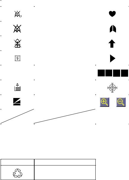
On screen
Symbol |
Description |
Symbol |
Description |
||
|
|
|
|
|
|
|
Alarm suspend with remaining |
|
|
|
QRS/pulse sync mark |
|
minutes |
|
|
|
|
|
|
|
|
|
|
|
|
|
|
|
|
|
Alarm off |
|
|
|
Respiration sync mark |
|
|
|
|
|
|
|
Alarm recording off |
|
|
|
Value out of range |
|
|
|
|
||
|
|
|
|
|
|
|
Recording |
|
|
|
Current setting |
|
|
|
|
|
|
|
Paper magazine open |
|
|
|
Adjust setting |
|
|
|
|
|
|
|
Out of paper |
|
|
|
Touch screen calibration mark |
|
|
|
|
|
|
|
Function key |
|
|
|
Change scale |
|
|
|
|
|
|
|
|
|
|
|
Network communicating |
|
|
|
|
|
|
Others
Symbol |
Description |
Recycle (On battery pack)
vi |
Service Manual BSM-4100 |
Section 1 General
Introduction ......................................................................................................................... |
1.1 |
General Information on Servicing ........................................................................................ |
1.2 |
Service Policy, Service Parts and Patient Safety Checks ................................................... |
1.4 |
Service Policy ........................................................................................................... |
1.4 |
Service Parts ............................................................................................................ |
1.4 |
Patient Safety Checks .............................................................................................. |
1.5 |
Composition ........................................................................................................................ |
1.6 |
BSM-4101/4103/4111/4113 ....................................................................................... |
1.6 |
BSM-4102/4104/4112/4114 ....................................................................................... |
1.8 |
Specifications ................................................................................................................... |
1.10 |
Display .......................................................................................................... |
1.10 |
Sound............................................................................................................ |
1.10 |
Alarm ............................................................................................................ |
1.10 |
ECG .............................................................................................................. |
1.10 |
Respiration (Transthoracic impedance pneumography) .................................. |
1.11 |
SpO2 on BSM-4101/4103/4111/4113 Monitors .............................................. |
1.11 |
SpO2 on BSM-4102/4104/4112/4114 Monitors .............................................. |
1.12 |
Non Invasive Blood pressure, NIBP .............................................................. |
1.12 |
Invasive Blood Pressure, IBP ....................................................................... |
1.13 |
Temperature .................................................................................................. |
1.13 |
Cardiac Output, CO ....................................................................................... |
1.13 |
Respiration (Thermistor method) ................................................................... |
1.14 |
Inspired Oxygen Fractional Concentration, FiO2 ............................................ |
1.14 |
Expired Carbon Dioxide Tension, CO2 ............................................................ |
1.14 |
Trendgraph .................................................................................................... |
1.15 |
Vital Signs List .............................................................................................. |
1.15 |
Hemodynamics List (BSM-4103/4104/4113/4114 monitors only) .................. |
1.15 |
Full Disclosure (QM-421P flash memory card required) ................................ |
1.15 |
ECG/BP Output ............................................................................................ |
1.15 |
Recorder (BSM-4101/4102/4103/4104 monitors only) ................................... |
1.15 |
External Output ............................................................................................. |
1.16 |
Power Requirement ....................................................................................... |
1.16 |
Environment .................................................................................................. |
1.16 |
Dimensions and Weight (approximate) .......................................................... |
1.16 |
Service Manual BSM-4100 |
1C.1 |
Electromagnetic Compatibility ....................................................................... |
1.16 |
Safety Standard ............................................................................................ |
1.16 |
Names and Function of Parts ............................................................................................ |
1.18 |
Front Panel .............................................................................................................. |
1.18 |
Socket Panel ........................................................................................................... |
1.20 |
On the BSM-4101/4103/4111/4113 Monitors ................................................. |
1.20 |
On the BSM-4102/4104/4112/4114 Monitors ................................................. |
1.20 |
Using the Output Signal from the ECG/BP OUT Socket ............................... |
1.21 |
Using Multi-parameter Sockets for CO and CO2 Monitoring ........................... |
1.21 |
Left Side Panel ........................................................................................................ |
1.22 |
Right Side Panel ...................................................................................................... |
1.22 |
Storage and Transport ....................................................................................................... |
1.23 |
Storage .................................................................................................................... |
1.23 |
Transport ................................................................................................................. |
1.23 |
Hard Keys and Soft Keys .................................................................................................. |
1.24 |
Hard Keys ............................................................................................................... |
1.24 |
Soft Keys ................................................................................................................ |
1.24 |
Upgrading the System Software and Changing Language on the Screen .......................... |
1.25 |
Procedure ..................................................................................................... |
1.25 |
Board/Unit Connection Diagram ........................................................................................ |
1.26 |
Block Diagram ................................................................................................................... |
1.27 |
1C.2 |
Service Manual BSM-4100 |

1. GENERAL
Introduction
This service manual provides useful information to qualified personnel to understand, troubleshoot, service, maintain and repair the BSM-4100A/J/K Bedside Monitor (referred to as “the instrument” in this service manual).
All replaceable parts or units of this instrument are clearly listed with exploded illustrations to help you locate the parts quickly.
The “Maintenance” section in this service manual describes the maintenance that should be performed by qualified service personnel. The “Maintenance” section in the operator’s manual describes the maintenance that can be performed by the user.
The information in the operator’s manual is primarily for the user. However, it is important for service personnel to thoroughly read the operator’s manual and service manual before starting to troubleshoot, service, maintain or repair this instrument. This is because service personnel need to understand the operation of the instrument in order to effectively use the information in the service manual.
Service Manual BSM-4100 |
1.1 |

1. GENERAL
General Information on Servicing
Note the following information when servicing the instrument.
CAUTION
Safety
•There is the possibility that the outside surface of the instrument, such as the operation keys, could be contaminated by contagious germs, so disinfect and clean the instrument before servicing it.
When servicing the instrument, wear rubber gloves to protect yourself from infection.
•There is the possibility that when the lithium battery is broken, a solvent or toxic substance inside the lithium battery could leak out. If the solvent or toxic substance touches your skin or gets into your eye or mouth, immediately wash it with a lot of water and see a physician.
Liquid ingress
The instrument is not drip-proof, so do not install the instrument where water or liquid can get into or fall on the instrument. If liquid accidentally gets into the instrument or the instrument accidentally drops into liquid, disassemble the instrument, clean it with clean water and dry it completely. After reassembling, use the patient safety checks and function/performance checks to verify that there is nothing wrong. If there is something wrong with the instrument, contact your Nihon Kohden representative for repair.
Environmental Safeguards
Depending on the local laws in your community, it may be illegal to dispose of the lithium battery and CRT unit in the regular waste collection. Check with your local officials for proper disposal procedures.
Disinfection and cleaning
To disinfect the outside surface of the instrument, wipe it with a nonabrasive cloth moistened with any of the disinfectants listed below. Do not use any other disinfectants or ultraviolet rays to disinfect the
instrument. |
|
- Chlorohexidine gluconate solution: |
0.5% |
- Benzethonium chloride solution: |
0.2% |
- Glutaraldehyde solution: |
2.0% |
- Benzalkonium chloride: |
0.2% |
- Hydrochloric alkyl diaminoethylglycine: |
0.5% |
1.2 |
Service Manual BSM-4100 |

1. GENERAL
Transport
•Use the specified shipment container and packing material to transport the instrument. If necessary, double pack the instrument. Also, put the instrument into the shipment container after packing so that the buffer material does not get inside the instrument.
•When transporting a board or unit of the instrument, be sure to use a conductive bag. Never use an aluminum bag when transporting the power board, power unit or board on which a lithium battery is mounted. Also, never wrap the board or unit of the instrument with styrene foam or a plastic bag which generates static electricity.
Handling the instrument
•Because the outside surface of the instrument is made of resin, it is easily damaged. When handling the instrument, remove clutter from around the instrument and be careful not to damage the instrument or get it dirty.
•Because most of the boards in the instrument are multilayer boards with surface mounted electrical devices (SMD), a special tool is required when removing and soldering the electrical devices. To avoid damaging other electrical components, do not remove and solder SMD components yourself.
Measuring and Test Equipment
Maintain the accuracy of the measuring and test equipment by checking and calibrating it according to the check and calibration procedures.
Service Manual BSM-4100 |
1.3 |

1. GENERAL
Service Policy, Service Parts and Patient Safety Checks
Service Policy
Our technical service policy for this instrument is to replace the faulty unit, board or part or damaged mechanical part with a new one. Do not perform electrical device or component level repair of the multilayer board or unit. We do not support component level repair outside the factory for the following reasons:
•Most of the boards are multilayer boards with surface mounted electrical devices, so the mounting density of the board is too high.
•A special tool and special repair skill is required to repair the multilayer boards with surface mounted electrical devices.
Disassemble the instrument or replace a board or unit in an environment where the instrument is protected against static electricity.
As background knowledge for repair, pay special attention to the following:
•You can reduce the repair time by considering the problem before starting repair.
•You can clarify the source of most of the troubles using the information from the diagnostic check function of the instrument. Refer to “Diagnostic Check “ of this manual.
Service Parts
Refer to “Replaceable Parts List” of this manual for the service parts for technical service that we provide.
NOTE
When ordering parts or accessories from your Nihon Kohden representative, please quote the NK code number and part name which is listed in this service manual, and the name or model of the unit in which the required part is located. This will help us to promptly attend to your needs. Always use parts and accessories recommended or supplied by Nihon Kohden Corporation to assure maximum performance from your instrument.
1.4 |
Service Manual BSM-4100 |
Patient Safety Checks
1. GENERAL
Periodic maintenance procedures and diagnostic check procedures are provided in this manual to ensure that the instrument is operating in accordance with its design and production specifications. To verify that the instrument is working in a safe manner with regard to patient safety, patient safety checks should be performed on the instrument before it is first installed, periodically after installation, and after any repair is made on the instrument.
For patient safety checks, perform the following checks as described in the International Electrotechnical Commission’s standard, IEC60601-1 (1988):
•Protective earth resistance check
•Earth leakage current check
•Enclosure leakage current check
•Patient leakage current check
•Withstanding voltage check
Service Manual BSM-4100 |
1.5 |
1. GENERAL
Composition
BSM-4101/4103/4111/4113
BSM-4101A
BSM-4101J
BSM-4101K
BSM-4111A
BSM-4111J
BSM-4111K
BSM-4103A
BSM-4103J
BSM-4103K
BSM-4113A
BSM-4113J
BSM-4113K
CD-225P
 RG-921P
 UR-3586
 UR-3563
 UR-3566

 UR-3541
 UR-35421
 UR-35431
 UR-3544
 UR-3546
 UR-3547
UR-3548
 UR-3561

 UR-3564

 UR-3567

 UR-3557

 UR-3558
 UR-3559

 UR-35591

 SC-039R
Chassis
Recorder Unit (BSM-4101/4103)
MAIN Board
DPU Board
Motherboard
Connection Board
Power SW Board
Operation Board
Function Dial Board
ECG RESP1 Board
ECG RESP2 Board
ECG RESP3 Board
NK SPO2 Board
NIBP Measure Board
NIBP Safety Board
MP1 Board
MP2 Board
MP3 Board (BSM-4103/4113)
MP3 Dummy Board (BSM-4101/4111)
Power Supply Block
1.6 |
Service Manual BSM-4100 |
1. GENERAL
|
|
|
|
Operation Panel |
|
|
|
YS-024R0 |
|
|
|
|
||
|
|
|
|
Input Panel (BSM-4101/4111) |
|
|
|
|
|
|
|
|
YS-024R1 |
|
|
|
|
||
|
|
|
|
Input Panel (BSM-4103/4113) |
|
|
|
|
|
|
|
|
YS-024R3 |
|
|
|
|
||
|
|
|
|
Flash Disk Card (Option) |
|
|
|
|
|
|
|
|
|
|
|
|
|
|
|
|
|
|
|
|
|
|
|
QM-421P |
|
|
|
|
||
|
|
|
|
Transmitter (Option) |
|
|
|
|
|
|
|
|
|
|
|
|
|
|
|
|
|
|
ZB-800PA |
|
|
|
|
||
|
|
|
||
|
|
|
|
Transmitter (Option) |
|
|
|
|
|
|
|
|
|
|
|
|
|
ZB-800PG |
|
|
|
|
||
|
|
|
|
Transmitter (Option) |
|
|
|
|
|
|
|
|
|
|
|
|
|
|
|
|
|
|
ZB-800PK |
|
|
|
|
||
|
|
|
|
Network Card (Option) |
|
|
|
|
|
|
|
|
|
|
|
|
|
|
|
|
|
|
QI-101P |
|
|
|
|
||
|
|
|
||
|
|
|
|
Network Printer Card (Option) |
|
|
|
|
|
|
|
|
|
|
|
|
|
|
|
|
|
|
QI-111P |
|
|
|
|
||
|
|
|
|
|
Service Manual BSM-4100 |
1.7 |
1. GENERAL
BSM-4102/4104/4112/4114
BSM-4102A
BSM-4102J
BSM-4102K
BSM-4112A
BSM-4112J
BSM-4112K
BSM-4104A
BSM-4104J
BSM-4104K
BSM-4114A
BSM-4114J
BSM-4114K
CD-226P
 RG-921P
 UR-3586

 UR-35631

 UR-35661

 UR-3541

 UR-35421
 UR-35431
 UR-3544

 UR-3546

 UR-3547
 UR-3548
 UR-35611
 UR-3564
 UR-3567
 UR-3557
 UR-3558
 UR-35592
 UR-35593
 SC-039R
Chassis
Recorder Unit (BSM-4102/4104)
MAIN Board
DPU Board
Motherboard
Connection Board
Power SW Board
Operation Board
Function Dial Board
ECG RESP1 Board
ECG RESP2 Board
ECG RESP3 Board
NL SPO2 Dummy Board
NIBP Measure Board
NIBP Safety Board
MP1 Board
MP2 Board
MP3 Board (BSM-4104/4114)
MP3 Dummy Board (BSM-4102/4112)
Power Supply Block
1.8 |
Service Manual BSM-4100 |
1. GENERAL
|
|
|
|
|
|
Operation Panel |
|
|
|
|
|
YS-024R0 |
|
|
|
|
|
|
||
|
|
|
|
|
|
Input Panel (BSM-4102/4112) |
|
|
|
|
|
|
|
|
|
|
|
|
YS-024R2 |
|
|
|
|
|
|
||
|
|
|
|
|
|
Input Panel (BSM-4104/4114) |
|
|
|
|
|
|
|
|
|
|
|
|
YZ-024R4 |
|
|
|
|
|
|
||
|
|
|
|
|
|
Flash Disk Card (Option) |
|
|
|
|
|
|
|
|
|
|
|
|
|
|
|
|
|
|
|
|
|
|
|
|
|
|
QM-421P |
|
|
|
|
|
|
||
|
|
|
|
|
||
|
|
|
|
|
|
Transmitter (Option) |
|
|
|
|
|
|
|
|
|
|
|
|
|
|
|
|
|
|
|
ZB-800PA |
|
|
|
|
|
|
||
|
|
|
|
|
|
Transmitter (Option) |
|
|
|
|
|
|
|
|
|
|
|
|
|
|
|
|
|
|
|
ZB-800PG |
|
|
|
|
|
|
||
|
|
|
|
|
|
Transmitter (Option) |
|
|
|
|
|
|
|
|
|
|
|
|
|
|
|
|
|
|
|
|
|
|
|
|
|
|
ZB-800PK |
|
|
|
|
|
|
||
|
|
|
|
|
|
Network Card (Option) |
|
|
|
|
|
|
|
|
|
|
|
|
|
|
|
|
|
|
|
|
|
|
|
|
|
|
QI-101P |
|
|
|
|
|
|
||
|
|
|
|
|
|
Network Printer Card (Option) |
|
|
|
|
|
|
|
|
|
|
|
|
|
|
|
|
|
|
|
|
|
|
|
|
|
|
QI-111P |
|
|
|
|
|
|
||
|
|
|
|
|
|
|
Service Manual BSM-4100 |
1.9 |

1. GENERAL
Specifications
Display |
|
Display size: |
12.1 inch, TFT type LCD |
Waveform display mode: |
Non-fade moving or non-fade fixed |
Viewing area: |
246 mm × 184.5 mm |
Resolution: |
800 × 600 dots |
Maximum number of waveform trace: |
13 traces (12 lead display) |
Sweep speed: |
25 mm/s, 50 mm/s (At compressed: 6.25 mm/s, Respiration low speed: 1.56 mm/s) |
Sweep time: |
7.4 s (at 25 mm/s sweep speed) |
Waveform display color: |
12 |
Numeric display color: |
12 |
Waveform freeze: |
Provided |
Display waveforms: |
ECG, respiration, IBP, SpO2 pulse wave, CO2 and CO thermodilution curve |
Numerical data display: |
Heart rate, VPC rate, ST level, respiration rate, IBP (systolic, diastolic, mean), |
|
NIBP (systolic, diastolic, mean), SpO2, pulse rate, temperature, CO, FiO2, ETCO2 |
Synchronization mark: |
Heart rate sync mark, pulse rate sync mark, respiratory sync mark |
Sound |
|
Sound type: |
Alarm, synchronization, click |
Alarm sound: |
3 types |
Synchronization sound: |
Pitch variable for IBP and SpO2 |
Alarm |
|
Alarm items: |
Upper/lower limits alarm, apnea alarm, arrhythmia alarm, connector disconnection |
|
alarm, NOISE alarm, electrode off alarm, waveform detecting alarm, probe off |
|
alarm, cuff/hose check alarm, sensor check alarm, low battery alarm, operating |
|
environment alarm |
Alarm types: |
Crisis (red blinking), Warning (yellow blinking), Advisory (yellow lighting), |
|
Message |
Alarm indication: |
Alarm indicator, highlighted message, alarm sound |
Alarm suspend: |
Provided (for 1 or 2 min) |
ECG |
|
Electrode offset potential tolerance: |
±500 mV |
Input dynamic range: |
± 5 mV |
Internal noise: |
≤20 µVp-p (Refer to input) |
Common mode rejection ration: |
≥90 dB |
Input impedance |
≥5 MΩ (at 10 Hz) |
Input bias current: |
≤100 nA |
Heart rate count |
|
Calculation method: |
Moving average/Instantaneous beat to beat (selectable) |
Counting range: |
0, 12 to 300 beats/min (±2 beats/min) |
Arrhythmia analysis |
|
Analysis method: |
Template matching method |
Number of channels: |
1 channel |
VPC counting rate: |
0 to 99 VPCs/min |
1.10 |
Service Manual BSM-4100 |
|
1. GENERAL |
Arrhythmia message: |
ASYSTOLE, VT, VF, VPC RUN, COUPLET, EARLY VPC, BIGEMINY, FREQ |
|
VPC, TACHYCARDIA, BRADYCARDIA, NOISE, Electrode OFF, LEARNING |
Arrhythmia recall: |
|
Number of recall files: |
16 |
Storage time per file: |
8 s |
ST level measurement: |
|
Number of measurement channels:3-electrodes: 1 ch |
|
|
6-electrodes: 8 ch |
|
10-electrodes: 12 ch |
Measuring range: |
±2.5 mV |
Pacemaker pulse rejection capability: |
0.1 to 2 ms, ±2 to 700 mV |
|
ANSI/AAMI EC 13-1992 compatible |
|
Pacing pulse detection ON/OFF |
Defibrillation-proof: |
ECG input protected against 400 J |
|
IEC 60601-2-27 17.101 compatible |
ESU interference filter: |
Provided |
AC hum filter: |
OFF: 150 ±10 Hz (> −3 dB) |
|
ON: 23 ±3 Hz (> −3 dB) |
|
≤ −16 dB (50 Hz or 60 Hz) |
Lead: |
|
3-electrode cable: |
I, II, III |
6-electrode cable: |
I, II, III, aVR, aVL, aVF, 2 from V1 to V6 |
10-electrode cable: |
I, II, III, aVR, aVL, aVF, V1 to V6 |
Waveform display: |
|
Display sensitivity: |
10 mm/mV ±5% (at ×1 sensitivity) |
Sensitivity control: |
×1/4, ×1/2, ×1, ×2, ×4, or AUTO |
Auto positioning: |
Available |
Pacing spike display: |
Available |
Heart rate display update cycle: |
Every 3 s or when alarm is generated |
Alarm items: |
|
Upper limit range: |
20 to 300 beats/min in 5 beats/min steps, OFF |
Lower limit range: |
OFF, 15 to 295 beats/min in 5 beats/min steps |
Alarm items: |
TACHYCARDIA, BRADYCARDIA, ASYSTOLE |
Respiration (Transthoracic impedance pneumography) |
|
Measuring impedance available range: |
0 to 2 kΩ |
Internal noise: |
≤0.2 Ω (Refer to input) |
Excitor current: |
30 ±10 µArms at 31.25 kHz |
Frequency response: |
0.1 to 3.2 Hz ±1 Hz (−3 dB) |
Respiration counter counting range: |
0 to 150 breaths/min |
Defibrillation proof: |
Respiration input protected against 400 J discharge |
Waveform display: |
|
Display sensitivity: |
10 mm/Ω ±25% (at ×1 sensitivity) |
Sensitivity control: |
×1/4, ×1/2, ×1, ×2, ×4 |
Respiration rate display update cycle: |
Every 3 s or when alarm is generated |
Alarm: |
|
Upper limit range: |
2 to 150 breaths/min in 2 breaths/min steps, OFF |
Lower limit range: |
OFF, 0 to 148 breaths/min in 2 steps |
Apnea time: |
OFF, 5 to 40 s in 5 s steps |
Service Manual BSM-4100 |
1.11 |
1. GENERAL
SpO2 on BSM-4101/4103/4111/4113 Monitors
Measuring range: |
50 to 100% |
SpO2 accuracy: |
±2 digits (80% ≤ SpO2 ≤ 100%) |
|
±3 digits (50% ≤ SpO2 < 80%) |
SpO2 display: |
|
Pulse rate display update cycle: |
Every 3 s or when alarm is generated |
Sync tone modulation: |
Change in 20 steps at 81 to 100% SpO2 |
Waveform sensitivity: |
×1/8, ×1/4, ×1/2, ×1, ×2, ×4, ×8 |
Alarm: |
|
Upper limit range: |
51 to 100% SpO2 in 1% SpO2 steps, OFF |
Lower limit range: |
OFF, 50 to 99% SpO2 in 1% SpO2 steps |
SpO2 on BSM-4102/4104/4112/4114 Monitors
Measuring range:
SpO2 accuracy:
SpO2 display:
Pulse rate display update cycle: Sync tone modulation:
Waveform sensitivity:
Alarm:
Upper limit range:
Lower limit range:
Non Invasive Blood pressure, NIBP
Measuring method:
Cuff pressure display range:
Accuracy:
1 to 100% |
|
DS-100A: |
±3% SpO2 |
OXIBAND A/N: ±3% SpO2 |
|
OXIBAND P/I: ±3% SpO2 |
|
RS-10: |
±3.5% SpO2 |
D-YS: |
±3% SpO2 |
D-YSE: |
±3.5% SpO2 |
D-YSPD: |
±3.5% SpO2 |
D-25/D-25L: |
±2% SpO2 |
N-25: |
±2% SpO2 |
I-20: |
±2% SpO2 |
D-20: |
±2% SpO2 |
R-15: |
±3.5% SpO2 |
OXICLIQ I: |
±2.5% SpO2 |
OXICLIQ P: |
±2.5% SpO2 |
OXICLIQ A: |
±2.5% SpO2 |
OXICLIQ N: |
±2.5% SpO2 |
OXI1-2-3 A/N: |
±2.5% SpO2 |
OXI1-2-3 P/I: |
±2.5% SpO2 |
Every 3 s or when alarm is generated Change in 20 steps at 81 to 100% SpO2
×1/8, ×1/4, ×1/2, ×1, ×2, ×4, ×8
51 to 100% SpO2 in 1% SpO2 steps, OFF OFF, 50 to 99% SpO2 in 1% SpO2 steps
Oscillometric 0 to 300 mmHg
±3 mmHg (0 mmHg ≤ NIBP ≤ 200 mmHg) ±4 mmHg (200 mmHg ≤ NIBP ≤ 300 mmHg)
Safety:
Maximum pressurization value cuff inflation limiter: Adult 300 to 330 mmHg
Neonates 150 to 165 mmHg
Cull inflation time limiter: Adult 161 to 165 s
Neonates 81 to 84 s
1.12 |
Service Manual BSM-4100 |
|
1. GENERAL |
Measurement mode: |
Manual |
|
Continuous |
|
Periodic: 2, 2.5, 5, 10, 15, 30 min, 1, 2, 4, 8 hr interval |
NIBP data display update cycle: |
Updated every measurement |
Measurement end sound: |
Generated when measurement ends |
Alarm: |
|
Upper limit range: |
15 to 260 mmHg in 5 mmHg steps, OFF |
Lower limit range: |
OFF, 10 to 255 mmHg in 5 mmHg steps |
Invasive Blood Pressure, IBP |
|
Measuring range: |
−50 to 300 mmHg |
Measuring accuracy: |
±1 mmHg ±1 digit (−50 mmHg ≤ IBP < 100 mmHg) |
|
±1% ±1 digit (100 mmHg ≤ IBP ≤ 300 mmHg) |
Auto zero balancing range: |
±200 mmHg |
Auto zero balancing accuracy: |
±1 mmHg |
Transducer sensitivity: |
50 µV/V/10 mmHg |
Pulse rate counting range: |
0, 12 to 300 beats/min |
Pulse rate counting accuracy: |
±2 beats/min |
Noise: |
Within ±1 mmHg |
Temperature zero drift: |
±0.1 mmHg/1°C |
Frequency response: |
DC to 20 Hz ±3Hz |
Display update cycle: |
Every 3 or when alarm is generated |
BP sync sound: |
Provided, systolic value 20 to 120 mmHg, changes in 20 steps every 5 mmHg |
Alarm: |
|
Upper limit range: |
2 to 300 mmHg in 2 mmHg steps, OFF |
Lower limit range: |
OFF, 0 to 298 mmHg steps in 2 mmHg steps |
Temperature |
|
Measuring range: |
0 to 45°C |
Measuring accuracy: |
±0.1°C (25°C ≤ Temp ≤ 45°C) |
|
±0.2°C ( 0°C ≤ Temp < 25°C) |
Temperature drift: |
within ±0.005°C /°C |
Temperature range: |
|
Display range: |
0°C to 45°C (32 to 115°F) |
Display update cycle: |
Every 3 s |
Alarm: |
|
Upper limit range: |
0.1 to 45°C (32 to 113°F) in 0.1°C (1°F) steps, OFF |
Lower limit range: |
OFF, 0 to 44.9°C (31 to 112°F) in 0.1°C (1°F) steps |
Cardiac Output, CO |
|
Measuring method: |
Thermodilution method |
Measuring range: |
|
Injectate temperature (Ti): |
0°C to 27°C |
Blood temperature (Tb): |
15°C to 45°C |
Thermodilution curve (delta Tb): 0°C to 2.5°C |
|
Cardiac output (CO): |
0.1 to 20 L/min |
Measuring accuracy: |
|
Ti: |
±0.2°C |
Tb 25 to 45°C: |
±0.1°C |
Service Manual BSM-4100 |
1.13 |
1. GENERAL
Tb 15 to 25°C:
CO:
Temperature drift:
Ti:
Tb:
Frequency response (delta Tb): Injectate volume range:
Respiration (Thermistor method)
Respiration rate counting range:
Accuracy:
Noise:
Frequency response:
Waveform display
Display sensitivity:
Sensitivity control:
Respiration rate display update cycle: Alarm:
Upper limit range:
Lower limit range:
Apnea time:
±0.2°C
±5%
±0.005°C /°C ±0.005°C /°C
DC to 3 Hz (−3 dB) 3, 5, 10 mL (7F)
1, 2, 3, 4, 5 mL (5F)
0 to 150 breaths/min Apnea, 5 to 40 s
±1 breath/min
Within 2.5 Ω (Refer to input) 0.1 to 3 Hz (−3 dB)
10 mm/100 Ω ±10% (at ×1 sensitivity)
×1/4, ×1/2, ×1, ×2, ×4
Every 3 or when alarm is generated
2 to 150 breaths/min in 2 breaths/min steps, OFF OFF, 0 to 148 breaths/min in 2 breaths/min OFF, 5 to 40 s in 5 s steps
Inspired Oxygen Fractional Concentration, FiO2
Measuring range: |
10 to 100% O2 |
Accuracy: |
±3% full scale (When calibrated at 21% O2) |
|
±2% full scale (When calibrated at 100% O2) |
Temperature drift: |
±0.12% O2/°C |
FiO2 display update cycle: |
Every 3 s or when alarm is generated |
Alarm: |
|
Upper limit range: |
19 to 100% in 1% steps, OFF |
Upper limit range: |
OFF, 18 to 99% in 1% steps |
Expired Carbon Dioxide Tension, CO2 |
|
Measuring method: |
Mainstream (TG-900P) |
Measuring range: |
|
TG-900P: |
0 to 99 mmHg |
Warm-up time: |
5 s (min) |
Response time |
|
TG-900P: |
200 ms (typical) for steps from 10 to 90% |
Detectable respiration rate |
|
Mainstream: |
3 to 60 breaths/min |
Measuring accuracy: |
|
TG-900P: |
±4 mmHg (0 ≤ CO2 ≤ 40 mmHg) |
|
±10% reading (40 < CO2 ≤ 76 mmHg) |
|
(When 1 atmospheric pressure, air inspiration, no condensation) |
CO2 value display update cycle: |
Every 3 s or when alarm is generated |
Alarm: |
|
Upper limit range: |
2 to 99 mmHg in 1 mmHg in 1 steps, OFF |
1.14 |
Service Manual BSM-4100 |
 Loading...