


Nihon Kohden BSM-6000 User manual
Administrator’s Guide
Bedside Monitor
BSM-6301/BSM-6501/BSM-6701
BSM-6000 series
BSM-6301A
BSM-6301K
BSM-6501A
BSM-6501K
BSM-6701A
BSM-6701K
0614-901238G

If you have any comments or suggestions on this manual, please contact us at: www.nihonkohden.com
Copyright Notice
The entire contents of this manual are copyrighted by Nihon Kohden. All rights are reserved. No part of this document may be reproduced, stored, or transmitted in any form or by any means (electronic, mechanical, photocopied, recorded, or otherwise) without the prior written permission of Nihon Kohden.
Trademark
The mark printed on the SD card that is used in this instrument is a trademark. The company name and model name are trademarks and registered trademarks of each company.

Contents
|
GENERAL HANDLING PRECAUTIONS.............................................................................. |
i |
|
WARRANTY POLICY.......................................................................................................... |
ii |
|
EMC RELATED CAUTION .................................................................................................. |
iii |
|
Conventions Used in this Manual and Instrument .............................................................. |
v |
|
Warnings, Cautions and Notes ................................................................................. |
v |
|
Related Documentation....................................................................................................... |
v |
|
Safety Standards................................................................................................................ |
vi |
Section 1 |
Installation/Connection......................................................... |
1.1 |
|
Installation Conditions....................................................................................................... |
1.2 |
|
Optional Cart for the Bedside Monitor.................................................................... |
1.3 |
|
Optional Wall Mount Kit for the Bedside Monitor.................................................... |
1.3 |
|
Installation Flowchart........................................................................................................ |
1.4 |
|
Installing the Optional Units to the Monitor and Connecting External Instruments........... |
1.5 |
|
Connection Overview............................................................................................. |
1.8 |
|
Attaching the AA-672P or AA-674P Smart Expansion Unit to the AY series |
|
|
Input Unit................................................................................................................ |
1.9 |
|
Mounting the AY series Input Unit onto the Monitor............................................... |
1.9 |
|
Using an Optional Handle.......................................................................... |
1.10 |
|
Attaching the ZS-900P Transmitter....................................................................... |
1.10 |
|
Installing the WS-671P Recorder Module............................................................. |
1.11 |
|
Installing the QI-631P, QI-632P, QI-634P, QI-671P or QI-672P Interface............. |
1.11 |
|
Connecting the Mouse.......................................................................................... |
1.12 |
|
Connecting the Bar Code Reader........................................................................ |
1.12 |
|
Connecting the JA-690PA or JA-694PA Data Acquisition Unit............................. |
1.13 |
|
Connecting External Instruments......................................................................... |
1.14 |
|
Connecting a GF-110PA or GF-210R Multigas Unit, GF-120PA or |
|
|
GF-220R Multigas/Flow Unit or AE-918P Neuro Unit................................ |
1.14 |
|
Connecting an External Instrument Using a QF Series Interface or IF |
|
|
Series Communication Cable..................................................................... |
1.15 |
|
Connecting a Sub Display.................................................................................... |
1.15 |
|
Connecting the Power Cord and Grounding Lead.......................................................... |
1.17 |
|
General................................................................................................................. |
1.17 |
|
Connecting the Power Cord.................................................................................. |
1.17 |
|
Grounding the Monitor.......................................................................................... |
1.18 |
|
Connecting the Monitor to the Network.......................................................................... |
1.19 |
|
Connecting the QW-100Y (HIT-100) Hyper Isolation Transformer........................ |
1.20 |
|
Connecting the QI-320PA Wireless LAN Station.................................................. |
1.20 |
|
Turning the Power On/Off............................................................................................... |
1.21 |
|
Check Before Turning On the Power..................................................................... |
1.21 |
|
Turning the Power On........................................................................................... |
1.21 |
|
Check After Turning On the Power and During Monitoring................................... |
1.22 |
|
Monitor Status on Power Interruption................................................................... |
1.23 |
|
Turning the Power Off........................................................................................... |
1.23 |
1
2
3
4
Administrator’s Guide BSM-6000 |
C.1 |
CONTENTS |
|
Check After and Before Turning the Power Off..................................................... |
1.24 |
Setting the Bar Code Reader.......................................................................................... |
1.25 |
Scanning the Bar Code Reader Settings.............................................................. |
1.25 |
Initializing the Bar Code Reader........................................................................... |
1.26 |
Checking the Bar Code Reader Operation........................................................... |
1.26 |
Calibrating the Touch Screen.......................................................................................... |
1.27 |
Using ECG/BP Output as the Synchronous Signal........................................................ |
1.28 |
Section 2 Changing SYSTEM CONFIGURATION Screen Settings..... |
2.1 |
Overview........................................................................................................................... |
2.2 |
Setting Items on the SYSTEM CONFIGURATION Screen..................................... |
2.2 |
Displaying the SYSTEM CONFIGURATION Screen.............................................. |
2.3 |
Closing the SYSTEM CONFIGURATION Screen................................................... |
2.5 |
SITE Window.................................................................................................................... |
2.6 |
NETWORK Window.......................................................................................................... |
2.7 |
UNITS Window................................................................................................................. |
2.8 |
TRANSPORT Window...................................................................................................... |
2.9 |
PC Window..................................................................................................................... |
2.11 |
CHANGE PASSWORD Window..................................................................................... |
2.12 |
OTHER Window.............................................................................................................. |
2.13 |
Initializing the Monitor..................................................................................................... |
2.14 |
Section 3 |
Changing SYSTEM SETUP Window Settings...................... |
3.1 |
|
Overview........................................................................................................................... |
3.3 |
|
Setting Items on the SYSTEM SETUP Window..................................................... |
3.3 |
|
Displaying the SYSTEM SETUP Window............................................................... |
3.8 |
|
Closing the SYSTEM SETUP Window................................................................... |
3.9 |
|
The INFO Page of the INFO Window................................................................... |
3.10 |
|
The CONFIGURATION Page of the INFO Window.............................................. |
3.10 |
|
The MAINTENANCE Page of the INFO Window.................................................. |
3.11 |
|
BATTERY Tab............................................................................................. |
3.11 |
|
LOAD/SAVE SETTINGS Tab...................................................................... |
3.11 |
|
SYSTEM Window........................................................................................................... |
3.12 |
|
DISPLAY Page..................................................................................................... |
3.12 |
|
LAYOUT Page....................................................................................................... |
3.13 |
|
VOLUME Page..................................................................................................... |
3.15 |
|
BED ID Window.............................................................................................................. |
3.17 |
|
PARAMETERS Window.................................................................................................. |
3.18 |
|
ECG Page............................................................................................................. |
3.18 |
|
NIBP Page............................................................................................................ |
3.20 |
|
NIBP MODE Page................................................................................................ |
3.21 |
|
STAT Tab.................................................................................................... |
3.21 |
|
SIM Tab...................................................................................................... |
3.21 |
|
INTERVAL Tab............................................................................................ |
3.22 |
|
VENOUS PUNCTURE Tab......................................................................... |
3.23 |
|
INITIAL CUFF PRESS Tab......................................................................... |
3.23 |
|
CO2 Page.............................................................................................................. |
3.24 |
C.2 |
Administrator’s Guide |
BSM-6000 |

|
CONTENTS |
|
|
GAS Page............................................................................................................. |
3.24 |
|
MAINTENANCE Tab................................................................................... |
3.24 |
|
SETTINGS Tab........................................................................................... |
3.25 |
|
INFO Tab.................................................................................................... |
3.26 |
|
FLOW/Paw Page.................................................................................................. |
3.26 |
|
CAL Tab...................................................................................................... |
3.26 |
|
SETTINGS Tab........................................................................................... |
3.27 |
|
MAINTENANCE Tab................................................................................... |
3.27 |
|
INFO Tab.................................................................................................... |
3.28 |
|
EEG Page............................................................................................................. |
3.28 |
|
OTHER PARAM Page........................................................................................... |
3.29 |
|
ALARM Window.............................................................................................................. |
3.31 |
|
SILENCE/SUSPEND Page................................................................................... |
3.31 |
|
DISPLAY/SOUND Page....................................................................................... |
3.33 |
|
ALARM PRIORITY Page...................................................................................... |
3.34 |
|
ARRHYTH PRIORITY Page................................................................................. |
3.35 |
|
TECHNICAL PRIORITY Page.............................................................................. |
3.36 |
|
SLEEP Page......................................................................................................... |
3.37 |
|
COLOR Window............................................................................................................. |
3.38 |
|
RECORD Window........................................................................................................... |
3.40 |
|
RECORDER Page................................................................................................ |
3.40 |
|
PRINTER Page..................................................................................................... |
3.41 |
|
Using Network Printer................................................................................ |
3.42 |
|
MASTER Window........................................................................................................... |
3.45 |
|
MAIN ALARMS/ECG ALARMS/PRESS ALARMS/TEMP ALARMS/GAS |
|
|
ALARMS/OTHER ALARMS Pages...................................................................... |
3.45 |
|
ARRHYTH Page................................................................................................... |
3.46 |
|
RY-910P/MOUSE Window.............................................................................................. |
3.48 |
|
KEYS Window................................................................................................................. |
3.49 |
Section 4 |
Reference............................................................................... |
4.1 |
|
Factory Default Settings.................................................................................................... |
4.2 |
|
SYSTEM CONFIGURATION Screen...................................................................... |
4.2 |
|
SYSTEM SETUP Window...................................................................................... |
4.3 |
|
General Requirements for Connecting Medical Electrical Systems................................ |
4.15 |
|
Connector Pin Assignment............................................................................................. |
4.16 |
|
MU-631R/MU-651R/MU-671R Main Unit............................................................. |
4.16 |
|
QI-631P Interface................................................................................................. |
4.16 |
|
QI-632P Interface................................................................................................. |
4.17 |
|
QI-634P Interface................................................................................................. |
4.17 |
|
QI-671P Interface................................................................................................. |
4.18 |
|
QI-672P Interface................................................................................................. |
4.19 |
|
AY-631P/AY-633P/AY-651P/AY-653P/AY-661P/AY-663P/AY-671P/AY-673P |
|
|
Input Unit.............................................................................................................. |
4.20 |
|
Check Sheet for Unit Settings......................................................................................... |
4.21 |
1
2
3
4
Administrator’s Guide BSM-6000 |
C.3 |
GENERAL HANDLING PRECAUTIONS
This device is intended for use only by qualified medical personnel.
Use only Nihon Kohden approved products with this device. Use of non-approved products or in a non-approved manner may affect the performance specifications of the device. This includes, but is not limited to, batteries, recording paper, pens, extension cables, electrode leads, input boxes and AC power.
Please read these precautions thoroughly before attempting to operate the instrument.
1.To safely and effectively use the instrument, its operation must be fully understood.
2.When installing or storing the instrument, take the following precautions:
(1)Avoid moisture or contact with water, extreme atmospheric pressure, excessive humidity and temperatures, poorly ventilated areas, and dust, saline or sulphuric air.
(2)Place the instrument on an even, level floor. Avoid vibration and mechanical shock, even during transport.
(3)Avoid placing in an area where chemicals are stored or where there is danger of gas leakage.
(4)The power line source to be applied to the instrument must correspond in frequency and voltage to product specifications, and have sufficient current capacity.
(5)Choose a room where a proper grounding facility is available.
3.Before Operation
(1)Check that the instrument is in perfect operating order.
(2)Check that the instrument is grounded properly.
(3)Check that all cords are connected properly.
(4)Pay extra attention when the instrument is combined with other instruments to avoid misdiagnosis or other problems.
(5)All circuitry used for direct patient connection must be doubly checked.
(6)Check that battery level is acceptable and battery condition is good when using battery-operated models.
4.During Operation
(1)Both the instrument and the patient must receive continual, careful attention.
(2)Turn power off or remove electrodes and/or transducers when necessary to assure the patient’s safety.
(3)Avoid direct contact between the instrument housing and the patient.
5.To Shutdown After Use
(1)Turn power off with all controls returned to their original positions.
(2)Remove the cords gently; do not use force to remove them.
(3)Clean the instrument together with all accessories for their next use.
6.The instrument must receive expert, professional attention for maintenance and repairs. When the instrument is not functioning properly, it should be clearly marked to avoid operation while it is out of order.
7.The instrument must not be altered or modified in any way.
8.Maintenance and Inspection
(1)The instrument and parts must undergo regular maintenance inspection at least every 6 months.
(2)If stored for extended periods without being used, make sure prior to operation that the instrument is in perfect operating condition.
Administrator’s Guide BSM-6000 |
i |

(3)Technical information such as parts list, descriptions, calibration instructions or other information is available for qualified user technical personnel upon request from your Nihon Kohden distributor.
9.When the instrument is used with an electrosurgical instrument, pay careful attention to the application and/or location of electrodes and/or transducers to avoid possible burn to the patient.
10.When the instrument is used with a defibrillator, make sure that the instrument is protected against defibrillator discharge. If not, remove patient cables and/or transducers from the instrument to avoid possible damage.
WARRANTY POLICY
Nihon Kohden Corporation (NKC) shall warrant its products against all defects in materials and workmanship for one year from the date of delivery. However, consumable materials such as recording paper, ink, stylus and battery are excluded from the warranty.
NKC or its authorized agents will repair or replace any products which prove to be defective during the warranty period, provided these products are used as prescribed by the operating instructions given in the operator’s and service manuals.
No other party is authorized to make any warranty or assume liability for NKC’s products. NKC will not recognize any other warranty, either implied or in writing. In addition, service, technical modification or any other product change performed by someone other than NKC or its authorized agents without prior consent of NKC may be cause for voiding this warranty.
Defective products or parts must be returned to NKC or its authorized agents, along with an explanation of the failure. Shipping costs must be pre-paid.
This warranty does not apply to products that have been modified, disassembled, reinstalled or repaired without Nihon Kohden approval or which have been subjected to neglect or accident, damage due to accident, fire, lightning, vandalism, water or other casualty, improper installation or application, or on which the original identification marks have been removed.
In the USA and Canada other warranty policies may apply.
CAUTION
United States law restricts this product to sale by or on the order of a physician.
ii |
Administrator’s Guide BSM-6000 |

EMC RELATED CAUTION
This equipment and/or system complies with IEC 60601-1-2 International Standard for electromagnetic compatibility for medical electrical equipment and/or system. However, an electromagnetic environment that exceeds the limits or levels stipulated in IEC 60601-1-2, can cause harmful interference to the equipment and/or system or cause the equipment and/or system to fail to perform its intended function or degrade its intended performance. Therefore, during the operation of the equipment and/or system, if there is any undesired deviation from its intended operational performance, you must avoid, identify and resolve the adverse electromagnetic effect before continuing to use the equipment and/or system.
The following describes some common interference sources and remedial actions:
1.Strong electromagnetic interference from a nearby emitter source such as an authorized radio station or cellular phone:
Install the equipment and/or system at another location. Keep the emitter source such as cellular phone away from the equipment and/or system, or turn off the cellular phone.
2.Radio-frequency interference from other equipment through the AC power supply of the equipment and/or system:
Identify the cause of this interference and if possible remove this interference source. If this is not possible, use a different power supply.
3.Effect of direct or indirect electrostatic discharge:
Make sure all users and patients in contact with the equipment and/or system are free from direct or indirect electrostatic energy before using it. A humid room can help lessen this problem.
4.Electromagnetic interference with any radio wave receiver such as radio or television:
If the equipment and/or system interferes with any radio wave receiver, locate the equipment and/or system as far as possible from the radio wave receiver.
5.Interference of lightning:
When lightning occurs near the location where the equipment and/or system is installed, it may induce an excessive voltage in the equipment and/or system. In such a case, disconnect the AC power cord from the equipment and/or system and operate the equipment and/or system by battery power, or use an uninterruptible power supply.
6.Use with other equipment:
When the equipment and/or system is adjacent to or stacked with other equipment, the equipment and/or system may affect the other equipment. Before use, check that the equipment and/or system operates normally with the other equipment.
7.Use of unspecified accessory, transducer and/or cable:
When an unspecified accessory, transducer and/or cable is connected to this equipment and/or system, it may cause increased electromagnetic emission or decreased electromagnetic immunity. The specified configuration of this equipment and/or system complies with the electromagnetic requirements with the specified configuration. Only use this equipment and/or system with the specified configuration.
Administrator’s Guide BSM-6000 |
iii |

Caution - continued
8.Use of unspecified configuration:
When the equipment and/or system is used with the unspecified system configuration different than the configuration of EMC testing, it may cause increased electromagnetic emission or decreased electromagnetic immunity. Only use this equipment and/or system with the specified configuration.
9.Measurement with excessive sensitivity:
The equipment and/or system is designed to measure bioelectrical signals with a specified sensitivity. If the equipment and/or system is used with excessive sensitivity, artifact may appear by electromagnetic interference and this may cause mis-diagnosis. When unexpected artifact appears, inspect the surrounding electromagnetic conditions and remove this artifact source.
If the above suggested remedial actions do not solve the problem, consult your Nihon Kohden distributor or representative for additional suggestions.
In IEC 60601-1-2 Medical Electronic Equipment, Part 1: General Requirements for Safety, 2. Collateral Standard: Electromagnetic compatibility-Requirements and test. Section 36. 202. 2 Radiated radiofrequency electromagnetic fields, PATIENT COUPLED EQUIPMENT and/or SYSTEMS applicable IMMUNITY test methods are under consideration at SC62A/WG13. The 3 V/m IMMUNITY level may be inappropriate especially when measuring SpO2 because physiological signals can be much smaller than those induced by a 3 V/m electromagnetic field.
When measuring SpO2, various interference may produce false waveforms which look like pulse waveforms. SpO2 value and pulse rate may be measured from these false waveforms, causing the alarm to function improperly.
When installing the monitor, avoid locations where the monitor may receive strong electromagnetic interference such as radio or TV stations, cellular phone or mobile two-way radios.
WARNING
Interaction Between Minute Ventilation Rate-Adaptive Pacemakers and Cardiac Monitoring and Diagnostic Equipment*
The bioelectric impedance measurement sensor of a minute ventilation rate-adaptive implantable pacemaker may be affected by cardiac monitoring and diagnostic equipment which is connected to the same patient. If this occurs, the pacemaker may pace at its maximum rate and give incorrect data to the monitor or diagnostic equipment. If this occurs, disconnect the monitor or diagnostic equipment from the patient or change the setting on the pacemaker by referring to the pacemaker’s manual. For more details, contact your pacemaker representative or Nihon Kohden representative.
*Minute ventilation is sensed in rate-adaptive pacemakers by a technology known as bioelectric impedance measurement (BIM). Many medical devices in addition to pacemakers use this technology. When one of these devices is used on a patient with an active, minute ventilation rate-adaptive pacemaker, the pacemaker may erroneously interpret the mixture of BIM signals created in the patient, resulting in an elevated pacing rate.
For more information, see the FDA web site. http://www.fda.gov/cdrh/safety.html
iv |
Administrator’s Guide BSM-6000 |

Conventions Used in this Manual and Instrument
Warnings, Cautions and Notes
Warnings, cautions and notes are used in this manual to alert or signal the reader to specific information.
WARNING
A warning alerts the user to possible injury or death associated with the use or misuse of the instrument.
CAUTION
A caution alerts the user to possible injury or problems with the instrument associated with its use or misuse such as instrument malfunction, instrument failure, damage to the instrument, or damage to other property.
NOTE
A note provides specific information, in the form of recommendations, prerequirements, alternative methods or supplemental information.
Related Documentation
The BSM-6000A/K series Bedside Monitor comes with the following manuals in addition to the Operator’s Manual.
Administrator’s Guide
Describes how to install the bedside monitor. It also explains about the password protected settings on the SYSTEM SETUP window and SYSTEM CONFIGURATION screen which only an administrator can change.
User’s Guide, Part I
Gives supplemental information on the operation of the bedside monitor.
User’s Guide, Part II
Describes the features and settings of the monitoring parameters.
Service Manual
Describes information on servicing the bedside monitor. Only qualified service personnel can service the bedside monitor.
Administrator’s Guide BSM-6000 |
v |
Safety Standards
The safety standard of this bedside monitor is classified as follows:
Type of protection against electrical shock: CLASS I EQUIPMENT (AC Powered)
Internally Powered EQUIPMENT (BATTERY Powered) Degree of protection against electrical shock
Defibrillator-proof type CF applied part
AY-631P, AY-633P, AY-651P, AY-653P, AY-661P, AY-663P, AY-671P and AY-673P:
ECG, Respiration (impedance and thermistor method), IBP, Temperature, SpO2, CO2, O2, NIBP, BIS
AY-660P: ECG, Respiration (impedance method), IBP, Temperature, SpO2, CO2, NIBP AA-672P and AA-674P: Respiration (thermistor method), IBP, Temperature, SpO2, CO2, O2, BIS
CF applied part:
AY-631P, AY-633P, AY-651P, AY-653P, AY-661P, AY-663P, AY-671P, AY-673P, AA-672P and AA-674P: CO Degree of protection against harmful ingress of water: IPX0 (non-protected)
Degree of safety of application in the presence of FLAMMABLE ANAESTHETIC MIXTURE WITH AIR, OR WITH OXYGEN OR NITROUS OXIDE:
Equipment not suitable for use in the presence of FLAMMABLE ANAESTHETIC MIXTURE WITH AIR, OR WITH OXYGEN OR NITROUS OXIDE
Mode of operation: CONTINUOUS OPERATION
vi |
Administrator’s Guide BSM-6000 |

Section 1 Installation/Connection 1
Installation Conditions................................... |
.................................... |
1.2 |
|||
Optional Cart for the Bedside Monitor................................... |
.............................. |
|
1.3 |
||
Optional Wall Mount Kit for the Bedside Monitor................................... |
.............. |
1.3 |
|||
Installation Flowchart................................... |
.................................... |
1.4 |
|||
Installing the Optional Units to the Monitor and Connecting External Instruments................................... |
1.5 |
||||
Connection Overview................................... |
|
.................................... |
1.8 |
||
Attaching the AA-672P or AA-674P Smart Expansion Unit to the AY series Input Unit............................. |
|
1.9 |
|||
Mounting the AY series Input Unit onto the Monitor................................... |
|
......... 1.9 |
|||
Using an Optional Handle................................... |
.................................... |
|
1.10 |
||
Attaching the ZS-900P Transmitter................................... |
................................. |
|
1.10 |
||
Installing the WS-671P Recorder Module................................... |
...................... |
|
1.11 |
||
Installing the QI-631P, QI-632P, QI-634P, QI-671P or QI-672P Interface................................... |
1.11 |
||||
Connecting the Mouse................................... |
|
.................................... |
1.12 |
||
Connecting the Bar Code Reader................................... |
.................................. |
|
1.12 |
||
Connecting the JA-690PA or JA-694PA Data Acquisition Unit................................... |
1.13 |
||||
Connecting External Instruments................................... |
................................... |
|
1.14 |
||
Connecting a GF-110PA or GF-210R Multigas Unit, GF-120PA or GF-220R Multigas/Flow |
|
||||
Unit or AE-918P Neuro Unit................................... |
................................. |
|
1.14 |
||
Connecting an External Instrument Using a QF Series Interface or IF Series Communication |
|||||
Cable................................... |
.................................... |
1.15 |
|||
Connecting a Sub Display................................... |
|
.................................... |
1.15 |
||
Connecting the Power Cord and Grounding Lead................................... |
.................... |
|
1.17 |
||
General.................................. |
.................................... |
1.17 |
|||
Connecting the Power Cord................................... |
|
.................................... |
|
1.17 |
|
Grounding the Monitor.................................. |
|
.................................... |
1.18 |
||
Connecting the Monitor to the Network................................... |
.................................... |
|
1.19 |
||
Connecting the QW-100Y (HIT-100) Hyper Isolation Transformer................................... |
1.20 |
||||
Connecting the QI-320PA Wireless LAN Station................................... |
............ |
1.20 |
|||
Turning the Power On/Off................................... |
|
.................................... 1.21 |
|||
Check Before Turning On the Power................................... |
.............................. |
|
1.21 |
||
Turning the Power On................................... |
|
.................................... |
1.21 |
||
Check After Turning On the Power and During Monitoring................................... |
1.22 |
||||
Monitor Status on Power Interruption................................... |
............................. |
|
1.23 |
||
Turning the Power Off................................... |
|
.................................... |
1.23 |
||
Check After and Before Turning the Power Off................................... |
............... |
1.24 |
|||
Setting the Bar Code Reader................................... |
|
.................................... |
1.25 |
||
Scanning the Bar Code Reader Settings................................... |
....................... |
|
1.25 |
||
Initializing the Bar Code Reader.................................. |
.................................... |
|
1.26 |
||
Checking the Bar Code Reader Operation................................... |
..................... |
|
1.26 |
||
Calibrating the Touch Screen................................... |
|
.................................... |
1.27 |
||
Using ECG/BP Output as the Synchronous Signal................................... |
.................. |
|
1.28 |
||
Administrator’s Guide BSM-6000 |
1.1 |
1. INSTALLATION/CONNECTION
This section describes installation conditions, connecting cables and power cords and check items for this bedside monitor.
For simplicity, the suffixA/G/K will be omitted in this manual. There is no difference in operation among models with different suffixes unless otherwise specified.
Installation Conditions
Note the following points for the installation location of your bedside monitor.
WARNING
•Do not install the monitor and optional units above the patient.
•Only use the specified tools or equipment when installing the monitor and units. Failure to follow this warning may result in the monitor or unit falling and injuring the patient.
CAUTION
Only use the specified stand, cart or equipment for installing the monitor and instruments. Using non-specified equipment may result in the instruments falling and causing injury.
CAUTION
When not using the specified cart, carefully set the monitor to prevent it from falling off or tipping over.
•Install the monitor where you can see the monitor screen clearly.
•Install the monitor on a strong shelf or dedicated cart (option). Secure the monitor to the shelf to prevent it from falling.
•When moving a cart with a monitor, avoid collision. Strong impact may damage the monitor.
•The monitor is not intended to be used in an ambulance. The monitor might not function properly in a moving vehicle.
•The display screen is made of glass. Strong impact may damage it.
•Avoid locations where the monitor is sprinkled with liquid. Avoid direct sprinkling, spray or moist air from a nebulizer or a humidifier.
•Avoid exposing the monitor to direct sunlight.
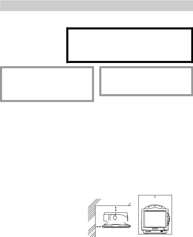
•Make sure that there is at least 5 cm of space between the monitor and the wall for adequate ventilation. When the monitor is surrounded on all sides, make sure that there is about 10 cm of space above the monitor for ventilation so that the operating temperature does not exceed 40°C (104°F).


 10 cm 5 cm Rear


 5 cm
5 cm 


 Side
Side
1.2 |
Administrator’s Guide BSM-6000 |
1. INSTALLATION/CONNECTION
• Do not cover the monitor with a blanket or cloth. It may affect monitoring. |
1 |
•Do not install the monitor in a dusty area.
•Connect the power cord to an AC outlet which can supply enough AC current to the monitor. The monitor cannot function properly with low current.
•When there is any problem on the monitor, turn off the power immediately and disconnect the power cord from the AC outlet. Take the monitor out of service and check for damage.
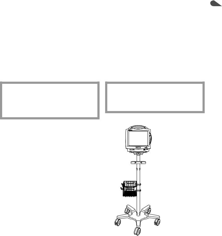
Optional Cart for the Bedside Monitor
The KC-600P cart is available for installing the monitor. For details on how to use the cart, refer to the KC-600P cart installation guide.
CAUTION
Only use the specified stand, cart or equipment for installing the monitor and instruments. Using non-specified equipment may result in the instruments falling and causing injury.
CAUTION
When not using the specified cart, carefully set the monitor to prevent it from falling off or tipping over.
Optional Wall Mount Kit for the Bedside Monitor
The KG-951P wall mount kit is available for mounting the monitor on a wall. For details on how to use the wall mount kit, refer to the KG-951P wall mount kit installation guide.
Administrator’s Guide BSM-6000 |
1.3 |

1. INSTALLATION/CONNECTION
Installation Flowchart
You may not need to do all these.
1.Install the monitor. Refer to Section 1 in this manual.
2.Prepare the battery pack, remote control and recorder. Refer to Operator’s Manual or Section 2 of the User’s Guide Part I.
3.Check or change any initial settings on the SYSTEM CONFIGURATION screen. Changing these settings during monitoring interrupts monitoring. Refer to Section 2 in this manual.
4.Check or change any initial settings on the SYSTEM SETUP window. These settings are password protected settings which only an administrator can change. Refer to Section 3 in this manual.
5.Check or change the necessary settings before monitoring. Refer to Operator’s Manual or Section 3 of the User’s Guide Part I.
•Date and time
•Sound volume
•Screen brightness
•Waveform display settings
6.Enter the information of the new patient. Refer to “Entering Patient Information” in Operator’s Manual or Section 3 of the User’s Guide Part I.
7.Check or change all alarm items for the patient. When <AUTO ADMIT> in the SYSTEM CONFIGURATION screen is set to ON, the alarm settings
return to the default settings 30 minutes after the monitor is turned off. When <AUTO ADMIT> is set to OFF, you can select whether to save the settings or initialize the master settings. Refer to Operator’s Manual or Section 5 of the User’s Guide Part I.
8.Check or change settings for the review windows, such as trendgraphs, tables and arrhythmia recall files. Refer to Operator’s Manual or Section 6 of the User’s Guide Part I.
9.Check or change recording settings. Refer to Operator’s Manual or Section 10 of the User’s Guide Part I.
10.Prepare the equipment (electrodes, transducers, probes, etc.) for monitoring individual parameters and check or change the settings for each parameter. Refer to Operator’s Manual or User’s Guide Part II.
1.4 |
Administrator’s Guide BSM-6000 |

1. INSTALLATION/CONNECTION |
|
|
|
|
1 |
Installing the Optional Units to the Monitor and Connecting |
|
|
|
|
|
External Instruments |
|
|
|
|
|
WARNING
Connect only the specified instrument to the monitor and follow the specified procedure. Failure to follow this warning may result
in electrical shock or injury to the patient and operator, and cause fire or instrument malfunction.
WARNING
When several medical instruments are used together, ground all instruments to the same onepoint ground. Any potential difference between instruments may cause electrical shock to the patient and operator.
CAUTION
Before connecting or disconnecting instruments, make sure that each instrument is turned off and the power cord is disconnected from the AC socket. Otherwise, the patient or operator may receive electrical shock or injury.
NOTE
•For details on connecting an external instrument to the monitor, contact your Nihon Kohden representative.
•Leakage current may increase when interconnecting many medical instruments to the monitor.
•Upgrade the main unit and each optional unit to the Nihon Kohden recommended software version. Only use the specified configuration of units. If more than one BSM-6000 series bedside monitor is used in the same facility, make sure the bedside monitors have the same software version. If BSM-6000 series monitors with different software versions are used together, correct system operation cannot be guaranteed.
Additional Safety Measures for Connecting External Instruments
When more than one electrical instrument is used, there may be electrical potential difference between the instruments. Potential difference between instruments may cause current to flow to the patient connected to the instruments, resulting in electrical shock (micro shock). Never use any medical equipment in patient treatment without proper grounding.
Always perform equipotential grounding as specified in IEC 60601-1-1 when required. It is often required in the operating room, ICU room, CCU room, cardiac catheterization room and X-ray room. Consult with a biomedical engineer to determine if it is required.
Refer to the reference “General Requirements for Connecting Medical Electrical
Systems” in Section 4.
Administrator’s Guide BSM-6000 |
1.5 |

1. INSTALLATION/CONNECTION
Environment for External Instruments
Use external instruments in the following environment.
When a JA-690PA/JA-694PA data acquisition unit is not connected to the bedside monitor
|
|
|
|
|
Medically-used room |
|
|
|
|
Non-medically used room |
|||||||||
|
|
|
Patient Environment |
Outside the Patient Environment |
|||||||||||||||
|
|
|
|
|
|
|
|||||||||||||
|
|
|
|
|
|
|
|
|
|
|
|
|
|
|
|
|
|
|
|
BSM-6301/6501/6701 |
|
|
|
|
|
|
|
|
|
|
|
|
|
|
|
||||
|
|
|
|
|
|
|
|
|
|
|
|
|
|
|
|
|
|
|
|
|
|
|
Interface |
|
|
|
|
|
|
|
|
|
|
|
|
|
|
|
|
|
|
|
QI-631P |
|
|
|
|
|
|
|
|
|
|
|
|
Sub display |
|
||
|
|
|
(For MU-631R) |
|
|
|
|
|
|
|
|
|
|
|
|
|
|||
|
|
|
|
|
|
|
|
|
|
|
|
|
|
|
(IEC 60601-1 complied or |
|
|||
|
|
|
|
|
|
|
|
|
|
|
|
|
|
|
|
|
|
||
|
|
|
|
|
|
|
|
|
|
|
|
|
|
|
|
|
using the isolation transformer |
|
|
|
|
|
Interface |
|
|
|
|
|
|
|
|
Sub display |
|
|
complied to IEC 60601-1) |
|
|||
|
|
|
|
|
|
|
|
|
|
|
|
|
|
|
|
||||
|
|
|
QI-671P |
|
|
|
|
|
|
|
|
(IEC 60601-1 complied or |
|
|
|
|
|
||
|
|
|
|
|
|
|
|
|
|
|
|
|
|
|
|||||
|
|
|
(For MU-651R/671R) |
|
|
|
|
|
|
|
|
using the isolation transformer |
|
|
|
|
|
||
|
|
|
|
|
|
|
|
Multigas unit |
|
complied to IEC 60601-1) |
|
|
|
|
|
||||
|
|
|
|
|
|
|
|
|
|
|
|
|
|||||||
|
|
|
|
|
|
|
|
|
|
|
|
|
|
|
|
||||
|
|
|
|
|
|
|
|
GF-110PA/210R* |
|
|
|
|
|
|
|
|
|||
|
|
|
|
|
|
|
|
|
|
|
|
|
|
|
|
||||
|
|
|
|
|
|
|
|
Multigas/Flow unit |
|
|
|
|
|
|
|
|
|||
|
|
|
|
|
|
|
|
GF-120PA*/220R* |
|
|
|
|
|
|
|
|
|||
|
|
|
|
|
|
|
|
|
|
|
|
|
|
|
|
|
|||
|
|
|
|
|
|
|
|
|
|
|
|
|
|
|
|
|
|||
|
|
|
|
|
|
|
|
Neuro unit |
|
|
|
|
|
|
|
|
|||
|
|
|
|
|
|
|
|
AE-918P* |
|
|
|
|
|
|
|
|
|||
|
|
|
|
|
|
|
|
|
|
|
|
|
|
|
|
|
|
|
|
|
|
|
Interface |
|
|
|
|
|
|
|
|
|
|
|
|
|
|
|
|
|
|
|
|
|
|
Interface |
|
|
|
|
|
|
|
|
|||||
|
|
|
QI-632P/634P |
|
|
|
|
|
|
|
|
|
|
|
|||||
|
|
|
(For MU-631R) |
|
|
|
QF series |
|
|
|
|
|
|
|
|
||||
|
|
|
|
|
|
|
|
|
|
|
|
|
|
||||||
|
|
|
QI-672P |
|
|
|
Communication |
|
|
|
|
|
|
|
|
||||
|
|
|
|
|
|
|
|
|
|
|
|||||||||
|
|
|
(For MU-651R/671R) |
|
|
|
cable |
|
|
|
|
|
|
|
|
||||
|
|
|
|
|
|
|
|
|
|||||||||||
|
|
|
|
|
|
|
|
IF series |
|
|
|
|
|
|
|
|
|||
|
|
|
|
|
|
|
|
|
|
|
|
|
External |
|
|
|
|
|
|
|
|
|
|
|
|
|
|
|
|
|
|
|
|
|
|
|
|
|
|
|
|
|
|
|
|
|
|
|
|
|
|
|
instruments |
|
|
|
|
|
|
|
|
|
|
|
|
|
|
|
|
|
|
|
|
|
|
|
|||
|
|
|
|
|
|
|
|
|
|
|
|
|
(IEC 60601-1 complied) |
|
|
|
|
|
|
|
|
|
|
|
|
|
|
External |
|
|
|
|
|
|
|
|
|||
|
|
|
|
|
|
|
|
|
|
|
|
|
|
|
|
||||
|
|
|
|
|
|
|
|
instruments |
|
|
|
|
|
|
|
|
|||
|
|
|
|
|
|
|
|
(IEC 60601-1 complied) |
|
|
|
|
|
|
|
|
|||
|
Main unit |
|
|
|
|
|
|
|
|
|
|
|
|
|
|
|
|
|
|
|
|
|
|
|
|
|
|
|
|
|
|
|
|
|
|
||||
|
MU-631R/ |
|
|
|
|
|
|
|
|
|
|
|
|
|
|
|
|
|
|
|
|
|
|
|
|
|
|
|
|
|
|
|
|
|
|
|
|
|
|
|
671R/651R |
|
|
|
|
|
Mouse |
|
|
|
|
|
|
|
|
||||
|
|
|
|
|
|
|
|
|
|
|
|
|
|
|
|
||||
|
|
|
|
|
|
|
|
Bar code reader |
|
|
|
|
|
|
|
|
|||
|
|
|
|
|
|
|
|
|
|
|
|
|
|
|
|
|
|
|
|
|
|
|
Input unit |
|
|
|
|
|
|
|
|
|
|
|
|
|
|
|
|
|
|
|
|
|
|
|
|
|
|
|
|
|
|
|
|
|
|
||
|
|
|
AY-660P* |
|
|
|
|
|
|
|
|
Remote controller |
|
|
|
|
|
|
|
|
|
|
|
|
|
|
|
|
|
|
|
|
|
|
|
|
|
|
|
|
|
|
|
|
|
|
|
|
|
|
|
|
RY-910PA |
|
|
|
|
|
|
|
|
|
|
|
|
|
|
|
|
|
|
|
|
|
|
|
|
|
|
|
|
|
|
|
|
|
|
|
|
|
|
|
|
|
|
|
|
|
|
|
|
|
Input unit |
|
|
|
|
|
|
|
|
|
|
|
|
|
|
|
|
|
|
|
|
|
|
Smart |
|
|
|
|
|
|
|
|
|
|
|||
|
|
|
AY-631P/633P |
|
|
|
|
|
|
|
|
|
|
|
|
||||
|
|
|
AY-651P/653P |
|
|
|
expansion unit |
|
|
|
|
|
|
|
|
|
|||
|
|
|
|
|
|
|
|
|
|
|
|
|
|
||||||
|
|
|
AY-661P*/663P* |
|
|
|
AA-672P/674P |
|
|
|
|
|
|
|
|
|
|||
|
|
|
AY-671P/673P |
|
|
|
|
|
|
|
|
|
|
|
|
|
|
|
|
|
|
|
|
|
|
|
|
|
|
|
|
|
|
|
|
|
|
||
|
|
|
|
|
|
|
|
|
|
|
|
|
|
|
|
|
|
|
|
|
|
|
|
|
|
|
|
|
|
|
|
|
|
|
|
|
|
|
|
|
|
|
Recorder |
|
|
|
|
|
|
|
|
|
|
|
|
|
|
|
|
|
|
|
module |
|
|
|
|
|
|
|
|
|
|
|
|
|
|
|
|
|
|
|
|
|
|
|
|
|
|
|
|
|
|
|
|
|
|
||
|
|
|
WS-671P |
|
|
|
|
|
|
|
|
|
|
|
|
|
|
|
|
|
|
|
|
|
|
|
|
|
|
|
|
|
|
|
|
|
|
|
|
|
|
|
|
|
|
|
|
|
|
|
|
|
|
|
|
|
|
|
|
|
|
|
Transmitter |
|
|
|
|
|
|
|
|
|
|
|
|
|
|
|
|
|
|
|
ZS-900P |
|
|
|
|
|
|
|
|
|
|
|
|
|
|
|
|
|
|
|
|
|
|
|
|
Hyper isolation |
|
|
|
|
|
|
Central monitor |
|
|
||
|
|
|
|
|
|
|
|
transformer |
|
|
|
|
|
|
|
|
|||
|
|
|
|
|
|
|
|
|
|
|
|
|
|
Network printer |
|
|
|||
|
|
|
|
|
|
|
|
QW-100Y |
|
|
|
|
|
|
|
|
|||
|
|
|
|
|
|
|
|
|
|
|
|
|
|
(IEC xxx complied) |
|
|
|||
|
|
|
Wireless LAN |
|
|
|
(HIT-100) |
|
|
|
|
|
|
|
|
||||
|
|
|
|
|
|
|
|
|
|
|
|
|
|
|
|||||
|
|
|
|
|
|
|
|
|
|
|
|
|
|
||||||
|
|
|
station |
|
|
|
|
|
|
|
|
|
|
|
|
|
|
|
|
|
|
|
|
|
|
|
|
|
|
|
|
|
|
|
|
|
|
||
|
|
|
QI-320PA |
|
|
|
|
|
|
|
|
|
|
|
|
|
|
|
|
|
|
|
|
|
|
|
|
|
|
|
|
|
|
|
|
|
|
|
|
|
|
|
|
|
|
|
|
|
|
|
|
|
|
|
|
|
|
|
|
|
|
|
|
|
|
|
|
|
|
|
|
|
|
|
|
|
|
|
|
* These units are not available for BSM-6000A series.
1.6 |
Administrator’s Guide BSM-6000 |

|
|
|
|
|
|
|
|
|
|
|
|
|
|
|
|
|
|
|
|
1. INSTALLATION/CONNECTION |
|
|||||||
|
|
|
|
|
|
When a JA-690PA/JA-694PA data acquisition unit is connected to the |
1 |
|||||||||||||||||||||
|
|
|
|
|
|
bedside monitor |
|
|
|
|
|
|
|
|
|
|
|
|
|
|
|
|
||||||
|
|
|
|
|
|
|
|
|
|
|
|
|
|
|
|
|
|
|
|
|
|
|
|
|
||||
|
|
|
|
|
|
|
Medically-used room |
|
|
|
|
|
Non-medically used room |
|
|
|||||||||||||
|
|
|
|
|
|
|
|
|
|
|
|
|
|
|
|
|
|
|
|
|
|
|
|
|
||||
|
|
|
|
Patient Environment |
|
|
|
|
|
Outside the Patient Environment |
|
|
||||||||||||||||
|
|
|
|
|
|
|
|
|
|
|
|
|
|
|
||||||||||||||
|
|
|
|
|
|
|
|
|
|
|
|
|
|
|
|
|
|
|
|
|
|
|
|
|
|
|
|
|
|
|
|
|
|
|
|
|
|
|
|
|
|
|
|
|
|
|
|
|
|
|
|
|
|
|
|
|
|
BSM-6301/6501/6701 |
|
|
|
|
|
|
|
|
|
|
|
|
|
|
|
|
|
|
|
Sub display |
|
|
|
|||||
|
|
|
|
|
|
|
|
|
|
|
|
|
|
|
|
|
|
|
|
|||||||||
|
|
|
|
|
|
|
|
|
|
|
|
|
|
|
|
|
|
|
(IEC 60601-1 complied or |
|
|
|
||||||
|
|
|
|
|
|
|
|
|
|
|
|
|
|
|
|
|
|
|
|
Sub display |
|
|
using the isolation transformer |
|
|
|
||
|
|
|
Interface |
|
|
|
|
|
|
|
|
|
|
|
|
|
|
|
|
|
complied to IEC 60601-1) |
|
|
|
||||
|
|
|
QI-631P |
|
|
|
|
|
|
|
|
|
|
|
|
|
|
|
(IEC 60601-1 complied or |
|
|
|
|
|
|
|
||
|
|
|
|
|
|
|
|
|
|
|
|
|
|
|
|
|
|
using the isolation transformer |
|
|
|
|
|
|
|
|||
|
|
|
(For MU-631R) |
|
|
|
|
|
|
|
|
|
|
|
|
|
|
|
|
|
|
|
|
|
|
|||
|
|
|
|
|
|
External |
|
|
|
|
|
|
|
complied to IEC 60601-1) |
|
|
|
|
|
|
|
|||||||
|
|
|
|
|
|
|
|
|
|
|
|
|
|
|
|
|
|
|
|
|
|
|||||||
|
|
|
|
|
|
|
|
|
|
|
|
|
|
|
|
|
|
|
|
|
|
|
|
|||||
|
|
|
|
|
|
|
|
instruments |
|
|
|
|
|
|
|
|
|
|
|
|
|
|||||||
|
|
|
Interface |
|
|
|
|
|
|
|
|
|
|
|
|
|
|
|
|
|||||||||
|
|
|
|
|
(IEC 60601-1 complied) |
|
|
|
|
|
|
|
|
|
|
|
|
|
||||||||||
|
|
|
|
|
|
|
|
|
|
|
|
|||||||||||||||||
|
|
|
QI-671P |
|
|
|
|
|
|
|
|
|
|
|
|
|
|
|
External |
|
|
|
|
|
|
|
|
|
|
|
|
|
|
|
|
|
|
|
|
|
|
|
|
|
|
|
|
|
|
|
|
|
|||||
|
|
|
|
|
|
|
|
|
|
|
|
|
|
|
|
|
|
|
|
|
|
|
|
|||||
|
|
|
(For MU-651R/671R) |
|
|
|
|
|
|
|
|
|
|
|
|
|
|
|
instruments |
|
|
|
|
|
|
|
|
|
|
|
|
|
|
|
|
|
Interface |
|
|
|
|
|
|
|
(IEC 60601-1 complied) |
|
|
|
|
|
|
|
|
||||
|
|
|
Interface |
|
|
|
QF series |
|
|
|
|
|
|
|
|
|
|
|
|
|
|
|
|
|||||
|
|
|
|
|
Communication |
|
|
|
|
|
|
|
|
|
|
|
|
|
|
|||||||||
|
|
|
QI-632P/634P |
|
|
|
|
|
|
|
|
|
|
|
|
|
|
|||||||||||
|
|
|
|
|
|
|
cable |
|
|
|
|
|
|
|
|
|
|
|
|
|
|
|
|
|||||
|
|
|
(For MU-631R) |
|
|
|
|
|
|
|
|
|
|
|
|
|
|
|
|
|
|
|
|
|||||
|
|
|
|
|
|
IF series |
|
|
|
|
|
|
|
|
|
|
|
|
|
|
|
|
||||||
|
|
|
QI-672P |
|
|
|
|
|
|
|
|
|
|
|
|
|
|
|
|
|
|
|
||||||
|
|
|
|
|
|
|
|
|
|
|
|
|
|
|
|
|
|
|
|
|
|
|
|
|
|
|
||
|
|
|
(For MU-651R/671R) |
|
|
|
|
|
|
|
|
|
|
|
|
|
|
|
|
|
|
|
|
|
|
|
|
|
|
|
|
|
|
|
Multigas unit |
|
|
|
|
|
|
|
|
|
|
|
|
|
|||||||||
|
|
|
|
|
|
|
|
|
|
|
|
|
|
|
|
|
|
|
|
|||||||||
|
|
|
|
|
|
|
GF-110PA/210R* |
|
|
|
|
|
|
|
|
|
|
|
|
|||||||||
|
|
|
|
|
|
|
Multigas/Flow unit |
|
|
|
|
|
|
|
|
|
|
|
|
|||||||||
|
|
|
|
|
|
|
GF-120PA*/220R* |
|
|
|
|
|
|
|
|
|
|
|
|
|||||||||
|
|
|
|
|
|
|
|
|
|
|
|
|
|
|
|
|
|
|
|
|
|
|
|
|
||||
|
|
|
|
|
|
|
|
|
|
|
|
|
|
|
|
|
|
|
|
|
|
|
|
|
|
|
|
|
|
|
|
|
|
|
|
|
Neuro unit |
|
|
|
|
|
|
|
|
|
|
|
|
|
|
|
|
||||
|
|
|
|
|
|
|
|
AE-918P* |
|
|
|
|
|
|
|
|
|
|
|
|
|
|
|
|
||||
|
|
|
|
|
|
|
|
|
|
|
|
|
|
|
|
|
|
|
|
|
|
|
|
|
|
|||
|
|
|
|
|
|
|
|
|
|
|
|
|
|
|
|
|
|
|
|
|
|
|
|
|
|
|||
|
|
|
|
|
|
|
|
|
Mouse |
|
|
|
|
|
|
|
|
|
|
|
|
|
|
|
|
|||
|
|
|
|
|
|
|
Bar code reader |
|
|
|
|
|
|
|
|
|
|
|
|
|||||||||
|
|
|
|
|
|
|
|
|
|
|
|
|
|
|
|
|
|
|
|
|
|
|
|
|
||||
|
|
|
|
|
|
|
|
|
|
|
|
|
|
|
|
|
|
|
|
|
|
|
|
|
|
|
|
|
|
Main unit |
|
|
|
|
|
|
External |
|
|
|
|
|
|
|
|
|
|
|
|
|
|
|
|
||||
|
|
|
|
|
|
instruments |
|
|
|
|
|
|
|
|
|
|
|
|
||||||||||
|
MU-631R/ |
|
|
|
|
(IEC 60601-1 complied) |
|
|
|
|
|
|
|
|
|
|
|
|
||||||||||
|
|
|
|
External |
|
|
|
|
|
|
|
|
||||||||||||||||
|
671R/651R |
|
|
|
|
|
|
|
|
|
|
|
|
|
|
|
|
|
|
|
|
|
|
|
|
|
||
|
|
|
|
|
|
|
|
|
|
|
|
|
|
|
|
|
|
instruments |
|
|
|
|
|
|
|
|
||
|
|
|
|
|
|
|
|
|
|
|
|
|
|
|
|
|
|
|
|
|
|
|
|
|
|
|
||
|
|
|
|
|
|
|
|
Interface |
|
|
|
|
|
|
|
(IEC 60601-1 complied) |
|
|
|
|
|
|
|
|||||
|
|
|
|
|
|
|
|
QF series |
|
|
|
|
|
|
|
|
|
|
|
|
|
|
|
|
||||
|
|
|
|
|
|
|
Communication |
|
|
|
|
|
|
|
|
|
|
|
|
|||||||||
|
|
|
|
|
|
|
|
|
cable |
|
|
|
|
|
|
|
|
|
|
|
|
|
|
|
|
|||
|
|
|
|
|
|
|
|
IF series |
|
|
|
|
|
|
|
|
|
|
|
|
|
|
|
|
||||
|
|
|
|
|
|
|
|
|
|
|
|
|
|
|
|
|
|
|
|
|
|
|
|
|
|
|
|
|
|
|
|
Interface unit |
|
|
Data acquisition |
|
|
|
|
|
|
|
|
|
|
|
|
||||||||||
|
|
|
|
|
|
|
unit |
|
|
|
|
|
|
|
|
|
|
|
|
|
|
|
|
|||||
|
|
|
QI-600P |
|
|
|
|
|
|
|
|
|
|
|
|
|
|
|
|
|
|
|
|
|||||
|
|
|
|
|
JA-690PA/694PA |
|
|
|
|
|
|
|
|
|
|
|
|
|||||||||||
|
|
|
|
|
|
|
|
|
|
|
|
|
|
|
|
|
||||||||||||
|
|
|
|
|
|
|
|
|
|
|
|
|
|
|
|
|
|
|
||||||||||
|
|
|
|
|
|
|
|
|
|
|
|
|
|
|
|
|
|
|
|
Remote controller |
|
|
|
|
|
|
|
|
|
|
|
|
|
|
|
|
|
|
|
|
|
|
|
|
|
|
|
|
|
|
|
|
|
|
|
|
|
|
|
|
|
|
|
Input unit |
|
|
|
|
|
|
|
|
|
RY-910PA |
|
|
|
|
|
|
|
|
||||
|
|
|
|
|
|
|
|
|
|
|
|
|
|
|
|
|
|
|
|
|
|
|
|
|||||
|
|
|
|
|
|
AY-631P/633P |
|
|
Input unit |
|
|
|
|
|
|
|
|
|
|
|
||||||||
|
|
|
|
|
|
|
|
|
|
|
|
|
|
|
|
|
||||||||||||
|
|
|
|
|
|
AY-651P/653P |
|
|
|
|
|
|
|
|
|
|
|
|
|
|||||||||
|
|
|
|
|
|
|
|
AY-660P* |
|
|
|
|
|
|
|
|
|
|
|
|||||||||
|
|
|
|
|
|
AY-661P*/663P* |
|
|
|
|
|
|
|
|
|
|
|
|
|
|||||||||
|
|
|
Recorder |
|
|
|
|
|
|
|
|
|
|
|
|
|
|
|
|
|
|
|
||||||
|
|
|
|
AY-671P/673P |
|
|
|
|
|
|
|
|
|
|
|
|
|
|
|
|
|
|
||||||
|
|
|
module |
|
|
|
|
|
|
|
|
|
|
|
|
|
|
|
|
|
|
|
|
|
|
|
|
|
|
|
|
|
|
|
|
|
|
|
|
|
|
|
|
|
|
|
|
|
|
|
|
|
|
|
|
||
|
|
|
WS-671P |
|
|
|
|
|
|
|
|
|
|
|
|
|
|
|
|
|
|
|
|
|
|
|
|
|
|
|
|
|
Smart |
|
|
|
|
|
|
|
|
|
|
|
|
|
|
|
|
|
|
|
|||||
|
|
|
|
|
|
|
|
|
|
|
|
|
|
|
|
|
|
|
|
|
|
|
||||||
|
|
|
|
|
|
|
|
|
|
|
|
|
|
|
|
|
|
|
|
|
|
|
|
|
||||
|
|
|
|
|
|
expansion unit |
|
|
|
|
|
|
|
|
|
|
|
|
|
|
|
|
|
|||||
|
|
|
|
|
|
|
|
|
|
|
|
|
|
|
|
|
|
|
|
|
|
|
|
|
||||
|
|
|
Transmitter |
|
AA-672P/674P |
|
|
|
|
|
|
|
|
|
|
|
|
|
|
|
|
|
||||||
|
|
|
ZS-900P |
|
|
|
|
|
|
|
|
|
|
|
|
|
|
|
|
|
|
|
|
|
|
|
|
|
|
|
|
|
|
|
|
|
|
|
|
|
|
|
|
|
|
|
|
|
|
|
|
|
|
|
|
||
|
|
|
|
|
|
Hyper isolation |
|
|
|
|
|
|
|
|
|
|
|
|
Central monitor |
|
|
|
|
|||||
|
|
|
|
|
|
|
|
|
|
|
|
|
|
|
|
|
|
|
|
|
||||||||
|
|
|
|
|
|
transformer |
|
|
|
|
|
|
|
|
|
|
|
|
|
|
Network printer |
|
|
|
|
|||
|
|
|
|
|
|
|
|
|
|
|
|
|
|
|
|
|
|
|
|
|
||||||||
|
|
|
|
|
|
QW-100Y |
|
|
|
|
|
|
|
|
|
|
|
|
(IEC xxx complied) |
|
|
|
|
|||||
|
|
|
Wireless LAN |
|
|
|
|
|
|
|
|
|
|
|
|
|
|
|
|
|||||||||
|
|
|
|
(HIT-100) |
|
|
|
|
|
|
|
|
|
|
|
|
|
|
|
|
|
|||||||
|
|
|
|
|
|
|
|
|
|
|
|
|
|
|
|
|
|
|
|
|||||||||
|
|
|
station |
|
|
|
|
|
|
|
|
|
|
|
|
|
|
|
|
|
|
|
|
|
|
|
|
|
|
|
|
|
|
|
|
|
|
|
|
|
|
|
|
|
|
|
|
|
|
|
|
|
|
|
|
||
|
|
|
|
|
|
|
|
|
|
|
|
|
|
|
|
|
|
|
|
|
|
|
|
|
|
|
||
|
|
|
QI-320PA |
|
|
|
|
|
|
|
|
|
|
|
|
|
|
|
|
|
|
|
|
|
|
|
|
|
|
|
|
|
|
|
|
|
|
|
|
|
|
|
|
|
|
|
|
|
|
|
|
|
|
|
|
|
|
|
|
|
|
|
|
|
|
|
|
|
|
|
|
|
|
|
|
|
|
|
|
|
|
|
|
|
|
|
* These units are not available for BSM-6000A series.
Administrator’s Guide BSM-6000 |
1.7 |

1. INSTALLATION/CONNECTION
Connection Overview
Bedside monitor
|
MU-671R |
MU-651R |
|
MU-631R |
YS-096P2/096P3 |
|
|
|
|
Unit connection cable |
|
|
|
|
Data acquisition unit |
|
|
WS-671P |
|
|
|
|
|
|
|
|
|
|
Reccorder module |
|
|
|
QI-600P |
|
|
|
|
Interface unit |
|
|
|
|
|
DI-590P* |
|
|
|
|
Holder |
JA-690PA |
JA-694PA |
|
|
|
Input unit |
Input unit |
|
YS-096P5 |
|
|
|
|
Multi-link cable |
|
|
|
|
|
ZS-900P* |
|
|
|
|
Transmitter |
AY-660P* |
AY-631P/651P/ |
AY-633P/653P/ |
|
|
|
661P*/671P |
663P*/673P |
QI-631P |
QI-671P |
|
|
|
||
|
|
|
Interface |
Interface |
|
|
|
(For MU-631R) (For MU-651R/671R) |
|
|
Smart expansion unit |
|
|
|
|
|
|
|
QI-672P |
DH-600P |
|
|
|
|
Handle |
|
|
|
|
AA-672P AA-674P
Display, PC
Connected to multi-link socket
To a wall outlet
To a wall ground terminal
Hyper isolation transformer QW-100Y (HIT-100)
Network
QI-320PA
Wireless LAN station
QI-672P
Interface
(For MU-651R/671R)
QI-632P/634P
Interface
(For MU-631R)
QI-634P QI-632P
QF-901P/902P/903P/ |
GF-110PA/210R* |
904P/905P*/907P/908P/ |
Multigas unit |
909P/911P*/921P** |
GF-120PA*/220R* |
Interface |
Multigas/flow unit |
IF-913P/914P/917P*/ |
|
919P/920P*/922P/ |
|
923P/925P |
|
Communication cable |
|
|
AE-918P* |
|
Neuro unit |
Connected to USB socket
Mouse |
Bar Code Reader |
*These units are not available for BSM-6000A series.
**These unit is not available for BSM-6000K series.
1.8 |
Administrator’s Guide BSM-6000 |
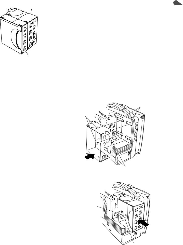
1. INSTALLATION/CONNECTION
Attaching the AA-672P or AA-674P Smart Expansion Unit to the AY series Input Unit |
1 |
|
Input unit |
Attach the smart expansion unit to the input unit before |
|
|
mounting the input unit onto the monitor. Only one smart |
|
|
expansion unit can be attached to the input unit. For details |
|
|
on how to attach the smart expansion unit, refer to the |
|
|
manual provided with the unit. |
|
|
NOTE |
|
|
The AA-672P or AA-674P smart expansion unit does |
|
|
not function when it is attached to the AY-660P input |
|
Smart expansion unit |
unit. |
|
|
|
|
Mounting the AY series Input Unit onto the Monitor
1.Mount the input unit onto the rear of the monitor so that the tabs on the input unit go into the slots on the monitor.
Slots
Tabs
Tabs
2. Slide the input unit in the direction of the arrow until it clicks into place.
Connector on the monitor
Connector on the input unit
Administrator’s Guide BSM-6000 |
1.9 |
1. INSTALLATION/CONNECTION
Using an Optional Handle
A DH-600P handle can be attached to the input unit so that the input unit can be removed from the main unit and carried around easily. For details on the handle, refer to the manual provided with the handle.
 Handle
Attaching the ZS-900P Transmitter
ZS-900P transmitter and DI-590P holder are not available for BSM-6000A series.
The ZS-900P transmitter transmits data from the monitor to a cardiac telemetry system or central monitor. A multiple patient receiver is necessary with the central monitors.
To connect the transmitter to the monitor, the optional DI-590P holder is required. Connect the transmitter to the monitor by referring to the DI-590P holder installation guide.
When the transmitter is connected to the monitor, turn the monitor power on and check that the LED on the transmitter lights in green. Also check that the channel number displayed in the upper part of the screen is correct.
Channel number
CAUTION
When using a ZS-900P transmitter, the measurement values and displayed waveform on the bedside monitor and receiving monitor may differ due to timing delay of the display and other factors. Be careful when reading the value and waveform.
CAUTION
When the ZS-900P transmitter is attached to the bedside monitor, check the alarm, arrhythmia and monitoring settings on the central monitor or telemetry system. The transmitter does not transmit the alarm, arrhythmia and monitoring setting information.
1.10 |
Administrator’s Guide BSM-6000 |
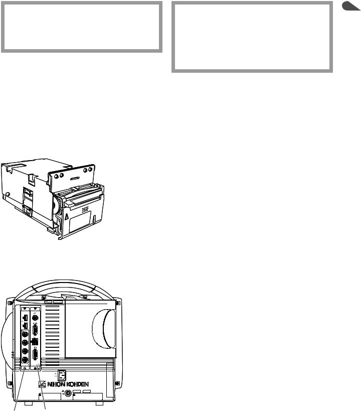
CAUTION
The ZS-900P transmitter can only transmit temperature data from 5 to 45°C (41 to 113°F). Be careful when reading the value.
1. INSTALLATION/CONNECTION
1
CAUTION
The ZS-900P transmitter can only transmit CO2 data from 0 to 100 mmHg (0 to 13.3 kPa). When the transmitting data is out of this range, the receiving monitor displays it as 100 mmHg. Be careful when reading the value.
NOTE
•Before connecting the transmitter, turn off the monitor power.
•The ZS-900P transmitter does not comply with the CE mark.
•A ZB-800P or ZB-900P transmitter cannot be used on this monitor.
Installing the WS-671P Recorder Module
Install the optional WS-671P recorder module in the monitor by referring to the WS-671P recorder module installation guide. To load the recording paper, refer to Operator’s Manual or Section 2 of the User’s Guide Part I.
Installing the QI-631P, QI-632P, QI-634P, QI-671P or QI-672P Interface
QI-672P QI-671P
When the interface is installed in the monitor, external instruments can be connected to the monitor.
The illustration on the left shows both the QI-671P and QI-672P interfaces are installed in the BSM-6701 bedside monitor.
The interface has 2, 3, 4 or 6 sockets.
For BSM-6301:
•QI-631P: RS-232C, RGB
•QI-632P: USB, multi-link, alarm signal output
•QI-634P: USB, multi-link
For BSM-6501 and BSM-6701:
•QI-671P: Multi-link, RS-232C, alarm signal output, RGB
•QI-672P: 2 USB, 4 multi-link
Install the optional interface in the monitor by referring to the manual provided with the interface.
Administrator’s Guide BSM-6000 |
1.11 |

1. INSTALLATION/CONNECTION
Connecting the Mouse
QI-672P interface
Mouse
To connect the mouse, the QI-632P, QI-634P or QI-672P interface is required. The QI-632P and QI-634P interfaces are for BSM-6301. The QI-672P interface  is for BSM-6501 and BSM-6701.

 The illustration on the left shows both the QI-672P and QI-671P interfaces are


 installed in the BSM-6701 bedside monitor.
Connect the mouse cable to the USB socket on the interface which is installed in the monitor.
Connecting the Bar Code Reader
QI-672P interface
Bar code reader
To connect the bar code reader, the QI-632P, QI-634P or QI-672P interface is required. The QI-632P and QI-634P interfaces are for BSM-6301. The QI-672P  interface is for BSM-6501 and BSM-6701.
 The illustration on the left shows both the QI-672P and QI-671P interfaces
 installed in the BSM-6701 bedside monitor.
 Connect the bar code reader cable to the USB socket on the interface which is
 installed in the monitor.


 Refer to the “Setting the Bar Code Reader” later in this section for setting the bar
 code reader.
1.12 |
Administrator’s Guide BSM-6000 |
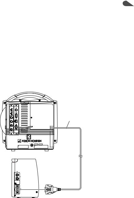
1. INSTALLATION/CONNECTION
Connecting the JA-690PA or JA-694PA Data Acquisition Unit |
1 |
To connect the JA-690PA or JA-694PA data acquisition unit, the YS-096P2 or YS-096P3 unit connection cable is required. Connect the cable to the bedside monitor and to the unit connection socket on the data acquisition unit.
For details on how to use the data acquisition unit, refer to the data acquisition unit operator’s manual.
NOTE
•Connect the unit connection cable to the unit connection socket on the data acquisition unit straight until it locks firmly.
•Keep the cable out of the way by running it along the floor or wall. Otherwise people may trip over it, causing the instrument to fall and injure the patient and operator.
YS-096P2/YS-096P3 unit connection cable
Administrator’s Guide BSM-6000 |
1.13 |
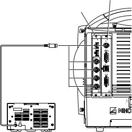
1. INSTALLATION/CONNECTION
Connecting External Instruments
To connect the external instruments, the QI-632P or QI-634P interface for BSM6301 or QI-671P or QI-672P interface for BSM-6501 and BSM-6701 must be installed in the monitor.
Connecting a GF-110PA or GF-210R Multigas Unit, GF-120PA or GF220R Multigas/Flow Unit or AE-918P Neuro Unit
NOTE
GF-210R multigas unit, GF-120PA or GF-220R multigas/flow unit and AE918P neuro unit are not available for the BSM-6000A series.
Connect the GF-110PA or GF-210R multigas unit, GF-120PA or GF-220R multigas/flow unit orAE-918P neuro unit to one of the multi-link sockets on the
QI-632P, QI-634P, QI-671P or QI-672P interface.
NOTE
When a multigas unit or multigas/flow unit is connected to the monitor and the monitor is in operation, do not connect any other instrument to the monitor with a multi-link cable. If another multi-link cable is connected to the main unit during operation, the multigas unit or multigas/flow
unit may enter warmup status and automatically restart monitoring 45 seconds (AG-920R, GF-110PA, GF-120PA) or 6 minutes (GF-210R, GF220R) after warmup.
The following example shows both the QI-671P and QI-672P interfaces installed in the BSM-6701 bedside monitor and a GF-120PAmultigas/flow unit connected.
Connecting Example
QI-671P interface
QI-672P interface
GF-120PA multigas/flow unit
1.14 |
Administrator’s Guide BSM-6000 |
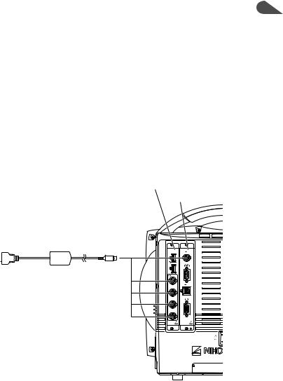
1. INSTALLATION/CONNECTION |
|
Connecting an External Instrument Using a QF Series Interface or IF |
1 |
Series Communication Cable
Connect the QF series interface cable or IF series communication cable to the external instrument and to one of the multi-link sockets on the QI-632P, QI-634P, QI-671P or QI-672P interface.
The following example shows both the QI-671P and QI-672P interfaces installed in the BSM-6701 bedside monitor.
NOTE
Do not connect or remove the QF series interface or IF series communication cable connector while the monitor power is on. The monitor might not function properly.
QI-672P interface
QI-671P interface
To external devices 
QF series interface or
IF series communication cable
Connecting a Sub Display
A sub display can be connected to the bedside monitor. Connect the sub display to the RGB socket on the QI-631P interface for a BSM-6301 bedside monitor or to the QI-671P interface for a BSM-6501 or BSM-6701 bedside monitor. The sub display must meet the following specifications.An NEC LCD191VXM or equivalent display is recommended.
Minimum specifications for BSM-6701 display:
•Resolution: 1024 × 768
•InputAnalog RGB: 0.7 Vp-p
•V-sync: 60.0 Hz
•H-sync: 48.4 kHz
Minimum specifications for BSM-6301 and BSM-6501 display:
•Resolution: 800 × 600
•InputAnalog RGB: 0.7 Vp-p
•V-sync: 60.3 Hz
•H-sync: 37.9 kHz
Administrator’s Guide BSM-6000 |
1.15 |
1. INSTALLATION/CONNECTION
To connect the display to the interface, use the YS-080P3 RGB cable (10 m). The sub display must be connected to the SM-800R isolation transformer.
The screen to be displayed on the sub display can be set to either of the following on the DISPLAY page of the SYSTEM SETUP window. Refer to Section 3.
• SLAVE: Same screen as the bedside monitor.
• HOME SCREEN: The home screen is always displayed.
1.16 |
Administrator’s Guide BSM-6000 |
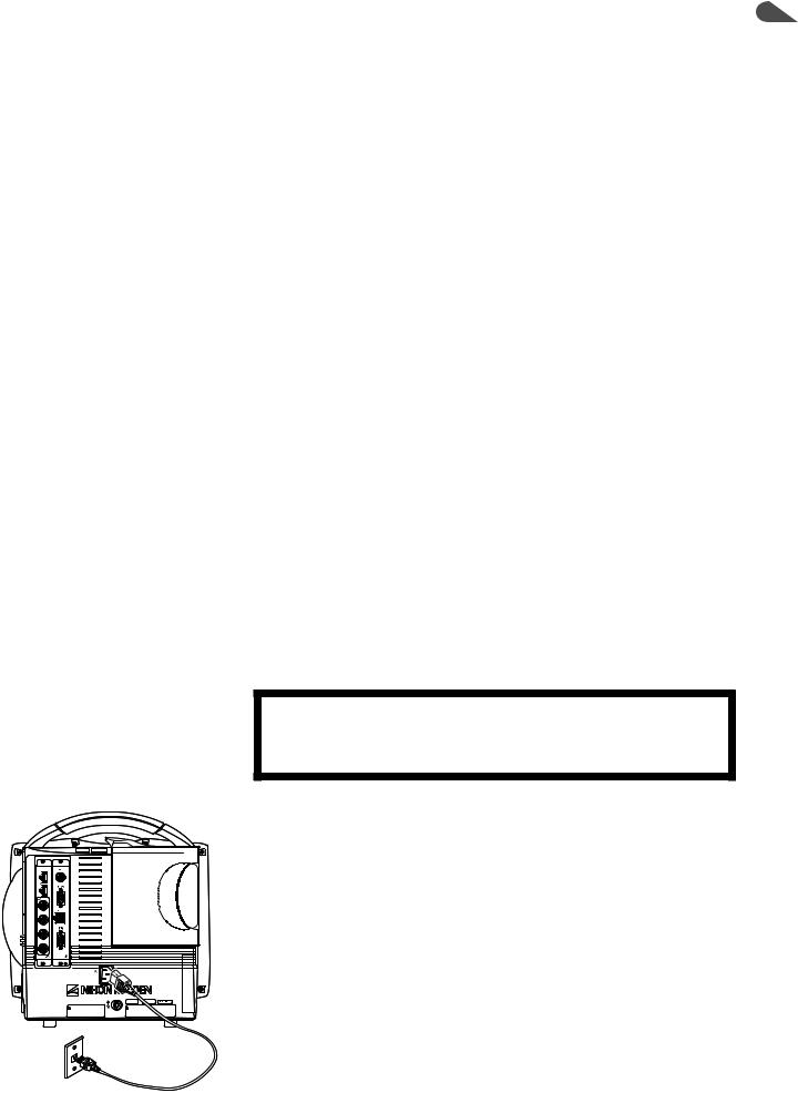
1. INSTALLATION/CONNECTION
Connecting the Power Cord and Grounding Lead |
1 |
|
|
|
|
General |
|
The monitor can operate on either battery or AC power. |
|
When the power cord is plugged into an AC outlet and the power switch on the |
|
front panel is turned on, the monitor operates on AC power. |
|
When a battery pack is inserted and the power cord is disconnected or there is a |
|
sudden power failure, the monitor automatically switches to battery power. |
|
The battery pack is charged when the power cord is plugged into an AC outlet |
|
and the AC current is supplied to the monitor. The battery pack is also charged |
|
during monitoring. |
|
The monitor can operate for about 60 minutes on the BSM-6301 and BSM-6501 or about 45 minutes on the BSM-6701 with a new fully charged battery pack when:
•Used in normal temperature.
•Recorder is stopped.
•No alarm occurs.
•Monitoring ECG, respiration (impedance) and SpO2.
•<POWER SAVING MODE> on the SYSTEM SETUP window is set to ON.
•<SYNC SOUND VOLUME> on the VOLUME window is set to OFF.
•NIBP measurement interval is 15 minutes.
•QI-671P and QI-672P interfaces or QI-631P and QI-632P or QI-634P interfaces are installed in the monitor.
Connecting the Power Cord
WARNING
Only use the provided power cord. Using other power cords may result in electrical shock or injury to the patient and operator.
Connect the provided power cord to the AC SOURCE socket on the rear panel of the monitor and plug the cord into a 3-prong AC outlet.
When AC power is supplied to the monitor, the AC power lamp on the front panel lights.
NOTE
If the AC power lamp does not light, check the power cord connection.
Administrator’s Guide BSM-6000 |
1.17 |
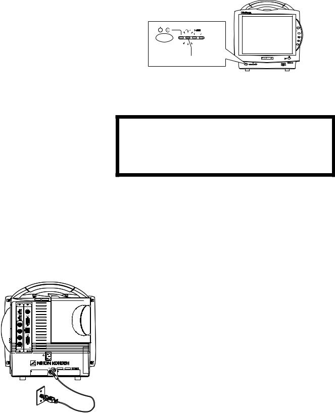
1. INSTALLATION/CONNECTION
AC power lamp lights
Grounding the Monitor
WARNING
When several medical instruments are used together, ground all instruments to the same one-point ground. Any potential difference between instruments may cause electrical shock to the patient and operator.
When more than one electrical instrument is used, there may be electrical potential difference between the instruments. The potential difference between the instruments may cause current to flow to the patient connected to the instruments, resulting in electrical shock (micro shock).
Always perform equipotential grounding when required. It is often required in the operating room, ICU room, CCU room, cardiac catheterization room and X- ray room. Consult with a biomedical engineer to determine if it is required.
When equipotential grounding is required, connect the equipotential ground terminal on the instrument to the equipotential ground terminal on the wall (equipotential grounding system) with the equipotential grounding lead (potential equalization conductor).
1.18 |
Administrator’s Guide BSM-6000 |

Connecting the Monitor to the Network
1. INSTALLATION/CONNECTION
1
The network connection method differs according to the installation location of the monitor and the network components. The network connection must comply with IEC 60601-1-1 “General Requirements for Safety of Medical Electrical Equipment”. For details, refer to the “Network and System Installation Guide” which is available from your Nihon Kohden representative.
WARNING
Connect the monitor to network as specified. Otherwise the patient and operator may receive electrical shock or injury. To connect the network, contact your Nihon Kohden representative.
WARNING
Install all network devices, including printer and hubs, outside the patient environment (IEC
60601-1-1). If they are installed inside the patient environment, the patient or operator may receive electrical shock or injury. For installation, contact your Nihon Kohden representative.
WARNING
In a network where this monitor is connected, connect only the specified instruments. Unspecified instruments may cause electrical shock or injury to the patient and operator or cause instrument malfunction, instrument stop, or data loss.
WARNING
Check the software version number of the monitor before connecting it to the network. Different software versions have different communication methods. More than one communication method in a network may cause communication failure. For details, refer to the Network and System Installation Guide.
Administrator’s Guide BSM-6000 |
1.19 |
 Loading...