


Nihon-Kohden Celltak MEK-6400 Service manual
Automated
Hematology Analyzer
MEK-6400/MEK-6410/MEK-6420
MEK-6400C MEK-6410C MEK-6400J MEK-6410J MEK-6400K MEK-6410K
MEK-6420C MEK-6420J MEK-6420K
If you have any comments or suggestions |
|
on this manual, please contact us at: |
0634-900086B |
www.nihonkohden.com |
|
|
CONTENTS |
|
Contents |
|
|
GENERAL HANDLING PRECAUTIONS .............................................................................. |
i |
|
WARRANTY POLICY ......................................................................................................... |
ii |
|
RESPONSIBILITIES – PROFESSIONAL USERS ............................................................. |
ii |
|
EMC Related Caution ........................................................................................................ |
iii |
|
Conventions Used in this Manual and Instrument ............................................................. |
v |
|
Warnings, Cautions and Notes ................................................................................ |
v |
Section 1 |
General ................................................................................. |
1.1 |
|
Introduction .................................................................................................................... |
1.2 |
|
Service Policy ................................................................................................................ |
1.3 |
|
Specifications ................................................................................................................ |
1.4 |
|
Measured Parameters, Ranges and Reproducibility to Specimen from Venous |
|
|
Blood .......................................................................................................... |
1.4 |
|
Standardization Analysis Method ............................................................... |
1.4 |
|
Detection Method ....................................................................................... |
1.5 |
|
Dilution Ratio .............................................................................................. |
1.5 |
|
Counting Time ............................................................................................ |
1.5 |
|
Display ....................................................................................................... |
1.5 |
|
Data Storage .............................................................................................. |
1.5 |
|
Environmental Conditions ........................................................................... |
1.5 |
|
Power Requirements .................................................................................. |
1.5 |
|
Dimensions and Weight .............................................................................. |
1.6 |
|
Electromagnetic Compatibility .................................................................... |
1.6 |
|
Safety ........................................................................................................ |
1.6 |
|
Panel Description ........................................................................................................... |
1.7 |
|
Front Panel ........................................................................................................... |
1.7 |
|
Right Side Panel ................................................................................................... |
1.8 |
|
Rear Panel ........................................................................................................... |
1.9 |
|
Composition .................................................................................................................. |
1.10 |
|
MEK-6400 ........................................................................................................... |
1.10 |
|
MEK-6410 ........................................................................................................... |
1.11 |
|
MEK-6420 ........................................................................................................... |
1.12 |
|
Interference Substances ............................................................................................... |
1.13 |
Section 2 |
Troubleshooting .................................................................. |
2.1 |
|
Check Procedure Flowchart ........................................................................................... |
2.4 |
|
Operating Condition and Blood Sample Checks ............................................................. |
2.5 |
|
Operating Condition Check ................................................................................... |
2.5 |
|
Blood Sample Handling Check ............................................................................. |
2.5 |
|
Pre-dilution Sample Preparation Check ................................................................ |
2.5 |
|
Checking the Hematology Analyzer ................................................................................ |
2.7 |
|
Checking Background Noise ................................................................................ |
2.7 |
|
Measurement ............................................................................................. |
2.7 |
Service Manual MEK-6400/6410/6420 |
C.1 |
CONTENTS
Parameter Data Check with Diluent |
............................................................ 2.7 |
Reducing Background Noise ...................................................................... |
2.8 |
Background Noise Problems ...................................................................... |
2.9 |
Checking the Reproducibility ................................................................................ |
2.9 |
Checking Procedure ................................................................................... |
2.9 |
CV Values ................................................................................................. |
2.10 |
Checking Accuracy ....................................................................................................... |
2.11 |
Checking Procedure ............................................................................................ |
2.11 |
Poor WBC Reproducibility .................................................................................... |
2.11 |
Poor HGB Reproducibility .................................................................................... |
2.12 |
Poor RBC Reproducibility .................................................................................... |
2.13 |
Poor PLT Reproducibility ..................................................................................... |
2.14 |
Poor HCT or MCV Reproducibility ....................................................................... |
2.15 |
Solving Problems from Alarm Messages ...................................................................... |
2.16 |
A001: No diluent ........................................................................................ |
2.16 |
A005: No detergent ................................................................................... |
2.16 |
A007: No lysing reagent ............................................................................ |
2.17 |
A009: WBC priming error ........................................................................... |
2.17 |
A010: RBC PRIMING ERROR ................................................................... |
2.17 |
A021: WBC level 1 .................................................................................... |
2.17 |
A022: WBC level 2 .................................................................................... |
2.18 |
A023: WBC level 3 .................................................................................... |
2.18 |
A024: WBC bubble 1 ................................................................................. |
2.18 |
A025: WBC bubble 2 ................................................................................. |
2.18 |
A026: WBC bubble 3 ................................................................................. |
2.19 |
A027: WBC bubble 4 ................................................................................. |
2.19 |
A029: WBC clog ........................................................................................ |
2.19 |
A030: WBC sample error ........................................................................... |
2.19 |
A031: WBC noise 2 ................................................................................... |
2.20 |
A032: WBC noise 1 ................................................................................... |
2.20 |
A036: WBC upper manometer dirty ........................................................... |
2.20 |
A037: WBC lower manometer dirty ............................................................ |
2.20 |
A041: RBC level 1 ..................................................................................... |
2.21 |
A042: RBC level 2 ..................................................................................... |
2.21 |
A043: RBC level 3 ..................................................................................... |
2.21 |
A044: RBC bubble 1 .................................................................................. |
2.22 |
A045: RBC bubble 2 .................................................................................. |
2.22 |
A046: RBC bubble 3 .................................................................................. |
2.22 |
A047: RBC bubble 4 .................................................................................. |
2.22 |
A049: RBC clog ......................................................................................... |
2.22 |
A050: RBC sample error ............................................................................ |
2.23 |
A051: RBC noise 2 .................................................................................... |
2.23 |
A052: PLT noise 1 ..................................................................................... |
2.23 |
A053: PLT noise 3 ..................................................................................... |
2.23 |
A057: RBC upper manometer dirty ............................................................ |
2.23 |
A058: RBC lower manometer dirty ............................................................ |
2.23 |
A061: HGB voltage low ............................................................................. |
2.24 |
A062: HGB voltage high ............................................................................ |
2.24 |
A063: HGB circuit error ............................................................................. |
2.24 |
C.2 |
Service Manual MEK-6400/6410/6420 |
|
CONTENTS |
A072: Tube holder open ............................................................................. |
2.24 |
A073: Tube in the holder ............................................................................ |
2.25 |
A091: Room temperature high ................................................................... |
2.25 |
A092: Room temperature low .................................................................... |
2.25 |
A093: Internal temperature high ................................................................ |
2.25 |
A094: Internal temperature low .................................................................. |
2.25 |
A095: Power supply temp high .................................................................. |
2.25 |
! APPEARS ON THE RIGHT OF WBC MEASURED VALUE .................... |
2.26 |
! APPEARS ON THE RIGHT OF MCHC MEASURED VALUE .................. |
2.26 |
C APPEARS ON THE RIGHT OF WBC OR PLT MEASURED VALUE or |
|
PLT Clumps appears ................................................................................. |
2.27 |
OTHER FLAGS ......................................................................................... |
2.27 |
Solving Problems from System Error Messages ........................................................... |
2.28 |
E001: DILUTER INITIALIZE ERROR ........................................................ |
2.28 |
E021: SAMPLER INITIALIZE ERROR ...................................................... |
2.28 |
E041: SUB BATH INITIALIZE ERROR ...................................................... |
2.28 |
E101: BATH DRAIN ERROR ..................................................................... |
2.29 |
E122: CHECK SETTINGS ........................................................................ |
2.29 |
E123: MEMORY ERROR .......................................................................... |
2.29 |
E124: CIRCUIT ERROR ............................................................................ |
2.29 |
E126: TOUCH PANEL ERROR .................................................................. |
2.29 |
E141: CAP PIERCE INITIALIZE ERROR ................................................. |
2.29 |
Service Maintenance Screens ....................................................................................... |
2.30 |
Displaying the SERVICE Screen ......................................................................... |
2.30 |
CHECK MENU Screen ........................................................................................ |
2.32 |
UNIT MAINTE Screen ......................................................................................... |
2.32 |
MD-640V ................................................................................................... |
2.33 |
MS-640V ................................................................................................... |
2.33 |
MS-641V (MEK-6400 only) ........................................................................ |
2.34 |
MV & PUMP CHK ..................................................................................... |
2.34 |
CONT MEASURE Screen ................................................................................... |
2.35 |
SETTING MENU Screen ..................................................................................... |
2.35 |
ADV. SETTINGS Screen ........................................................................... |
2.35 |
REAGENT FACTOR Screen ...................................................................... |
2.36 |
USER MAINTENANCE Screen ................................................................. |
2.36 |
PANIC VALUE Screen (for MEK-6400 and MEK-6410) .............................. |
2.37 |
FLAG SETTINGS Screen ......................................................................... |
2.37 |
BAR CODE PORT Screen ........................................................................ |
2.37 |
UNIT CAL Screen ..................................................................................... |
2.38 |
MONITOR Screen ............................................................................................... |
2.38 |
X10-CV screen .................................................................................................... |
2.39 |
INITIAL MENU Screen ........................................................................................ |
2.40 |
OTHER MENU Screen ........................................................................................ |
2.40 |
PRINT SETTINGS Screen .................................................................................. |
2.40 |
Section 3 Board/Unit Description ....................................................... |
3.1 |
Board and Unit Location ................................................................................................. |
3.3 |
Right Side View .................................................................................................... |
3.3 |
Service Manual MEK-6400/6410/6420 |
C.3 |
CONTENTS |
|
Left Side View ...................................................................................................... |
3.3 |
Front View ............................................................................................................ |
3.4 |
Top View ............................................................................................................... |
3.4 |
MC-640V Measuring Unit ................................................................................................ |
3.5 |
MD-640V Combination Syringe Pump Unit ..................................................................... |
3.5 |
MP-640V Pump Unit ....................................................................................................... |
3.6 |
PV-641V Front Panel Unit ............................................................................................... |
3.6 |
JQ-640V Inlet/Outlet Unit ............................................................................................... |
3.7 |
JQ-641V/JQ-642V Valve Unit ......................................................................................... |
3.7 |
JQ-641V Valve Unit .............................................................................................. |
3.7 |
JQ-642V Valve Unit .............................................................................................. |
3.7 |
MS-640V Sampler Unit ................................................................................................... |
3.8 |
MS-641V Cap Pierce Unit (MEK-6400 only) ................................................................... |
3.8 |
MR-640V Rinse Unit (MEK-6410/6420 only) ................................................................... |
3.9 |
UT-7192 AMP CONTROL Board ..................................................................................... |
3.9 |
UT-7193 POWER Board ................................................................................................ |
3.10 |
UT-7198 MEASURING Board ........................................................................................ |
3.10 |
UT-7201 HGB AMP Board and UT-7202 HGB LED Board .............................................. |
3.11 |
UT-7200 MIXED PUMP Board ....................................................................................... |
3.11 |
UT-7205 PRINTER DRIVER Board ................................................................................ |
3.12 |
UT-7203 KEY Board ...................................................................................................... |
3.12 |
UT-7199 LIQUID SENSOR Board .................................................................................. |
3.13 |
XP-602V/XP-612V 2-way Electromagentic Valve .......................................................... |
3.13 |
Section 4 |
Disassembly and Assembly .............................................. |
4.1 |
|
Before You Begin ............................................................................................................ |
4.2 |
|
Warnings and Cautions ......................................................................................... |
4.2 |
|
Required Tools ...................................................................................................... |
4.2 |
|
Caution and Notes Related to Valve Joint, Black Screw and Tube Joint in the |
|
|
Instrument ............................................................................................................ |
4.3 |
|
Board and Unit Location ....................................................................................... |
4.3 |
|
Turning the Power Off ..................................................................................................... |
4.4 |
|
Cleaning and Draining the Fluid Pathway .............................................................. |
4.4 |
|
Turning the Power Off ........................................................................................... |
4.5 |
|
Removing the Right Side Cover, Top Cover and Rear Cover ........................................... |
4.6 |
|
Reattaching the Right Side Cover, Top Cover and Rear Cover ............................. |
4.7 |
|
Removing the Front Panel Unit ....................................................................................... |
4.8 |
|
Reattaching the Front Panel Unit .......................................................................... |
4.9 |
|
Installing the WA-640VK Printer Unit (Option) ................................................................ |
4.10 |
|
Removing the Measuring Unit ....................................................................................... |
4.12 |
|
Reattaching the Measuring Unit .......................................................................... |
4.13 |
|
Accessing the Connectors on the POWER Board ......................................................... |
4.14 |
|
Reassembling the Board ..................................................................................... |
4.14 |
|
Removing the Combination Syringe Pump Unit ............................................................. |
4.15 |
|
Reattaching the Combination Syringe Pump Unit ................................................ |
4.16 |
|
Removing the Pump Unit ............................................................................................... |
4.17 |
|
Reattaching the Pump Unit ................................................................................. |
4.18 |
|
Removing the Sampler Unit ........................................................................................... |
4.19 |
C.4 |
Service Manual MEK-6400/6410/6420 |
|
|
CONTENTS |
|
Reattaching the Sampler Unit.............................................................................. |
4.22 |
|
Removing the Cap Pierce Unit or Rinse Unit ................................................................. |
4.23 |
|
Reattaching the Cap Pierce Unit or Rinse Unit .................................................... |
4.24 |
|
Removing the Inlet/Outlet Unit ...................................................................................... |
4.25 |
|
Reattaching the Inlet/Outlet Unit ......................................................................... |
4.26 |
|
Removing the Valve Unit ............................................................................................... |
4.26 |
|
Reattaching the Valve Unit .................................................................................. |
4.27 |
|
Removing the AMP CONTROL Board ........................................................................... |
4.28 |
|
Reattaching the AMP CONTROL Board .............................................................. |
4.29 |
|
Removing the POWER Board ........................................................................................ |
4.30 |
|
Reattaching the POWER Board .......................................................................... |
4.31 |
|
Removing the MEASURING Board ............................................................................... |
4.32 |
|
Reattaching the MEASURING Board .................................................................. |
4.33 |
|
Removing the MIXED PUMP Board .............................................................................. |
4.34 |
|
Reattaching the MIXED PUMP Board ................................................................. |
4.34 |
|
Removing the PRINTER DRIVER Board ....................................................................... |
4.35 |
|
Reattaching the PRINTER DRIVER Board .......................................................... |
4.35 |
|
Removing the KEY Board .............................................................................................. |
4.36 |
|
Reattaching the KEY Board ................................................................................ |
4.36 |
|
Removing the LIQUID SENSOR Board ......................................................................... |
4.37 |
|
Reattaching the LIQUID SENSOR Board ............................................................ |
4.37 |
|
Removing the LCD ........................................................................................................ |
4.38 |
|
Reattaching the LCD ........................................................................................... |
4.39 |
|
Removing the Transformer ............................................................................................. |
4.40 |
|
Reattaching the Transformer ................................................................................ |
4.40 |
Section 5 |
Adjustment........................................................................... |
5.1 |
|
General ........................................................................................................................... |
5.2 |
|
Adjusting the HGB Sensor Output Voltage ..................................................................... |
5.3 |
|
Adjusting the Upper and Lower Sensor Output Voltages of the Manometers .................. |
5.6 |
|
Adjusting the Liquid Sensor Output Voltages .................................................................. |
5.9 |
Section 6 |
Maintenance ........................................................................ |
6.1 |
|
General ........................................................................................................................... |
6.3 |
|
Disposing of Waste ............................................................................................... |
6.4 |
|
Repair Parts Availability Policy ............................................................................. |
6.4 |
|
Parts to be Replaced Periodically ......................................................................... |
6.4 |
|
Maintenance Schedule ................................................................................................... |
6.5 |
|
Displaying Operation History Screen .............................................................................. |
6.6 |
|
Maintenance Check Sheet ............................................................................................. |
6.8 |
|
Before Maintenance Procedure ..................................................................................... |
6.12 |
|
Strong Cleaning ................................................................................................... |
6.12 |
|
Draining Measurement Baths and Sub Baths ...................................................... |
6.13 |
|
Turning Power Off ................................................................................................ |
6.14 |
|
Daily Maintenance Procedures ...................................................................................... |
6.15 |
|
Checking Reagents and Other Consumables ...................................................... |
6.15 |
|
Checking the Appearance of the Analyzer .......................................................... |
6.15 |
Service Manual MEK-6400/6410/6420 |
C.5 |
CONTENTS
Disinfecting the Surface of the Analyzer ................................................... |
6.16 |
Cleaning the Surface of the Analyzer ........................................................ |
6.16 |
Checking the Reagents Connection Tubes .......................................................... |
6.16 |
Checking the Power Cord and Grounding Lead .................................................... |
6.16 |
Checking the External Instrument Connection .................................................... |
6.16 |
Checking the Power On ....................................................................................... |
6.17 |
Calibrating the Touch Screen ..................................................................... |
6.17 |
Checking the Date and Time ............................................................................... |
6.17 |
Clock Accuracy ......................................................................................... |
6.18 |
Measuring Background Noise .............................................................................. |
6.18 |
Measuring Hematology Control ........................................................................... |
6.20 |
Checking Measurement Baths and Sub Baths .................................................... |
6.21 |
Checking Pump Tube ........................................................................................... |
6.21 |
Weekly/Every 300 Counts Maintenance Procedures ..................................................... |
6.21 |
Checking/Cleaning Filters ................................................................................... |
6.21 |
Monthly/Every 1,000 Counts Maintenance Procedures ................................................. |
6.22 |
Replacing Filters ................................................................................................. |
6.22 |
Materials Required .................................................................................... |
6.22 |
Procedure ................................................................................................. |
6.22 |
Checking and Cleaning Measurement Baths and Sub Baths ............................... |
6.23 |
Materials Required .................................................................................... |
6.23 |
Procedure ................................................................................................. |
6.24 |
Checking and Cleaning/Replacing the Rinse Unit and Cap Pierce Nozzle ........... |
6.26 |
Materials Required .................................................................................... |
6.26 |
Procedure ................................................................................................. |
6.27 |
Every Four Months/Every 3,000 Counts Maintenance Procedures ............................... |
6.29 |
Checking and Cleaning/Replacing the Sampling Nozzles .................................... |
6.29 |
Materials Required .................................................................................... |
6.29 |
Procedure ................................................................................................. |
6.29 |
Replacing Pump Tube .......................................................................................... |
6.32 |
Materials Required .................................................................................... |
6.32 |
Procedure ................................................................................................. |
6.32 |
Every Six Months/As-Required Maintenance Procedures ............................................. |
6.35 |
Removing a Clog from the Aperture .................................................................... |
6.35 |
Cleaning Aperture Caps ...................................................................................... |
6.36 |
Materials Required .................................................................................... |
6.36 |
Procedures................................................................................................ |
6.36 |
Cleaning the External Electrodes on the Measurement Baths ............................ |
6.39 |
Checking the Sensor Monitor Screen .................................................................. |
6.40 |
Checking the Circuit ............................................................................................ |
6.41 |
_ |
|
Checking the X-R Values ..................................................................................... |
6.43 |
Checking the Current Calibration Coefficients ..................................................... |
6.43 |
Checking the New Calibration Coefficients .......................................................... |
6.43 |
Checking the Prime Function .............................................................................. |
6.44 |
Checking the Drain Function ............................................................................... |
6.44 |
Checking the Cleaning Function .......................................................................... |
6.44 |
Checking the Dispensing Function ...................................................................... |
6.45 |
Checking the External Instruments Function ...................................................... |
6.45 |
Printers ..................................................................................................... |
6.45 |
C.6 |
Service Manual MEK-6400/6410/6420 |
|
CONTENTS |
Hand-held Bar Code Reader ...................................................................... |
6.45 |
PC ............................................................................................................. |
6.45 |
Checking the Power Cord .................................................................................... |
6.45 |
Checking the Resistance of the Protective Ground Line ..................................... |
6.45 |
Checking the Earth Leakage Current ................................................................... |
6.46 |
Section 7 Test Point, Variable Resistor, LED and Switch on Board 7.1
|
AMP CONTROL Board ................................................................................................... |
7.2 |
|
POWER Board ............................................................................................................... |
7.4 |
|
MEASURING Board ....................................................................................................... |
7.5 |
|
HGB AMP Board ............................................................................................................ |
7.6 |
|
LIQUID SENSOR Board ................................................................................................. |
7.6 |
|
MIXED PUMP Board ...................................................................................................... |
7.7 |
|
KEY Board ..................................................................................................................... |
7.7 |
|
PRINTER DRIVER Board ............................................................................................... |
7.8 |
Section 8 |
Socket Pin Assignment...................................................... |
8.1 |
|
ZK-820V Bar Code Reader Socket ....................................................................... |
8.2 |
|
Serial Port 1/Serial Port 2 .................................................................................... |
8.2 |
|
Printer Socket ...................................................................................................... |
8.2 |
|
USB Socket ......................................................................................................... |
8.2 |
Section 9 |
Installation............................................................................ |
9.1 |
|
Connecting the Power Cord and Grounding the Analyzer ................................................ |
9.2 |
|
Connecting the Power Cord .................................................................................. |
9.2 |
|
Equipotential Grounding ....................................................................................... |
9.2 |
|
Connecting Tubes and Installing Reagents ..................................................................... |
9.3 |
|
Materials Required ............................................................................................... |
9.3 |
|
Connecting Tubes ................................................................................................. |
9.4 |
|
Diluent Tube ............................................................................................... |
9.4 |
|
Detergent Tube ........................................................................................... |
9.5 |
|
Lysing Reagent Tube .................................................................................. |
9.6 |
|
Waste Fluid Tube ........................................................................................ |
9.6 |
|
Turning Power On/Off ..................................................................................................... |
9.7 |
|
Turning On the Power ........................................................................................... |
9.7 |
|
Cleaning the Fluid Path After Turning the Power On (PRIME ON INSTALL) .......... |
9.8 |
|
Turning Off the Power ........................................................................................... |
9.9 |
|
Checking Accuracy ....................................................................................................... |
9.10 |
|
Checking the Circuit ............................................................................................ |
9.10 |
|
Measuring Background Noise.............................................................................. |
9.10 |
|
Calibrating ........................................................................................................... |
9.11 |
Service Manual MEK-6400/6410/6420 |
C.7 |
GENERAL HANDLING PRECAUTIONS
This device is intended for use only by qualified medical personnel.
Use only Nihon Kohden approved products with this device. Use of non-approved products or in a non-approved manner may affect the performance specifications of the device. This includes, but is not limited to, batteries, recording paper, pens, extension cables, electrode leads, input boxes and AC power.
Please read these precautions thoroughly before attempting to operate the instrument.
1.To safely and effectively use the instrument, its operation must be fully understood.
2.When installing or storing the instrument, take the following precautions:
(1)Avoid moisture or contact with water, extreme atmospheric pressure, excessive humidity and temperatures, poorly ventilated areas, and dust, saline or sulphuric air.
(2)Place the instrument on an even, level floor. Avoid vibration and mechanical shock, even during transport.
(3)Avoid placing in an area where chemicals are stored or where there is danger of gas leakage.
(4)The power line source to be applied to the instrument must correspond in frequency and voltage to product specifications, and have sufficient current capacity.
(5)Choose a room where a proper grounding facility is available.
3.Before Operation
(1)Check that the instrument is in perfect operating order.
(2)Check that the instrument is grounded properly.
(3)Check that all cords are connected properly.
(4)Pay extra attention when the instrument is in combination with other instruments to avoid misdiagnosis or other problems.
(5)All circuitry used for direct patient connection must be doubly checked.
(6)Check that battery level is acceptable and battery condition is good when using battery-operated models.
4.During Operation
(1)Both the instrument and the patient must receive continual, careful attention.
(2)Turn power off or remove electrodes and/or transducers when necessary to assure the patient’s safety.
(3)Avoid direct contact between the instrument housing and the patient.
5.To Shutdown After Use
(1)Turn power off with all controls returned to their original positions.
(2)Remove the cords gently; do not use force to remove them.
(3)Clean the instrument together with all accessories for their next use.
6.The instrument must receive expert, professional attention for maintenance and repairs. When the instrument is not functioning properly, it should be clearly marked to avoid operation while it is out of order.
7.The instrument must not be altered or modified in any way.
8.Maintenance and Inspection
(1)The instrument and parts must undergo regular maintenance inspection at least every 6 months.
(2)If stored for extended periods without being used, make sure prior to operation that the instrument is in perfect operating condition.
Service Manual MEK-6400/6410/6420 |
i |
9.When the instrument is used with an electrosurgical instrument, pay careful attention to the application and/or location of electrodes and/or transducers to avoid possible burn to the patient.
10.When the instrument is used with a defibrillator, make sure that the instrument is protected against defibrillator discharge. If not, remove patient cables and/or transducers from the instrument to avoid possible damage.
WARRANTY POLICY
Nihon Kohden Corporation (NKC) shall warrant its products against all defects in materials and workmanship for one year from the date of delivery. However, consumable materials such as recording paper, ink, stylus and battery are excluded from the warranty.
NKC or its authorized agents will repair or replace any products which prove to be defective during the warranty period, provided these products are used as prescribed by the operating instructions given in the operator’s and service manuals.
No other party is authorized to make any warranty or assume liability for NKC’s products. NKC will not recognize any other warranty, either implied or in writing. In addition, service, technical modification or any other product change performed by someone other than NKC or its authorized agents without prior consent of NKC may be cause for voiding this warranty.
Defective products or parts must be returned to NKC or its authorized agents, along with an explanation of the failure. Shipping costs must be pre-paid.
This warranty does not apply to products that have been modified, disassembled, reinstalled or repaired without Nihon Kohden approval or which have been subjected to neglect or accident, damage due to accident, fire, lightning, vandalism, water or other casualty, improper installation or application, or on which the original identification marks have been removed.
In the USA and Canada other warranty policies may apply.
RESPONSIBILITIES – PROFESSIONAL USERS
This instrument must be used by a professional user with a full knowledge of operating this instrument, only for his/her intended use and according to the instructions for use. Instructions in the operator’s manual must be followed, especially the following points.
•Storage and stability of reagents
•Handling of reagents
•Instrument installation
•Connection of all tubes to inlets and outlets
•Connection of all tubes to reagents and waste container
•Checking the amount of reagents and waste fluid
•Calibration
•Quality control
•Maintaining and servicing
If deviating from the instructions, the professional user does it at the risk and liability of the laboratory and only after validation by the laboratory. Nihon Kohden has no responsibility over such deviations.
ii |
Service Manual MEK-6400/6410/6420 |
EMC RELATED CAUTION
This equipment and/or system complies with the International Standard EN61326-1 for electromagnetic compatibility for electrical equipment and/or system for measurement, control and laboratory use. However, an electromagnetic environment that exceeds the limits or levels stipulated in the EN61326-1, can cause harmful interference to the equipment and/or system or cause the equipment and/or system to fail to perform its intended function or degrade its intended performance. Therefore, during the operation of the equipment and/or system, if there is any undesired deviation from its intended operational performance, you must avoid, identify and resolve the adverse electromagnetic effect before continuing to use the equipment and/or system.
The following describes some common interference sources and remedial actions:
1.Strong electromagnetic interference from a nearby emitter source such as an authorized radio station or cellular phone:
Install the equipment and/or system at another location if it is interfered with by an emitter source such as an authorized radio station. Keep the emitter source such as cellular phone away from the equipment and/or system.
2.Radio-frequency interference from other equipment through the AC power supply of the equipment and/or system:
Identify the cause of this interference and if possible remove this interference source. If this is not possible, use a different power supply.
3.Effect of direct or indirect electrostatic discharge:
Make sure all users and patients in contact with the equipment and/or system are free from direct or indirect electrostatic energy before using it. A humid room can help lessen this problem.
4.Electromagnetic interference with any radio wave receiver such as radio or television:
If the equipment and/or system interferes with any radio wave receiver, locate the equipment and/or system as far as possible from the radio wave receiver.
If the above suggested remedial actions do not solve the problem, consult your Nihon Kohden Corporation subsidiary or distributor for additional suggestions.
This equipment complies with International Standard EN55011 (1999) Group 1, Class B. Class B EQUIPMENT is equipment suitable for use in domestic establishments and in establishments directly connected to a low voltage power supply network which supplies buildings used for domestic purposes.
The CE mark is a protected conformity mark of the European Community. The products herewith comply with the requirements of the IVD Directive 98/79/EEC.
Service Manual MEK-6400/6410/6420 |
iii |

NOTE about Waste Electrical and Electronic Equipment (WEEE) directive 2002/96/EEC For the member states of the European Union only:
The purpose of WEEE directive 2002/96/EEC is, as a first priority, the prevention of waste electrical and electronic equipment (WEEE), and in addition, the reuse, recycling and other forms of recovery of such wastes so as to reduce the disposal of waste.
Contact your Nihon Kohden representative for disposal at the end of its working life.
iv |
Service Manual MEK-6400/6410/6420 |

Conventions Used in this Manual and Instrument
Warnings, Cautions and Notes
Warnings, cautions and notes are used in this manual to alert or signal the reader to specific information.
WARNING
A warning alerts the user to the possible injury or death associated with the use or misuse of the instrument.
CAUTION
A caution alerts the user to possible injury or problems with the instrument associated with its use or misuse such as instrument malfunction, instrument failure, damage to the instrument, or damage to other property.
NOTE
A note provides specific information, in the form of recommendations, prerequirements, alternative methods or supplemental information.
Service Manual MEK-6400/6410/6420 |
v |
This page is intentionally left blank.
vi |
Service Manual MEK-6400/6410/6420 |

Section 1 General 1
Introduction ........................................................................................................................................................ |
1.2 |
Service Policy .................................................................................................................................................... |
1.3 |
Specifications .................................................................................................................................................... |
1.4 |
Measured Parameters, Ranges and Reproducibility to Specimen from Venous Blood..................... |
1.4 |
Standardization Analysis Method ................................................................................................... |
1.4 |
Detection Method ........................................................................................................................... |
1.5 |
Dilution Ratio ................................................................................................................................. |
1.5 |
Counting Time ................................................................................................................................ |
1.5 |
Display .......................................................................................................................................... |
1.5 |
Data Storage .................................................................................................................................. |
1.5 |
Environmental Conditions .............................................................................................................. |
1.5 |
Power Requirements ...................................................................................................................... |
1.5 |
Dimensions and Weight ................................................................................................................. |
1.6 |
Electromagnetic Compatibility ........................................................................................................ |
1.6 |
Safety ............................................................................................................................................ |
1.6 |
Panel Description ............................................................................................................................................... |
1.7 |
Front Panel ............................................................................................................................................... |
1.7 |
Right Side Panel ...................................................................................................................................... |
1.8 |
Rear Panel ............................................................................................................................................... |
1.9 |
Composition ...................................................................................................................................................... |
1.10 |
MEK-6400 ............................................................................................................................................... |
1.10 |
MEK-6410 ............................................................................................................................................... |
1.11 |
MEK-6420 ............................................................................................................................................... |
1.12 |
Interference Substances ................................................................................................................................... |
1.13 |
Service Manual MEK-6400/6410/6420 |
1.1 |

1. GENERAL
Introduction
CAUTION
To maintain the instrument in normal condition, the user must
perform the periodic maintenance. Refer to “Maintenance” of the
operator’s manual.
This service manual provides useful information to qualified service personnel to understand, troubleshoot, service, maintain and repair the MEK-6400/6410/ 6420 Automated Hematology Analyzer (referred to as “the instrument” in this service manual).
The maintenance must be periodically performed because the instrument has fluid paths and precision parts. Accordingly, the user is responsible for performing the periodic maintenance. The “Maintenance” section in this service manual describes the maintenance that should be performed by qualified service personnel. The “Maintenance” section in the operator’s manual describes the maintenance that can be performed by the user.
NOTE
If the instrument has a problem and there has been no periodic maintenance, the instrument will usually be normal again by cleaning the fluid paths or replacing a consumable with a new one.
The information in the operator’s manual is primarily for the user. However, it is important for service personnel to thoroughly read the operator’s manual and service manual before starting to troubleshoot, service, maintain or repair this instrument. This is because service personnel needs to understand the operation of the instrument in order to effectively use the information in the service manual.
For simplicity, the suffix C/J/K will be omitted in this manual. There is no difference in operation and servicing among models with different suffixes unless otherwise specified.
1.2 |
Service Manual MEK-6400/6410/6420 |

1. GENERAL
Service Policy
1
CAUTION
•Be careful not to directly touch any place where blood is or may spread to.
•Wear rubber gloves to protect yourself from infection before doing maintenance.
Nihon Kohden Corporation’s basic policy for technical service is to replace faulty units, printed circuit boards or parts. We do not support componentlevel repair of boards and units outside the factory.
NOTE
•When ordering parts or accessories from your nearest Nihon Kohden Corporation’s representative, please quote the NK code number and part name which is listed in this service manual, and the name or model of the unit in which the required part is located. This will help us to promptly attend to your needs.
•Always use parts and accessories recommended or supplied by Nihon Kohden Corporation to assure maximum performance from your instrument.
Service Manual MEK-6400/6410/6420 |
1.3 |
1. GENERAL
Specifications
Measured Parameters, Ranges and Reproducibility to Specimen from Venous Blood
Specifications except WBC population were determined using hematology control blood (MEK-3DN), counted 10 times
consecutively.
|
|
Reproducibility to Specimen from |
||
Measured Parameters |
Measuring Range |
Venous Blood |
|
|
|
|
(CV: Coefficient of Variation) |
||
WBC: White blood cell count |
MEK-6400/6410: 0 to 59 × 103/µL* |
within 2.0%CV (4.0 to 9.0 × 10 |
3 |
/µL) |
MEK-6420: 0 to 99 × 103/µL |
|
|||
LY%: Lymphocyte percent |
0 to 99.9% |
within 5.0%CV (WBC: 4.0 to 9.0 × 10³/µL, |
||
LY%: 20 to 45%) |
|
|
||
|
|
|
|
|
MO%: Monocyte percent |
0 to 99.9% |
within 12.0%CV (WBC: 4.0 to 9.0 × |
||
103/µL, MO%: 2 to 10%) |
|
|
||
GR%: Granulocyte percent |
0 to 99.9% |
within 5.0%CV (WBC: 4.0 to 9.0 × 10³/µL, |
||
GR%: 40 to 70%) |
|
|
||
|
|
|
|
|
LY: Lymphocyte count |
MEK-6400/6410: 0 to 59 × 103/µL* |
|
|
|
MEK-6420: 0 to 99 × 103/µL |
|
|
|
|
MO: Monocyte count |
MEK-6400/6410: 0 to 59 × 103/µL* |
|
|
|
MEK-6420: 0 to 99 × 103/µL |
|
|
|
|
GR: Granulocyte count |
MEK-6400/6410: 0 to 59 × 103/µL* |
|
|
|
MEK-6420: 0 to 99 × 103/µL |
|
|
|
|
RBC: Red blood cell count |
0 to 14.9 × 10⁶/µL |
within 1.5%CV (5.0 × 10⁶/µL) |
|
|
HGB: Hemoglobin concentration |
0 to 29.9 g/dL |
within 1.5%CV (16 g/dL) |
|
|
HCT: Hematocrit |
0 to 99.9% |
|
|
|
MCV: Mean cell volume |
20 to 199 fL |
within 1.0%CV (70 to 120 fL) |
|
|
MCH: Mean cell hemoglobin |
10 to 50 pg |
|
|
|
MCHC: Mean cell hemoglobin |
10 to 50 g/dL |
|
|
|
concentration |
|
|
|
|
|
|
|
|
|
RDW: Red blood cell distribution |
0 to 50% |
|
|
|
width |
|
|
|
|
|
|
|
|
|
PLT: Platelet count |
0 to 1490 × 103/µL |
within 4.0%CV (3.0 × 10³/µL) |
|
|
PCT: Platelet crit |
0 to 2.9% |
|
|
|
MPV: Mean platelet volume |
0 to 20.0 fL |
|
|
|
PDW: Platelet distribution width |
0 to 50% |
|
|
|
* In panic value recount: 0 to 599 × 103/µL (MEK-6400, MEK-6410 only)
Standardization Analysis Method
WBC: ICSH1988 |
ICSH: The assignment of values to fresh blood used for calibrating automated blood |
|
cell counters. Clin Lab Haematol, 10:203-212, 1988 |
RBC: ICSH1988 |
ICSH: The assignment of values to fresh blood used for calibrating automated blood |
|
cell counters. Clin Lab Haematol, 10:203-212, 1988 |
HGB: NCCLS H15-A2 |
H15-A2: Reference and Selected Procedures for the Quantitative Determination of |
|
Hemoglobin in Blood Second Edition; Approved Standard (1994) |
HCT: NCCLS H7-A2 |
H7-A2: Procedure for Determining Packed Cell Volume by the Microhematocrit |
|
Method Second Edition; Approved Standard (1993) |
PLT: Brecher & Cronkite Method: Morphology and enumeration of human blood platelets, J Appl Physiol 3 365 (Dec) 1950; Brecher G, Cronkite EP
1.4 |
Service Manual MEK-6400/6410/6420 |

|
1. GENERAL |
Detection Method |
1 |
Blood cell count: |
Electrical resistance detection |
Hemoglobin: |
Surfactant method (colorimetric method) |
Hematocrit: |
Histogram calculation |
WBC population: |
Histogram calculation |
Platelet crit: |
Histogram calculation |
RBC distribution width: |
Histogram calculation |
Platelet distribution width: Histogram calculation
Dilution Ratio
•Venous blood
Sample volume: 30 µL in normal dilution mode, about 50 µL in low dilution mode, 10 µL in high dilution mode,
|
|
5 µL in higher dilution mode (low and higher dilution modes are not available on the MEK-6420 |
|
|
|
analyzer) |
|
WBC/HGB: |
|
200:1 (in normal dilution mode) |
|
RBC/PLT: |
|
40,000:1 (in normal dilution mode) |
|
• Pre-dilution blood |
|
|
|
Sample volume: |
10 µL |
20 µL |
|
WBC/HGB: |
|
1200:1 |
600:1 |
RBC/PLT: |
|
240,000:1 |
120,000:1 |
Counting Time |
|
|
|
Closed mode: |
about 90 s/sample (from measurement start to data display, MEK-6400 only) |
||
Open mode: |
about 60 s/sample (from measurement start to data display) |
||
Display |
|
|
|
Display: |
|
5.7 inch, color LCD with backlight and touch screen keys |
|
Resolution: |
|
240 × 320 dots |
|
Screen size: |
|
approx. 86 × 115 mm |
|
Display contents: |
Numerical data, histograms, measuring conditions, alarm message and other messages, touch screen |
||
|
|
keys |
|
Data Storage
Numerical data for all counted parameters for up to 400 samples and histograms for up to 50 samples
Environmental Conditions |
|
|
Storage temperature: |
–20 to 60°C |
|
Operating temperature: |
15 to 30°C |
|
Storage humidity: |
10 to 95% |
|
Operating humidity: |
30 to 85% (Non-condensing) |
|
Storage atmospheric pressure: |
70 to 106 kPa |
|
Operating atmospheric pressure: 70 to 106 kPa |
|
|
Operating altitude: |
less than 3000 m |
|
Power Requirements |
|
|
Power requirements: MEK-6400J, 6410J, 6420J: |
110 to 127 V ±10% AC, 50/60 Hz |
|
MEK-6400C/K, 6410C/K, 6420C/K: 220 to 240 V ±10% AC, 50/60 Hz
Power consumption:less than120 VA
Service Manual MEK-6400/6410/6420 |
1.5 |
1. GENERAL
Dimensions and Weight
Dimensions: 230 W × 450 D × 383 H (mm)
Net weight: approx. 18 kg
Electromagnetic Compatibility
IEC 61326-1 Edition 1.0: 2002 (Annex A)
EN 61326: 1997/ Amendment 3: 2003
CISPR11 Edition 4.1: 2004, Group 1, Class B
EN 55011: 1998 Amendment 1: 1999, Group 1, Class B
The power supply short interruption test is performed through the transformer which has at least three times the power capacity as the instrument.
Safety
Safety standards: IEC 61010-1 Edition 2.0: 2001
EN 61010-1: 2001
IEC 61010-2-101: 2002
EN 61010-2-101: 2002
IEC 61010-2-081: 2002
EN 61010-2-081: 2002
According to the type of protection against electrical shock: |
CLASS I EQUIPMENT |
According to the degree of protection against harmful ingress of water: |
IPX0 (Ordinary EQUIPMENT) |
According to the degree of safety of application in the presence of a FLAMMABLE ANAESTHETIC MIXTURE WITH
AIR, OR WITH OXYGEN OR NITROUS OXIDE: |
EQUIPMENT not suitable for use in the presence of FLAMMABLE |
|
ANAESTHETIC MIXTURE WITH AIR, OR WITH OXYGEN OR |
|
NITROUSOXIDE |
According to the mode of operation: |
CONTINUOUS OPERATION |
EQUIPMENT types (classification): |
Indoor stationary EQUIPMENT |
Pollution Degree: |
2 EQUIPMENT |
Requirements for marking of IN VITRO DIAGNOSTIC instruments: EN1658: 1996
1.6 |
Service Manual MEK-6400/6410/6420 |

1. GENERAL
Panel Description |
1 |
|
|
|
|
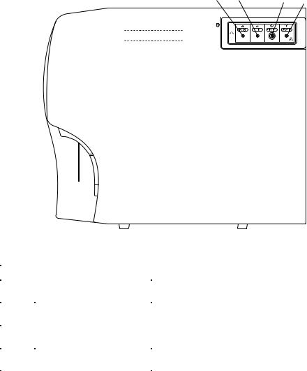
Front Panel |
|
|
8 |
|
8 |
7 |
9 |
7 |
9 |
1 |
10 |
1 |
10 |
|
|
||
2 |
11 |
2 |
11 |
|
|
||
3 |
|
3 |
|
4 |
|
4 |
|
5 |
|
5 |
|
6 |
12 |
6 |
|
15 |
13 |
15 |
13 |
|
|||
|
|
||
16 |
14 |
16 |
14 |
|
|
|
MEK-6400 |
MEK-6410/6420 |
||
|
|
|
|
|
No. |
Name |
Description |
|
|
|
|
|
||
1 |
Main power lamp |
Lights when the [Main power] switch on the rear panel is tuned on. |
||
2 |
Power lamp |
Lights when the [Main power] switch on the rear panel and [Power] key on the front panel |
||
are turned on. |
|
|||
|
|
|
||
|
|
Turns the analyzer power on or off when the [Main power] switch on the rear panel is turned |
||
3 |
Power key |
on. When the power is turned on, priming and self-check are automatically performed, and |
||
|
|
the READY screen appears. |
|
|
4 |
Auto print key |
Switches the printing mode between automatic and manual for the printer. |
||
5 |
Feed key |
Feeds paper of the printer while held down. |
|
|
6 |
Print key |
Prints displayed data on the printer. |
|
|
7 |
Auto print mode |
Lights when automatic printing mode is selected. |
|
|
lamp |
|
|||
|
|
|
||
8 |
LCD display |
Displays various messages, measured data and touch screen keys. |
||
9 |
Reset key |
Stops operation when pressed during operation. Returns to the READY screen when pressed |
||
while changing settings. Use this key only when an error occurs. |
||||
|
|
|||
|
|
Cleans the fluid path, aperture and manometer with detergent. Automatically primes after |
||
10 |
Clean key |
cleaning the fluid path. Press this key when clogging occurs, the manometer becomes dirty |
||
|
|
or bubbles occur in the manometer. |
|
|
|
Eject key |
For closed mode only. Opens the tube holder to set the sample tube. (MEK-6400) |
||
|
Count key |
Aspirates the sample and starts counting when <[Eject] key operation> is set to “Count” on |
||
11 |
the OPERATION screen of the SETTINGS screen. (MEK-6410, MEK-6420) |
|||
|
||||
|
Dispense key |
Dispenses the diluent in pre-dilution blood mode when <[Eject] key operation > is set to |
||
|
“Dispense” on the OPERATION screen of the SETTINGS screen. (MEK-6410, MEK-6420) |
|||
|
|
|||
12 |
Tube holder |
For closed mode only. Holds a sealed vacuum blood collecting tube. Press the [Eject] key to |
||
open. After measurement, the holder automatically opens. (MEK-6400) |
||||
|
|
|||
13 |
Sampling nozzle |
Aspirates the sample. Dispenses the diluent when in the pre-dilution blood mode. (On MEK- |
||
6400, for open mode only) |
|
|||
|
|
|
||
14 |
Count switch |
Aspirates the sample and starts counting. |
|
|
15 |
Printer unit |
Thermal array printer. Prints out measured data and sample ID no. (optional) |
||
(WA-640VK) |
||||
|
|
|
||
16 |
Printer door |
For the recording paper of the WA-640VK printer unit. To open, pull the upper left corner |
||
(optional). |
|
|||
|
|
|
||
Service Manual MEK-6400/6410/6420 |
1.7 |
1. GENERAL
Right Side Panel
1 |
2 |
3 |
4 |
||||||||||||||||||||
|
|
|
|
|
|
|
|
|
|
|
|
|
|
|
|
|
|
|
|
|
|
|
|
|
|
|
|
|
|
|
|
|
|
|
|
|
|
|
|
|
|
|
|
|
|
|
|
|
|
|
|
|
|
|
|
|
|
|
|
|
|
|
|
|
|
|
|
|
|
|
|
|
|
|
|
|
|
|
|
|
|
|
|
|
|
|
|
|
|
|
|
|
|
|
|
|
|
|
|
|
|
|
|
|
|
|
|
|
|
|
|
|
|
|
|
|
|
|
|
|
|
|
|
|
|
|
|
|
|
|
|
|
|
|
|
|
|
|
|
|
|
|
|
|
|
|
|
|
|
|
|
|
|
|
|
|
|
|
|
|
|
|
|
|
|
|
|
No. |
Name |
Description |
|
|
|
|
|
1 |
ISO3 |
Inlet for the ISOTONAC•3 diluent. |
|
Diluent inlet |
|||
|
|
||
2 |
CLN |
Inlet for the CLEANAC detergent. |
|
Detergent inlet |
|||
|
|
||
3 |
HEMO3N |
Inlet for the Hemolynac•3N hemolysing reagent. |
|
Hemolysing reagent inlet |
|||
|
|
||
4 |
WASTE |
Outlet for waste such as used lyse, detergent and aspirated |
|
Waste outlet |
samples. |
||
|
1.8 |
Service Manual MEK-6400/6410/6420 |
1. GENERAL
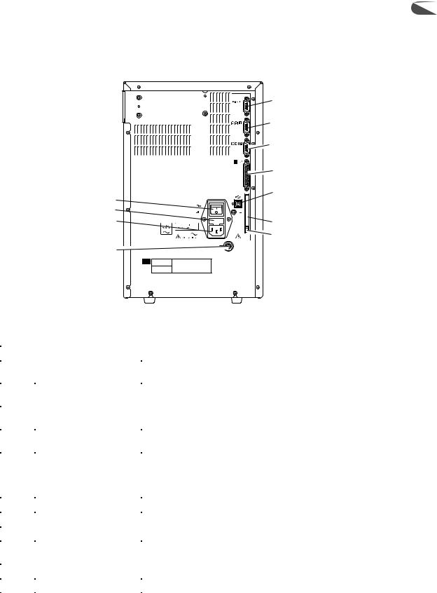
Rear Panel |
1 |
|
5 |
|
6 |
|
7 |
|
8 |
1 |
9 |
|
|
2 |
10 |
3 |
|
4 |
11 |
|
No. |
Name |
Description |
|
|
|
|
|
1 |
Main power switch |
Supplies the power to the analyzer when it is turned on. Under |
|
normal conditions keep this switch turned on. |
|||
|
|
||
2 |
Fuse holder |
Contains the time lag fuse. To replace the fuse, contact your |
|
Nihon Kohden representative. |
|||
|
|
||
3 |
AC SOURCE |
Connects the AC power cord to supply AC power to the analyzer. |
|
AC source socket |
|||
|
|
||
4 |
Equipotential ground |
Connects the ground lead to the equipotential ground terminal on |
|
terminal |
the wall for earth grounding. |
||
|
|||
|
|
Connects to the optional hand-held bar code reader. |
|
5 |
ZK-820V |
Supplies the power to the bar code reader when connected. |
|
Bar code reader socket |
Power supply voltage: 5 V DC (pin 9: 5 V, pin 5: GND) |
||
|
|||
|
|
Rated current: 200 mA |
|
6 |
Serial port 1 |
Connects to the optional WA-460V/461V card printer or PC. |
|
7 |
Serial port 2 |
Connects to the optional WA-460V/461V card printer or PC. |
|
8 |
Printer socket |
Connects to an external printer (WA-710V/712V or other). |
|
|
|
|
|
9 |
USB socket |
Connects to a PC. The optional Data Management Software |
|
needs to be installed on the PC to receive data from the analyzer. |
|||
|
|
||
10 |
Memory card socket |
Insert a memory card when you upgrade the software. |
|
11 |
Memory card eject button |
Press this button when you eject a memory card. |
Service Manual MEK-6400/6410/6420 |
1.9 |

1. GENERAL
Composition
MEK-6400
Standard
MEK-6400J MEK-6400K MEK-6400C
|
|
|
|
|
|
|
|
|
MC-640V |
|
|
Measuring Unit |
|
|
|
|
|
|||
|
|
|
|
|
|
|
|
|
|
|
|
|
|
|
|
|
|
|
UT-7198 |
MEASURING Board |
|
|
|
|
|
||
|
|
|
|
|
|
|
|
|
|
|
|
UT-7201 |
HGB AMP Board |
|
|
|
|
|
||
|
|
|
|
|
|
|
|
|
|
|
|
|
|
|
|
|
|
|
UT-7202 |
HGB LED Board |
|
|
|
|
|
||
|
|
|
|
|
|
2-Way Electromagnetic Value (× 10) |
|
|
|
|
|
XP-612V |
|
|
|
|
|
|
||
|
|
|
|
|
|
2-Way Electromagnetic Value (× 2) |
|
|
|
|
|
XP-602V |
|
|
|
|
|
|
||
|
|
|
|
|
|
|
|
|
MD-640V |
|
|
Combination Syringe Pump Unit |
|
|
|
|
|
|||
|
|
|
|
|
|
|
|
|
|
|
|
|
|
|
|
|
|
|
UT-7200 |
MIXED PUMP Board |
|
|
|
|
|
||
|
|
|
|
|
|
2-Way Electromagnetic Value (× 4) |
|
|
|
|
|
XP-612V |
|
|
|
|
|
|
||
|
|
|
|
|
|
|
|
|
MP-640V |
|
Pump Unit |
||
|
|
|
|
|||
|
|
|
|
|
|
|
|
|
PV-641VK |
|
Front Panel Unit |
||
|
|
|
|
|||
|
|
|
|
|
|
|
|
|
|
|
|
|
|
|
|
|
|
|
UT-7203 |
KEY Board |
|
|
|
|
|
||
|
|
|
|
|
|
|
|
|
|
|
|
|
|
|
|
JQ-640V |
|
Inlet/Outlet Unit |
||
|
|
|
|
|||
|
|
|
|
|
|
|
|
|
|
|
|
|
|
|
|
|
|
|
UT-7199 |
LIQUID SENSOR Board |
|
|
|
|
|
||
|
|
|
|
|
|
2-Way Electromagnetic Value (× 2) |
|
|
|
|
|
|
|
|
|
|
|
|
XP-612V |
|
|
|
|
|
|
||
|
|
|
|
|
|
|
|
|
JQ-641V |
|
Valve Unit |
||
|
|
|
|
|||
|
|
|
|
|
|
2-Way Electromagnetic Value (× 6) |
|
|
|
|
|
|
|
|
|
|
|
|
XP-612V |
|
|
|
|
|
|
||
|
|
|
|
|
|
|
|
|
MS-640V |
|
Sampler Unit |
||
|
|
|
|
|||
|
|
|
|
|
|
|
|
|
|
|
|
|
|
|
|
MS-641V |
|
|
Cap Pierce Unit |
|
|
|
|
|
|||
|
|
|
|
|
|
|
|
|
|
|
|
|
|
|
|
UT-7192 |
|
|
AMP CONTROL Board |
|
|
|
|
|
|||
|
|
|
|
|
|
|
|
|
|
|
|
||
|
|
UT-7193 |
|
|
POWER Board |
|
|
|
|
|
|||
|
|
|
|
|
|
|
Option
WA-640VK |
|
Printer Unit |
||
|
|
|
|
|
|
|
|
UT-7205 |
PRINTER DRIVER Board |
|
|
|
||
1.10 |
Service Manual MEK-6400/6410/6420 |

1. GENERAL
MEK-6410 |
1 |
Standard
MEK-6410J MEK-6410K MEK-6410C
|
|
|
|
|
|
|
|
|
MC-640V |
|
|
Measuring Unit |
|
|
|
|
|
|||
|
|
|
|
|
|
|
|
|
|
|
|
UT-7198 |
MEASURING Board |
|
|
|
|
|
||
|
|
|
|
|
|
|
|
|
|
|
|
UT-7201 |
HGB AMP Board |
|
|
|
|
|
||
|
|
|
|
|
|
|
|
|
|
|
|
UT-7202 |
HGB LED Board |
|
|
|
|
|
||
|
|
|
|
|
|
2-Way Electromagnetic Value (× 10) |
|
|
|
|
|
XP-612V |
|
|
|
|
|
|
||
|
|
|
|
|
|
2-Way Electromagnetic Value (× 2) |
|
|
|
|
|
XP-602V |
|
|
|
|
|
|
||
|
|
|
|
|
|
|
|
|
MD-640V |
|
|
Combination Syringe Pump Unit |
|
|
|
|
|
|||
|
|
|
|
|
|
|
|
|
|
|
|
UT-7200 |
MIXED PUMP Board |
|
|
|
|
|
||
|
|
|
|
|
|
2-Way Electromagnetic Value (× 4) |
|
|
|
|
|
XP-612V |
|
|
|
|
|
|
||
|
|
|
|
|
|
|
|
|
MP-640V |
|
Pump Unit |
||
|
|
|
|
|||
|
|
|
|
|
|
|
|
|
PV-641VK |
|
Front Panel Unit |
||
|
|
|
|
|||
|
|
|
|
|
|
|
|
|
|
|
|
UT-7203 |
KEY Board |
|
|
|
|
|
||
|
|
|
|
|
|
|
|
|
JQ-640V |
|
Inlet/Outlet Unit |
||
|
|
|
|
|||
|
|
|
|
|
|
|
|
|
|
|
|
UT-7199 |
LIQUID SENSOR Board |
|
|
|
|
|
||
|
|
|
|
|
|
2-Way Electromagnetic Value (× 2) |
|
|
|
|
|
XP-612V |
|
|
|
|
|
|
||
|
|
|
|
|
|
|
|
|
JQ-642V |
|
Valve Unit |
||
|
|
|
|
|||
|
|
|
|
|
|
2-Way Electromagnetic Value (× 4) |
|
|
|
|
|
XP-612V |
|
|
|
|
|
|
||
|
|
|
|
|
|
|
|
|
MS-640V |
|
Sampler Unit |
||
|
|
|
|
|||
|
|
|
|
|
|
|
|
|
|
|
|
|
|
|
|
MR-640V |
|
|
Rinse Unit |
|
|
|
|
|
|||
|
|
|
|
|
|
|
|
|
|
|
|
|
|
|
|
UT-71921 |
|
|
AMP CONTROL Board |
|
|
|
|
|
|||
|
|
|
|
|
|
|
|
|
|
|
|
||
|
|
UT-7193 |
|
|
POWER Board |
|
|
|
|
|
|||
|
|
|
|
|
|
|
Option
WA-640VK |
Printer Unit |
|
|
UT-7205 PRINTER DRIVER Board
Service Manual MEK-6400/6410/6420 |
1.11 |

1. GENERAL
MEK-6420
Standard
MEK-6420J MEK-6420K MEK-6420C
|
MC-640V |
|
Measuring Unit |
||
|
|
|
|
|
|
|
|
|
|
UT-7198 |
MEASURING Board |
|
|
|
|
||
|
|
|
|
|
|
|
|
|
|
UT-7201 |
HGB AMP Board |
|
|
|
|
||
|
|
|
|
|
|
|
|
|
|
UT-7202 |
HGB LED Board |
|
|
|
|
||
|
|
|
|
|
|
|
|
|
|
XP-612V |
2-Way Electromagnetic Value (x 10) |
|
|
|
|
||
|
|
|
|
|
|
|
|
|
|
XP-602V |
2-Way Electromagnetic Value (x 2) |
|
|
|
|
||
|
|
|
|
|
|
|
MD-640V |
|
|
Combination Syringe Pump Unit |
|
|
|
|
|||
|
|
|
|
|
|
|
|
|
|
UT-7200 |
MIXED PUMP Board |
|
|
|
|
||
|
|
|
|
|
|
|
|
|
|
XP-612V |
2-Way Electromagnetic Value (x 4) |
|
|
|
|
||
|
|
|
|
|
|
|
MP-640V |
|
Pump Unit |
||
|
|
|
|||
|
|
|
|
|
|
|
PV-641VK |
|
Front Panel Unit |
||
|
|
|
|||
|
|
|
|
|
|
|
|
|
|
UT-7203 |
KEY Board |
|
|
|
|
||
|
|
|
|
|
|
|
JQ-640V |
|
|
Inlet/Outlet Unit |
|
|
|
|
|||
|
|
|
|
|
|
|
|
|
|
UT-7199 |
LIQUID SENSOR Board |
|
|
|
|
||
|
|
|
|
|
|
|
|
|
|
XP-612V |
2-Way Electromagnetic Value (x 2) |
|
|
|
|
||
|
|
|
|
|
|
|
JQ-642V |
|
|
Valve Unit |
|
|
|
|
|||
|
|
|
|
|
|
|
|
|
|
XP-612V |
2-Way Electromagnetic Value (x 4) |
|
|
|
|
||
|
|
|
|
|
|
|
MS-640V |
|
|
Sampler Unit |
|
|
|
|
|||
|
|
|
|
|
|
|
|
|
|
|
|
|
MR-640V |
|
|
Rinse Unit |
|
|
|
|
|||
|
|
|
|
|
|
|
|
|
|
|
|
|
UT-71922 |
|
|
AMP CONTROL Board (MEK-6420J/K) |
|
|
|
|
|||
|
|
|
|
|
|
|
|
|
|
|
|
|
UT-71923 |
|
|
AMP CONTROL Board (MEK-6420C) |
|
|
|
|
|||
|
|
|
|
|
|
|
|
|
|||
|
UT-7193 |
|
|
POWER Board |
|
|
|
|
|||
|
|
|
|
|
|
Option
WA-640VK |
|
Printer Unit |
||
|
|
|
|
|
|
|
|
UT-7205 |
PRINTER DRIVER Board |
|
|
|
||
1.12 |
Service Manual MEK-6400/6410/6420 |

Interference Substances
1. GENERAL
1
WBC: High WBC
When WBC count is outside the measurable range, measure the sample in high dilution mode. If the WBC count is still outside the range, dilute the sample further.
Nucleated erythrocyte
Nucleated erythrocyte is detected as WBC and causes increase in WBC count.
Unlysed red cells
In some rare occasions, the RBC in the blood sample may not completely lyse and these non-lysed RBC may be detected as WBC and cause increase in WBC count.
Multiple myeloma
The precipitation of proteins in multiple myeloma patients may increase the WBC count.
Leukemia
WBC is fragile in leukemia patients and WBC may be destroyed during measurement. These WBC fragments may also interfere with WBC differential measurement.
Chemotherapy
Cytotoxic and immunosuppressive drugs cause low WBC count.
Cryoglobulins
Cryoglobulin may be increased in patients who are pregnant or have myeloma, cancer, leukemia, macroglobulinemia, lymphoproliferative disorders, metastatic tumors, autoimmune disorders, infections, aneurysm, thromboembolic phenomena, diabetes, etc, which cause increase in WBC, RBC or PLT counts and HGB concentration. In such cases, warm the blood sample to 37°C in a water bath for 30 minutes and measure the sample immediately.
RBC: Leukemia
An increase in WBC in leukemia patient causes increase in RBC.
Agglutinated RBC
Agglutinated RBC may decrease RBC count. This can be checked by abnormal MCH and MCHC values and examination of the stained blood film.
Cold agglutinins
IgM immunoglobulins which are elevated in clod agglutinin disease may decrease RBC and PLT counts and increase MCV.
Hemolysis
When RBC is hemolyzed, RBC is decreased.
HGB: Turbidity of the blood sample
Any physiologic and/or therapeutic factors may increase HGB. In such a case, determine the cause of turbidity and follow the appropriate method below.
1.Increased WBC
An extreme increase in WBC causes excessive light scatter. In these cases, measure manually. Centrifuge the diluted sample and measure the supernatant fluid with a spectrophotometer.
2.Increased lipids
The blood sample may be milky when there is excessive lipids. This may occur with hyperlipidemia, hyperproteinemia and hyperbilirubinemia. Accurate HGB measurement can be achieved by manual methods and a plasma blank.
3.Increased turbidity
When RBC are resistant to lysing, turbidity may increase causing increase in HGB. Observe if MCH and MCHC values are abnormal. HGB result affects MCH and MCHC result.
4.Fetal bloods
The mixing of fetal and maternal blood may increase HGB value.
Service Manual MEK-6400/6410/6420 |
1.13 |
1.GENERAL
5.High WBC levels
Turbidity of blood increases and the hemoglobin concentration becomes high if WBC level of the blood sample is high. MCH and MCHC levels also become high.
HCT: Agglutinated RBC
RBC agglutination may cause erroneous HCT and MCV values. Observe if MCH and MCHC values are abnormal. In such a case, measure manually.
MCV: Agglutinated RBC
RBC agglutination may cause erroneous HCT and MCV values. Observe if MCH and MCHC values are abnormal. In such a case, measure manually.
Excessive number of large PLT
Excessive number of large PLT and/or excessively high WBC may affect the MCV value. Check by careful examination of the stained blood film.
MCH: MCH is determined from HGB and RBC values. Therefore, the limitations for HGB and RBC also affect MCH value.
MCHC: MCHC is determined from HGB and HCT values. Therefore, the limitations for HGB and HCT also affect
|
MCHC value. |
RDW: |
RDW is determined from RBC value. Therefore, the limitations for RBC also affect RDW value. |
|
Agglutinated RBC |
|
Agglutinated RBC may decrease RBC count and erroneous RDW. This can be checked by abnormal MCH and |
|
MCHC values and examination of the stained blood film. |
|
Nutritional deficiency or blood transfusion |
|
Iron and/or cobalamin and/or folate deficiency may increase RDW. |
PLT: |
Very small fragments |
|
Very small RBC, RBC fragments and WBC fragments may be the cause in increased PLT count. |
|
Agglutinated RBC |
|
PLT may be trapped in the agglutinated RBC resulting in decrease in PLT. This can be checked by abnormal |
|
MCH and MCHC values and examination of the stained blood film. |
|
Very large PLT |
|
Large PLT may exceed the PLT threshold and might not be counted which results in low PLT count. |
|
Chemotherapy |
|
Cytotoxic and immunosuppressive drugs may increase the fragility of cells which may cause low PLT count. |
|
In such a case, measure manually. |
|
Hemolysis |
|
Hemolyzed specimens contain red cell stroma which may increase PLT count. |
|
Anticoagulated blood |
|
Blood anticoagulated with acid-citrate-dextrose may have clumped PLT which may cause decrease in PLT |
|
count. |
|
Agglutinated PLT |
|
Clumped PLT may decrease PLT count and/or increase WBC count. For such sample, collect the sample in |
|
sodium citrate anticoagulant and measure only PLT. The PLT result must be corrected for the sodium citrate |
|
dilution effect. |
MPV: |
Very large PLT |
|
Large PLT may exceed the PLT threshold and not be counted which results in low MPV. |
|
Very small fragments |
|
Very small RBC, RBC fragments and WBC fragments may interfere with MPV measurement. |
|
Agglutinated RBC |
|
PLT may be trapped in the agglutinated RBC resulting in erroneous MPV. This can be checked by abnormal |
|
MCH and MCHC values and examination of the stained blood film. |
1.14 |
Service Manual MEK-6400/6410/6420 |

1. GENERAL
Chemotherapy |
1 |
Cytotoxic and immunosuppressive drugs may affect MPV. In such a case, measure manually.
NOTE
Blood samples collected in EDTA do not maintain stable MPV because platelets swell
depending on the interval after collection and storage temperature.
WBC differential parameters are derived from the WBC count, therefore, the limitations for WBC also affect these parameters.
LY and LY%: Erythroblasts, certain parasites and RBC that are resistant to lysis may interfere with an accurate LY count.
MO and MO%: Large lymphocytes, atypical lymphocytes, blasts and excessive number of basophils may interfere with an accurate MO count.
GR and GR%: Excessive eosinophils, metamyelocytes, myelocytes, promyelocytes, blasts and plasma cells may interfere with an accurate GR count and GR%.
EO: Abnormal granules may interfere with an accurate EO count.
Service Manual MEK-6400/6410/6420 |
1.15 |

Section 2 |
Troubleshooting |
2 |
|
|
|
Check Procedure Flowchart ............................................................................................................................... |
2.4 |
|
Operating Condition and Blood Sample Checks ................................................................................................. |
2.5 |
|
Operating Condition Check ...................................................................................................................... |
2.5 |
|
Blood Sample Handling Check ................................................................................................................. |
2.5 |
|
Pre-dilution Sample Preparation Check .................................................................................................... |
2.5 |
|
Checking the Hematology Analyzer ................................................................................................................... |
2.7 |
|
Checking Background Noise .................................................................................................................... |
2.7 |
|
Measurement ................................................................................................................................. |
2.7 |
|
Parameter Data Check with Diluent ................................................................................................ |
2.7 |
|
Reducing Background Noise .......................................................................................................... |
2.8 |
|
Background Noise Problems .......................................................................................................... |
2.9 |
|
Checking the Reproducibility .................................................................................................................... |
2.9 |
|
Checking Procedure ....................................................................................................................... |
2.9 |
|
CV Values ..................................................................................................................................... |
2.10 |
|
Checking Accuracy ........................................................................................................................................... |
2.11 |
|
Checking Procedure ................................................................................................................................ |
2.11 |
|
Poor WBC Reproducibility ....................................................................................................................... |
2.11 |
|
Poor HGB Reproducibility ........................................................................................................................ |
2.12 |
|
Poor RBC Reproducibility ........................................................................................................................ |
2.13 |
|
Poor PLT Reproducibility ......................................................................................................................... |
2.14 |
|
Poor HCT or MCV Reproducibility ........................................................................................................... |
2.15 |
|
Solving Problems from Alarm Messages .......................................................................................................... |
2.16 |
|
A001: No diluent ........................................................................................................................... |
2.16 |
|
A005: No detergent ....................................................................................................................... |
2.16 |
|
A007: No lysing reagent ................................................................................................................ |
2.17 |
|
A009: WBC priming error ............................................................................................................... |
2.17 |
|
A010: RBC PRIMING ERROR ...................................................................................................... |
2.17 |
|
A021: WBC level 1 ........................................................................................................................ |
2.17 |
|
A022: WBC level 2 ........................................................................................................................ |
2.18 |
|
A023: WBC level 3 ........................................................................................................................ |
2.18 |
|
A024: WBC bubble 1 ..................................................................................................................... |
2.18 |
|
A025: WBC bubble 2 ..................................................................................................................... |
2.18 |
|
A026: WBC bubble 3 ..................................................................................................................... |
2.19 |
|
A027: WBC bubble 4 ..................................................................................................................... |
2.19 |
|
A029: WBC clog ............................................................................................................................ |
2.19 |
|
A030: WBC sample error ............................................................................................................... |
2.19 |
|
A031: WBC noise 2 ....................................................................................................................... |
2.20 |
|
A032: WBC noise 1 ....................................................................................................................... |
2.20 |
|
A036: WBC upper manometer dirty ............................................................................................... |
2.20 |
|
A037: WBC lower manometer dirty ................................................................................................ |
2.20 |
|
A041: RBC level 1 ........................................................................................................................ |
2.21 |
|
A042: RBC level 2 ........................................................................................................................ |
2.21 |
|
A043: RBC level 3 ........................................................................................................................ |
2.21 |
|
A044: RBC bubble 1 ...................................................................................................................... |
2.22 |
|
A045: RBC bubble 2 ...................................................................................................................... |
2.22 |
|
A046: RBC bubble 3 ...................................................................................................................... |
2.22 |
|
Service Manual MEK-6400/6410/6420 |
2.1 |
|
|
|
|
 Loading...