


 Loading...
User’s Guide
Part II
Bedside Monitor
BSM-6301/BSM-6501/BSM-6701
BSM-6000 series
BSM-6301A
BSM-6301K
BSM-6501A
BSM-6501K
BSM-6701A
BSM-6701K
0614-901229G

If you have any comments or suggestions on this manual, please contact us at: www.nihonkohden.com
Copyright Notice
The entire contents of this manual are copyrighted by Nihon Kohden. All rights are reserved. No part of this document may be reproduced, stored, or transmitted in any form or by any means (electronic, mechanical, photocopied, recorded, or otherwise) without the prior written permission of Nihon Kohden.
Trademark
The mark printed on the SD card that is used in this instrument is a trademark. The company name and model name are trademarks and registered trademarks of each company.

Contents
|
Conventions Used in this Manual and Instrument ............................................................... |
i |
|
Warnings, Cautions and Notes .................................................................................. |
i |
|
Related Documentation........................................................................................................ |
i |
|
Safety Standards................................................................................................................. |
ii |
|
Safety Information............................................................................................................... |
ii |
Section 1 |
ECG Monitoring..................................................................... |
1.1 |
|
General............................................................................................................................. |
1.3 |
|
Using the Output Signal from the ECG/BP OUT Socket.............................. |
1.4 |
|
Preparing for ECG Monitoring.......................................................................................... |
1.5 |
|
Preparation Flowchart............................................................................................ |
1.5 |
|
Number of Electrodes and Measuring Leads......................................................... |
1.5 |
|
Electrode Position.................................................................................................. |
1.5 |
|
3 Electrode Leads........................................................................................ |
1.5 |
|
6 Electrode Leads........................................................................................ |
1.6 |
|
Mason-Likar Modification............................................................................. |
1.7 |
|
Standard 12 Leads....................................................................................... |
1.8 |
|
Selecting Electrodes and Lead.............................................................................. |
1.8 |
|
Types of Electrodes and Lead...................................................................... |
1.9 |
|
Connecting Cables and Attaching Disposable Electrodes................................... |
1.10 |
|
Connecting the Electrode Cable to the Input Unit...................................... |
1.10 |
|
Attaching Disposable Electrodes to the Patient......................................... |
1.11 |
|
Monitoring ECG.............................................................................................................. |
1.12 |
|
ECG Information on the Home Screen................................................................. |
1.13 |
|
ECG Data Display................................................................................................ |
1.13 |
|
Measuring ST Level............................................................................................. |
1.14 |
|
Monitoring Arrhythmia.................................................................................................... |
1.15 |
|
General................................................................................................................. |
1.15 |
|
Arrhythmia Analysis Data Display.............................................................. |
1.16 |
|
Changing Arrhythmia Monitoring Settings............................................................ |
1.17 |
|
Turning Arrhythmia Analysis On or Off....................................................... |
1.17 |
|
Selecting Arrhythmia Analysis Leads......................................................... |
1.18 |
|
Selecting the Patient Type for QRS Detection............................................ |
1.18 |
|
Learning the ECG Waveform for Arrhythmia Detection (VPC Learning).... |
1.19 |
|
Checking the Dominant QRS..................................................................... |
1.20 |
|
Changing ECG Settings................................................................................................. |
1.22 |
|
Changing the Monitoring Lead............................................................................. |
1.23 |
|
Optimum Lead............................................................................................ |
1.23 |
|
Selecting the Number of ECG Traces on the Home Screen...................... |
1.24 |
|
Changing a Lead........................................................................................ |
1.24 |
|
Assigning Va and Vb (Ca and Cb) Leads when Monitoring with 6 |
|
|
Electrodes.................................................................................................. |
1.25 |
|
Auto Lead Change On or Off..................................................................... |
1.26 |
|
Changing the ECG Sensitivity.............................................................................. |
1.26 |
1
2
3
4
4-1
4-2
4-3
5
6
7
8
9
10
11
12
13
14
15
16
17
User’s Guide Part II BSM-6000 |
C.1 |
CONTENTS |
|
Changing the Heart Rate/Pulse Rate, VPC and ST Alarm Limits........................ |
1.28 |
Changing Arrhythmia Alarm Settings................................................................... |
1.29 |
Changing the ST Alarm Limits............................................................................. |
1.32 |
Changing the ST Level Measurement Condition.................................................. |
1.33 |
Changing Pacing Settings.................................................................................... |
1.37 |
Turning Pacing Spike Detection On or Off................................................. |
1.37 |
Displaying Pacing Mark.............................................................................. |
1.38 |
Changing the Number of Electrodes.................................................................... |
1.38 |
Selecting Mode for Updating the Heart Rate....................................................... |
1.39 |
Selecting the Filter Type....................................................................................... |
1.39 |
Turning the Hum Filter On or Off.......................................................................... |
1.40 |
Changing the Sync Sound Source....................................................................... |
1.40 |
Selecting Sync Sound Pitch................................................................................. |
1.42 |
Use with an Electrosurgical Unit..................................................................................... |
1.44 |
Section 2 |
Respiration Monitoring......................................................... |
2.1 |
|
General............................................................................................................................. |
2.2 |
|
Measurement Method............................................................................................ |
2.2 |
|
Impedance Method...................................................................................... |
2.2 |
|
Thermistor Method....................................................................................... |
2.3 |
|
Preparing for Respiration Monitoring in Impedance Method............................................ |
2.3 |
|
Preparation Flowchart............................................................................................ |
2.3 |
|
Electrode Position and Waveform Examples.......................................................... |
2.4 |
|
Electrode Position........................................................................................ |
2.5 |
|
Amplitude..................................................................................................... |
2.5 |
|
Connecting Cables and Attaching Disposable Electrodes..................................... |
2.6 |
|
Preparing for Respiration Monitoring in Thermistor Method............................................. |
2.6 |
|
Preparation Flowchart............................................................................................ |
2.6 |
|
Respiration Pickups................................................................................................ |
2.6 |
|
Connecting the Cable to the Unit........................................................................... |
2.7 |
|
Attaching the Respiration Pickup........................................................................... |
2.7 |
|
When Using Respiration Pickup for Nose.................................................... |
2.7 |
|
When Using Respiration Pickup for Airway.................................................. |
2.7 |
|
Monitoring Respiration..................................................................................................... |
2.8 |
|
Respiration Information on the Home Screen........................................................ |
2.8 |
|
Changing Respiration Settings....................................................................................... |
2.10 |
|
Changing the Monitoring Lead in Impedance Method......................................... |
2.10 |
|
Changing the Respiration Sensitivity.................................................................... |
2.11 |
|
Turning Respiration Measurement On or Off in Impedance Method.................... |
2.12 |
|
Changing the Respiration Rate and Apnea Alarm Limits..................................... |
2.13 |
|
Changing the Respiration Waveform Sweep Speed............................................ |
2.14 |
Section 3 |
CO2 Monitoring...................................................................... |
3.1 |
|
General............................................................................................................................. |
3.2 |
|
Mainstream Method............................................................................................... |
3.2 |
|
Sidestream Method................................................................................................ |
3.3 |
|
Measurement Error with the TG-900P or TG-920P CO2 Sensor Kit....................... |
3.3 |
C.2 |
User’s Guide Part II |
BSM-6000 |

|
CONTENTS |
Use with Volatile Anesthetic Agents....................................................................... |
3.5 |
Preparing for CO2 Monitoring........................................................................................... |
3.6 |
Preparation Flowchart............................................................................................ |
3.6 |
Mainstream Method..................................................................................... |
3.6 |
Sidestream Method...................................................................................... |
3.6 |
Types of CO2 Sensor Kits for Mainstream Method................................................. |
3.8 |
TG-900P CO2 Sensor Kit........................................................................... |
3.10 |
TG-920P CO2 Sensor Kit........................................................................... |
3.10 |
TG-950P CO2 Sensor Kit........................................................................... |
3.12 |
TG-970P CO2 Sensor Kit........................................................................... |
3.12 |
Connecting the CO2 Sensor Kit to the Unit.......................................................... |
3.13 |
Connecting the CO2 Sensor Kit to the Respiration Circuit.................................... |
3.13 |
Performing Zero Calibration when Using a TG-950P or TG-970P CO2 Sensor |
|
Kit......................................................................................................................... |
3.13 |
Calibrating by Air........................................................................................ |
3.14 |
Calibrating with N2 Gas.............................................................................. |
3.15 |
Monitoring CO2 ............................................................................................................... |
3.16 |
CO2 Information on the Home Screen.................................................................. |
3.17 |
Changing CO2 Settings.................................................................................................. |
3.19 |
Changing the Scale.............................................................................................. |
3.19 |
Changing the CO2, Respiration Rate and Apnea Alarm Limits............................ |
3.20 |
Setting the Inspiration Composition...................................................................... |
3.21 |
Changing the CO2 Waveform Sweep Speed........................................................ |
3.22 |
Inspection of Measuring Accuracy................................................................................. |
3.23 |
Daily Inspection of Measuring Accuracy.............................................................. |
3.23 |
Inspection of Measuring Accuracy (Precise Method)........................................... |
3.23 |
1
2
3
4
4-1
4-2
4-3
5
6
7
8
9
10
11
12
Section 4 |
SpO2 Monitoring.................................................................... |
4.1 |
13 |
Section 4-1 |
SpO2 Monitoring on AY-660P/661P/663P/671P/673P Input Unit...... |
4.1.1 |
|
|
General.......................................................................................................................... |
4.1.2 |
14 |
|
When Monitoring Dual SpO2 ..................................................................... |
4.1.4 |
|
|
Silencing SpO2 Alarm................................................................................ |
4.1.4 |
15 |
|
Preparing for SpO2 Monitoring...................................................................................... |
4.1.5 |
16 |
|
Preparation Flowchart......................................................................................... |
4.1.5 |
|
|
Selecting a Probe................................................................................................ |
4.1.5 |
17 |
|
Nihon Kohden Reusable Probes |
4.1.5 |
|
|
|
||
|
Nihon Kohden Disposable Probes............................................................ |
4.1.6 |
|
|
Connecting Cables and Attaching the Probes..................................................... |
4.1.7 |
|
|
Connecting Cable to the Unit.................................................................... |
4.1.7 |
|
|
Attaching the Probe to the Patient............................................................ |
4.1.8 |
|
|
Monitoring SpO2 ............................................................................................................ |
4.1.9 |
|
|
SpO2 Information on the Home Screen............................................................... |
4.1.9 |
|
|
Changing SpO2 Settings.............................................................................................. |
4.1.10 |
|
|
Changing the Sensitivity.................................................................................... |
4.1.11 |
|
|
Changing the SpO2 and Pulse Rate Alarm Limits............................................. |
4.1.11 |
|
|
Changing the Sync Sound Source.................................................................... |
4.1.13 |
|
|
Selecting Sync Sound Pitch.............................................................................. |
4.1.14 |
|
|
Selecting the Response Mode.......................................................................... |
4.1.15 |
|
User’s Guide Part II |
BSM-6000 |
C.3 |
|
CONTENTS |
|
|
|
Selecting SpO2 Sensitivity Mode....................................................................... |
4.1.16 |
|
Displaying Pulse Rate and DSpO2 on the Home Screen................................... |
4.1.17 |
Section 4-2 |
SpO2 Monitoring on AY-651P/653P Input Unit.................................. |
4.2.1 |
|
General.......................................................................................................................... |
4.2.2 |
|
Silencing SpO2 Alarm................................................................................ |
4.2.4 |
|
When Monitoring Dual SpO2 .................................................................... |
4.2.4 |
|
Preparing for SpO2 Monitoring...................................................................................... |
4.2.6 |
|
Preparation Flowchart......................................................................................... |
4.2.6 |
|
Selecting a Probe................................................................................................ |
4.2.6 |
|
Nellcor SpO2 Probes................................................................................. |
4.2.6 |
|
Connecting Cables and Attaching the Probes..................................................... |
4.2.7 |
|
Connecting Cable to the Unit.................................................................... |
4.2.7 |
|
SpO2 Measurement at Two Sites............................................................... |
4.2.8 |
|
Attaching the Probe to the Patient............................................................ |
4.2.8 |
|
Monitoring SpO2 ............................................................................................................ |
4.2.9 |
|
SpO2 Information on the Home Screen............................................................... |
4.2.9 |
|
Changing SpO2 Settings.............................................................................................. |
4.2.10 |
|
Changing the Sensitivity.................................................................................... |
4.2.10 |
|
Changing the SpO2 and Pulse Rate Alarm Limits............................................. |
4.2.11 |
|
Changing the Sync Sound Source.................................................................... |
4.2.13 |
|
Selecting Sync Sound Pitch.............................................................................. |
4.2.14 |
|
Displaying Pulse Rate and DSpO2 on the Home Screen................................... |
4.2.15 |
Section 4-3 |
SpO2 Monitoring on AY-631P/633P Input Unit.................................. |
4.3.1 |
|
General.......................................................................................................................... |
4.3.2 |
|
Silencing SpO2 Alarm................................................................................ |
4.3.4 |
|
When Monitoring Dual SpO2 .................................................................... |
4.3.4 |
|
Preparing for SpO2 Monitoring...................................................................................... |
4.3.6 |
|
Preparation Flowchart......................................................................................... |
4.3.6 |
|
Selecting a Probe and Patient Cable................................................................... |
4.3.6 |
|
Masimo SpO2 Probes................................................................................ |
4.3.7 |
|
SpO2 Connection Cords............................................................................ |
4.3.8 |
|
Connecting Cables and Attaching the Probes..................................................... |
4.3.8 |
|
Connecting Cable to the Unit.................................................................... |
4.3.8 |
|
SpO2 Measurement at Two Sites............................................................... |
4.3.9 |
|
Attaching the Probe to the Patient............................................................ |
4.3.9 |
|
Monitoring SpO2 .......................................................................................................... |
4.3.10 |
|
SpO2 Information on the Home Screen............................................................. |
4.3.10 |
|
SpO2 Information on the SpO2 Window............................................................. |
4.3.11 |
|
Signal IQ................................................................................................. |
4.3.11 |
|
PI (Perfusion Index)................................................................................. |
4.3.11 |
|
SpO2 Information on the SpO2-2 Window.......................................................... |
4.3.12 |
|
Changing SpO2 Settings.............................................................................................. |
4.3.13 |
|
Changing the Sensitivity.................................................................................... |
4.3.14 |
|
Changing the SpO2 and Pulse Rate Alarm Limits............................................. |
4.3.14 |
|
Changing the Sync Sound Source.................................................................... |
4.3.16 |
|
Selecting Sync Sound Pitch.............................................................................. |
4.3.17 |
|
Selecting the Averaging Time............................................................................ |
4.3.19 |
C.4 |
User’s Guide Part II |
BSM-6000 |

|
|
CONTENTS |
|
Selecting the Sensitivity Mode.......................................................................... |
4.3.19 |
|
Turning FAST SAT Mode On or Off................................................................... |
4.3.20 |
|
Displaying Pulse Rate, DSpO2 and Perfusion Index (PI) on the Home |
|
|
Screen............................................................................................................... |
4.3.21 |
Section 5 |
NIBP Monitoring.................................................................... |
5.1 |
|
General............................................................................................................................. |
5.2 |
|
Preparing for NIBP Measurement.................................................................................... |
5.3 |
|
Preparation Flowchart............................................................................................ |
5.3 |
|
Selecting the Cuff................................................................................................... |
5.3 |
|
Types of Cuffs......................................................................................................... |
5.4 |
|
Reusable Cuffs............................................................................................. |
5.4 |
|
Disposable Cuffs.......................................................................................... |
5.5 |
|
Connecting Cables and Attaching the Cuff to the Patient...................................... |
5.6 |
|
Connecting Air Hose and Cuff to the Unit.................................................... |
5.6 |
|
Attaching the Cuff to the Patient.................................................................. |
5.8 |
|
Measuring and Monitoring NIBP.................................................................................... |
5.10 |
|
Measurement Mode and Interval......................................................................... |
5.10 |
|
Manual Measurement................................................................................ |
5.11 |
|
Auto Measurement..................................................................................... |
5.11 |
|
Auto Measurement with PWTT.................................................................. |
5.11 |
|
STAT Measurement.................................................................................... |
5.13 |
|
SIM Mode Measurement............................................................................ |
5.13 |
|
NIBP Information on the Home Screen................................................................ |
5.14 |
|
Dimming and Hiding the NIBP Data........................................................... |
5.14 |
|
Performing NIBP Measurement........................................................................... |
5.15 |
|
Manual Measurement................................................................................ |
5.15 |
|
Auto Measurement..................................................................................... |
5.16 |
|
Auto Measurement with PWTT.................................................................. |
5.17 |
|
STAT Measurement.................................................................................... |
5.18 |
|
SIM Mode Measurement............................................................................ |
5.20 |
|
Changing NIBP Settings................................................................................................. |
5.23 |
|
Selecting the Initial Cuff Inflation Pressure.......................................................... |
5.23 |
|
Selecting the Initial Cuff Inflation Pressure Type........................................ |
5.23 |
|
Setting the Cuff Inflation Pressure............................................................. |
5.24 |
|
Changing the NIBP Alarm Limits.......................................................................... |
5.25 |
|
Changing the PWTT Settings............................................................................... |
5.26 |
|
Using Venous Puncture Mode........................................................................................ |
5.28 |
Section 6 |
IBP Monitoring....................................................................... |
6.1 |
|
General............................................................................................................................. |
6.2 |
|
Preparing for Blood Pressure Monitoring......................................................................... |
6.4 |
|
Preparation Flowchart............................................................................................ |
6.4 |
|
Selecting the Blood Pressure Measuring Device................................................... |
6.4 |
|
Blood Pressure Transducers........................................................................ |
6.5 |
|
IBP Connection Cords................................................................................. |
6.6 |
|
JP-940P IBP Connection Box...................................................................... |
6.6 |
User’s Guide Part II |
BSM-6000 |
C.5 |
1
2
3
4
4-1
4-2
4-3
5
6
7
8
9
10
11
12
13
14
15
16
17
CONTENTS |
|
Installing the Blood Pressure Measuring Device.................................................... |
6.7 |
Connecting Cables to the Unit..................................................................... |
6.7 |
Assembling the Transducer.......................................................................... |
6.8 |
Adjusting Zero Balance........................................................................................ |
6.10 |
Zero Balance Mode.................................................................................... |
6.10 |
Adjusting Zero Balance.............................................................................. |
6.10 |
Memorizing the Zero Balance Values........................................................ |
6.12 |
The CHECK ZERO Page........................................................................... |
6.13 |
Monitoring IBP................................................................................................................ |
6.14 |
IBP Information on the Home Screen................................................................... |
6.14 |
Changing IBP Settings................................................................................................... |
6.16 |
Changing the Label.............................................................................................. |
6.16 |
Types of Labels.......................................................................................... |
6.17 |
Changing the Labels.................................................................................. |
6.17 |
Changing the Scale.............................................................................................. |
6.18 |
Changing the IBP and Pulse Rate Alarm Limits................................................... |
6.19 |
Selecting the Mode for Calculating IBP................................................................ |
6.21 |
Selecting the Data Display Mode on the Home Screen....................................... |
6.21 |
Displaying CPP On or Off..................................................................................... |
6.22 |
Changing the Sync Sound Source....................................................................... |
6.22 |
Selecting Sync Sound Pitch................................................................................. |
6.24 |
Selecting the IBP Waveform Display Mode.......................................................... |
6.25 |
Displaying PPV or SPV on the Home Screen...................................................... |
6.25 |
Selecting PPV or SPV Display on the Home Screen................................. |
6.25 |
Changing PPV or SPV Average Time.................................................................. |
6.27 |
Section 7 |
Temperature Monitoring........................................................ |
7.1 |
|
General............................................................................................................................. |
7.2 |
|
Preparing for Temperature Monitoring.............................................................................. |
7.3 |
|
Preparation Flowchart............................................................................................ |
7.3 |
|
Selecting the Probe................................................................................................ |
7.3 |
|
Reusable Probes.......................................................................................... |
7.3 |
|
Disposable Probes....................................................................................... |
7.4 |
|
Temperature Connection Cord..................................................................... |
7.4 |
|
Connecting Cables and Attaching the Probe......................................................... |
7.5 |
|
Connecting Cable to the Unit....................................................................... |
7.5 |
|
Attaching the Probe to the Patient............................................................... |
7.6 |
|
Using the Insulation Pad.............................................................................. |
7.6 |
|
Monitoring Temperature.................................................................................................... |
7.7 |
|
Temperature Information on the Home Screen...................................................... |
7.7 |
|
Changing Temperature Settings....................................................................................... |
7.8 |
|
Changing the Label................................................................................................ |
7.8 |
|
Types of Labels............................................................................................ |
7.8 |
|
Types of Labels for Blood Temperature Measured Regions......................... |
7.9 |
|
Changing the Label...................................................................................... |
7.9 |
|
Setting the Site for Calculating Temperature Difference....................................... |
7.10 |
|
Changing the Temperature Alarm Limits.............................................................. |
7.10 |
C.6 |
User’s Guide Part II BSM-6000 |

|
CONTENTS |
|
Section 8 |
BIS Monitoring....................................................................... |
8.1 |
|
General............................................................................................................................. |
8.2 |
|
List of Terms........................................................................................................... |
8.2 |
|
Preparing for BIS Monitoring............................................................................................ |
8.3 |
|
Preparation Flowchart for Using the BIS Processor............................................... |
8.3 |
|
Preparation Flowchart for Using the BIS Monitor................................................... |
8.4 |
|
Monitoring BIS.................................................................................................................. |
8.5 |
|
BIS Information on the Home Screen..................................................................... |
8.8 |
|
BIS Information on the BIS Window....................................................................... |
8.9 |
|
Changing the BIS Settings............................................................................................. |
8.10 |
|
Checking the Impedance of the BIS Sensor........................................................ |
8.10 |
|
Automatically Checking Impedance........................................................... |
8.11 |
|
Manually Checking Impedance.................................................................. |
8.11 |
|
Changing the BIS Alarm Limits............................................................................ |
8.12 |
|
Changing the Sensitivity....................................................................................... |
8.13 |
|
Turning the Filter On or Off................................................................................... |
8.13 |
|
Selecting the BIS Average Time (Smoothing Rate).............................................. |
8.14 |
|
Changing the EEG Waveform Sweep Speed....................................................... |
8.14 |
|
Selecting the Second Current Trendgraph........................................................... |
8.15 |
Section 9 |
Cardiac Output Monitoring................................................... |
9.1 |
|
General............................................................................................................................. |
9.2 |
|
Preparing for Cardiac Output Monitoring.......................................................................... |
9.3 |
|
Preparation Flowchart............................................................................................ |
9.3 |
|
Selecting the Catheter............................................................................................ |
9.3 |
|
Types of Catheter......................................................................................... |
9.3 |
|
Preparing the Injectate........................................................................................... |
9.4 |
|
Usable Injectate........................................................................................... |
9.4 |
|
Injectate Temperature and Volume............................................................... |
9.4 |
|
Measuring the Injectate Temperature........................................................... |
9.5 |
|
Assembling the Measuring System........................................................................ |
9.7 |
|
Connecting Cables to the Unit..................................................................... |
9.7 |
|
Measuring System Setup Examples............................................................ |
9.8 |
|
Changing Settings for CO Measurement........................................................................ |
9.10 |
|
Setting the Coefficient Value................................................................................ |
9.10 |
|
Procedure.................................................................................................. |
9.10 |
|
The Preset Coefficient Value Settings........................................................ |
9.12 |
|
Changing the Height and Weight.......................................................................... |
9.13 |
|
Changing the Blood Temperature Alarm Setting.................................................. |
9.14 |
|
Measuring the Pulmonary Capillary Wedge Pressure.................................................... |
9.16 |
|
Inserting and Retaining the Catheter in the Patient............................................. |
9.16 |
|
Inserting Position and Inserting Method..................................................... |
9.16 |
|
Inserting the Catheter into the Patient and Monitoring Blood Pressure..... |
9.16 |
|
Entering the Pulmonary Capillary Wedge Pressure and Other IBP Values.......... |
9.18 |
|
Measuring CO................................................................................................................ |
9.19 |
|
Before Measurement............................................................................................ |
9.19 |
|
Measuring CO...................................................................................................... |
9.19 |
|
When Measurements Cannot be Performed Correctly.............................. |
9.21 |
User’s Guide Part II |
BSM-6000 |
C.7 |
1
2
3
4
4-1
4-2
4-3
5
6
7
8
9
10
11
12
13
14
15
16
17
CONTENTS |
|
Deleting the Data from the CO Table ................................................................... |
9.22 |
Recording Hemodynamics Data........................................................................... |
9.22 |
Registering Acquired Data to the Hemodynamics Table on the TREND |
|
Window................................................................................................................. |
9.23 |
Explanation of Hemodynamics Data.......................................................... |
9.24 |
CO Value Calculation Equation/Coefficient Value Calculation Value.............................. |
9.25 |
Section 10 |
Gas Monitoring.................................................................... |
10.1 |
|
General........................................................................................................................... |
10.2 |
|
Measuring Parameters......................................................................................... |
10.3 |
|
Preparing for Gas Monitoring......................................................................................... |
10.4 |
|
Preparation Flowchart for Using the Multigas Unit............................................... |
10.4 |
|
Preparation Flowchart for Using the Dräger Medical Primus/Fabius® |
|
|
Anesthesia Workstation........................................................................................ |
10.4 |
|
Monitoring Gas............................................................................................................... |
10.5 |
|
Gas Information on the Home Screen.................................................................. |
10.6 |
|
Gas Information on the GAS Window................................................................... |
10.8 |
|
Changing Gas Settings.................................................................................................. |
10.9 |
|
Changing the Respiration Rate, Apnea and Gas Alarm Limits.......................... |
10.10 |
|
Changing the Waveform Scale........................................................................... |
10.12 |
|
Changing the Sampling Rate............................................................................. |
10.13 |
|
Performing Zero Calibration............................................................................... |
10.14 |
|
Turning Gas Measurement On or Off ................................................................ |
10.15 |
|
Selecting the Parameters to be Displayed on the Home Screen....................... |
10.16 |
|
Performing Gas Calibration.......................................................................................... |
10.17 |
Section 11 |
O2 Monitoring....................................................................... |
11.1 |
|
General........................................................................................................................... |
11.2 |
|
Preparing for O2 Monitoring............................................................................................ |
11.3 |
|
Preparation Flowchart.......................................................................................... |
11.3 |
|
Oxygen Sensor and Connection Cord................................................................. |
11.3 |
|
Connecting the Oxygen Sensor to the Unit.......................................................... |
11.3 |
|
Calibrating the O2 Sensor..................................................................................... |
11.4 |
|
Calibration with Air (Simple method).......................................................... |
11.4 |
|
Calibration with 100% O2 (Precise Method)............................................... |
11.5 |
|
Connecting the Oxygen Sensor to the Inspiration Circuit and Starting |
|
|
Measurement....................................................................................................... |
11.7 |
|
Monitoring O2 ................................................................................................................. |
11.8 |
|
O2 Information on the Home Screen.................................................................... |
11.8 |
|
Changing O2 Settings..................................................................................................... |
11.9 |
|
Changing the O2 Alarm Limits.............................................................................. |
11.9 |
|
Principle and Structure of Oxygen Sensor................................................................... |
11.10 |
|
Structure of Oxygen Sensor............................................................................... |
11.10 |
|
Life Span of Oxygen Sensor.............................................................................. |
11.10 |
|
Precautions when Using the Oxygen Sensor..................................................... |
11.11 |
C.8 |
User’s Guide Part II BSM-6000 |
CONTENTS
Section 12 |
Ventilator Monitoring........................................................... |
12.1 |
1 |
|
General........................................................................................................................... |
12.2 |
2 |
|
Monitoring Parameters and Settings |
12.2 |
|
|
|
||
|
Preparing for Ventilator Parameter Monitoring................................................................ |
12.3 |
3 |
|
Monitoring Ventilator Parameters |
12.4 |
|
|
|
||
|
Ventilator Information on the Home Screen......................................................... |
12.5 |
4 |
|
Ventilator Information on the VENT Window |
12.5 |
|
|
|
||
|
Changing Ventilator Settings.......................................................................................... |
12.6 |
4-1 |
|
Checking the Ventilator Settings |
12.6 |
|
|
|
||
|
Changing the FLOW and Paw Scale.................................................................... |
12.7 |
4-2 |
|
|
|
|
|
Selecting the Ventilator Parameters to be Displayed on the Home Screen.......... |
12.7 |
|
|
|
|
4-3 |
Section 13 |
TOF Monitoring.................................................................... |
13.1 |
5 |
|
General........................................................................................................................... |
13.2 |
6 |
|
List of Terms |
13.2 |
|
|
|
||
|
Preparing for TOF Monitoring......................................................................................... |
13.3 |
7 |
|
Monitoring TOF |
13.4 |
|
|
|
||
|
TOF Information on the Home Screen................................................................. |
13.4 |
8 |
|
Opening the TOF Window |
13.4 |
|
|
|
||
|
TOF Information on the TOF Window................................................................... |
13.5 |
9 |
|
Recording the TOF Data |
13.5 |
|
|
|
||
|
|
|
10 |
Section 14 CCO Monitoring................................................................... |
14.1 |
CCO Monitoring by CCO Monitor................................................................................... |
14.2 |
General................................................................................................................. |
14.2 |
List of Terms............................................................................................... |
14.2 |
Preparing for CCO Monitoring.............................................................................. |
14.3 |
Monitoring CCO................................................................................................... |
14.3 |
CCO Information on the Home Screen...................................................... |
14.3 |
CCO Information on the CCO Window....................................................... |
14.4 |
Opening the CCO Window......................................................................... |
14.4 |
Hemodynamics Table on the HEMO Page of the TREND Window............ |
14.4 |
Changing the CCO Settings................................................................................. |
14.5 |
Selecting the CCO Parameters to be Displayed on the Home Screen...... |
14.5 |
PCCO Monitoring by PiCCO plus or PiCCO2 Monitor................................................... |
14.6 |
General................................................................................................................. |
14.6 |
List of Terms............................................................................................... |
14.7 |
Monitoring Parameters and Settings.......................................................... |
14.8 |
Preparing for PiCCO Monitoring........................................................................... |
14.9 |
Monitoring PiCCO................................................................................................ |
14.9 |
PiCCO Information on the Home Screen................................................... |
14.9 |
PiCCO Information on the MEASURE page of CCO Window.................. |
14.10 |
Recording the PiCCO Data on the WAVEFORM Page of CCO |
|
Window.................................................................................................... |
14.11 |
Hemodynamics Table on the HEMO Page of the TREND Window.......... |
14.12 |
Changing the PiCCO Setting............................................................................. |
14.12 |
11
12
13
14
15
16
17
User’s Guide Part II BSM-6000 |
C.9 |
|
|
|
Changing the Scale of the AP Waveform on the WAVEFORM Page |
|
||||||||||
|
|
|
CCO Window........................................................................................... |
14.12 |
||||||||||
|
|
|
Selecting the Absolute or Index Value to be Displayed............................ |
14.13 |
||||||||||
|
|
|
|
|
|
|
|
|
|
|
|
|
|
|
|
CCO/SvO |
2 Monitoring by SO2/CCO Monitor................................................................ |
14.14 |
|||||||||||
|
General............................................................................................................... |
14.14 |
||||||||||||
|
|
|
List of Terms............................................................................................. |
14.14 |
||||||||||
|
|
|
|
|
|
|
|
|
2 Monitoring |
|
||||
|
Preparing for CCO/SvO |
|
14.15 |
|||||||||||
|
|
|
|
|
|
|
|
|
|
|
||||
|
Monitoring CCO/SvO |
2 |
....................................................................................... |
|
|
14.15 |
||||||||
|
|
|
CCO Information on the Home Screen.................................................... |
14.15 |
||||||||||
|
|
|
|
|
2 Information on the CCO Window |
14.16 |
||||||||
|
|
|
CCO/SvO |
|||||||||||
|
|
|
Opening the CCO Window....................................................................... |
14.16 |
||||||||||
|
|
|
Hemodynamics Table on the HEMO Page of the TREND Window.......... |
14.16 |
||||||||||
|
|
|
2 Settings |
14.17 |
||||||||||
|
Changing the CCO/SvO |
|||||||||||||
|
|
|
|
|
2 Parameters to be Displayed on the Home |
|
||||||||
|
|
|
Selecting the CCO/SvO |
|
||||||||||
|
|
|
Screen...................................................................................................... |
14.17 |
||||||||||
|
Explanation of Hemodynamics Data............................................................................ |
14.18 |
||||||||||||
Section 15 |
FLOW/Paw Monitoring......................................................... |
15.1 |
||||||||||||
|
General........................................................................................................................... |
15.2 |
||||||||||||
|
List of Terms......................................................................................................... |
15.2 |
||||||||||||
|
Preparing for FLOW/Paw Monitoring.............................................................................. |
15.3 |
||||||||||||
|
Preparation Flowchart.......................................................................................... |
15.3 |
||||||||||||
|
Monitoring FLOW/Paw.................................................................................................... |
15.4 |
||||||||||||
|
FLOW/Paw Information on the Home Screen...................................................... |
15.4 |
||||||||||||
|
FLOW/Paw Information on the FLOW/Paw Window............................................. |
15.5 |
||||||||||||
|
Changing FLOW/Paw Settings....................................................................................... |
15.6 |
||||||||||||
|
Changing the MV, Ppeak, PEEP, Respiration Rate and Apnea Alarm Limits....... |
15.6 |
||||||||||||
|
Changing the Scale.............................................................................................. |
15.8 |
||||||||||||
|
Setting the Inspired Gas Composition.................................................................. |
15.8 |
||||||||||||
|
Setting the Temperature and Humidity of the Inspired Gas................................ |
15.10 |
||||||||||||
|
Selecting the FLOW/Paw Parameters to be Displayed on the Home Screen.... |
15.10 |
||||||||||||
|
Turning FLOW/Paw Measurement On or Off...................................................... |
15.11 |
||||||||||||
|
Viewing the Loops........................................................................................................ |
15.12 |
||||||||||||
|
Displaying the Loop Window.............................................................................. |
15.12 |
||||||||||||
|
Changing the Loop Graph Scale........................................................................ |
15.13 |
||||||||||||
|
Registering Reference Loops............................................................................. |
15.14 |
||||||||||||
|
Turning Reference Loop Display On or Off........................................................ |
15.17 |
||||||||||||
|
Changing the Loop Graph Scale on the REFERENCE Tab............................... |
15.18 |
||||||||||||
|
Recording the Loops on the FLOW/Paw Window.............................................. |
15.19 |
||||||||||||
|
Changing the Loop Settings............................................................................... |
15.20 |
||||||||||||
|
|
|
Selecting the Loop Types to Display on the Home Screen...................... |
15.20 |
||||||||||
|
|
|
Selecting the Number of Displayed Loops............................................... |
15.21 |
||||||||||
Section 16 |
EEG Monitoring................................................................... |
16.1 |
||||||||||||
|
General........................................................................................................................... |
16.2 |
||||||||||||
|
List of Terms......................................................................................................... |
16.2 |
||||||||||||
|
Preparing for EEG Monitoring........................................................................................ |
16.3 |
||||||||||||
C.10 |
|
|
|
|
|
|
|
|
|
|
|
|
User’s Guide Part II BSM-6000 |
|

Monitoring EEG.............................................................................................................. |
16.4 |
1 |
|
EEG Information on the Home Screen................................................................. |
16.4 |
|
|
EEG Information on the EEG Window.................................................................. |
16.5 |
2 |
|
Returning EEG Waveforms to the Baseline............................................... |
16.5 |
|
|
Displaying the Calibration Waveforms........................................................ |
16.5 |
3 |
|
Changing the EEG Settings........................................................................................... |
16.6 |
4 |
|
Setting Montage................................................................................................... |
16.6 |
||
Checking the Electrode Impedance..................................................................... |
16.8 |
4-1 |
|
Automatically Checking Impedance |
16.8 |
||
|
|||
Manually Checking Impedance.................................................................. |
16.8 |
4-2 |
|
Changing the SEF and TP Alarm Limits |
16.10 |
||
|
|||
Changing the EEG Sensitivity............................................................................ |
16.11 |
4-3 |
|
Selecting the Edge Frequency for SEF |
16.11 |
||
|
|||
Changing the Filter Settings............................................................................... |
16.12 |
5 |
|
Limiting the EEG Amplitude |
16.12 |
||
|
|||
Selecting Channels and Parameters to Display on the Home Screen............... |
16.13 |
6 |
|
Recording the EEG Waveforms on the EEG Window........................................ |
16.14 |
|
|
Recording the EEG Waveforms on the EEG Window.............................. |
16.14 |
7 |
|
Recording All EEG Waveforms................................................................ |
16.14 |
|
|
|
|
8 |
Section 17 tcPO2 /tcPCO2 Monitoring.................................................... |
17.1 |
9 |
|
General........................................................................................................................... |
17.2 |
10 |
|
List of Terms |
17.2 |
||
|
|||
Preparing for tcPO2/tcPCO2 Monitoring................................................................ |
17.2 |
11 |
|
Monitoring tcPO2/tcPCO2 |
17.3 |
||
|
|||
tcPO2/tcPCO2 Information on the Home Screen.................................................. |
17.3 |
12 |
|
tcPO2/tcPCO2 Information on the tcPO2/tcPCO2 Window |
17.4 |
||
|
|||
|
|
13 |
14
15
16
17
User’s Guide Part II BSM-6000 |
C.11 |

Conventions Used in this Manual and Instrument
Warnings, Cautions and Notes
Warnings, cautions and notes are used in this manual to alert or signal the reader to specific information.
WARNING
A warning alerts the user to possible injury or death associated with the use or misuse of the instrument.
CAUTION
A caution alerts the user to possible injury or problems with the instrument associated with its use or misuse such as instrument malfunction, instrument failure, damage to the instrument, or damage to other property.
NOTE
A note provides specific information, in the form of recommendations, prerequirements, alternative methods or supplemental information.
Related Documentation
The BSM-6000 series Bedside Monitor comes with the following manuals in addition to the Operator’s Manual.
User’s Guide, Part I
Gives supplemental information on the operation of the bedside monitor.
User’s Guide, Part II
Describes the features and settings of the monitoring parameters.
Administrator’s Guide
Describes how to install the bedside monitor. It also explains about the password protected settings on the SYSTEM SETUP window and SYSTEM CONFIGURATION screen which only an administrator can change.
Service Manual
Describes information on servicing the bedside monitor. Only qualified service personnel can service the bedside monitor.
User’s Guide Part II BSM-6000 |
i |

Safety Standards
The safety standard of this bedside monitor is classified as follows:
Type of protection against electrical shock: CLASS I EQUIPMENT (AC Powered)
Internally Powered EQUIPMENT (BATTERY Powered)
Degree of protection against electrical shock Degree of protection against electrical shock
Defibrillator-proof type CF applied part
AY-631P, AY-633P, AY-651P, AY-653P, AY-661P, AY-663P, AY-671P and AY-673P:
ECG, Respiration (impedance and thermistor method), IBP, Temperature, SpO2, CO2, O2, NIBP, BIS
AY-660P: ECG, Respiration (impedance method), IBP, Temperature, SpO2, CO2, NIBP AA-672P and AA-674P: Respiration (thermistor method), IBP, Temperature, SpO2, CO2, O2, BIS
CF applied part:
AY-631P, AY-633P, AY-651P, AY-653P, AY-661P, AY-663P, AY-671P, AY-673P, AA-672P and AA-674P: CO Degree of protection against harmful ingress of water: IPX0 (non-protected)
Degree of safety of application in the presence of FLAMMABLE ANAESTHETIC MIXTURE WITH AIR, OR WITH OXYGEN OR NITROUS OXIDE:
Equipment not suitable for use in the presence of FLAMMABLE ANAESTHETIC MIXTURE WITH AIR, OR WITH OXYGEN OR NITROUS OXIDE
Mode of operation: CONTINUOUS OPERATION
Safety Information
This User’s Guide only contains safety information related to monitoring parameters. Full information is in the BSM6000A/K series Bedside Monitor Operator’s Manual (code number: 0614-900685H).
WARNING
Do not diagnose a patient based on only part of the monitoring data on the bedside monitor or only on the data acquired by the bedside monitor. Overall judgement must be performed by a physician who understands the features, limitations and characteristics of the bedside monitor by reading this operator’s manual thoroughly and by reading the biomedical signals acquired by other instruments.
ii |
User’s Guide Part II BSM-6000 |

Section 1 ECG Monitoring 1
General................................................................................................................................................................ |
1.3 |
Using the Output Signal from the ECG/BP OUT Socket.................................................................. |
1.4 |
Preparing for ECG Monitoring.............................................................................................................................. |
1.5 |
Preparation Flowchart................................................................................................................................ |
1.5 |
Number of Electrodes and Measuring Leads............................................................................................. |
1.5 |
Electrode Position...................................................................................................................................... |
1.5 |
3 Electrode Leads............................................................................................................................ |
1.5 |
6 Electrode Leads............................................................................................................................ |
1.6 |
Mason-Likar Modification................................................................................................................. |
1.7 |
Standard 12 Leads.......................................................................................................................... |
1.8 |
Selecting Electrodes and Lead.................................................................................................................. |
1.8 |
Types of Electrodes and Lead......................................................................................................... |
1.9 |
Connecting Cables and Attaching Disposable Electrodes....................................................................... |
1.10 |
Connecting the Electrode Cable to the Input Unit.......................................................................... |
1.10 |
Attaching Disposable Electrodes to the Patient............................................................................. |
1.11 |
Monitoring ECG.................................................................................................................................................. |
1.12 |
ECG Information on the Home Screen.................................................................................................... |
1.13 |
ECG Data Display.................................................................................................................................... |
1.13 |
Measuring ST Level................................................................................................................................. |
1.14 |
Monitoring Arrhythmia........................................................................................................................................ |
1.15 |
General.................................................................................................................................................... |
1.15 |
Arrhythmia Analysis Data Display.................................................................................................. |
1.16 |
Changing Arrhythmia Monitoring Settings............................................................................................... |
1.17 |
Turning Arrhythmia Analysis On or Off.......................................................................................... |
1.17 |
Selecting Arrhythmia Analysis Leads............................................................................................. |
1.18 |
Selecting the Patient Type for QRS Detection............................................................................... |
1.18 |
Learning the ECG Waveform for Arrhythmia Detection (VPC Learning)........................................ |
1.19 |
Checking the Dominant QRS......................................................................................................... |
1.20 |
Changing ECG Settings..................................................................................................................................... |
1.22 |
Changing the Monitoring Lead................................................................................................................. |
1.23 |
Optimum Lead............................................................................................................................... |
1.23 |
Selecting the Number of ECG Traces on the Home Screen.......................................................... |
1.24 |
Changing a Lead........................................................................................................................... |
1.24 |
Assigning Va and Vb (Ca and Cb) Leads when Monitoring with 6 Electrodes............................... |
1.25 |
Auto Lead Change On or Off......................................................................................................... |
1.26 |
Changing the ECG Sensitivity.................................................................................................................. |
1.26 |
Changing the Heart Rate/Pulse Rate, VPC and ST Alarm Limits............................................................ |
1.28 |
Changing Arrhythmia Alarm Settings....................................................................................................... |
1.29 |
Changing the ST Alarm Limits................................................................................................................. |
1.32 |
Changing the ST Level Measurement Condition..................................................................................... |
1.33 |
Changing Pacing Settings........................................................................................................................ |
1.37 |
Turning Pacing Spike Detection On or Off..................................................................................... |
1.37 |
Displaying Pacing Mark................................................................................................................. |
1.38 |
User’s Guide Part II BSM-6000 |
1.1 |
Changing the Number of Electrodes........................................................................................................ |
1.38 |
Selecting Mode for Updating the Heart Rate........................................................................................... |
1.39 |
Selecting the Filter Type........................................................................................................................... |
1.39 |
Turning the Hum Filter On or Off.............................................................................................................. |
1.40 |
Changing the Sync Sound Source........................................................................................................... |
1.40 |
Selecting Sync Sound Pitch..................................................................................................................... |
1.42 |
Use with an Electrosurgical Unit........................................................................................................................ |
1.44 |
1.2 |
User’s Guide Part II BSM-6000 |

General
1. ECG MONITORING
1
To monitor ECG, attach disposable electrodes to the patient and connect them to the ECG/RESP socket on the input unit. Up to 12 leads can be monitored with arrhythmia analysis and ST level measurement.
NOTE
ECG monitoring using 10 electrodes is not available when an AY-660P input unit is used.
WARNING
Interaction Between Minute Ventilation Rate-Adaptive Pacemakers and Cardiac Monitoring and Diagnostic Equipment*
The bioelectric impedance measurement sensor of a minute ventilation rate-adaptive implantable pacemaker may be affected by cardiac monitoring and diagnostic equipment which is connected to the same patient. If this occurs, the pacemaker may pace at its maximum rate and give incorrect data to the monitor or diagnostic equipment. In this case, set the <IMP RESP MEASURE> on the RESP/CO2 window to OFF on the bedside monitor. For a patient that requires the respiration monitoring, measure the respiration by thermistor method.
*Minute ventilation is sensed in rate-adaptive pacemakers by a technology known as bioelectric impedance measurement (BIM). Many medical devices in addition to pacemakers use this technology. When one of these devices is used on a patient with an active, minute ventilation rate-adaptive pacemaker, the pacemaker may erroneously interpret the mixture of BIM signals created in the patient, resulting in an elevated pacing rate.
For more information, see the FDA web site.
http://www.fda.gov/cdrh/safety.html
NOTE
When a line isolation monitor is used, noise from the line isolation monitor may resemble actual ECG waveforms on the bedside monitor and cause false heart rate alarms or no alarm at all.
User’s Guide Part II BSM-6000 |
1.3 |

1. ECG MONITORING
Using the Output Signal from the ECG/BP OUT Socket
CAUTION
When using the output signal from the monitor as the synchronization signal for other equipment such as an IABP (intra-aortic balloon pump) or defibrillator:
•Set the timing of the IABP by checking the waveform on the IABP screen.
•Check the condition of the bedside monitor at all times. The output signal may become unstable.
•Check that the delay time of the output signal is within the range of the connected equipment.
CAUTION
Only a Nihon Kohden defibrillator can use the output signal from the monitor as a synchronization signal. Check that the delay time of the output signal (heart rate trigger 20 ms maximum) is within the range of the connected defibrillator.
NOTE
•Analog ECG, analog BP and heart rate trigger output are not available when an AY-660P input unit is used.
•The output signal from the ECG/BP OUT socket may become unstable in the following conditions.
-Electrode is dry or detached.
-Electrode lead is damaged or disconnected from the electrode.
-Electrode lead is pulled.
-AC interference or EMG noise superimposed.
-Air bubbles or blood clog in the circuit for monitoring IBP.
-Cord or cable is disconnected or damaged.
•All instruments which are to be connected to the ECG/BP OUTPUT socket must use a YJ-910P or YJ-920P ECG/BP output cable and comply with the IEC 60601-1 safety standard for medical equipment.
The following shows the delay time of the output signal.
Output Signal |
Delay Time |
ECG |
20 ms |
BP |
40 ms |
Heart rate trigger |
20 ms |
1.4 |
User’s Guide Part II BSM-6000 |
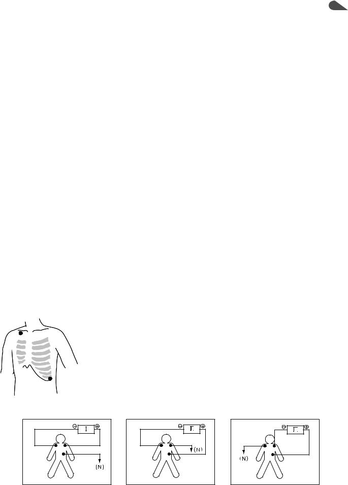
|
1. ECG MONITORING |
|
|
|
|
Preparing for ECG Monitoring |
|
1 |
|
|
|
|
|
|
Preparation Flowchart
1.Select the electrode lead and electrodes.
2.Connect the electrode lead to the ECG connection cord and connect the ECG connection cord to the ECG/RESP socket on the input unit.
3.Attach the disposable electrodes to the patient and attach the electrode lead to the electrodes.
4.Monitoring starts. Set necessary settings.
Number of Electrodes and Measuring Leads
The leads which can be monitored differ according to the type of electrode lead and number of electrodes used. This monitor automatically identifies the number of electrodes attached to the patient.
No. of Electrodes |
Lead |
Features |
|
|
|
3 |
I, II, III |
Can measure at the thoracic wall. |
|
|
|
6 |
I, II, III, aVR, aVL, aVF, two leads from V1 to V6 |
Similar to the standard 12 lead. |
|
|
|
10 |
I, II, III, aVR, aVL, aVF, V1 to V6 |
Standard 12 lead. |
|
|
|
Electrode Position
R/RA
 L/LA
L/LA
F/LL
3 Electrode Leads
Electrode Position
Symbol |
Lead Color (Clip Color) |
Electrode Position |
|
|
|
|
|
R |
Red (Red-beige) |
Right infraclavicular fossa |
|
RA |
White (White-beige) |
||
|
|||
L |
Yellow (Yellow-beige) |
Left infraclavicular fossa |
|
LA |
Black (Black-beige) |
||
|
|||
F |
Green (Green-beige) |
Lowest rib on the left anterior |
|
LL |
Red (Red-beige) |
axillary line |
Lead Connection
Lead I
R/RA |
L/LA |
|
F/LL |
Lead II |
Lead III |
R/RA |
L/LA |
R/RA |
L/LA |
|
F/LL |
|
F/LL |
User’s Guide Part II BSM-6000 |
1.5 |

1. ECG MONITORING
R/RA
 L/LA
L/LA
 Ca/Va Cb/Vb
N (RF/RL) F/LL
6 Electrode Leads
Electrode Position
The 5-electrode method with lead II and lead V5 is effective for monitoring myocardial ischemia. You can improve monitoring accuracy considerably by adding lead V4 to this combination. Ca and Cb (Va and Vb) can be at any
position of the standard 12 leads C1 to C6 (V1 to V6), but C4 and C5 (V4 and V5) are most appropriate for myocardial ischemic monitoring.
Symbol |
Lead Color (Clip Color) |
Electrode Position |
|
|
|
|
|
R |
Red (Red-beige) |
Right infraclavicular fossa |
|
RA |
White (White-beige) |
||
|
|||
L |
Yellow (Yellow-beige) |
Left infraclavicular fossa |
|
LA |
Black (Black-beige) |
||
|
|||
F |
Green (Green-beige) |
Lowest rib on the left anterior |
|
LL |
Red (Red-beige) |
axillary line |
|
N (RF) |
Black (Black-beige) |
Right anterior axillary line at the |
|
N (RL) |
Green (Green-beige) |
same level as F. |
|
Ca |
White (Brown-white) |
Fifth intercostal space on the left |
|
midclavicular line. (C4 position of |
|||
Va |
Brown (Blue-brown) |
||
standard 12 leads) |
|||
|
|
||
Cb |
White (Black-white) |
Left anterior axillary line at the same |
|
level as Ca. (C5 position of standard |
|||
Vb |
Brown (Orange-brown) |
||
12 leads) |
|||
|
|
||
Lead Position |
|
||
Standard limb leads
Lead I
R/RA L/LA
F/LL
N (RF/RL)
Lead II
R/RA L/LA
F/LL
N (RF/RL)
Lead III
R/RA |
L/LA |
|
F/LL |
N (RF/RL) |
|
Monopolar limb leads aVR lead
R/RA L/LA
F/LL
N (RF/RL)
aVL lead
R/RA |
L/LA |
|
F/LL |
N (RF/RL) |
|
aVF lead
R/RA |
L/LA |
F/LL |
N (RF/RL) |
Monopolar chest leads
V1 to V6 leads
 to
to

R/RA L/LA
F/LL
N (RF/RL)
1.6 |
User’s Guide Part II BSM-6000 |
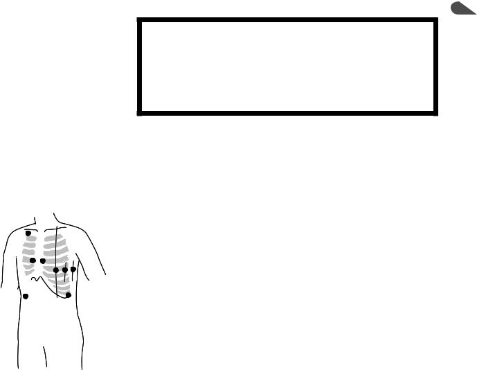
R/RA
 L/LA
L/LA
C1/V1 C2/V2
C6/V6
C3/V3 C4/V4
C4/V4
C5/V5
N (RF/RL) F/LL
1. ECG MONITORING
Mason-Likar Modification |
1 |
WARNING
Do not use 12 lead ECG interpretation results and measured values from the Mason-Likar modification for diagnosis because the limb electrode placement is not the same as the standard 12 lead ECG. This may cause wrong diagnosis since 12 lead ECG interpretation of this monitor is based on the standard 12 lead ECG.
The Mason-Likar modification places the four limb electrodes close to the shoulders and lower abdomen. The six C (V) electrodes are placed on the chest in the same position as the standard 12 lead ECG electrode placement. The waveforms acquired from the Mason-Likar modification are different from those of the standard 12 lead.
Electrode Position
Symbol |
Lead Color (Clip Color) |
Electrode Position |
|
|
|
|
|
R |
Red (Red-beige) |
Right infraclavicular fossa |
|
RA |
White (White-beige) |
||
|
|||
L |
Yellow (Yellow-beige) |
Left infraclavicular fossa |
|
LA |
Black (Black-beige) |
||
|
|||
F |
Green (Green-beige) |
Lowest rib on the left anterior |
|
LL |
Red (Red-beige) |
axillary line |
|
N (RF) |
Black (Black-beige) |
Right anterior axillary line at the |
|
N (RL) |
Green (Green-beige) |
same level as F. |
|
C1 |
White (Red-white) |
Fourth intercostal space at the right |
|
V1 |
Brown (Red-brown) |
border of the sternum. |
|
C2 |
White (Yellow-white) |
Fourth intercostal space at the left |
|
V2 |
Brown (Yellow-brown) |
border of the sternum. |
|
C3 |
White (Green-white) |
Halfway between C2 and C4. |
|
V3 |
Brown (Green-brown) |
||
|
|||
C4 |
White (Brown-white) |
Fifth intercostal space on the left |
|
V4 |
Brown (Blue-brown) |
midclavicular line. |
|
C5 |
White (Black-white) |
Left anterior axillary line at the same |
|
V5 |
Brown (Orange-brown) |
level as C4. |
|
C6 |
White (Purple-white) |
Left midaxillary line at the same |
|
V6 |
Brown (Purple-brown) |
level as C4. |
Lead Connection
The lead connection is the same as the 6 electrode lead.
User’s Guide Part II BSM-6000 |
1.7 |
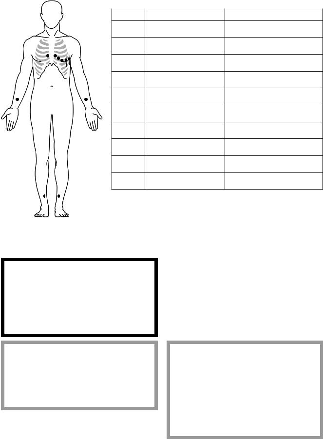
1. ECG MONITORING |
|
|
|
|
|
|
|
|
Standard 12 Leads |
|
|
|
|
|
Electrode Position |
|
|
|
|
|
Symbol |
Lead Color (Clip Color) |
Electrode Position |
|
|
|
R |
Red (Red-beige) |
Inside of right arm between the wrist |
|
|
|
RA |
White (White-beige) |
and the elbow |
|
|
|
L |
Yellow (Yellow-beige) |
Inside of left arm between the wrist |
C2/V2 |
C6/V6 |
|
LA |
Black (Black-beige) |
and the elbow |
C1/V1 |
|
|
F |
Green (Green-beige) |
Inside of the right calf between the |
C3/V3 |
|
|
|||
C4/V4 |
|
|
LL |
Red (Red-beige) |
knee and the ankle |
C5/V5 |
|
||||
|
|
|
N (RF) |
Black (Black-beige) |
Inside of the left calf between the |
|
|
|
N (RL) |
Green (Green-beige) |
knee and the ankle |
R/RA |
|
L/LA |
C1 |
White (Red-white) |
Fourth intercostal space at the right |
|
V1 |
Brown (Red-brown) |
border of the sternum. |
||
|
|
|
|||
|
|
|
C2 |
White (Yellow-white) |
Fourth intercostal space at the left |
|
|
|
V2 |
Brown (Yellow-brown) |
border of the sternum. |
|
|
|
C3 |
White (Green-white) |
Halfway between C2 and C4. |
|
|
|
V3 |
Brown (Green-brown) |
|
|
|
|
|
||
|
|
|
C4 |
White (Brown-white) |
Fifth intercostal space on the left |
|
|
|
V4 |
Brown (Blue-brown) |
midclavicular line. |
|
|
|
C5 |
White (Black-white) |
Left anterior axillary line at the same |
|
|
|
V5 |
Brown (Orange-brown) |
level as C4. |
|
|
|
C6 |
White (Purple-white) |
Left midaxillary line at the same |
|
|
|
V6 |
Brown (Purple-brown) |
level as C4. |
N (RF/RL) |
F/LL |
|
Lead Connection |
|
|
|
|
|
|
||
The lead connection is the same as the 6 electrode lead.
Selecting Electrodes and Lead
Select the appropriate electrodes and lead according to the purpose.
WARNING
When using a defibrillator together with the monitor, use Ag/AgCl electrodes. Other types of electrodes, stainless steel in particular, will adversely affect the ECG waveform by slowing the baseline recovery on the monitor and result in no monitoring immediately following defibrillation.
CAUTION
Only use Nihon Kohden specified electrodes and electrode leads. When other type of electrodes or electrode leads are used, the “CHECK ELECTRODES” message may be displayed and ECG monitoring may stop.
CAUTION
•When using the electrodes with DIN type lead, use only Vitrode V or N electrodes. If other electrodes are used, the electrode lead might not be properly connected and ECG monitoring may be unstable.
•Do not use electrodes of different metals. ECG monitoring may be unstable if electrodes of different metals are used.
NOTE
|
Electrode leads other than Nihon Kohden’s might not be defibrillator- |
1.8 |
proof. |
User’s Guide Part II BSM-6000 |
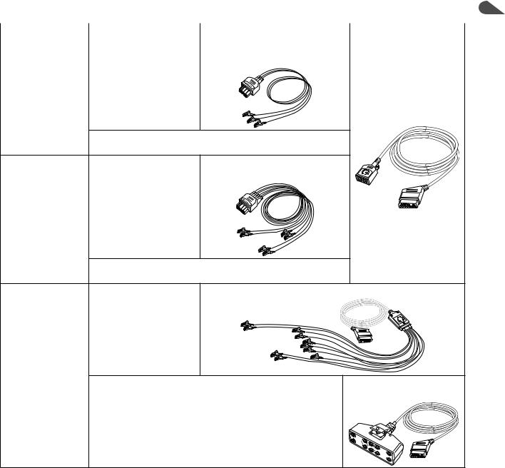
|
|
1. ECG MONITORING |
|
Types of Electrodes and Lead |
1 |
||
|
|
|
|
No. of Electrodes Disposable Electrodes |
Electrode Lead |
ECG Connection Cord |
|
|
|
|
|
Vitrode L-150, L-150X, |
BR-903P (IEC)/BR-903PA (AHA) |
JC-906P (IEC)/JC-906PA |
|
F-150M, F-150S |
(Clip type, 0.8 m) |
(AHA), 3 m |
|
3
(I, II, III)
Disposable Electrode with DIN type lead, Vitrode V-090M3, V- 09IO3, V-120S3, N-03IS3
Vitrode L-150, L-150X, |
BR-906P (IEC)/BR-906PA (AHA) |
F-150M, F-150S |
(Clip type, 0.8 m) |
6
(I, II, III, aVR, aVL, aVF, 2 from V1 to V6)
Disposable Electrode with DIN type lead, Vitrode V-060M6, V- 06IO6
|
Vitrode L-150, L-150X, |
ECG Patient Cable BJ-900P (IEC)/BJ-900PA (AHA) |
|
|
F-150M, F-150S |
|
|
10 |
|
|
|
(I, II, III, aVR, aVL, |
|
|
|
aVF, V1, V2, V3, V4, Disposable Electrode with DIN type lead, Vitrode V-040M4, V- |
JC-900P (IEC)/ |
||
V5, V6) |
04IO4, V-060M6, V-06IO6 |
|
JC-900PA (AHA) |
User’s Guide Part II BSM-6000 |
1.9 |
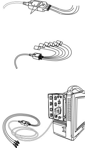
1. ECG MONITORING
Connecting Cables and Attaching Disposable Electrodes
Connecting the Electrode Cable to the Input Unit
1.Connect the electrode lead and ECG connection cord so that their white panels face the same side.
White panels 
When using the electrode with DIN type lead, connect the electrode lead of the electrode directly to the ECG connection cord according to the panel symbols.
2.Connect the ECG connection cord to the ECG/RESP socket on the input unit.
When connecting the 3-electrode lead
When using more than 3 electrodes with DIN type lead with JC-906P or JC906PA ECG connection cord, the number of electrodes must be set on the OTHER page of the ECG window. Refer to the “Changing the Number of Electrodes” section.
1.10 |
User’s Guide Part II BSM-6000 |

|
|
|
|
|
1. ECG MONITORING |
|
||
|
Attaching Disposable Electrodes to the Patient |
1 |
||||||
|
Attach the electrodes to the patient by referring to the manual provided with the |
|
||||||
|
electrodes. |
|
|
|
|
|
|
|
|
|
|
|
|
|
|
|
|
|
|
|
|
|
|
|
|
|
|
WARNING |
|
|
|
CAUTION |
|
|
|
|
After attaching the electrode to the patient and |
|
|
|
Do not reuse disposable electrodes. |
|
|
|
|
connecting the cable to the monitor, check that |
|
|
|
|
|
|
|
|
|
|
|
|
|
|
|
|
|
|
|
|
|
|
|
||
|
electrodes are attached to the patient and check |
|
|
|
|
|
|
|
|
that the cable is connected to the monitor |
|
|
|
|
|
|
|
|
properly. When the electrodes are removed from |
|
|
|
|
|
|
|
|
the patient, do not touch the metal part of the |
|
|
|
|
|
|
|
|
electrode with bare hands or let the metal part of |
|
|
|
|
|
|
|
|
the electrode contact the metal part of the bed or |
|
|
|
|
|
|
|
|
any other conductive parts. Failure to follow this |
|
|
|
|
|
|
|
|
warning may cause electrical shock or injury to |
|
|
|
|
|
|
|
|
the patient by discharged energy. |
|
|
|
|
|
|
|
|
|
|
|
|
|
|
|
|
|
|
|
|
|
|
|
|
|
NOTE
•To maintain good contact between the electrode and skin, check that the paste of the disposable electrode is not dry.
•When contact of the disposable electrode becomes poor, replace the electrode with a new one immediately. Otherwise, contact impedance between the skin and electrode increases and the correct ECG cannot be obtained.
To obtain a stable ECG:
•Shave excess hair.
•Rub the patient’s skin with a piece of cotton where the electrodes are to be attached.
•If the skin is dirty, clean with soap and water. Dry completely.
•Clean the patient’s skin with a piece of cotton moistened with alcohol. Dry completely.
User’s Guide Part II BSM-6000 |
1.11 |

1. ECG MONITORING
Monitoring ECG
When electrodes are attached to the patient and cables are connected properly, ECG and heart rate appear on the screen. The monitor automatically learns the patient’s dominant ECG.
One lead appears on the home screen. Up to three leads can be displayed on the home screen when monitoring with six or ten leads. You can display eight leads on the 12 LEAD window when monitoring with six electrodes and twelve leads when monitoring with ten electrodes. To perform 12 lead ECG interpretation, ECG must be monitored with ten electrodes. For details about the 12 lead ECG interpretation, refer to Operator’s Manual or Section 7 of the User’s Guide Part I.
The number of traces to be displayed on the home screen can be set on the
DISPLAY window. Refer to “Changing Settings for Home Screen” in Operator’s
Manual or Section 4 of the User’s Guide Part I.
CAUTION
When the “CHECK ELECTRODE” message is displayed, ECG is not monitored properly and the ECG alarm does not function. Check the electrode, electrode leads and connection cord, and if necessary, replace with new ones.
CAUTION
When the “NOISE” or “CANNOT ANALYZE” message is displayed, ECG data and alarm are not reliable. Remove the cause by checking the electrodes, electrode leads, patient’s body movement, EMG and peripheral instruments grounding. Also make sure that an electric blanket is not used.
NOTE
•After adjusting the sensitivity of the ECG on the screen and changing necessary settings, check that the dominant QRS is appropriate.
•The maximum heart rate range is 300 beats/min. “300” is displayed on the screen even when the patient’s heart rate is above 300.
1.12 |
User’s Guide Part II BSM-6000 |
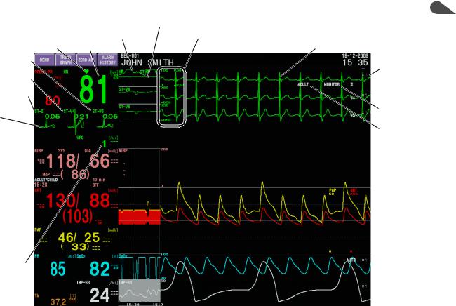
1. ECG MONITORING
ECG Information on the Home Screen |
1 |
Heart rate trendgraph
QRS sync mark Heart rate
ST level of the third trace
ST level of the
second trace ST level of the
first trace
The ST recall waveform, and reference ST recall waveform of selected monitoring ECG leads are displayed on the home screen depending on the settings on the
ST window of the REVIEW window. Up to 3 waveforms can be displayed. Refer to Section 6 of the User’s Guide Part I.
VPC
ST level trendgraph
Scale of heart rate and ST level trendgraphs
ECG waveform
Sensitivity
 Lead
Lead
Filter setting QRS detection type
ECG Data Display
The following ECG related data is acquired when ECG is monitored.
|
|
|
Displayed Data |
|
|
|
Screen/Window |
<ARRHYTHMIA ANALYSIS> is |
<ARRHYTHMIA ANALYSIS> is |
|
|
|
set to ON*1 |
set to OFF*1 |
|
|
|
Heart rate |
Heart rate |
|
|
|
ST level |
ST level |
|
Home screen |
Arrhythmia classification message |
“ASYSTOLE” alarm occurrence |
|
|
Number of VPC per minute |
|
||
|
|
|
|
|
|
|
|
Arrhythmia alarm occurrence (when |
|
|
|
|
arrhythmia alarm is set to ON*2) |
|
|
|
|
Heart rate trendgraph |
Heart rate trendgraph |
|
TREND window |
ST level trendgraph |
ST level trendgraph |
|
|
Number of VPC trendgraph |
Heart rate list |
||
|
(Refer to Operator’s Manual or |
|||
|
Heart rate list |
ST level list |
||
|
Section 6 of the User’s Guide Part I) |
|||
|
ST level list |
|
||
|
|
|
Number of VPC list |
|
|
ARRHYTHMIA RECALL window |
Recall files of the arrhythmias set to |
“ASYSTOLE” recall files |
|
|
(Refer to Operator’s Manual or |
be saved*3 |
|
|
|
Section 6 of the User’s Guide Part I) |
|
|
|
|
ST RECALL window |
ST recall files |
ST recall files |
|
|
(Refer to Operator’s Manual or |
|
|
|
|
Section 6 of the User’s Guide Part I) |
|
|
|
*1 |
Arrhythmia analysis can be turned on or off on the ECG window → ARRHYTH ANALYSIS page. |
|||
*2 |
Alarm on/off and threshold can be set individually for certain arrhythmias on the ARRHYTH page on the ECG |
|||
|
|
window or ARRHYTH ALARMS window. |
|
|
|
|
When alarm recording is turned on, the data and waveform are recorded at the arrhythmia alarm occurrence. |
||
*3 |
The arrhythmia waveforms to be saved as recall files are set on the RECALL window of the Review window. |
|||
User’s Guide Part II BSM-6000 |
|
1.13 |
||
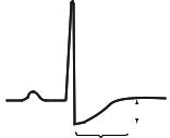
1. ECG MONITORING
Measuring ST Level
The ST level is the amplitude between the baseline and ST wave. The ECG waveform is averaged for 15 seconds to remove artifacts. The baseline and the ST wave are detected from the averaged ECG, and the ST level is measured.
Baseline |
|
|
NOTE |
||
|
|
• If there are too many arrhythmias, there is noise on the ECG, or the |
|||
|
|
|
|
|
|
|
|
|
ST level |
||
|
|
|
heart rate is below 32, ST level might not be measured and ST level is |
||
|
|
|
|
|
|
|
|
ST wave |
|
|
|
|
|
|
|
not displayed on the screen. |
|
•Although the ST algorithm has been tested for accuracy of the ST analysis result, the significance of the ST level changes need to be determined only by a physician.
ST levels of up to 12 leads can be displayed on the ST window of the Review window. Refer to “ST Recall Window” in Operator’s Manual or Section 6 of the User’s Guide Part I.
You can change the ISO point, J point and ST point for ST level measurement on the ECG window → ST POINT page. Refer to the “Changing the ST Level
Measurement Condition” section.
1.14 |
User’s Guide Part II BSM-6000 |

|
1. ECG MONITORING |
|
|
|
|
Monitoring Arrhythmia |
|
1 |
|
|
|
|
|
|
General
The following functions are available for arrhythmia monitoring.
•Arrhythmia alarm indication (alarm sound, screen message and alarm indicator lamp). Refer to Operator’s Manual or Section 5 of the User’s Guide Part I.
•Arrhythmia waveform storage (Arrhythmia recall files). Refer to Operator’s
Manual or Section 6 of the User’s Guide Part I.
•Arrhythmia waveform recording. Refer to Operator’s Manual or Section 10 of the User’s Guide Part I.
•VPC display and trendgraph. Refer to Operator’s Manual or Section 4 and 6 of the User’s Guide Part I.
WARNING
For arrhythmia monitoring, set <ARRHYTHMIA ANALYSIS> on the ECG window to ON. Otherwise, there is no sound or indication for arrhythmia alarms (except for ASYSTOLE).
When arrhythmia analysis is set to on, arrhythmia analysis starts as soon as the ECG monitoring starts. The monitor automatically detects and classifies arrhythmia by comparing each beat of the real-time ECG waveform to a
reference ECG waveform (dominant QRS). If the following points of a QRS do not match the dominant QRS, that QRS is recognized as an arrhythmia.
•RR interval
•QRS width
•QRS amplitude
•QRS polarity
It is important to check the dominant QRS on the ECG window at the start of
ECG monitoring for accurate arrhythmia monitoring.
CAUTION
At the start of ECG monitoring, check that the dominant QRS is appropriate. Otherwise arrhythmia monitoring may be inaccurate.
When the QRS wave or RR interval changes too frequently, it becomes difficult for the monitor to distinguish between the normal ECG and arrhythmia. To solve this problem, the monitor uses pattern matching and multi template matching for analyzing arrhythmia. However, when the patient’s QRS changes rapidly, check that the appropriate dominant QRS is used for arrhythmia analysis.
User’s Guide Part II BSM-6000 |
1.15 |
Loading...