


Nihon Kohden Lifescope H OPV User manual
SERVICE MANUAL
OPV-1500K
Life Scope N
BEDSIDE MONITOR
OPV-1500
0634-001869B
OPV-1500K
Life Scope N
BEDSIDE MONITOR
OPV-1500
0634-001869B

line cutting
Model: OPV-1500K
Manual code no.: 0634-001869B
Reader Comment Card
We welcome your comments about this manual. Your comments and suggestions help us improve our manuals. Please circle the number for each of the following statements corresponding to your evaluation and add comments in the space provided.
Fax or send your completed comment card to:
Fax: +81 (3) 5996-8100
International Div., Sales Promotion Section, Nihon Kohden Corp., 1-31-4, Nishiochiai Shinjuku-ku, Tokyo 161-8560, Japan
|
Strongly |
Agree |
Neutral |
Disagree |
Strongly |
|
Agree |
|
|
|
Disagree |
This manual is organized. |
1 |
2 |
3 |
4 |
5 |
I can find the information I want. |
1 |
2 |
3 |
4 |
5 |
The information is accurate. |
1 |
2 |
3 |
4 |
5 |
I can understand the instructions. |
1 |
2 |
3 |
4 |
5 |
The illustrations are appropriate and helpful. |
1 |
2 |
3 |
4 |
5 |
The manual length is appropriate. |
1 |
2 |
3 |
4 |
5 |
Comments:
Thank you for your cooperation. We appreciate it very much.
Name:
Occupation/Position:
Hospital/Company:
Address:
Phone:
|
|
CONTENTS |
|
Contents |
|
|
GENERAL HANDLING PRECAUTIONS ....................................................................... |
i |
|
WARRANTY POLICY ................................................................................................... |
ii |
|
EMC RELATED CAUTION .......................................................................................... |
iii |
|
Conventions Used in this Manual and Instrument ...................................................... |
v |
|
Warnings, Cautions and Notes ......................................................................... |
v |
|
Explanations of the Symbols in this Manual and Instrument ........................... |
vi |
|
On panels .......................................................................................................... |
vi |
|
On screen......................................................................................................... |
vii |
|
Others............................................................................................................... |
vii |
Section 1 |
General.................................................................................... |
1C.1 |
|
Introduction ......................................................................................................................... |
1.1 |
|
General Information on Serving ......................................................................................... |
1.2 |
|
Service Policy, Service Parts and Patient Safety Checks ................................................ |
1.4 |
|
Service Policy .......................................................................................................... |
1.4 |
|
Service Parts ........................................................................................................... |
1.4 |
|
Patient Safety Checks .............................................................................................. |
1.5 |
|
Maintenance Equipments and Tools ......................................................................... |
1.5 |
|
General Safety Information ................................................................................................. |
1.6 |
|
General ..................................................................................................................... |
1.6 |
|
Installation ................................................................................................................ |
1.7 |
|
Using KC-012P Cart ................................................................................................. |
1.8 |
|
Using ZB-900PK Transmitter .................................................................................... |
1.8 |
|
Using YL-001P Alarm Pole ....................................................................................... |
1.8 |
|
Battery ...................................................................................................................... |
1.9 |
|
ECG Monitoring ....................................................................................................... |
1.10 |
|
Respiration Monitoring ............................................................................................ |
1.11 |
|
SpO2 Monitoring ...................................................................................................... |
1.12 |
|
NIBP Monitoring ...................................................................................................... |
1.14 |
|
Maintenance ............................................................................................................ |
1.15 |
|
Specifications .................................................................................................................... |
1.16 |
|
Panel Description .............................................................................................................. |
1.20 |
|
Front Panel .............................................................................................................. |
1.20 |
|
Power Panel ............................................................................................................. |
1.20 |
|
Socket Panel ........................................................................................................... |
1.21 |
|
Right Side Panel ...................................................................................................... |
1.21 |
|
Rear Panel ............................................................................................................... |
1.22 |
|
Board/Unit Location View .................................................................................................. |
1.23 |
|
Composition ....................................................................................................................... |
1.24 |
|
Standard Components ............................................................................................. |
1.24 |
|
Options .................................................................................................................... |
1.24 |
|
Cable Connections ............................................................................................................ |
1.25 |
Service Manual OPV-1500K |
C.1 |
CONTENTS
Section 2 |
Troubleshooting ..................................................................... |
2C.1 |
|
General ............................................................................................................................... |
2.1 |
|
Instrument Problems .......................................................................................................... |
2.2 |
|
Vital Sign Problems ............................................................................................................ |
2.4 |
|
ECG .......................................................................................................................... |
2.4 |
|
Respiration ............................................................................................................... |
2.6 |
|
SpO2 ...................................................................................................................................................................................................................... |
2.7 |
|
NIBP ......................................................................................................................... |
2.9 |
Section 3 |
Diagnostic Check ................................................................... |
3C.1 |
|
Introduction ......................................................................................................................... |
3.1 |
|
Calling Up the MAINTENANCE MODE Screen ................................................................. |
3.1 |
|
Display Check .................................................................................................................... |
3.2 |
|
Sound Check ...................................................................................................................... |
3.3 |
|
Memory Check ................................................................................................................... |
3.4 |
|
Key Check .......................................................................................................................... |
3.5 |
|
Optional Transmitter Check ................................................................................................ |
3.6 |
|
Optional Recorder Check ................................................................................................... |
3.7 |
|
NIBP Check ........................................................................................................................ |
3.8 |
|
Examination .............................................................................................................. |
3.8 |
|
Safety Device Test .................................................................................................... |
3.9 |
|
Inflation Test ............................................................................................................ |
3.10 |
|
Deflation Test (Quick deflation test) ........................................................................ |
3.11 |
|
Step Deflation Test .................................................................................................. |
3.12 |
|
Air Leak Test ............................................................................................................ |
3.14 |
|
ECG and Impedance Method Respiration Checks ........................................................... |
3.15 |
|
SpO2 Check ....................................................................................................................... |
3.16 |
Section 4 |
Board/Unit Description .......................................................... |
4C.1 |
|
Block Diagram .................................................................................................................... |
4.1 |
|
Input Board ......................................................................................................................... |
4.2 |
|
NIBP Block ............................................................................................................... |
4.2 |
|
SpO2 Block .............................................................................................................. |
4.2 |
|
ECG Block ................................................................................................................ |
4.2 |
|
RESP Block .............................................................................................................. |
4.2 |
|
Control Block ............................................................................................................ |
4.2 |
|
Isolated Power Supply Block.................................................................................... |
4.2 |
|
POWER Board .................................................................................................................... |
4.3 |
|
USER IF Board ................................................................................................................... |
4.3 |
|
PRINTER CN Board ........................................................................................................... |
4.3 |
C.2 |
Service Manual OPV-1500K |
|
CONTENTS |
|
|
CONTROL Board ................................................................................................................ |
4.3 |
|
Power Supply Unit .............................................................................................................. |
4.3 |
Section 5 |
Disassembly and Assembly .................................................. |
5C.1 |
|
Opening the Instrument ...................................................................................................... |
5.1 |
|
Removing the Rear Enclosure ................................................................................. |
5.1 |
|
Separating the Front Enclosure and Chassis Block ................................................ |
5.1 |
|
Removing the LCD Unit ........................................................................................... |
5.2 |
|
Removing the USER IF Board ................................................................................. |
5.2 |
|
Removing the INPUT Board ..................................................................................... |
5.3 |
|
Removing the NIBP Pump ....................................................................................... |
5.4 |
|
Removing the POWER Board, CONTROL Board and PRINTER CN Board ........... |
5.4 |
|
Removing the Recorder Unit (Option) ..................................................................... |
5.5 |
|
Removing the POWER Board .................................................................................. |
5.5 |
|
Removing the CONTROL Board .............................................................................. |
5.5 |
|
Removing the PRINTER CN Board .......................................................................... |
5.6 |
|
Removing the Power Supply Unit ............................................................................. |
5.6 |
|
Replacing the Lithium Battery ............................................................................................ |
5.7 |
|
Installing the Optional RG-101W Recorder Unit ................................................................ |
5.8 |
Section 6 |
Maintenance ........................................................................... |
6C.1 |
|
To Be Replaced Periodically ............................................................................................... |
6.1 |
|
Required Tools .................................................................................................................... |
6.1 |
|
Measuring and Test Equipment .......................................................................................... |
6.2 |
|
Maintenance Check Items and Schedule ........................................................................... |
6.3 |
|
External .................................................................................................................... |
6.3 |
|
Input Conditions ....................................................................................................... |
6.3 |
|
Power ........................................................................................................................ |
6.4 |
|
Operations ................................................................................................................ |
6.4 |
|
Display ...................................................................................................................... |
6.4 |
|
Sound........................................................................................................................ |
6.4 |
|
ECG .......................................................................................................................... |
6.4 |
|
RESP ........................................................................................................................ |
6.5 |
|
NIBP ......................................................................................................................... |
6.5 |
|
SpO2 ...................................................................................................................................................................................................................... |
6.5 |
|
Alarm ........................................................................................................................ |
6.6 |
|
Clock ........................................................................................................................ |
6.6 |
|
Optional Recorder Built in the Instrument ................................................................ |
6.6 |
|
Optional Transmitter Attached to the Instrument ..................................................... |
6.6 |
|
Safety........................................................................................................................ |
6.7 |
|
Installation Condition ................................................................................................ |
6.7 |
Service Manual OPV-1500K |
C.3 |
CONTENTS
Section 7 |
Replaceable Parts List ........................................................... |
7C.1 |
|
Replaceable Parts List ....................................................................................................... |
7.2 |
Section 8 |
Connector Pin Assignment .................................................... |
8C.1 |
|
INPUT Board ...................................................................................................................... |
8.1 |
|
CN101 ECG/RESP Socket....................................................................................... |
8.1 |
|
CN401 (for quick deflation valve, valve1) ................................................................ |
8.1 |
|
CN402 (for slow deflation valve, valve2) ................................................................. |
8.1 |
|
CN403 (not used) ..................................................................................................... |
8.1 |
|
CN701 SpO2 Socket ................................................................................................. |
8.2 |
|
CN902 (not used) ..................................................................................................... |
8.2 |
|
CN1001 (for POWER board) .................................................................................... |
8.2 |
|
Power Board ....................................................................................................................... |
8.3 |
|
CN1 (for power supply unit) ..................................................................................... |
8.3 |
|
CN2 (for rechargeable battery) ................................................................................ |
8.3 |
|
CN3 (for INPUT board)............................................................................................. |
8.3 |
|
CN4 (for NIBP pump) ............................................................................................... |
8.3 |
|
CN5 (for CONTROL board) ...................................................................................... |
8.4 |
|
USER IF Board ................................................................................................................... |
8.5 |
|
CN101 (for CONTROL board) .................................................................................. |
8.5 |
|
PRINTER CN Board ........................................................................................................... |
8.5 |
|
CN101 (for CONTROL board) .................................................................................. |
8.5 |
|
CN102 (for recorder unit) ......................................................................................... |
8.6 |
|
CN103 (for recorder unit) ......................................................................................... |
8.6 |
|
CONTROL Board ................................................................................................................ |
8.7 |
|
CN1 Alarm pole socket ............................................................................................ |
8.7 |
|
CN2 (for LCD unit) .................................................................................................... |
8.7 |
|
CN3 (for POWER board) .......................................................................................... |
8.8 |
|
CN4 (for PRINTER CN board) ................................................................................. |
8.9 |
|
CN5 ZB socket ......................................................................................................... |
8.9 |
|
CN6 (for USER IF board) ........................................................................................ |
8.10 |
|
CN7 (not used) ........................................................................................................ |
8.10 |
|
CN8 (not used) ........................................................................................................ |
8.10 |
|
CN9 (for speaker) .................................................................................................... |
8.10 |
C.4 |
Service Manual OPV-1500K |
GENERAL HANDLING PRECAUTIONS
This device is intended for use only by qualified medical personnel.
Use only Nihon Kohden approved products with this device. Use of non-approved products or in a non-approved manner may affect the performance specifications of the device. This includes, but is not limited to, batteries, recording paper, pens, extension cables, electrode leads, input boxes and AC power.
Please read these precautions thoroughly before attempting to operate the instrument.
1.To safely and effectively use the instrument, its operation must be fully understood.
2.When installing or storing the instrument, take the following precautions:
(1)Avoid moisture or contact with water, extreme atmospheric pressure, excessive humidity and temperatures, poorly ventilated areas, and dust, saline or sulphuric air.
(2)Place the instrument on an even, level floor. Avoid vibration and mechanical shock, even during transport.
(3)Avoid placing in an area where chemicals are stored or where there is danger of gas leakage.
(4)The power line source to be applied to the instrument must correspond in frequency and voltage to product specifications, and have sufficient current capacity.
(5)Choose a room where a proper grounding facility is available.
3.Before Operation
(1)Check that the instrument is in perfect operating order.
(2)Check that the instrument is grounded properly.
(3)Check that all cords are connected properly.
(4)Pay extra attention when the instrument is combined with other instruments to avoid misdiagnosis or other problems.
(5)All circuitry used for direct patient connection must be doubly checked.
(6)Check that battery level is acceptable and battery condition is good when using battery-operated models.
4.During Operation
(1)Both the instrument and the patient must receive continual, careful attention.
(2)Turn power off or remove electrodes and/or transducers when necessary to assure the patient’s safety.
(3)Avoid direct contact between the instrument housing and the patient.
5.To Shutdown After Use
(1)Turn power off with all controls returned to their original positions.
(2)Remove the cords gently; do not use force to remove them.
(3)Clean the instrument together with all accessories for their next use.
6.The instrument must receive expert, professional attention for maintenance and repairs. When the instrument is not functioning properly, it should be clearly marked to avoid operation while it is out of order.
7.The instrument must not be altered or modified in any way.
8.Maintenance and Inspection:
(1)The instrument and parts must undergo regular maintenance inspection at least every 6 months.
(2)If stored for extended periods without being used, make sure prior to operation that the instrument is in perfect operating condition.
Service Manual OPV-1500K |
i |
(3)Technical information such as parts list, descriptions, calibration instructions or other information is available for qualified user technical personnel upon request from your Nihon Kohden distributor.
9.When the instrument is used with an electrosurgical instrument, pay careful attention to the application and/or location of electrodes and/or transducers to avoid possible burn to the patient.
10.When the instrument is used with a defibrillator, make sure that the instrument is protected against defibrillator discharge. If not, remove patient cables and/or transducers from the instrument to avoid possible damage.
WARRANTY POLICY
Nihon Kohden Corporation (NKC) shall warrant its products against all defects in materials and workmanship for one year from the date of delivery. However, consumable materials such as recording paper, ink, stylus and battery are excluded from the warranty.
NKC or its authorized agents will repair or replace any products which prove to be defective during the warranty period, provided these products are used as prescribed by the operating instructions given in the operator’s and service manuals.
No other party is authorized to make any warranty or assume liability for NKC’s products. NKC will not recognize any other warranty, either implied or in writing. In addition, service, technical modification or any other product change performed by someone other than NKC or its authorized agents without prior consent of NKC may be cause for voiding this warranty.
Defective products or parts must be returned to NKC or its authorized agents, along with an explanation of the failure. Shipping costs must be pre-paid.
This warranty does not apply to products that have been modified, disassembled, reinstalled or repaired without Nihon Kohden approval or which have been subjected to neglect or accident, damage due to accident, fire, lightning, vandalism, water or other casualty, improper installation or application, or on which the original identification marks have been removed.
In the USA and Canada other warranty policies may apply.
ii |
Service Manual OPV-1500K |

EMC RELATED CAUTION
This equipment and/or system complies with the International Standard IEC60601-1-2 for electromagnetic compatibility for medical electrical equipment and/or system. However, an electromagnetic environment that exceeds the limits or levels stipulated in the IEC60601-1-2, can cause harmful interference to the equipment and/or system or cause the equipment and/or system to fail to perform its intended function or degrade its intended performance. Therefore, during the operation of the equipment and/or system, if there is any undesired deviation from its intended operational performance, you must avoid, identify and resolve the adverse electromagnetic effect before continuing to use the equipment and/or system.
The following describes some common interference sources and remedial actions:
1.Strong electromagnetic interference from a nearby emitter source such as an authorized radio station or cellular phone:
Install the equipment and/or system at another location if it is interfered with by an emitter source such as an authorized radio station. Keep the emitter source such as cellular phone away from the equipment and/or system.
2.Radio-frequency interference from other equipment through the AC power supply of the equipment and/ or system:
Identify the cause of this interference and if possible remove this interference source. If this is not possible, use a different power supply.
3.Effect of direct or indirect electrostatic discharge:
Make sure all users and patients in contact with the equipment and/or system are free from direct or indirect electrostatic energy before using it.
4.Electromagnetic interference with any radio wave receiver such as radio or television:
If the equipment and/or system interferes with any radio wave receiver, locate the equipment and/or system as far as possible from the radio wave receiver.
If the above suggested remedial actions do not solve the problem, consult your Nihon Kohden Corporation
subsidiary or distributor for additional suggestions.
Service Manual OPV-1500K |
iii |
In IEC 60601-1-2 Medical Electronic Equipment, Part 1: General Requirements for Safety, 2. Collateral Standard: Electromagnetic compatibility-Requirements and test. Section 36. 202. 2 Radiated radiofrequency electromagnetic fields, PATIENT COUPLED EQUIPMENT and/or SYSTEMS applicable IMMUNITY test methods are under consideration at SC62A/WG13. The 3 V/m IMMUNITY level may be inappropriate especially when measuring SpO2 because physiological signals can be much smaller than those induced by a 3 V/m electromagnetic field.
When measuring SpO2, various interference may produce false waveforms which look like pulse waveforms. SpO2 value and pulse rate may be measured from these false waveforms, causing the alarm to function improperly.
When installing the monitor, avoid locations where the monitor may receive strong electromagnetic interference such as radio or TV stations, cellular phone or mobile two-way radios.
WARNING
Interaction Between Minute Ventilation Rate-Adaptive Pacemakers and Cardiac Monitoring and Diagnostic Equipment*
The bioelectric impedance measurement sensor of a minute ventilation rate-adaptive implantable pacemaker may be affected by cardiac monitoring and diagnostic equipment which is connected to the same patient. If this occurs, the pacemaker may pace at its maximum rate and give incorrect data to the monitor or diagnostic equipment. If this occurs, disconnect the monitor or diagnostic equipment from the patient or change the setting on the pacemaker by referring to the pacemaker’s manual. For more details, contact your pacemaker distributor or Nihon Kohden distributor.
*Minute ventilation is sensed in rate-adaptive pacemakers by a technology known as bioelectric impedance measurement (BIM). Many medical devices in addition to pacemakers use this technology. When one of these devices is used on a patient with an active, minute ventilation rate-adaptive pacemaker, the pacemaker may erroneously interpret the mixture of BIM signals created in the patient, resulting in an elevated pacing rate.
For more information, see the FDA web site. http://www.fda.gov/cdrh/safety.html
iv |
Service Manual OPV-1500K |

Conventions Used in this Manual and Instrument
Warnings, Cautions and Notes
Warnings, cautions and notes are used in this manual to alert or signal the reader to specific information.
WARNING
A warning alerts the user to possible injury or death associated with the use or misuse of the instrument.
CAUTION
A caution alerts the user to possible injury or problems with the instrument associated with its use or misuse such as instrument malfunction, instrument failure, damage to the instrument, or damage to other property.
NOTE
A note provides specific information, in the form of recommendations, prerequirements, alternative methods or supplemental information.
Service Manual OPV-1500K |
v |
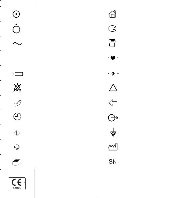
Explanations of the Symbols in this Manual and Instrument
The following symbols found in this manual/instrument bear the respective descriptions as given.
On panels
Symbol |
Description |
Symbol |
Description |
||||||||
|
|
|
|
|
|
|
|
|
|
|
|
|
|
|
|
Monitor power on |
|
|
|
|
|
|
Home (monitoring screen) |
|
|
|
|
|
|
|
|
|
|
|
|
|
|
|
|
Monitor power off |
|
|
|
|
|
|
Setting screen |
|
|
|
|
|
|
|
|
|
|
||
|
|
|
|
|
|
|
|
|
|
||
|
|
|
|
|
|
|
|
|
|
|
|
|
|
|
|
AC operation (front panel) |
|
|
|
|
|
|
Record start/stop (for optional |
|
|
|
|
Alternating current (rear panel) |
|
|
|
|
|
|
recorder unit) |
|
|
|
|
|
|
|
|
|
|
|
|
|
|
|
|
Battery operation |
|
|
|
|
|
|
Defibrillation-proof type CF applied |
|
|
|
|
|
|
|
|
|
|
||
|
|
|
|
|
|
|
|
|
|
part |
|
|
|
|
|
|
|
|
|
|
|
|
|
|
|
|
|
|
|
|
|
|
|
|
|
|
|
|
|
|
|
|
|
|
|
|
|
|
|
|
|
Battery charging |
|
|
|
|
|
|
Defibrillation-proof type BF applied |
|
|
|
|
|
|
|
|
|
|
||
|
|
|
|
|
|
|
|
|
|
part |
|
|
|
|
|
|
|
|
|
|
|
|
|
|
|
|
|
|
|
|
|
|
|
|
|
|
|
|
|
Alarm silence |
|
|
|
|
|
|
Attention, consult operator’s |
|
|
|
|
|
|
|
|
|
|
manual |
|
|
|
|
|
|
|
|
|
|
|
|
|
|
|
|
|
|
|
|
|
|
|
|
|
|
|
|
|
NIBP |
|
|
|
|
|
|
ZB-900PK transmitter socket |
|
|
|
|
|
|
|
|
|
|
|
|
|
|
|
|
NIBP interval |
|
|
|
|
|
|
Output terminal |
|
|
|
|
|
|
|
|
|
|
|
|
|
|
|
|
NIBP start |
|
|
|
|
|
|
Equipotential terminal |
|
|
|
|
|
|
|
|
|
|
|
|
|
|
|
|
NIBP stop |
|
|
|
|
|
|
Year of manufacture |
|
|
|
|
|
|
|
|
|
|
||
|
|
|
|
|
|
|
|
|
|
|
|
|
|
|
|
Review |
|
|
|
|
|
|
Serial number |
|
|
|
|
|
|
|
|
|
|
||
|
|
|
|
|
|
|
|
|
|
|
|
|
|
|
|
|
|
|
|
|
|
|
|
The CE mark is a protected conformity mark of the European Community. The products herewith comply with the requirements of the Medical Device Directive 93/42/EEC.
vi |
Service Manual OPV-1500K |

On screen
Symbol |
Description |
Symbol |
Description |
|
Alarm silence with remaining |
|
Body movement (SpO2) |
|
minutes |
|
|
|
|
|
|
|
|
|
|
|
Alarm off |
|
Recording |
|
|
|
|
QRS/pulse sync mark
Recorder door open (when using optional recorder unit)
Respiration sync mark
Out of paper (when using optional recorder unit)
NIBP measurement on neonate
Transmitter connected to the monitor
Others
Symbol |
Description |
Symbol |
Description |
|
Recycle (On battery pack) |
IPX4 |
Splash-proof equipment |
|
(On transmitter) |
||
|
|
|
|
Ni-MH |
|
|
|
Manufacturer
Authorized representative in the
European Community
The CE mark is a protected conformity mark of the European Community. The products herewith comply with the requirements of the Medical Device Directive 93/42/EEC.
Service Manual OPV-1500K |
vii |
This page is intentionally left blank.
viii |
Service Manual OPV-1500K |
Section 1 General
Introduction ........................................................................................................................ |
1.1 |
General Information on Serving ........................................................................................ |
1.2 |
Service Policy, Service Parts and Patient Safety Checks ............................................... |
1.4 |
Service Policy ......................................................................................................... |
1.4 |
Service Parts .......................................................................................................... |
1.4 |
Patient Safety Checks ............................................................................................. |
1.5 |
Maintenance Equipments and Tools ........................................................................ |
1.5 |
General Safety Information ................................................................................................ |
1.6 |
General .................................................................................................................... |
1.6 |
Installation ............................................................................................................... |
1.7 |
Using KC-012P Cart ................................................................................................ |
1.8 |
Using ZB-900PK Transmitter ................................................................................... |
1.8 |
Using YL-001P Alarm Pole ...................................................................................... |
1.8 |
Battery ..................................................................................................................... |
1.9 |
ECG Monitoring ...................................................................................................... |
1.10 |
Respiration Monitoring ........................................................................................... |
1.11 |
SpO2 Monitoring ..................................................................................................... |
1.12 |
NIBP Monitoring ..................................................................................................... |
1.14 |
Maintenance ........................................................................................................... |
1.15 |
Specifications ................................................................................................................... |
1.16 |
Panel Description ............................................................................................................. |
1.20 |
Front Panel ............................................................................................................. |
1.20 |
Power Panel ............................................................................................................ |
1.20 |
Socket Panel .......................................................................................................... |
1.21 |
Right Side Panel ..................................................................................................... |
1.21 |
Rear Panel .............................................................................................................. |
1.22 |
Board/Unit Location View ................................................................................................. |
1.23 |
Composition ...................................................................................................................... |
1.24 |
Standard Components ............................................................................................ |
1.24 |
Options ................................................................................................................... |
1.24 |
Cable Connections ........................................................................................................... |
1.25 |
Service Manual OPV-1500K |
1C.1 |

1. GENERAL
Introduction
This service manual provides useful information to qualified service personnel to understand, troubleshoot, service, maintain and repair the Life Scope N OPV-1500 Series Hardwire Monitor (referred to as “monitor” in this service manual.
All replaceable parts or units of this monitor and its optional units are clearly listed with exploded illustrations to help you locate the parts quickly.
The “Maintenance” section in this service manual only describes the maintenance that should be performed by qualified service personnel. The Maintenance section in the operator’s manual describes the maintenance that can be performed by the user.
The information in the operator’s manual is primarily for the user. However, it is important for service personnel to thoroughly read the operator’s manual and service manual before starting to troubleshoot, service, maintain or repair this monitor. This is because service personnel needs to understand the operation of the monitor in order to effectively use the information in the service manual.
Service Manual OPV-1500K |
1.1 |

1. GENERAL
General Information on Servicing
Note the following information when servicing the monitor.
WARNING
To avoid the possibility of injury to yourself or damage to the monitor, do not install or remove any component while the power is on. When disassembling, make sure that the monitor is turned off and the power cord is disconnected from the monitor and AC outlet. There is a high voltage circuit on the inverter for the LCD backlight and power unit.
CAUTIONS
Safety
•There is the possibility that the outside surface of the monitor, such as the operation keys, could be contaminated by contagious germs so disinfect and clean the monitor before servicing it. When servicing the monitor, wear rubber gloves to protect yourself from infection.
•There is the possibility that when the lithium battery, NiMH battery or LCD unit is broken, a solvent could flow out or a toxic substance inside it could come out. If the solvent or toxic substance contacts the eyes or skin, wash immediately and thoroughly with water and see your physician. Never rub your eyes, otherwise you may lose your eyesight.
•To avoid accidental electrostatic discharge which could damage the components of the monitor, use a grounded wrist strap when installing or removing any component of the monitor.
•Use a pair of clean cotton gloves when replacing the LCD unit. If it is damaged, your may get injured.
Liquid ingress
The monitor is not waterproof, so do not install the monitor where water or liquid can get into or fall on the monitor. If liquid accidentally gets into the monitor or the monitor accidentally drops into liquid, disassemble the monitor, clean it with clean water and dry it completely. After reassembling, do the patient safety checks and function/performance checks to verify that there is nothing wrong. If there is something wrong with the monitor, contact your Nihon Kohden representative for repair.
1.2 |
Service Manual OPV-1500K |

1. GENERAL
Environmental Safeguards
Depending on the local laws in your community, it may be illegal to dispose of the lithium battery in the regular waste collection. Check with your local officials for proper disposal procedures.
Disinfection and cleaning
To disinfect the outside surface of the monitor, wipe it with a nonabrasive cloth moistened with any of the disinfectants listed below. Do not use any other disinfectants or ultraviolet rays to disinfect the
monitor. |
|
- Chlorohexidine gluconate solution: |
0.5% |
- Benzethonium chloride solution: |
0.2% |
- Glutaraldehyde solution: |
2.0% |
- Benzalkonium chloride: |
0.2% |
- Hydrochloric alkyl diaminoethylglycine: |
0.5% |
Transport
•Use the specified shipment container and packing material to transport the monitor. If necessary, double pack the monitor. Also, put the monitor into the shipment container after packing so that the buffer material does not get inside the monitor.
•When transporting a board or unit of the monitor, be sure to put it in a conductive bag. Never use an aluminum bag to transport a board or unit. Also, never use a styrene foam or plastic bag which generates static electricity to wrap the board or unit of the monitor.
Handling the monitor
•Because the outside surface of the monitor is made of resin, the outside surface of the monitor is easily damaged. So when handling the monitor, remove clutter from around the monitor and be careful to not damage the monitor or get it dirty.
•Because most of the boards in the monitor are multilayer boards with surface mount electrical devices (SMD), a special tool is required to remove and solder the electrical devices on it. To avoid damaging other electrical components, do not remove and solder SMD components yourself.
Measuring and Test Equipment
Maintain the accuracy of the measuring and test equipment by checking and calibrating it according to the check and calibration procedures.
Battery Pack
•Before disposing of the battery, check with your local solid waste officials for details in your area for recycling options or proper disposal. The battery is recyclable. At the end of its useful life, under various state and local laws, it may be illegal to dispose of this battery into the municipal waste stream.
Service Manual OPV-1500K |
1.3 |

1. GENERAL
Service Policy, Service Parts and Patient Safety Checks
Service Policy
Service Parts
Our technical service policy for this monitor is to replace the faulty unit, board or part or damaged mechanical part with a new one. Do not perform electrical device or component level repair of the multilayer board or unit. We do not support component level repair outside the factory for the following reasons:
•Most of the boards are multilayer boards with surface mount electrical devices, so the mounting density of the board is too high.
•A special tool or high degree of repair skill is required to repair the multilayer boards with surface mount electrical devices.
Only disassemble the monitor or replace a board or unit in an environment where the monitor is protected against static electricity.
As background knowledge for repair, pay special attention to the following:
•To reduce the repair time, consider the problem before starting repair.
•To clarify the source of the troubles, use the information from the diagnostic check function of the monitor and the information described in the troubleshooting section.
Refer to “Replaceable Parts List” of this manual for the service parts for technical service that we provide.
NOTE
When ordering parts or accessories from your Nihon Kohden representative, please quote the NK code number and part name which is listed in this service manual, and the name or model of the unit in which the required part is located. This will help us to promptly attend to your needs. Always use parts and accessories recommended or supplied by Nihon Kohden Corporation to assure maximum performance from your monitor.
1.4 |
Service Manual OPV-1500K |
Patient Safety Checks
Maintenance Equipments
and Tools
1. GENERAL
Periodic maintenance procedures and diagnostic check procedures are provided in this manual to ensure that the monitor is operating in accordance with its design and production specifications. To verify that the monitor is working in a safe manner with regard to patient safety, patient safety checks should be performed on the monitor before it is first installed, periodically after installation, and after any repair is made on the monitor.
For patient safety checks, perform the following checks as described in the IEC60601-1 “Medical electrical equipment - Part 1: General requirements for safety”.
•Protective earth resistance check
•Earth leakage current check
•Enclosure leakage current check
•Patient leakage current check
•Withstanding voltage check
Test equipment
When repairing or calibrating the monitor, the following test equipment is required.
•Oscilloscope: 2 channels or more for input signal, 50 mV to 5 V input range, 1/ 10 attenuating probe and 100 MHz or more frequency response characteristic must be provided.
•Digital voltmeter: standard type (An oscilloscope can be used instead of the digital voltmeter.)
Service Manual OPV-1500K |
1.5 |

1. GENERAL
General Safety Information
General
WARNING
•Never use this monitor in the presence of any flammable anesthetic gas, concentrated oxygen or hyperbaric oxygen. Failure to follow this warning may result in explosion.
•Never use the monitor in a high-pressure oxygen medical care tank. Failure to follow this warning may cause explosion or fire.
•When using this monitor with an electrosurgery unit, its return plate and the electrodes for monitoring must be firmly attached to the patient. If the return plate is not attached correctly, it may burn the patient’s skin where the electrodes are attached. Refer to the instruction manual for the ESU.
•When performing MRI tests, remove the electrodes and transducers connected to the monitor from the patient. The heat generated from the induced electromotive force may burn the patient’s skin. For details, refer to the instruction manual for the MRI.
•When performing defibrillation, discharge as far as possible from electrodes and medicine on the chest of the patient. If there is a possibility that the defibrillator paddle could touch electrodes and medicine, remove electrodes and medicine from the patient. If the defibrillator directly contacts these materials, the discharged energy may cause serious electrical burn to the patient.
•Before performing defibrillation, check that the cords and cables of the electrodes and transducers attached to the patient are properly connected to the monitor. Touching the metal parts of disconnected cords and cables may cause serious electrical shock or injury by discharged energy.
•To avoid the risk of serious electrical burn, shock or other injury during defibrillation, all persons must keep clear of the bed and must not touch the patient or any equipment connected to the patient.
•During alarm suspension, all current alarms are temporarily turned off.
•When EXIT SLEEP MODE ON ALARM on the SYSTEM SETUP screen is set to NO, the bedside monitor alarm cannot be seen or heard on the bedside monitor during sleep mode. Attach the transmitter (option) to the monitor and monitor the bedside monitor alarm on the central monitor or telemetry system. Otherwise, bedside monitor alarms may be overlooked.
CAUTION
•Use only Nihon Kohden specified electrodes, probes and cuffs. Otherwise, the maximum performance from the monitor cannot be guaranteed.
•Do not reuse disposable parts.
1.6 |
Service Manual OPV-1500K |

1. GENERAL
•Turn off the power of cell telephones, small wireless devices and other devices which produce strong electromagnetic interference. Otherwise, the waveforms and measurements are affected by such interference and the displayed data may be incorrect.
•Before monitoring a new patient, first delete all data of the previous patient. Otherwise, the data of the previous patient and new patient will be mixed together.
•Alarm recording is not performed when alarm is suspended or alarm recording is set to off.
•When the alarm limit is turned off, there will be no alarm for that parameter limit.
•When the “ECG CONNECTOR OFF”, “SpO2 CONNECTOR OFF” or “AIR HOSE OFF” message appears on the screen, check that the connection cords are connected to the sockets properly. Patient cannot be monitored and the alarm does not function properly while this message is displayed.
•If fluids are accidentally spilled on the monitor, take the bedside monitor out of service and check for damage.
Installation
WARNING
•For patient safety, equipotential grounding of all instruments must be performed. Consult with a qualified biomedical engineer.
•Only use the provided power cord. Using other power cords may result in electrical shock or other injury to the patient and operator.
•When the provided power cord cannot be used or when equipotential grounding is doubtful (such as in poor grounding facility), operate the monitor on battery power.
•Connect only the specified instrument to the socket marked with  by following the specified procedure. Otherwise, electrical leakage
current may harm the patient and operator.
CAUTION
•When connecting the monitor to other instruments, the connection must comply with IEC60601-1-1. Refer to “General Requirements for Connecting Medical Electrical System” in Section 13.
•Disconnect the power cord of all instruments from the AC SOURCE socket before connecting the instruments. Otherwise there may be an electrical shock.
•Avoid locations where the monitor and system may be sprinkled with water or chemical solutions. Otherwise the monitor and system may be damaged.
•When not using the KC-012P cart, make sure that the monitor is
Service Manual OPV-1500K |
1.7 |

1. GENERAL
placed and fastened so that it does not tip over.
•When the monitor power is turned on, check that one “bong” sounds and the red and orange alarm indicators blink once to show that the alarm functions properly.
Also read the warning and caution in “Selecting a Suitable Location” in Section 2.
Using KC-012P Cart
Using ZB-900PK/ZS-900PK
Transmitter
Using YL-001P Alarm Pole
CAUTION
•Use only the KC-012P cart for the OPV-1500K bedside monitor. If another cart is used, it may tip over or the monitor may fall off.
•When the monitor is mounted on the cart, confirm that the lever on the holder completely springs up. If the monitor is not locked, it may fall off.
CAUTION
Heart rate may differ between the monitor and the telemetry system or central monitor due to the difference on the displaying ECG waveform.
CAUTION
•Firmly connect the alarm pole connector to the alarm pole socket on the monitor. Otherwise, the lamp may not blink and an alarm may not be indicated.
•Do not carry the monitor by holding the alarm pole. The alarm pole may detach from the monitor and the monitor may fall off.
1.8 |
Service Manual OPV-1500K |

1. GENERAL
Battery
WARNING
•Keep the battery pack away from fire. Otherwise the battery pack may explode.
•Do not heat the battery pack. The battery pack may explode.
•Never short-circuit the + and − terminals on the battery pack with a wire or store the battery pack with metals such as necklace or hair pins. The battery pack may short-circuit, causing the substance inside the battery to leak or explode.
•Never disassemble or modify the battery pack. Never damage or directly solder the sheath tube. The battery pack short-circuits, the electrolyte comes out and the battery pack explodes.
•Do not subject the battery pack to a strong mechanical shock. The battery may leak or explode.
•Do not use a battery which is damaged, such as from falling. There is a gas discharge valve inside the battery and if this valve is damaged, the gas cannot be discharged, causing the battery to explode.
•Only use the battery pack on the specified instrument. If the battery is used on an unspecified instrument, large current may flow, causing the battery to explode.
•If the battery pack is damaged and the substance inside the battery (alkaline liquid) contacts the eyes or skin, wash immediately and thoroughly with water and see your physician. Never rub your eyes, otherwise you may lose your eyesight.
•The battery pack has + and − polarity. Make sure that the battery is installed with the correct polarity direction. Otherwise, the substance inside the battery may leak and explode.
•Do not connect the battery pack to an AC outlet or lighter socket in a car. The battery may explode.
•Do not immerse the battery pack in water or seawater. The battery will rust and may heat up.
•Never use a battery pack which is damaged, discolored or has leakage. A damaged battery may explode if used.
•Do not leave the battery for more than two years unused. The battery may leak.
CAUTION
•Do not expose the battery pack to direct sunlight or leave in a high temperature place. The lifetime of the battery pack may be shortened or the substance inside the battery pack may leak.
•The battery pack must be replaced by qualified service personnel.
•Keep the battery pack away from children.
•Before disposing of the battery, check with your local solid waste officials for details in your area for recycling options or proper disposal. The battery is recyclable. At the end of its useful life, under various state and local laws, it may be illegal to dispose of this battery into the municipal waste stream.
Service Manual OPV-1500K |
1.9 |

1. GENERAL
ECG Monitoring
WARNING
Interaction Between Minute Ventilation Rate-Adaptive Pacemakers and
Cardiac Monitoring and Diagnostic Equipment*
The bioelectric impedance measurement sensor of a minute ventilation rate-adaptive implantable pacemaker may be affected by cardiac monitoring and diagnostic equipment which is connected to the same patient. If this occurs, the pacemaker may pace at its maximum rate and give incorrect data to the monitor or diagnostic equipment. If this occurs, disconnect the monitor or diagnostic equipment from the patient or change the setting on the pacemaker by referring to the pacemaker’s manual. For more details, contact your pacemaker distributor or Nihon Kohden distributor.
*Minute ventilation is sensed in rate-adaptive pacemakers by a technology known as bioelectric impedance measurement (BIM). Many medical devices in addition to pacemakers use this technology. When one of these devices is used on a patient with an active, minute ventilation rate-adaptive pacemaker, the pacemaker may erroneously interpret the mixture of BIM signals created in the patient, resulting in an elevated pacing rate.
For more information, see the FDA web site. http://www.fda.gov/cdrh/safety.html
WARNING
•When using a defibrillator together with the monitor, use Ag/AgCl electrodes. Other types of electrodes, stainless steel in particular, adversely affect the ECG waveform by slowing the baseline recovery on the monitor and result in no monitoring immediately following defibrillation.
•False heart rate indicators may occur with certain pacemakers because of electrical overshoots.
•Pacemaker patients can only be monitored when the pace program is activated.
•Keep pacemaker patients under close observation. The pacemaker rate may be counted during cardiac arrest and certain arrhythmias. Do not rely only on the monitor.
1.10 |
Service Manual OPV-1500K |

1. GENERAL
CAUTION
•Use only Nihon Kohden products and specified parts and accessories. When other type of electrodes are used, the “CHECK ELECTRODE” message may be displayed and monitoring may stop.
•Do not reuse disposable electrodes.
•When using the electrodes with DIN type lead, use only the Vitrode V or N electrodes. If other electrodes are used, the electrode lead may not be properly connected and ECG monitoring may be unstable.
•If the contact is bad even before the expiration date printed on the package, replace the electrode with a new one.
•When the “CHECK ELECTRODE” message is displayed, ECG is not monitored properly. Check the electrode, electrode leads and connection cord, and if necessary, replace it with a new one.
•Turn the pacing spike detection to On when monitoring a pacemaker patient. Otherwise QRS and pacemaker spike may not be distinguished and pacemaker failure may not be recognized.
Respiration Monitoring
WARNING
Interaction Between Minute Ventilation Rate-Adaptive Pacemakers and
Cardiac Monitoring and Diagnostic Equipment*
The bioelectric impedance measurement sensor of a minute ventilation rate-adaptive implantable pacemaker may be affected by cardiac monitoring and diagnostic equipment which is connected to the same patient. If this occurs, the pacemaker may pace at its maximum rate and give incorrect data to the monitor or diagnostic equipment. If this occurs, disconnect the monitor or diagnostic equipment from the patient or change the setting on the pacemaker by referring to the pacemaker’s manual. For more details, contact your pacemaker distributor or Nihon Kohden distributor.
*Minute ventilation is sensed in rate-adaptive pacemakers by a technology known as bioelectric impedance measurement (BIM). Many medical devices in addition to pacemakers use this technology. When one of these devices is used on a patient with an active, minute ventilation rate-adaptive pacemaker, the pacemaker may erroneously interpret the mixture of BIM signals created in the patient, resulting in an elevated pacing rate.
For more information, see the FDA web site. http://www.fda.gov/cdrh/safety.html
Service Manual OPV-1500K |
1.11 |

1. GENERAL
SpO2 Monitoring
WARNING
•Measurement may not be correct in the following cases.
·When the oxyhemoglobin or methemoglobin (HbCO, Met Hb) increases abnormally.
·When dye is injected in the blood.
·During CPR.
·When there is body movement.
·When the pulse wave is small.
•Check the circulation condition by observing the skin color of the measuring site and pulse waveform. Change the measuring site every 8 hours for disposable probes and every 4 hours for reusable probes. The skin temperature may increase at the attached site by 2 or 3°C (4 or 5°F) and cause a burn or pressure necrosis. When using the probe on the following patients, take extreme care and change the measurement site more frequently according to symptoms and degree.
·A patient with a fever
·A patient with peripheral circulation insufficiency
·Neonate or low birth weight infant with delicate skin
•To avoid poor circulation, do not wrap the tape too tight. Check the blood circulation condition by observing the skin color and congestion at the skin peripheral to the probe attachment site. Even for short-term monitoring, there may be burn or pressure necrosis from poor blood circulation, especially on neonates or low birth weight infants whose skin is delicate. Accurate measurement cannot be performed on a site with poor peripheral circulation.
•When not monitoring SpO2, disconnect the SpO2 connection cord from the bedside monitor. Otherwise, noise from the probe sensor
may interfere and incorrect data is displayed on the screen.
•Do not use the probe during MRI examination because it may cause skinburn on the probe attachment area. For details, follow the MRI operator’s manual.
1.12 |
Service Manual OPV-1500K |

1. GENERAL
CAUTION
•Turn off the power of cell telephones, small wireless devices and other devices which produce strong electromagnetic interference. Otherwise, the waveforms and measurements are affected by such interference and the displayed data may be incorrect.
•Only use the specified probes. Otherwise SpO2 cannot be monitored properly.
•Do not use a disassembled or damaged probe because measured data may be incorrect.
•Do not use the probe over its stated lifetime. Otherwise the SpO2 measurement accuracy cannot be guaranteed.
•If the skin gets irritated by the tape, change the attachment site.
•Do not attach the probe to the same limb that is used for NIBP measurement or an IBP catheter.
•Normally external light does not affect monitoring, however, strong light such as an operating lamp or sunlight may affect monitoring. If affected, cover the measuring site with a blanket.
•When attached, make sure that the photo emitter and the detector of
the probe face each other. Otherwise, SpO2 cannot be measured properly.
•Do not reuse the disposable probes for another patient.
•Disposable probes are not sterilized. To sterilize the probe, refer to the “Sterilizing the Disposable Probe” in Section 12.
•When the probe is attached on an appropriate site with sufficient circulation and the error message confirming the probe attachment repeatedly appears, the probe may be deteriorated. Replace it with a new one.
•When the probe or SpO2 connection cord failure message appears on the screen, replace it with a new one. Otherwise SpO2 data may not be accurate.
•When the attachment site is wet with blood or when the patient has nail polish on, remove dirt and nail polish before attaching the probe. The transmitted light may decrease due to blood or nail polish and the measurement data may be incorrect.
•To minimize body movement for stable SpO2 monitoring, fasten the cable with the provided adhesive tape.
•Do not pull or bend the probe cable, and do not put caster feet on the probe cable. Do not immerse the probe cable in detergents or water. Failure to follow these cautions may cause cable discontinuity, short circuit, skin burn on the patient and incorrect measurement data.
Replace any broken probe with a new one.
•When using a disposable probe, be careful when removing the foam tape from neonatal skin.
•When removing a disposable probe that is taped to the skin, do not pull the cable part of the probe because this can damage the probe’s cable connection.
•Refer to the probe instruction manual for details.
Service Manual OPV-1500K |
1.13 |

1. GENERAL
NIBP Monitoring
WARNING
•NIBP measurement on a sickle cell anemia patient may cause a thrombus.
•When attaching the cuff to a premature infant at an early stage after birth, periodically change the cuff position to avoid possible skin erosion and fissure.
•While performing STAT (continuous) measurements many times without a pause, periodically check the blood vessels and limb for adequate circulation.
•When performing long term measurements at intervals less than 2.5 minutes, periodically check the state of the patient, blood vessels and limb for adequate circulation.
CAUTION
•Only use the specified cuff. Otherwise NIBP monitoring cannot be performed properly or the monitor may be damaged.
•Select the cuff which fits each patient. If the cuff size is not correct, measurement may not be completed or the result may be erroneous due to the different deflation speed of the cuff.
•The YP-950T/951T/952T/953T/954T/955T reusable cuffs contain natural rubber latex which may cause allergic reactions.
•Do not reuse the disposable cuff.
•Disposable cuffs are not sterilized. If necessary, sterilize the cuff using glutaraldehyde solution.
•The non-sterilized disposable cuffs for neonates cannot be sterilized. If necessary, use the sterilized disposable cuffs for neonates.
•Never sterilize the disposable cuff for neonates.
•Do not wrap the cuff on an arm or thigh which is used for injection. NIBP measurement on an arm or thigh which is used for injection may cause reflux of blood and stop injection.
•Confirm that the air hoses are firmly connected between the sockets and hoses of the cuff. If not connected properly (the air hose connector clicks and the red color of the NIBP socket is completely hidden behind the air hose connector when properly inserted into the socket), the cuff cannot be correctly identified and air leakage will cause incorrect NIBP data or no data.
•When too much pressure is applied to the cuff, or the hose is folded or kinked, the “NIBP SAFETY VALVE OPEN” message appears on the screen and NIBP monitoring may be stopped. Remove the cause, wait for 40 seconds, check that the message disappears, then measure again.
•If the hose is folded or squeezed, it will cause incorrect NIBP data due to the air pressure noise.
•Do not rely only on the PWTT to monitor blood pressure changes. When it is necessary to monitor critical blood pressure change, set the appropriate interval for NIBP measurement.
1.14 |
Service Manual OPV-1500K |
 Loading...