


Nihon-Kohden TEC-7600, TEC-7700 Service manual

TEC-7621C
TEC-7631C
TEC-7621E
TEC-7631E
TEC-7621K
TEC-7631K
TEC-7721E
TEC-7731E
TEC-7721K
TEC-7731K
SERVICE MANUAL
DEFIBRILLATOR
TEC-7600/TEC-7700
0634-002039D

CONTENTS
Contents
GENERAL HANDLING PRECAUTIONS ......................................................................... i
WARRANTY POLICY .................................................................................................... ii
Conventions Used in this Manual and Instrument ........................................................ iv
Dangers, Warnings, Cautions and Notes ............................................................ iv
Section 1 General .................................................................................. 1C.1
Introduction .......................................................................................................................... 1.1
Models and Functions ................................................................................................ 1.1
General Information on Servicing .........................................................................................1.2
Service Policy, Service Parts and Patient Safety Checks ....................................................1.4
Service Policy ............................................................................................................1.4
Service Parts ............................................................................................................. 1.4
Patient Safety Checks ...............................................................................................1.5
Maintenance Equipments and Tools ........................................................................... 1.5
Specifications ...................................................................................................................... 1.6
Defibrillator ....................................................................................................... 1.6
Non Invasive Blood pressure, NIBP (When optinal SG-761VC/VE/VK NIBP Unit
is installed).......................................................................................................1.8
Noninvasive Pacing (TEC-7631/7731 series only) ............................................1.8
External Paddle (ND-782VC/VE/VK) ................................................................1.8
Battery ............................................................................................................. 1.8
Clock Accuracy................................................................................................1.9
Environment .....................................................................................................1.9
Electromagnetic Compatibility..........................................................................1.9
Safety .............................................................................................................. 1.9
Monitor .............................................................................................................1.9
ECG Amplifier ................................................................................................1.10
Recorder ......................................................................................................... 1.10
Rhythm Recognition Detector ........................................................................ 1.10
Power Requirements ...................................................................................... 1.10
Dimensions and Weight .................................................................................. 1.11
Panel Description ............................................................................................................... 1.12
Front Panel ............................................................................................................... 1.12
Top Panel (TEC-7631/7731 Series Only) .................................................................. 1.13
External Paddles ...................................................................................................... 1.14
Left Side Panel ......................................................................................................... 1.14
Rear Panel ............................................................................................................... 1.15
Bottom Panel ........................................................................................................... 1.15
Composition ....................................................................................................................... 1.16
Standard Components ....................................................................................1.16
Options .......................................................................................................... 1.20
Board/Unit Location ............................................................................................................ 1.23
TEC-7600 Series Defibrillator ................................................................................... 1.23
Service Manual TEC-7600/7700 C.1

CONTENTS
TEC-7700 Series Defibrillator ................................................................................... 1.24
Block Diagram .................................................................................................................... 1.25
TEC-7600 Series Defibrillator ................................................................................... 1.25
TEC-7700 Series Defibrillator ................................................................................... 1.26
Section 2 Troubleshooting ................................................................... 2C.1
How to Troubleshoot ............................................................................................................. 2.1
Error Code ............................................................................................................................2.2
Defibrillation ............................................................................................................... 2.3
Operation Panel..........................................................................................................2.5
Communication .......................................................................................................... 2.6
Data Error...................................................................................................................2.7
Pacing (TEC-7631/7731 Series Only) .........................................................................2.7
12 Lead ECG Measurement .......................................................................................2.8
Message...............................................................................................................................2.9
Instrument and SpO2/CO2 Measurement ..................................................................... 2.9
NIBP Measurement ..................................................................................................2.11
12 Lead ECG Measurement ..................................................................................... 2.11
Troubleshooting .................................................................................................................. 2.12
General ..................................................................................................................... 2.12
Defibrillation ............................................................................................................. 2.13
Monitoring ................................................................................................................ 2.14
Recording .................................................................................................................2.18
Battery ..................................................................................................................... 2.18
Pacing (TEC-7631/7731 Series Only) ....................................................................... 2.19
Section 3 Disassembly ......................................................................... 3C.1
TEC-7621/7631 Series
Before You Begin ...............................................................................................................3.1.1
Warnings, Cautions and Notes ................................................................................ 3.1.1
Required Tools ......................................................................................................... 3.1.1
Connection Diagram (TEC-7621/7631 Series) ................................................................... 3.1.2
Removing the Lower Casing .............................................................................................. 3.1.4
Removing the Paddles ............................................................................................ 3.1.4
Removing the Battery Pack .................................................................................... 3.1.5
Removing the Lower Casing .................................................................................... 3.1.5
Removing the AC/DC Unit ................................................................................................. 3.1.6
Removing the Main Board ................................................................................................. 3.1.7
Removing the Main Chassis ................................................................................... 3.1.7
Removing the Main Board ....................................................................................... 3.1.8
Removing the HV Inductor ................................................................................................ 3.1.9
Removing the HV Capacitor and Relay Unit .................................................................... 3.1.10
Cable Connections of the High voltage Unit .......................................................... 3.1.11
Removing the Test Load Board........................................................................................ 3.1.12
Removing the Speaker .................................................................................................... 3.1.13
Removing the Pacer Board (TEC-7631 Series Only) ....................................................... 3.1.14
Removing the LCD Unit ................................................................................................... 3.1.15
C.2 Service Manual TEC-7600/7700

CONTENTS
Removing the Main Key Board and Key Board ................................................................ 3.1.16
Removing the Recorder Unit............................................................................................ 3.1.17
Removing the Paddle Locks ............................................................................................3.1.18
Removing the Battery Connector..................................................................................... 3.1.19
TEC-7721/7731 Series
Before You Begin ...............................................................................................................3.2.1
Warnings, Cautions and Notes ................................................................................ 3.2.1
Required Tools ......................................................................................................... 3.2.1
Connection Diagram (TEC-7721/7731 Series Defibrillator).................................................3.2.2
Removing the Lower Casing .............................................................................................. 3.2.4
Removing the Paddles ............................................................................................ 3.2.4
Removing the Battery Pack .................................................................................... 3.2.5
Removing the Lower Casing .................................................................................... 3.2.5
Removing the AC/DC Unit ................................................................................................. 3.2.6
Removing the Main Board ................................................................................................. 3.2.7
Removing the Main Chassis ................................................................................... 3.2.7
Removing the Main Board and Terminal Bracket .....................................................3.2.9
Removing the HV Capacitor and Biphasic HV Unit ......................................................... 3.2.10
Removing the Test Load Board........................................................................................ 3.2.11
Removing the Speaker .................................................................................................... 3.2.12
Removing the Pacer Board (TEC-7731 Series Only) ....................................................... 3.2.13
Removing the LCD Unit ................................................................................................... 3.2.14
Removing the Main Key Board and Key Board ................................................................ 3.2.15
Removing the Recorder Unit............................................................................................ 3.2.16
Removing the Paddle Locks ............................................................................................3.2.17
Removing the Battery Connector..................................................................................... 3.2.18
Installing the Optional Unit
General .............................................................................................................................. 3.3.1
Installation Procedure ........................................................................................................ 3.3.2
Installing the VP-761V/VC/VE Voice Prompt Board.................................................3.3.3
Operation Check ...........................................................................................3.3.3
Installing the QI-762V DSI Interface Board or QI-763V DSI/AUX OUT
Interface Board .......................................................................................................3.3.4
Operation Check ...........................................................................................3.3.4
Installing the AC-761VA/VC/VE/VK 12 Lead ECG Unit ...........................................3.3.5
Operation Check ...........................................................................................3.3.6
Installing the SG-761VC/VE/VK NIBP Unit ............................................................. 3.3.6
Operation Check ...........................................................................................3.3.7
Installing the QI-761V ZB Interface Unit ................................................................. 3.3.8
Operation Check ......................................................................................... 3.3.10
Section 4 Maintenance ......................................................................... 4C.1
General ................................................................................................................................. 4.1
Daily Checks....................................................................................................4.1
Monthly Checks ...............................................................................................4.1
System Maintenance Screen ............................................................................................... 4.2
Service Manual TEC-7600/7700 C.3

CONTENTS
Calling Up the System Maintenance Screen ..............................................................4.2
About the Menu Items ................................................................................................ 4.3
System Maintenance Screen Flowchart ...........................................................4.4
Default Settings ............................................................................................... 4.5
Flash Save Procedure ................................................................................................4.6
Configuration Screen .................................................................................................. 4.7
Adjust AD Screen ...................................................................................................... 4.8
Adjust ECG/AD Screen .................................................................................... 4.8
Adjust HV AD Screen .................................................................................... 4.10
TEC-7621/7631 Series Defibrillator .......................................................... 4.10
TEC-7721/7731 Series Defibrillator .......................................................... 4.12
Adjust Battery AD Screen .............................................................................. 4.14
Check Hardware Screen ........................................................................................... 4.15
Check Key Screen ......................................................................................... 4.15
Check LED Screen ........................................................................................ 4.17
Check LCD Screen ........................................................................................ 4.17
Check Recorder Screen ................................................................................. 4.17
Check Time Constant Screen ........................................................................ 4.18
Check Memory Screen ................................................................................... 4.19
Check Buzzer Screen .................................................................................... 4.19
Check Voice Screen ....................................................................................... 4.20
Check NIBP Screen ....................................................................................... 4.21
Check 12 Lead Screen ...................................................................................4.30
Check ECG Frequency Screen ...................................................................... 4.31
A/D View Screen ......................................................................................................4.32
Operation Time Screen ............................................................................................. 4.32
Version Up Screen ................................................................................................... 4.33
Debug Mode Screen .................................................................................................4.33
Check String Screen ...................................................................................... 4.34
Memory Dump Screen ................................................................................... 4.34
Protocol Analysis Screen ............................................................................... 4.35
Card Attribute Screen ..................................................................................... 4.35
Periodic Replacement Schedule ......................................................................................... 4.36
Maintenance Check Sheet ................................................................................................. 4.37
Section 5 Replaceable Parts List......................................................... 5C.1
TEC-7621/7631 Series Defibrillator ....................................................................................... 5.2
TEC-7721/7731 Series Defibrillator ....................................................................................... 5.6
KD-022A Cart ..................................................................................................................... 5.10
C.4 Service Manual TEC-7600/7700

GENERAL HANDLING PRECAUTIONS
This device is intended for use only by qualified medical personnel.
Use only Nihon Kohden approved products with this device. Use of non-approved products or in
a non-approved manner may affect the performance specifications of the device. This includes,
but is not limited to, batteries, recording paper, pens, extension cables, electrode leads, input
boxes and AC power.
Please read these precautions thoroughly before attempting to operate the instrument.
1. To safely and effectively use the instrument, its operation must be fully understood.
2. When installing or storing the instrument, take the following precautions:
(1) Avoid moisture or contact with water, extreme atmospheric pressure, excessive humidity and temperatures, poorly
ventilated areas, and dust, saline or sulphuric air.
(2) Place the instrument on an even, level floor. Avoid vibration and mechanical shock, even during transport.
(3) Avoid placing in an area where chemicals are stored or where there is danger of gas leakage.
(4) The power line source to be applied to the instrument must correspond in frequency and voltage to product
specifications, and have sufficient current capacity.
(5) Choose a room where a proper grounding facility is available.
3. Before Operation
(1) Check that the instrument is in perfect operating order.
(2) Check that the instrument is grounded properly.
(3) Check that all cords are connected properly.
(4) Pay extra attention when the instrument is in combination with other instruments to avoid misdiagnosis or other
problems.
(5) All circuitry used for direct patient connection must be doubly checked.
(6) Check that battery level is acceptable and battery condition is good when using battery-operated models.
4. During Operation
(1) Both the instrument and the patient must receive continual, careful attention.
(2) Turn power off or remove electrodes and/or transducers when necessary to assure the patient’s safety.
(3) Avoid direct contact between the instrument housing and the patient.
5. To Shutdown After Use
(1) Turn power off with all controls returned to their original positions.
(2) Remove the cords gently; do not use force to remove them.
(3) Clean the instrument together with all accessories for their next use.
6. The instrument must receive expert, professional attention for maintenance and repairs. When the instrument is
not functioning properly, it should be clearly marked to avoid operation while it is out of order.
7. The instrument must not be altered or modified in any way.
8. Maintenance and Inspection:
(1) The instrument and parts must undergo regular maintenance inspection at least every 6 months.
(2) If stored for extended periods without being used, make sure prior to operation that the instrument is in perfect
operating condition.
Service Manual TEC-7600/7700 i

(3) Technical information such as parts list, descriptions, calibration instructions or other information is available for
qualified user technical personnel upon request from your Nihon Kohden distributor.
9. When the instrument is used with an electrosurgical instrument, pay careful attention to the application and/or
location of electrodes and/or transducers to avoid possible burn to the patient.
WARRANTY POLICY
Nihon Kohden Corporation (NKC) shall warrant its products against all defects in materials and workmanship for one year
from the date of delivery. However, consumable materials such as recording paper, ink, stylus and battery are excluded from
the warranty.
NKC or its authorized agents will repair or replace any products which prove to be defective during the warranty period,
provided these products are used as prescribed by the operating instructions given in the operator’s and service manuals.
No other party is authorized to make any warranty or assume liability for NKC’s products. NKC will not recognize any other
warranty, either implied or in writing. In addition, service, technical modification or any other product change performed by
someone other than NKC or its authorized agents without prior consent of NKC may be cause for voiding this warranty.
Defective products or parts must be returned to NKC or its authorized agents, along with an explanation of the failure.
Shipping costs must be pre-paid.
This warranty does not apply to products that have been modified, disassembled, reinstalled or repaired without Nihon
Kohden approval or which have been subjected to neglect or accident, damage due to accident, fire, lightning, vandalism,
water or other casualty, improper installation or application, or on which the original identification marks have been
removed.
In the USA and Canada other warranty policies may apply.
CAUTION
United States law restricts this device to sale by or on the order of a physician.
ii Service Manual TEC-7600/7700

EMC RELATED CAUTION
This equipment and/or system complies with the International Standard IEC 60601-1-2 for electromagnetic
compatibility for medical electrical equipment and/or system. However, an electromagnetic environment that
exceeds the limits or levels stipulated in the IEC 60601-1-2, can cause harmful interference to the equipment and/or
system or cause the equipment and/or system to fail to perform its intended function or degrade its intended
performance. Therefore, during the operation of the equipment and/or system, if there is any undesired deviation
from its intended operational performance, you must avoid, identify and resolve the adverse electromagnetic effect
before continuing to use the equipment and/or system.
The following describes some common interference sources and remedial actions:
1. Strong electromagnetic interference from a nearby emitter source such as an authorized radio station or cellular
phone:
Install the equipment and/or system at another location if it is interfered with by an emitter source such as an
authorized radio station. Keep the emitter source such as cellular phone away from the equipment and/or
system.
2. Radio-frequency interference from other equipment through the AC power supply of the equipment and/or
system:
Identify the cause of this interference and if possible remove this interference source. If this is not possible, use
a different power supply.
3. Effect of direct or indirect electrostatic discharge:
Make sure all users and patients in contact with the equipment and/or system are free from direct or indirect
electrostatic energy before using it. A humid room can help lessen this problem.
4. Electromagnetic interference with any radio wave receiver such as radio or television:
If the equipment and/or system interferes with any radio wave receiver, locate the equipment and/or system as
far as possible from the radio wave receiver.
If the above suggested remedial actions do not solve the problem, consult your Nihon Kohden Corporation
subsidiary or distributor for additional suggestions.
In IEC 60601-1-2 Medical Electronic Equipment, Part 1: General Requirements for Safety, 2. Collateral Standard:
Electromagnetic compatibility-Requirements and test. Section 36. 202. 2 Radiated radio-frequency electromagnetic
fields, PATIENT COUPLED EQUIPMENT and/or SYSTEMS applicable IMMUNITY test methods are under consideration
at SC62A/WG13. The 3 V/m IMMUNITY level may be inappropriate especially when measuring SpO
because
2
physiological signals can be much smaller than those induced by a 3 V/m electromagnetic field.
When measuring SpO
, various interference may produce false waveforms which look like pulse waveforms. SpO
2
2
value and pulse rate may be measured from these false waveforms, causing the alarm to function improperly.
When installing the monitor, avoid locations where the monitor may receive strong electromagnetic interference
such as radio or TV stations, cellular phone or mobile two-way radios.
The CE mark is a protected conformity mark of the European Community. The products herewith comply with the
requirements of the Medical Device Directive 93/42/EEC.
Service Manual TEC-7600/7700 iii

Conventions Used in this Manual and Instrument
Dangers, Warnings, Cautions and Notes
Dangers, Warnings, cautions and notes are used in this manual to alert or signal the reader to specific information.
DANGER
A danger is used to alert the user to a hazardous situation which will cause death or serious injury.
WARNING
A warning alerts the user to the possible injury or death associated with the use or misuse of the
instrument.
CAUTION
A caution alerts the user to possible injury or problems with the instrument associated with its use or
misuse such as instrument malfunction, instrument failure, damage to the instrument, or damage to other
property.
NOTE
A note provides specific information, in the form of recommendations, prerequirements, alternative
methods or supplemental information.
iv Service Manual TEC-7600/7700

Section 1 General
Introduction ......................................................................................................................... 1.1
Models and Functions ...............................................................................................1.1
General Information on Servicing ........................................................................................1.2
Service Policy, Service Parts and Patient Safety Checks ...................................................1.4
Service Policy ...........................................................................................................1.4
Service Parts ............................................................................................................ 1.4
Patient Safety Checks ..............................................................................................1.5
Maintenance Equipments and Tools ..........................................................................1.5
Specifications ..................................................................................................................... 1.6
Defibrillator ...................................................................................................... 1.6
Non Invasive Blood pressure, NIBP (When optinal SG-761VC/VE/VK NIBP Unit
is installed)......................................................................................................1.8
Noninvasive Pacing (TEC-7631/7731 series only) ...........................................1.8
External Paddle (ND-782VC/VE/VK) ...............................................................1.8
Battery ............................................................................................................ 1.8
Clock Accuracy...............................................................................................1.9
Environment ....................................................................................................1.9
Electromagnetic Compatibility.........................................................................1.9
Safety ............................................................................................................. 1.9
Monitor ............................................................................................................1.9
ECG Amplifier ...............................................................................................1.10
Recorder ........................................................................................................ 1.10
Rhythm Recognition Detector ....................................................................... 1.10
Power Requirements ..................................................................................... 1.10
Dimensions and Weight ................................................................................. 1.11
Panel Description .............................................................................................................. 1.12
Front Panel .............................................................................................................. 1.12
Top Panel (TEC-7631/7731 Series Only) ................................................................. 1.13
External Paddles ..................................................................................................... 1.14
Left Side Panel ........................................................................................................ 1.14
Rear Panel .............................................................................................................. 1.15
Bottom Panel .......................................................................................................... 1.15
Composition ...................................................................................................................... 1.16
Standard Components ...................................................................................1.16
Options ......................................................................................................... 1.20
Service Manual TEC-7600/7700 1C.1

Board/Unit Location ........................................................................................................... 1.23
TEC-7600 Series Defibrillator .................................................................................. 1.23
TEC-7700 Series Defibrillator .................................................................................. 1.24
Block Diagram ................................................................................................................... 1.25
TEC-7600 Series Defibrillator .................................................................................. 1.25
TEC-7700 Series Defibrillator .................................................................................. 1.26
1C.2 Service Manual TEC-7600/7700

Introduction
1. GENERAL
This service manual provides useful information to qualified service personnel to
understand, troubleshoot, service, maintain and repair this TEC-7600 and TEC-7700
series defibrillator (referred to as “instrument” in this service manual).
CardioLife
Models and Functions
Defibrillation
and
synchronized
cardioversion
3 lead ECG Standard Standard Standard Standard
External paddles Standard Standard Standard Standard
Internal paddles Option Option Option Option
Disposable pads Option Option Option Option
Pediatric electrode assy 44 mm dia. Option Option Option Option
The information in the operator’s manual is primarily for the user. However, it is
important for service personnel to thoroughly read the operator’s manual and service
manual before starting to troubleshoot, service, maintain or repair this instrument.
This is because service personnel needs to understand the operation of the instrument
in order to effectively use the information in the service manual.
Functions TEC-7621 TEC-7631 TEC-7721 TEC-7731
AED function Standard Standard Standard Standard
Noninvasive pacing
Not
available
Standard
Not
available
Standard
SpO2 measurement Option Option Option Option
CO2 measurement Option Option Option Option
Voice prompt Option Option Option Option
5 lead ECG Option Option Option Option
External ECG input Option Option Option Option
External ECG output Option Option Option Option
Memory card slot Standard Standard Standard Standard
NIBP measurement Option Option Option Option
12 lead ECG measurement Option Option Option Option
Transmitter Option Option Option Option
Service Manual TEC-7600/7700 1.1

1. GENERAL
General Information on Servicing
Note the following information when servicing the instrument.
Safety
• There is the possibility that the outside surface of the instrument,
such as the operation keys, could be contaminated by contagious
germs, so disinfect and clean the instrument before servicing it. When
servicing the instrument, wear rubber gloves to protect yourself from
infection.
• There is the possibility that when the lithium battery is broken, a
solvent inside the lithium battery could flow out or a toxic substance
inside it could come out. If the solvent or toxic substance touches
your skin or gets into your eye or mouth, immediately wash it with a
lot of water and see a physician.
CAUTION
Liquid ingress
The instrument is not waterproof, so do not install the instrument
where water or liquid can get into or fall on the instrument. If liquid
accidentally gets into the instrument or the instrument accidentally
drops into liquid, disassemble the instrument, clean it with clean
water and dry it completely. After reassembling, verify that there is
nothing wrong with the patient safety checks and function/
performance checks. If there is something wrong with the instrument,
contact your Nihon Kohden representative for repair.
Environmental Safeguards
Depending on the local laws in your community, it may be illegal to
dispose of the lithium battery in the regular waste collection. Check
with your local officials for proper disposal procedures.
Disinfection and cleaning
To disinfect the outside surface of the instrument, wipe it with a non-
abrasive cloth moistened with any of the disinfectants listed below.
Do not use any other disinfectants or ultraviolet rays to disinfect the
instrument.
- Chlorohexidine gluconate solution: 0.5%
- Benzethonium chloride solution: 0.2%
- Glutaraldehyde solution: 2.0%
- Benzalkonium chloride: 0.2%
- Hydrochloric alkyl diaminoethylglycine: 0.5%
1.2 Service Manual TEC-7600/7700

1. GENERAL
Caution - continued
Transport
• Use the specified shipment container and packing material to
transport the instrument. If necessary, double pack the instrument.
Also, put the instrument into the shipment container after packing so
that the buffer material does not get into the inside of the instrument.
• When transporting a board or unit of the instrument, be sure to use a
conductive bag on. Never use an aluminum bag when transporting a
board or unit on which a lithium battery is mounted. Also, never use
a styrene foam or plastic bag which generates static electricity to wrap
the board or unit of the instrument.
Handling the instrument
• Because the outside surface of the instrument is made of resin, the
outside surface of the instrument is easily damaged. So when
handling the instrument, remove clutter from around the instrument
and be careful to not damage the instrument or get it dirty.
• Because most of the boards in the instrument are multilayer boards
with surface mounted electrical devices (SMD), when removing and
soldering the electrical devices, a special tool is required. To avoid
damaging other electrical components, do not remove and solder
SMD components yourself.
Measuring and Test Equipment
Maintain the accuracy of the measuring and test equipment by
checking and calibrating it according to the check and calibration
procedures.
Service Manual TEC-7600/7700 1.3

1. GENERAL
Service Policy, Service Parts and Patient Safety Checks
Service Policy Our technical service policy for this instrument is to replace the faulty unit, board
or part or damaged mechanical part with a new one. Do not perform electrical
device or component level repair of the multilayer board or unit. We do not support
component level repair outside the factory for the following reasons:
• Most of the boards are multilayer boards with surface mounted electrical
devices, so the mounting density of the board is too high.
• A special tool or high degree of repair skill is required to repair the multilayer
boards with surface mounted electrical devices.
Only disassemble the instrument or replace a board or unit in an environment
where the instrument is protected against static electricity.
As background knowledge for repair, pay special attention to the following:
• You can reduce the repair time by considering the problem before starting repair.
• You can clarify the source of most of the troubles using the information from the
troubleshooting tables. Refer to “Troubleshooting“ of this manual.
Service Parts
Refer to “Replaceable Parts List” of this manual for the service parts for technical
service that we provide.
NOTE
When ordering parts or accessories from your Nihon Kohden
representative, please quote the NK code number and part name which
is listed in this service manual, and the name or model of the unit in
which the required part is located. This will help us to promptly attend
to your needs. Always use parts and accessories recommended or
supplied by Nihon Kohden Corporation to assure maximum
performance from your instrument.
1.4 Service Manual TEC-7600/7700

1. GENERAL
Patient Safety Checks
Maintenance Equipments
and Tools
Periodic maintenance procedures and diagnostic check procedures are provided in
this manual to ensure that the instrument is operating in accordance with its design
and production specifications. To verify that the instrument is working in a safe
manner with regard to patient safety, patient safety checks should be performed on
the instrument before it is first installed, periodically after installation, and after any
repair is made on the instrument.
For patient safety checks, perform the following checks as described in the IEC
60601-1 “Medical electrical equipment - Part 1: General requirements for safety”:
• Protective earth resistance check
• Earth leakage current check
• Enclosure leakage current check
• Patient leakage current check
• Withstanding voltage check
Test equipment
When repairing or calibrating the instrument, the following test equipment is
required.
• Oscilloscope: 2 channels or more for input signal, 50 mV to 5 V input range, 1/
10 attenuating probe and 100 MHz or more frequency response characteristic
must be provided.
• Power supply
• Oscillator: standard type
• Digital voltmeter: standard type (An oscilloscope can be used instead of the
digital voltmeter.)
Service Manual TEC-7600/7700 1.5
1. GENERAL
Specifications
Defibrillator
TEC-7600 Series
Output energy (across 50 Ω) 2, 3, 5, 7, 10, 20, 30, 50, 70, 100, 150, 200, 300, and 360 J
Energy accuracy 2 J: ±0.5 J
3 J: ±1 J
5 to 10 J: ±2 J
20 to 360 J: ±10%
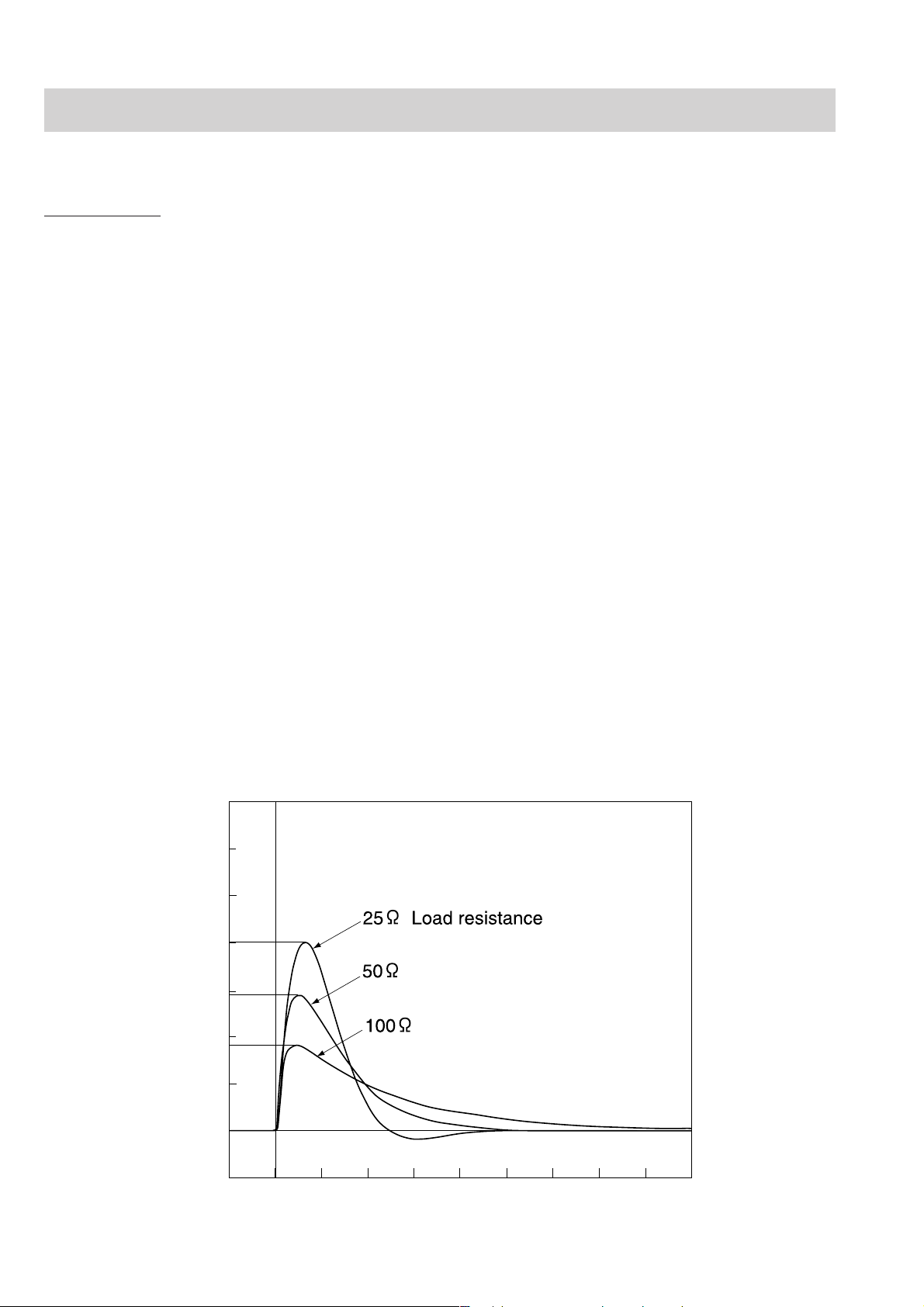
Output waveform Edmark, single phase pulse (across 50 Ω)
Charging time When powered by AC 100V to 240V:
to 360 J, maximum 5 s
to 200 J, maximum 3 s
When powered by 90% of the rated mains voltage:
to 360 J, maximum 5 s
When powered by a fully charged new battery at 20°C ambient temperature:
to 360 J, maximum 10 s
After 15 discharges at 360 J with a fully charged new battery at 20°C ambient
temperature: to 360J, maximum 10 s
Charging display Displays the charged energy value on the screen
Synchronized discharge Available
From the peak of R wave to the peak of discharge:
With paddle ECG: within 60 ms
With lead ECG or ECG from an external instrument: within 25 ms
Maximum continuous charge/discharge cycles at 360 J
60 cycles: 3 cycles per minute with 1 minute cool down period after every 1
minute charge/discharge period
15 cycles: 3 cycles per minute with no cool down period
Current
(Amps)
81A
58A
Delivered energy= 360J
37A
0A
0246810
1.6 Service Manual TEC-7600/7700
Time (ms)
TEC-7700 Seies
Output energy (across 50 Ω) 2, 3, 5, 7, 10, 15, 20, 30, 50, 70, 100, 150, 200 and 270 J
Energy accuracy 2 J: ±0.5 J
3 J: ±1 J
5 to 15 J: ±2 J
20 to 270 J: ±10%
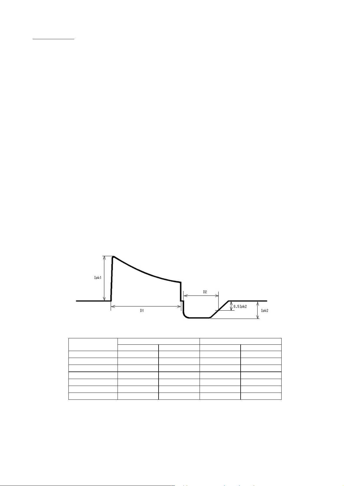
Output waveform Biphasic, truncated exponential constant power (across 50 Ω)
Charging time When powered by AC 100V to 240V:
to 270 J, maximum 5 s
to 150 J, maximum 3 s
When powered by 90% of the rated mains voltage:
to 270 J, maximum 5 s
When powered by a fully charged new battery at 20°C ambient temperatur e:
to 270 J, maximum 10 s
After 15 discharges at 270 J with a fully charged new battery at 20°C ambient
temperature: to 270J, maximum 10 s
Charging display Displays the charged energy value on the screen
Synchronized discharge Available
From the peak of R wave to the peak of discharge: within 60 ms
Maximum continuous charge/discharge cycles at 270 J
60 cycles: 3 cycles per minute with 1 minute cool down period after every 1
minute charge/discharge period
15 cycles: 3 cycles per minute with no cool down period
1. GENERAL
First phase Second phaseLoad resistance
(Ω)
Ipk1 (A) D1 (ms) Ipk2 (A) D2[ms]
25 67.3 3.85 15.5 3.62
50 41.1 6.35 12.7 3.62
75 29.5 8.86 11.0 3.62
100 22.9 11.4 9.81 3.62
125 18.8 13.9 8.96 3.62
150 15.9 16.4 8.29 3.62
175 13.8 18.9 7.76 3.62
Service Manual TEC-7600/7700 1.7

1. GENERAL
Non Invasive Blood pressure, NIBP (When optinal SG-761VC/VE/VK NIBP Unit is installed)
Display parameters: Systolic pressure, mean pressure, diastolic pressure, cuff pressure
Measuring range: 0 to 300 mmHg
Accuracy: ±3 mmHg (0 mmHg ≤ NIBP < 200 mmHg)
±4 mmHg (200 mmHg ≤ NIBP ≤ 300 mmHg)
Safety: Cuff inflation maximum pressure: Adult 300 to 330 mmHg
Neonate 150 to 165 mmHg
Cuff inflation time limiter: Adult ≤ 180 s
Neonates ≤ 90 s
When sudden power loss occurs, automatic rapid deflation is perofrmed.
Measurement mode: Manual
STAT (continuous)
Automatic (periodic)
Alarm: Adult
Upper limit range: 15 to 260 mmHg in 5 mmHg steps, OFF
Lower limit range: OFF, 10 to 255 mmHg in 5 mmHg steps
Neonate
Upper limit range: 10 to 125 mmHg in 5 mmHg steps, OFF
Lower limit range: OFF, 5 to 120 mmHg in 5 mmHg steps
Noninvasive Pacing (TEC-7631/7731 series only)
Pacing rate 40 to 180 pulse/min in 10 pulse/min steps
Output current 8 to 200 mA in 1 mA steps
Pacing modes Fixed and Demand
Maximum load resistance Outputs 200 mA across 250 Ω, 120 mA across 500 Ω
External Paddle (ND-782VC/VE/VK)
Paddle electrode size For adults: 70 ±3 × 10⁶ ±3 (mm2)
For children: 45 ±3 × 53 ±3 (mm2)
Paddle cord length 2.0 m or more (When it is pulled by 18 N force.)
Battery
Type Ni-MH battery
Nominal voltage: 12 V
Rated capacity: 2800 mAh
Capacity
TEC-7621/7631 series: With fully charged new battery at 20°C ambient temperature
- Minimum 70 discharges at 360 J
- Minimum 150 minutes continuous monitoring
- Minimum 90 minutes fixed mode pacing (180 pulse/min, 200 mA)
With the fully charged new battery at 0°C, the defibrillator can perform:
- Minimum 50 discharges at 360 J
TEC-7721/7731 series: With fully charged new battery at 20°C ambient temperature
- Minimum 100 discharges at 270 J
- Minimum 150 minutes continuous monitoring
- Minimum 90 minutes fixed mode pacing (180 pulse/min, 200 mA)
With the fully charged new battery at 0°C, the defibrillator can perform:
- Minimum 50 discharges at 270 J
1.8 Service Manual TEC-7600/7700

Clock Accuracy
At surrounding temeprature 25°C (77°F): ±3 min/month
At storage temperatures –20 to 70°C (–4 to 158°F): ±5 min/month
Environment
Operating temperature: 0 to 45°C (32 to 113°F)
Operating humidity: 0 to 40°C: 30 to 95% (relative humidity, non-condensing)
40 to 45°C: 30 to 80% (relative humidity, non-condensing)
Operating atmospheric pressure: 70 to 106 kPa
Storage temperature: –20 to 70°C (–4 to 158°F)
Storage humidity: 10 to 95% (relative humidity, non-condensing)
Storage atmospheric pressure: 50 to 106 kPa
Electromagnetic Compatibility
IEC 60601-1-2:1993
IEC 61000-3-2:1995
Emissions: CISPR11 Group1,Class B
1. GENERAL
Safety
Safety standard IEC 60601-1:1988
IEC 60601-1 Amendment 1:1991
IEC 60601-1 Amendment 2:1995
IEC 60601-2-4:1983
IEC 60601-2-30:1995
According to the type of protection against electrical shock
Battery power: INTERNALLY POWERED EQUIPMENT
AC power: CLASS I EQUIPMENT
According to the degree of protection against electrical shock
DEFIBRILLATION-PROOF TYPE BF APPLIED PART:
External paddles, disposable pads, SpO2 adapter and CO2 sensor kit, NIBP cuff
DEFIBRILLATION-PROOF TYPE CF APPLIED PART:
Internal paddles, ECG connection cable
According to the degree of protection against harmful ingress of water: IPX1
According to the degree of safety of applicationin the presence of a FLAMMABLE ANAESTHETIC MIXTURE
WITH AIR, OR WITH OXYGEN OR NITROUS OXIDE:
EQUIPMENT not suitable for use in the presence of FLAMMABLE ANAESTHETIC MIXTURE WITH AIR,
OR WITH OXYGEN OR NITROUS OXIDE
Mode of operation
Continuous operation with intermittent load: Operation at defibrillation mode
Continuous operation: All operation except above mentioned
Monitor
Effective display area 115.2(W) × 86.4(H) mm (5.7 inch)
Sweep length 97 mm
Sweep speed 25 mm/s, 50 mm/s
Sensitivity 10 mm/1mV ±5% (sensitivity × 1)
Amplitude limit 40 mm
Service Manual TEC-7600/7700 1.9

1. GENERAL
ECG Amplifier
Input signal PADDLE, I, II, III, aVR, aVL, aVF, V, AUX
Frequency response Through paddles: 0.5 to 20 Hz (–3 dB)
Through ECG connection cable: 0.05 to 80 Hz (–3 dB)
AUX: 0.05 to 80 Hz (–3 dB)
Input impedance Through paddles: ≥100 kΩ
Through ECG connection cable: ≥5 MΩ (at 10 Hz 1mV)
AUX: ≥ 100 kΩ ±10%
CMRR ≥100 dB (against chassis ground) when AC filter is On
AC filter Available (common with 50/60 Hz)
ON at ≥-20 dB, OFF
Pacing pulse rejection ON, OFF
External ECG input sensitivity 10 mm/V ± 5% (sensitivity × 1)
Heart rate counting range Defibrillation or monitoring mode: 15 to 300 bpm
Pacing mode: 15 to 220 bpm
Recorder
Paper speed Real time/delayed ECG waveform recording: 50, 25, 5 mm/s
Types of recording Manual recording:
real time/delayed waveform recording, report recording, event recording
Automatic recording:
record on charging after discharge, alarm recording, periodic recording
Rhythm Recognition Detector
We evaluated the rhythm recognition detector of the TEC-7600/7700 series defibrillator using the official
electrocardiogram database provided by AHA (American Heart Association) and MIT (Massachusetts Institute of
Technology) and an electrocardiogram database of over 3000 electrocardiograms from hospitals in Japan. According
to our own evaluation, the rhythm recognition detector of the TEC-7600/7700 series defibrillator meets the
equivalent of AAMI standards ANSI/AAMI DF-39-1993 3.3.18.
Power Requirements
AC
Line voltage: 100 to 240 V
Line frequency: 50/60 Hz (automatic switching)
Power input: Intermittent load: 450 VA or less
Continuous load: 200 VA or less
DC (Battery)
Power voltage: 12V
Power consumption Intermittent load: 14 A or less
Continuous load: 4.2 A or less
Charging time: 3 hours or less (with AC, with the power OFF)
1.10 Service Manual TEC-7600/7700

Dimensions and Weight
Dimensions 336W × 242H ×377 D mm
Weight
TEC-7621 series defibrillator:
7.8 kg (External paddles use, AC unit w/o battery)
6.9 kg (Pad adaptor use, AC unit w/o battery)
TEC-7631 series defibrillator:
8.1 kg (External paddles use, AC unit w/o battery)
7.2 kg (Pad adaptor use, AC unit w/o battery)
TEC-7721 series defibrillator:
8.1 kg (External paddles use, AC unit w/o battery)
7.2 kg (Pad adaptor use, AC unit w/o battery)
TEC-7731 series defibrillator:
8.4 kg (External paddles use, AC unit w/o battery)
7.5 kg (Pad adaptor use, AC unit w/o battery)
1. GENERAL
Service Manual TEC-7600/7700 1.11

1. GENERAL
Panel Description
Front Panel
TEC-7600 Series
7
8
TEC-7700 Series
7
1
CardioLife
PACING
DISARM
DEMAND
FIXED
AED
SETUP
MONITOR
OFF
SYNC
CHARGE
AED
3
DISARM
AED
MONITOR
OFF
SYNC
2
FIXED
SETUP
CHARGE
AED
PACING
DEMAND
5
DISCHARGE
10
4
9
6
1
CardioLife
PACING
DISARMS
DEMAND
FIXED
AED
SETUP
MONITOR
OFF
SYNC
CHARGE
AED
DISARMS
AED
3
MONITOR
OFF
SYNC
2
FIXED
SETUP
CHARGE
AED
PACING
DEMAND
5
8
10
4
DISCHARGE
9
6
Name
1. Energy/Mode Select control
2. SYNC button
3. SYNC lamp
4. CHARGE/AED button
5. CHARGE button
6. DISCHARGE button
7. Screen
8. ECG input connector
9. SpO2/CO2 connector (on the optional QI-762V DSI Interface Unit)
10. Paddle connector
1.12 Service Manual TEC-7600/7700
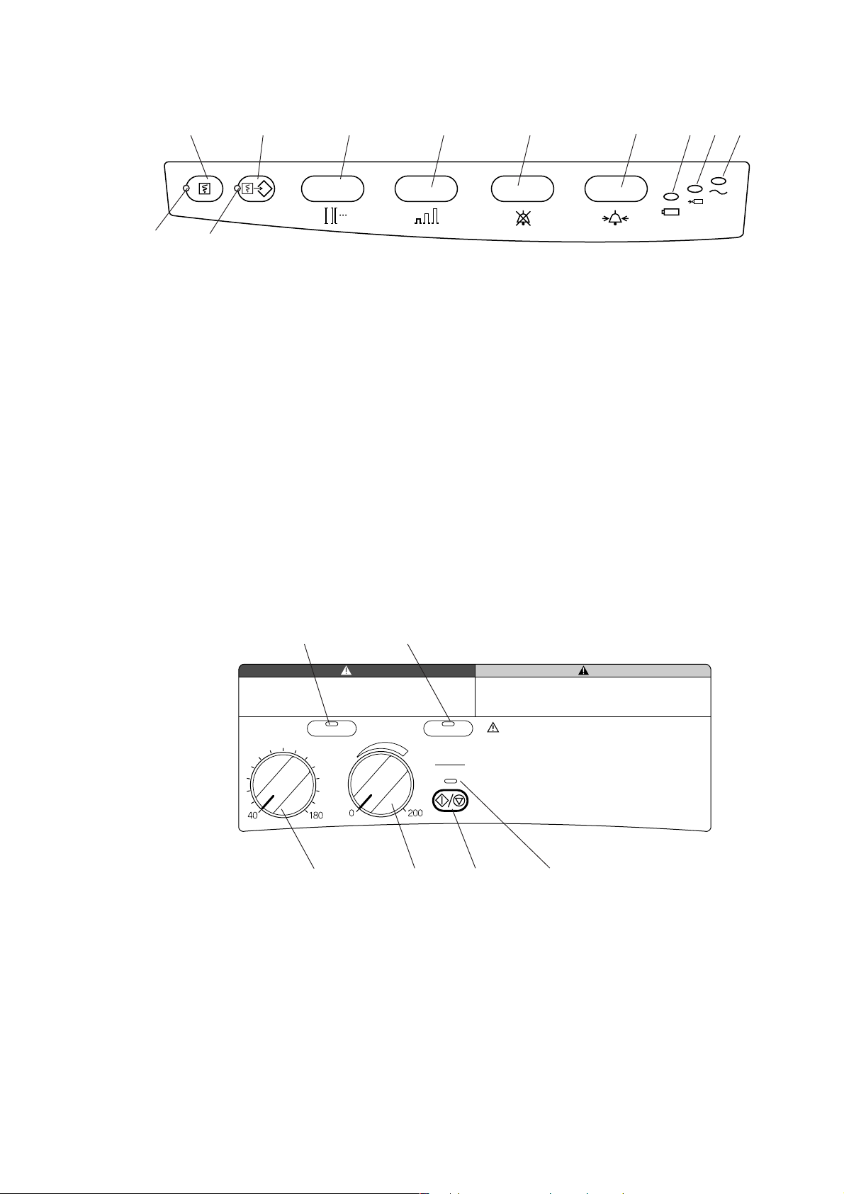
1. GENERAL
12
14
13
15 16
Name
11. Record key
12. Recording lamp
13. Event key
14. Event lamp
15. ECG lead key
16. ECG sensitivity key
17. SILENCE ALARM key
18. Alarm setting key
19. AC lamp
20. Battery charging lamp
21. Battery charge complete lamp
17
21
20 191811
Top Panel (TEC-7631/7731 Series Only)
3
PACING
RATE(ppm)
PACING
1
PACING
OUTPUT(mA)
Name
1. PACING RATE control
2. PACING OUTPUT control
3. PACING lamp
4. START/STOP key
5. START/STOP lamp
6. PULSE lamp
6
PULSE
START
STOP
2
54
Service Manual TEC-7600/7700 1.13
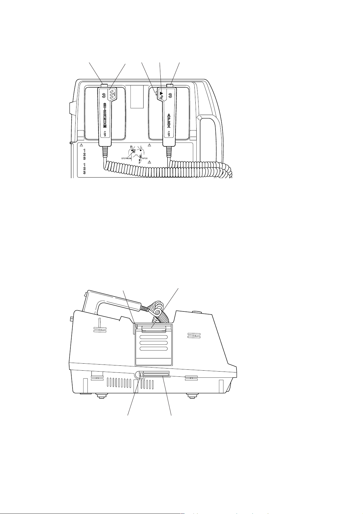
1. GENERAL
External Paddles
14432
Name
1. CONTACT lamp
2. CHARGE button
3. CHARGE lamp
4. DISCHARGE buttons
Left Side Panel
2
43
1
Name
1. Recording paper exit
2. Door release lever
3. Card slot
4. Card eject button
1.14 Service Manual TEC-7600/7700

Rear Panel
1. GENERAL
1
2
Name
1. AC SOURCE socket
2. Equipotential ground terminal
3. Optional unit connector
3
Bottom Panel
Battery pack holder
Service Manual TEC-7600/7700 1.15
1. GENERAL
Composition
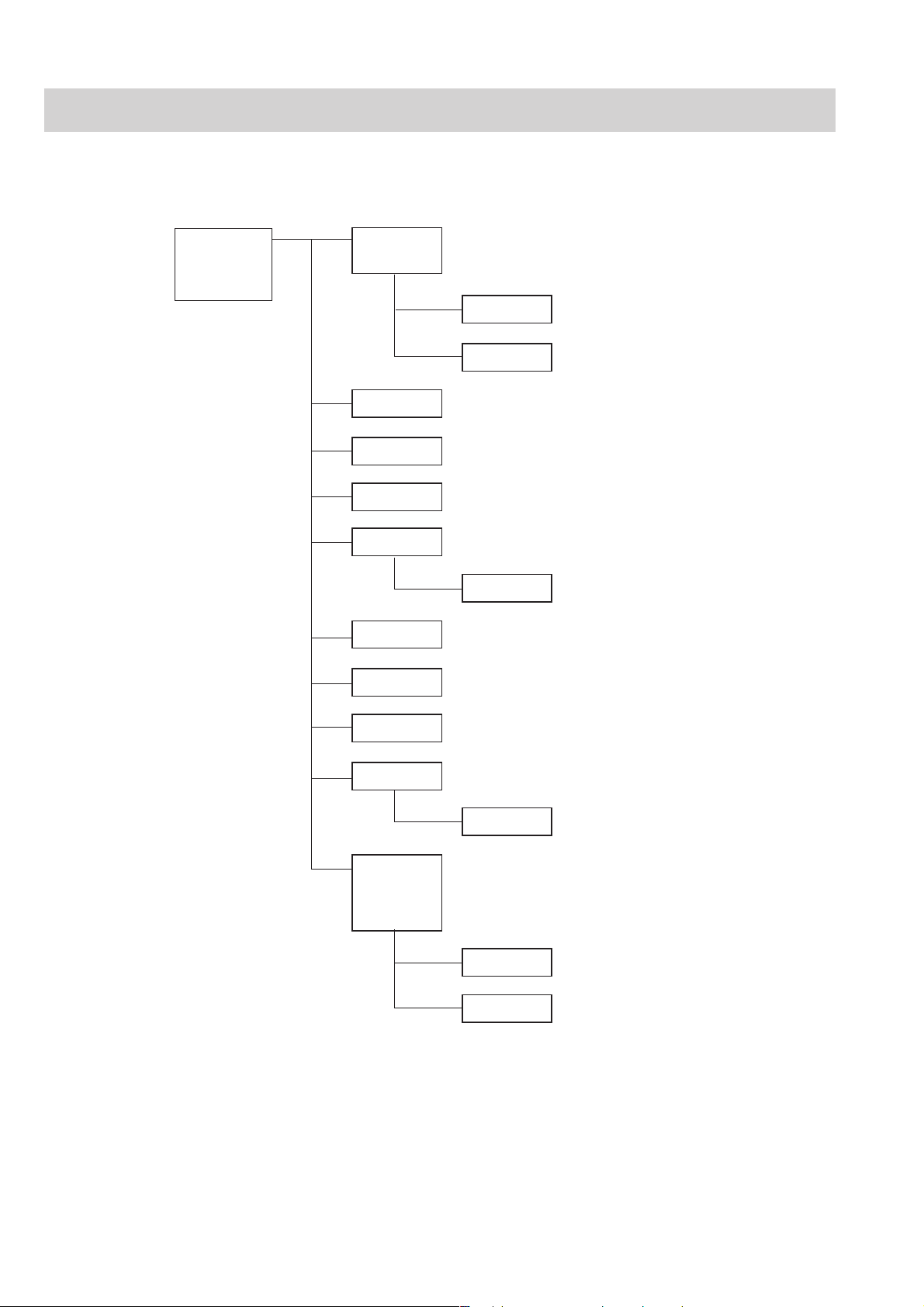
Standard Components
TEC-7621C
TEC-7621E
TEC-7621K
CY-0006 Upper casing assy for E/K version
CY-0014 Upper casing assy for C version
UR-0249 Main key board
UR-0251 Test load board
CY-0007 Lower casing assy
CY-0008 LCD assy
CY-0009 PRE assy
HV-761V Relay unit
UR-0121 HV drive board
UR-0247 Main board
UR-0250 Key board
UR-0262 AC/DC unit
WS-761V Recorder unit
WS-751X Recorder
ND-782VC External paddle for C version
ND-782VE External paddle for E version
ND-782VK External paddle for K version
ND-611V Adult plate assy
ND-782X External paddle assy
1.16 Service Manual TEC-7600/7700
1. GENERAL
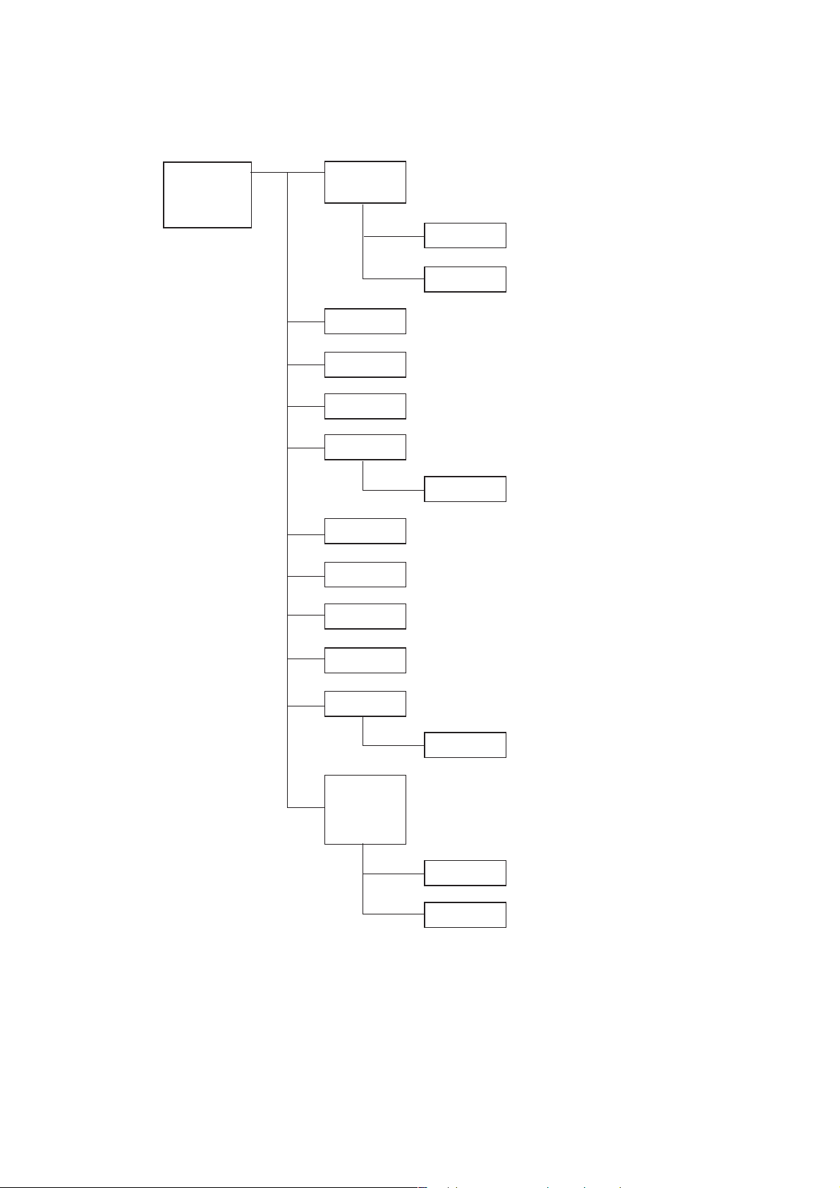
TEC-7631C
TEC-7631E
TEC-7631K
CY-0006 Upper casing assy for E/K version
CY-0014 Upper casing assy for C version
UR-0249 Main key board
UR-0251 Test load board
CY-0007 Lower casing assy
CY-0008 LCD assy
CY-0009 PRE assy
HV-761V Relay unit
UR-0121 HV drive board
UR-0247 Main board
UR-0253 Pacer board
UR-0250 Key board
UR-0262 AC/DC unit
WS-761V Recorder unit
WS-751X Recorder
ND-782VC External paddle for C version
ND-782VE External paddle for E version
ND-782VK External paddle for K version
ND-611V Adult plate assy
ND-782X External paddle assy
Service Manual TEC-7600/7700 1.17
1. GENERAL
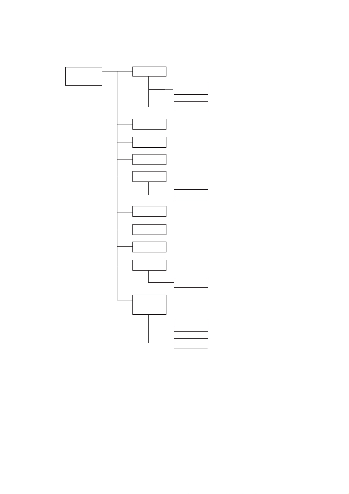
TEC-7721E
TEC-7721K
CY-0011 Upper casing assy
UR-0249 Main key board
UR-0251 Test load board
CY-0012 Lower casing assy
CY-0008 LCD assy
CY-0009 PRE assy
HV-771V Biphasic HV unit
UR-0248 T-HV drive board
UR-02471 Main board
UR-0250 Key board
UR-0262 AC/DC unit
WS-761V Recorder unit
WS-751X Recorder
ND-782VE External paddle for E version
ND-782VK External paddle for K version
ND-611V Adult plate assy
ND-782X External paddle assy
1.18 Service Manual TEC-7600/7700
1. GENERAL
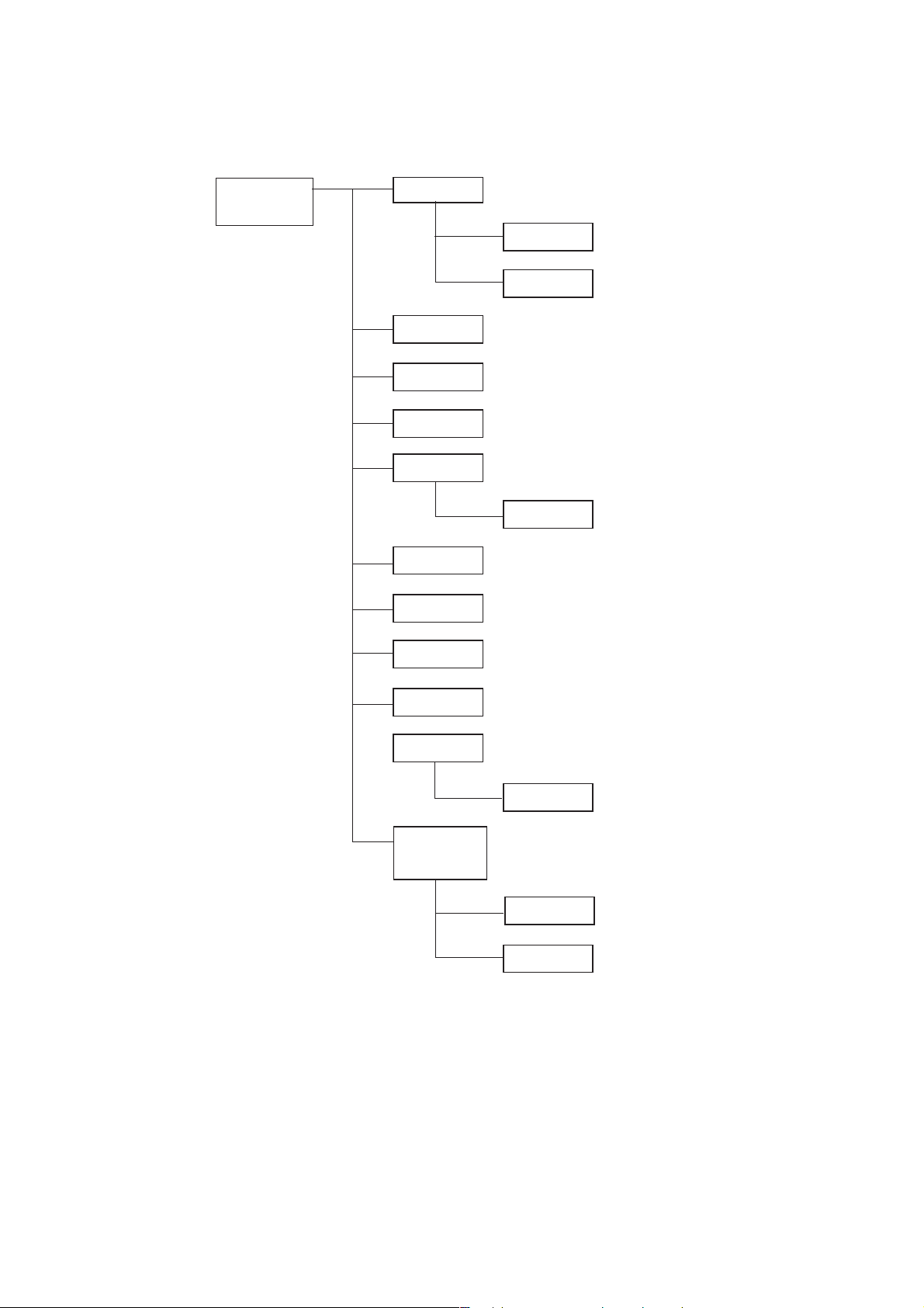
TEC-7731E
TEC-7731K
CY-0011 Upper casing assy
UR-0249 Main key board
UR-0251 Test load board
CY-0012 Lower cassing assy
CY-0008 LCD assy
CY-0009 PRE assy
HV-771V Biphasic HV unit
UR-0248 T-HV drive board
UR-02471 Main board
UR-0253 Pacer board
UR-0250 Key board
UR-0262 AC/DC unit
WS-761V Recorder unit
WS-751X Recorder
ND-782VE External paddle for E version
ND-782VK External paddle for K version
ND-611V Adult plate assy
ND-782X External paddel assy
Service Manual TEC-7600/7700 1.19
 Loading...