


Nihon-Kohden ECG-9010 Service manual

SERVICE MANUAL
cardiofax GEM
ELECTROCARDIOGRAPH
ECG-9010K, ECG-9020K
ECG-9020P, ECG-9022K
0634-001307B

CONTENTS
Contents
Conventions Used in this Manual and Instrument ....................................................................i
Warnings, Cautions and Notes ....................................................................................... i
Explanations of the Symbols in this Manual and Instrument .......................................... i
Section 1 General .................................................................................. 1C.1
Introduction .......................................................................................................................... 1.1
Service Policy ......................................................................................................................1.2
Specifications ...................................................................................................................... 1.3
Panel Description ................................................................................................................. 1.5
ECG-9010K Electrocardiograph ..................................................................................1.5
Top View ........................................................................................................... 1.5
Operation Panel................................................................................................1.6
Right Side Panel ..............................................................................................1.7
ECG-9020K/P Electrocardiograph .............................................................................. 1.8
Top View ........................................................................................................... 1.8
Operation Panel................................................................................................1.9
Right Side Panel ............................................................................................ 1.10
ECG-9022K Electrocardiograph ................................................................................ 1.11
Top View ......................................................................................................... 1.11
Operation Panel.............................................................................................. 1.12
Right Side Panel ............................................................................................ 1.13
Composition ....................................................................................................................... 1.14
ECG-9010K Electrocardiograph ................................................................................ 1.14
ECG-9020K Electrocardiograph ................................................................................ 1.15
ECG-9020P Electrocardiograph ................................................................................ 1.16
ECG-9022K Electrocardiograph ................................................................................ 1.17
Location .............................................................................................................................. 1.18
Block Diagram .................................................................................................................... 1.19
Connection Diagram ........................................................................................................... 1.20
Section 2 Maintenance ......................................................................... 2C.1
Replacement ........................................................................................................................ 2.1
Periodic Replacement Schedule ................................................................................. 2.1
Cleaning ...............................................................................................................................2.2
Cleaning and Greasing Schedules.............................................................................. 2.2
Cleaning the Paper Mark Sensor and Paper Empty Sensor ........................................ 2.2
Cleaning the Motor Rotation Sensor and
Greasing the Motor Gear and Gear Meshed with Motor Gear .....................................2.3
Section 3 Troubleshooting and System Error Message .................. 3C.1
Troubleshooting Flowchart .................................................................................................... 3.1
Troubleshooting Table ...........................................................................................................3.4
Service Manual ECG-9010/9020 Rev B C.1

CONTENTS
Troubleshooting General Operation Problem............................................................... 3.4
Troubleshooting Recording Problem ........................................................................... 3.6
System Error Message ......................................................................................................... 3.7
Section 4 System Test, Adjustment and Setting................................ 4C.1
System Test ......................................................................................................................... 4.1
Overall ........................................................................................................................ 4.1
Calling up the Test Level 1 .........................................................................................4.2
Calling up the Test Level 2 .........................................................................................4.3
Entering the System Test Number .............................................................................. 4.4
Executing the System Test ........................................................................................ 4.5
Quitting the System Test ............................................................................................ 4.6
Exiting the System Test Mode ................................................................................... 4.6
Demonstration ......................................................................................................................4.7
Recorder ...............................................................................................................................4.8
Thermal Head ..................................................................................................................... 4.11
Key .....................................................................................................................................4.12
Memory .............................................................................................................................. 4.13
Single Memory Test Mode ........................................................................................ 4.14
Continuous Memory Test Mode ................................................................................ 4.14
LCD/LED ............................................................................................................................4.15
Input Unit ........................................................................................................................... 4.17
Calibration .......................................................................................................................... 4.18
Communication .................................................................................................................. 4.19
CRO/EXT1 ......................................................................................................................... 4.21
System Setup Initialization ................................................................................................ 4.23
ECG Findings List Recording ............................................................................................. 4.24
Recording Resolution Setting ............................................................................................. 4.25
Cue Mark Adjustment ......................................................................................................... 4.26
Date and Time Setting ........................................................................................................ 4.28
Setting the Date and Time ............................................................................. 4.28
Section 5 Board/Unit Description ..........................................................5C.1
Block Diagram..................................................................................................................... 5.1
Power Unit ........................................................................................................................... 5.2
ECG Control Board ............................................................................................................. 5.2
Flash ROM Board ............................................................................................................... 5.3
Inverter Board ..................................................................................................................... 5.3
Section 6 Disassembly and Assembly ..................................................6C.1
Before You Begin ................................................................................................................. 6.1
Warnings and Cautions ............................................................................................ 6.1
Required Tools .......................................................................................................... 6.1
Board and Unit Location ........................................................................................... 6.2
Cable Connection ..................................................................................................... 6.3
Removing the Top Casing .....................................................................................................6.4
C.2 Service Manual ECG-9010/9020 Rev B

CONTENTS
Removing the LCD Assy ...................................................................................................... 6.5
Removing the Thermal Head Assy .......................................................................................6.6
Removing the Motor Assy ....................................................................................................6.8
Removing the Speaker Assy ................................................................................................ 6.9
Removing the Inverter Board ............................................................................................. 6.10
Removing the ECG Control Board ...................................................................................... 6.11
Removing the Power Unit ................................................................................................... 6.12
Replacing the Thermistor and Termistor Cable .......................................................... 6.14
Removing the Battery Terminal Assy .................................................................................. 6.15
Removing the Magazine Assy............................................................................................ 6.16
Removing the Bottom Casing ............................................................................................. 6.17
Replacing the Fuse on the Power Board .............................................................................6.18
Replacing the Lithium Battery on the ECG Control Board ................................................... 6.19
Section 7 Replaceable Parts List......................................................... 7C.1
General Parts List ................................................................................................................7.2
Top Casing Assy .................................................................................................................. 7.4
Top Casing Assy, RK-0007 for ECG-9010K ................................................................7.4
Top Casing Assy, RK-0009 for ECG-9020K ................................................................7.5
Top Casing Assy, RK-0044 for ECG-9020P ................................................................7.6
Top Casing Assy, RK-0058 for ECG-9022K ................................................................7.7
Thermal Head Assy, YZ-011H8 ............................................................................................7.8
Motor Assy, GC-0011 ...........................................................................................................7.9
Speaker Assy, RK-0005 ..................................................................................................... 7.10
Magazine Assy, RH-0001 ................................................................................................... 7.11
Battery Terminal Assy, RK-0006 ......................................................................................... 7.12
LCD Assy, VL-0001 ............................................................................................................ 7.13
Patient Cable Hanger .......................................................................................................... 7.14
Section 8 Connector Pin Assignment ................................................ 8C.1
Power Unit ............................................................................................................................ 8.1
CN11 (to AC Inlet) ......................................................................................................8.1
CN21 (to ECG control board) ...................................................................................... 8.1
CN31 (to Thermal Head) ............................................................................................. 8.1
CN51 (to Battery) ....................................................................................................... 8.1
ECG Control Board ............................................................................................................... 8.2
CNJ011 (to Thermal Head) ......................................................................................... 8.2
CNJ012 (to Inverter Board) ........................................................................................ 8.2
CNJ013 (to LCD) ........................................................................................................ 8.3
CNJ021 (to Flash ROM Board) ................................................................................... 8.3
CNJ031 (to SIO Connector) ....................................................................................... 8.5
CNJ032 (to Key Connector)........................................................................................8.5
CNJ033 (to Speaker) ..................................................................................................8.6
CNJ035 (to Power Unit) .............................................................................................. 8.7
CNJ036 (to Motor) ......................................................................................................8.8
CNJ041 (to CRO Connector) ...................................................................................... 8.8
CNJ043 (to EXT INPUT Connector) ........................................................................... 8.8
Service Manual ECG-9010/9020 Rev B C.3

CONTENTS
CNJ091 (to ECG Connector) ...................................................................................... 8.9
Flash ROM Board ............................................................................................................... 8.10
CNJ021 (to ECG Control Board) ...............................................................................8.10
Inverter Board .................................................................................................................... 8.12
CN1 (to ECG Control Borad) .................................................................................... 8.12
CN2 (to LCD module) ............................................................................................... 8.12
External Input/Output Socket .............................................................................................8.13
SIO Socket .............................................................................................................. 8.13
EXT Input and CRO Output ...................................................................................... 8.13
C.4 Service Manual ECG-9010/9020 Rev B
Conventions Used in this Manual and Instrument
Warnings, Cautions and Notes
Warnings, cautions and notes are used in this manual to alert or signal the reader to specific information.
WARNING
A warning alerts the user to the possible injury or death associated with the use or misuse of the
instrument.
CAUTION
A caution alerts the user to possible injury or problems with the instrument associated with its use or
misuse such as instrument malfunction, instrument failure, damage to the instrument, or damage to other
property.
NOTE
A note provides specific inf ormation, in the form of recommendations, prerequirements, alternative
methods or supplemental information.
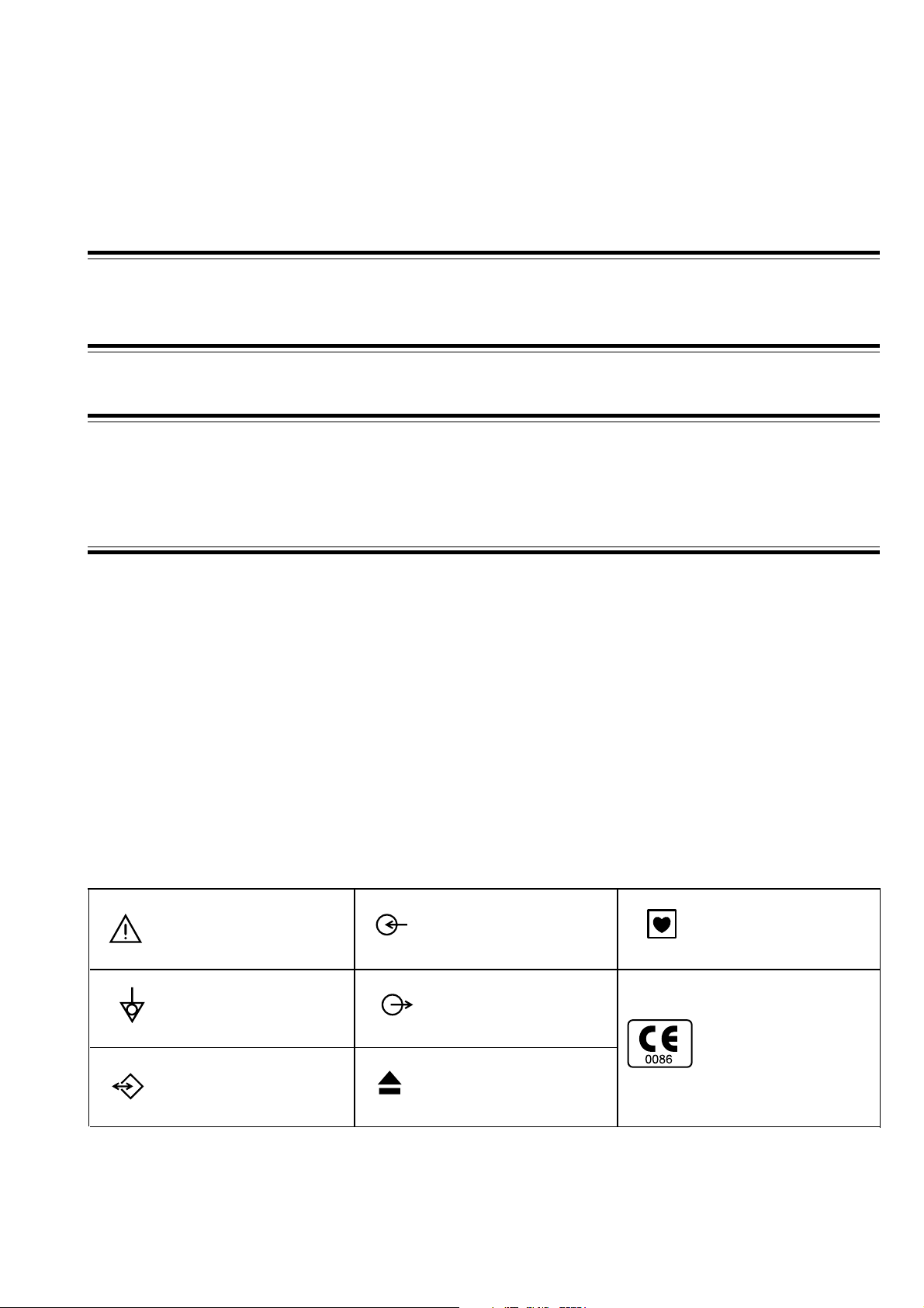
Explanations of the Symbols in this Manual and Instrument
The following symbols found in this manual/instrument bear the respective descriptions as given.
Cardiograph
Attention, consult
operator’s manual
Equipotential terminal
Serial input/output terminal
Input terminal for analog
signal
Output terminal for analog
signal
Eject (magazine release
button)
Type CF applied part
The CE mark is a protected
conformity mark of
European Community.
The products herewith
comply with the
requirements of the
Medical Device Directive
93/42/EEC.
Service Manual ECG-9010/9020 Rev A i
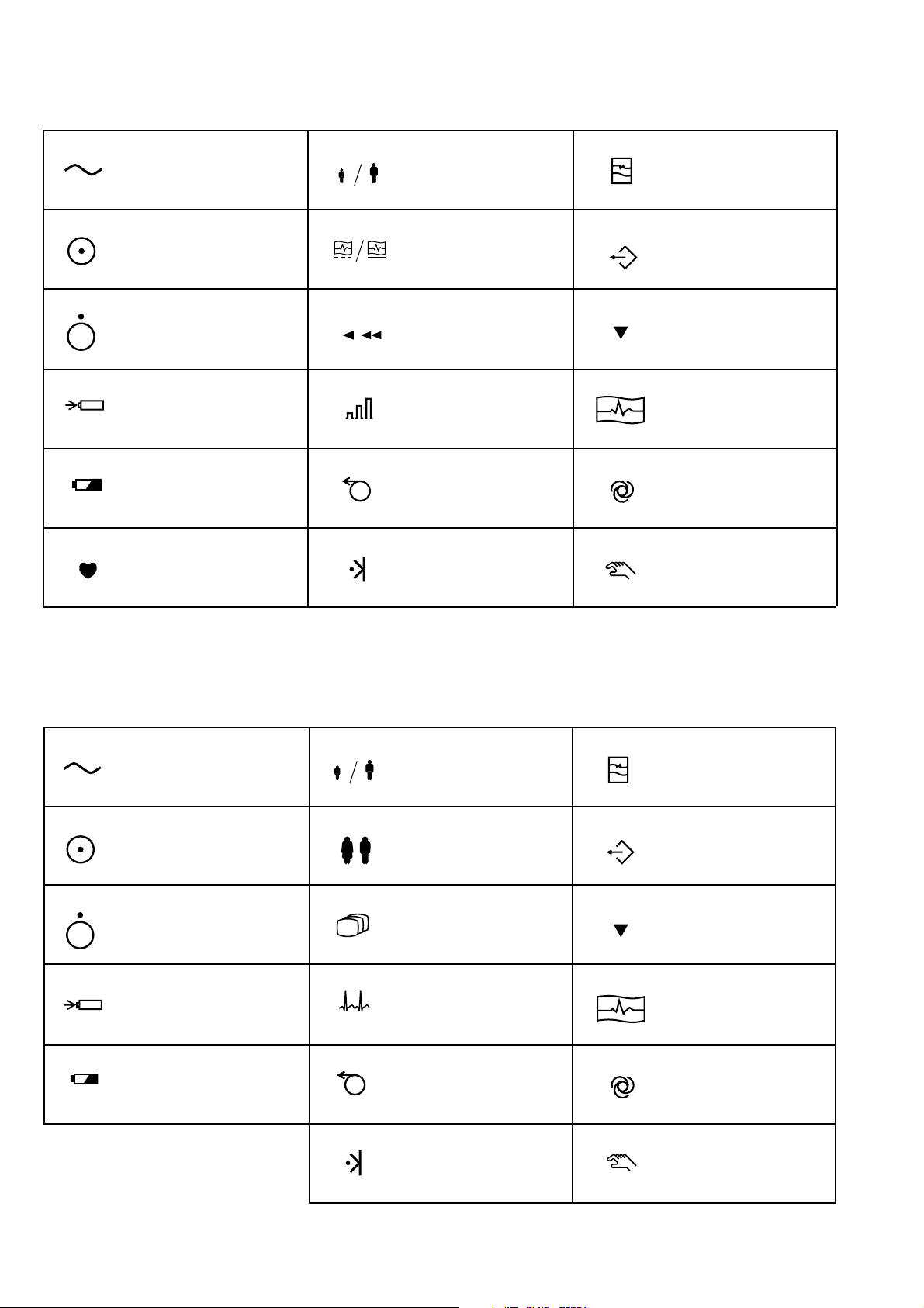
Operation panel (for ECG-9010K onlly)
Alternating current
“On” only for a part of
equipment
“Off” only for a part of
equipment
Battery charging (lamp/on
screen)
Battery check (lamp/on
screen)
QRS sync lamp
Age
REST/PERIODIC
recording
Paper speed
Gain
Paper feed
Mark
Filter
Copy
Calibration
START/STOP recording
Automatic control
Manual control
Operation panel (for ECG-9020K only)
Alternating current
“On” only for a part of
equipment
“Off” only for a part of
equipment
Battery charging (lamp/on
screen)
Battery check (lamp/on
screen)
Age
Sex
Mode
Rhythm
Paper feed
Filter
Copy
Calibration
START/STOP recording
Automatic control
Mark
ii Service Manual ECG-9010/9020 Rev A
Manual control
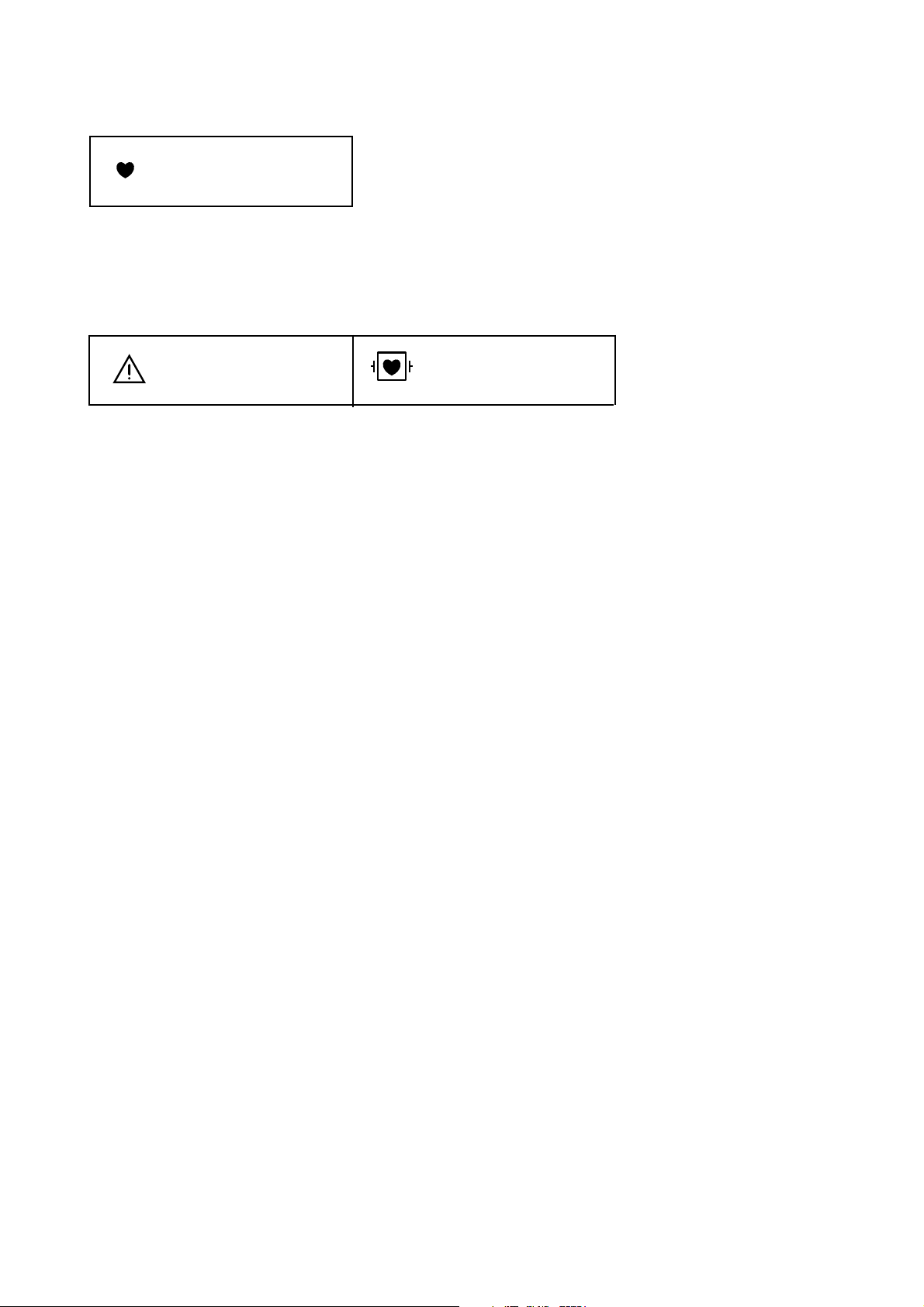
Display (for ECG-9020K only)
QRS sync lamp
Patient cable
Attention, consult
operator’s manual
Defibrillation-proof
Type CF applied part
Service Manual ECG-9010/9020 Rev A iii

Section 1 General
Introduction ........................................................................................................................ 1.1
Service Policy .................................................................................................................... 1.2
Specifications ..................................................................................................................... 1.3
Panel Description ............................................................................................................... 1.5
ECG-9010K Electrocardiograph .............................................................................. 1.5
Top View ........................................................................................................ 1.5
Operation Panel ............................................................................................. 1.6
Right Side Panel ............................................................................................ 1.7
ECG-9020K/P Electrocardiograph ........................................................................... 1.8
Top View ........................................................................................................ 1.8
Operation Panel ............................................................................................. 1.9
Right Side Panel .......................................................................................... 1.10
ECG-9022K Electrocardiograph ............................................................................ 1.11
Top View ...................................................................................................... 1.11
Operation Panel ........................................................................................... 1.12
Right Side Panel .......................................................................................... 1.13
Composition ..................................................................................................................... 1.14
ECG-9010K Electrocardiograph ............................................................................ 1.14
ECG-9020K Electrocardiograph ............................................................................ 1.15
ECG-9020P Electrocardiograph ............................................................................ 1.16
ECG-9022K Electrocardiograph ............................................................................ 1.17
Location ........................................................................................................................... 1.18
Block Diagram.................................................................................................................. 1.19
Connection Diagram ........................................................................................................ 1.20
Service Manual ECG-9010/9020 Rev B 1C.1

Introduction
1. GENERAL
This service manual provides useful information to qualified service personnel to
understand, troubleshoot, service, maintain and repair the ECG-9010K, ECG-
9020K/P and ECG-9022K Electrocardiograph (referred to in this service manual
as “the instrument”, “ECG-9010K” or “ECG-9020K” which includes ECG-9020P
and ECG-9022K).
All replaceable parts or units of this instrument and its optional units are clearly
listed with exploded illustration to help you locate the parts quickly.
The System test, Adjustment and Setting section in this service manual describes
the maintenance that should be performed by qualified service personnel. The
Maintenance section in the operator’s manual describes the maintenance that can
be performed by the user.
The information in the operator’s manual is primarily for the user. However, it is
important for service personnel to thoroughly read the operator’s manual and
service manual before starting to troubleshoot, service, maintain or repair this
instrument. This is because service personnel needs to understand the operation of
the instrument in order to effectively use the information in the service manual.
Service Manual ECG-9010/9020 Rev B 1.1

1. GENERAL
Service Policy
Nihon Kohden Corporation’s basic policy for technical service is to replace faulty
units, printed circuit boards or parts. We do not support component-level repair of
boards and units outside the factory for the following reasons:
• A special facility is necessary to repair multi-layer boards because most of the
components on the board are SMD (surface mount devices) and most of the
circuits employ a gate array method.
• To fulfill safety certification requirements, a special facility is necessary to verify
safety as medical equipment after the power unit is repaired.
NOTE
• When ordering parts or accessories from your nearest Nihon Kohden
Corporation’s distributor, please quote the NK code number and part
name which is listed in this service manual, and the name or model
of the unit in which the required part is located. This will help us to
promptly attend to your needs.
• Always use parts and accessories recommended or supplied by
Nihon Kohden Corporation to assure maximum performance from
your instrument.
1.2 Service Manual ECG-9010/9020 Rev B

Specifications
ECG input
Input impedance 10 MΩ or more
Electrode offset tolerance ±500 mV or more
Input unit protection Isolated and defibrillator protected
Standard sensitivity 10 mm /mV ±2%
Common mode rejection ratio 100 dB or more
Frequency response 0.05 to 150 Hz (– 3 dB or more)
Waveform data processor
Sample rate 500 samples/s (input unit: 8,000 samples/s)
AC line filter 50/60 Hz, OFF
High-cut filter 75, 100, 150 Hz
EMG filter 25/35 Hz
Time constant 3.2 s or more
Waveform status detection Electrode detachment (polarization voltage),
Sensitivity selection 5, 10 , 20 mm/mV
1. GENERAL
Noise (high frequency)
LCD (monochrome with CCFT backlight) (for ECG-9020K/P, ECG-9022K only)
Size 5.6 inch
Number of dots 320 × 240
ECG waveform 3 channel:Real time 12 ECG lead complexes
6 channel: 2.5 s
Rhythm lead: 10 s
Displayed data Waveform, patient information, recording settings,
operation mode, heart rate, QRS sync mark, error message,
electrode detachment, noise
Recorder
Printing method High resolution thermal printer head
Printing density 200 dpi (8 dots/mm)
Scanning line density 1 ms
Recording width 104 mm
Number of recording channels 2, 3, 4, 6
Paper speed 10, 12.5, 25, 50 mm/s
(10 and 12.5 mm/s available for ECG-9020K only)
Printed data Program type, version, date and time, paper speed, sensitivity,
lead name, filter, hospital name, patient information,
timing mark, event mark, electrode detachment, noise
Mechanical noise 48 dB or less at paper speed 25 mm/s
External input/output
External input 10 mm/0.5 V ±5%, input impedance 100 kΩ or more
Signal output 0.5 V/1 mV ±5%, output impedance 100 Ω or less
Serial I/O Communication method: RS-232C
Baud rate: 2400, 4800, 9600, 19200, 38400,
57600, 115200
Service Manual ECG-9010/9020 Rev B 1.3

1. GENERAL
Power requirement
Line voltage 100 to 127 VAC, 220 to 240 VAC ±10%
Line frequency 50 or 60 Hz
Power input Up to 120 VA
Power consumption 49 W or less
Built-in battery Voltage: 12 V
(LCT-1912ANK) Current consumption: 6A or less
Environment
Operating temperature 10 to 40°C
Operating humidity 25 to 90% RH
Operating atmospheric pressure 70 to 106 kPa
Storage duration and temperature 2 weeks or less: −20 to 65°C
(Depends on the battery) Between 2 weeks and One year: −15 to 40°C
Over one year: −15 to 25°C
Storage humidity 10 to 95% RH (non condensing)
Storage atmospheric pressure 70 to 106 kPa
Recording paper storage temperature −20 to 50°C
Recording paper storage humidity 25 to 90% RH
Electromagnetic compatibility Class B
Other Indoor portable
Dimensions and weight
Dimensions 280 W × 52 H × 216 D mm (excluding protrusions)
Weight ECG-9010K: Approx. 1.9 kg (without battery)
ECG-9020K/P: Approx. 2.1 kg (without battery)
ECG-9022K: Approx. 2.1 kg (without battery)
Safety
Safety standard:
IEC 60601-1 (1988), IEC 60601-1 Amendment 1 (1991), IEC 60601-1 Amendment 2 (1995)
IEC 60601-2-25 (1993), IEC 60601-2-25 Amendment 1 (1999)
Type of protection against electric shock:
AC power: Class I
Batty power: Internally powered equipment
Degree of protection against electric shock:
Defibrillator proof type CF applied part when patient cable BJ-901D, BJ-902D or BJ-903D is
used
Degree of protection against harmful ingress of water:
Ordinary equipment
Degree of safety of application in the presence of a flammable anaesthetic mixture with air, oxygen
or nitrous oxide:
Not suitable for use in the presence of a flammable anaesthetic mixture with air, oxygen or
nitrous oxide
Mode of operation: Continuous
Performance
Performance standard: IEC 60601-2-51 (2003)
1.4 Service Manual ECG-9010/9020 Rev B
Panel Description
1. GENERAL
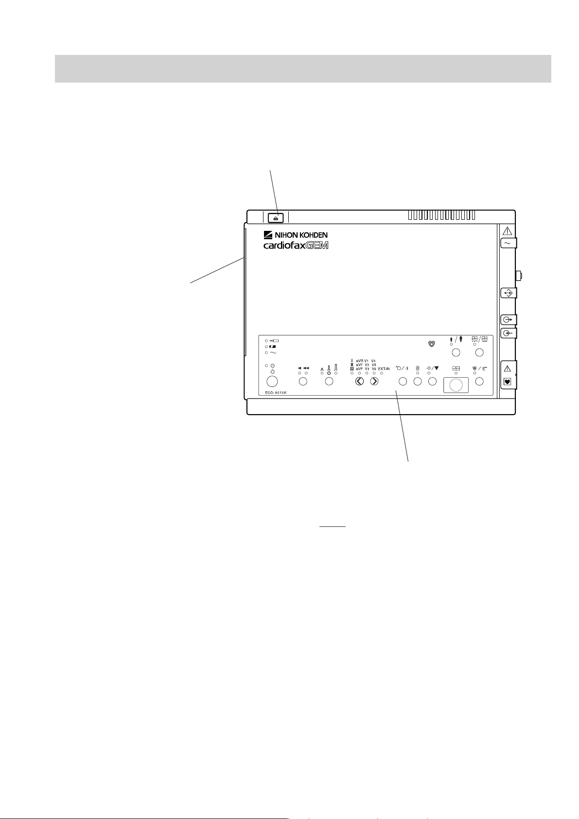
ECG-9010K Electrocardiograph
Top View
3
2
1
Name
1. Operation panel
2. Magazine (recording paper container)
3. Magazine release button
Service Manual ECG-9010/9020 Rev B 1.5
1. GENERAL
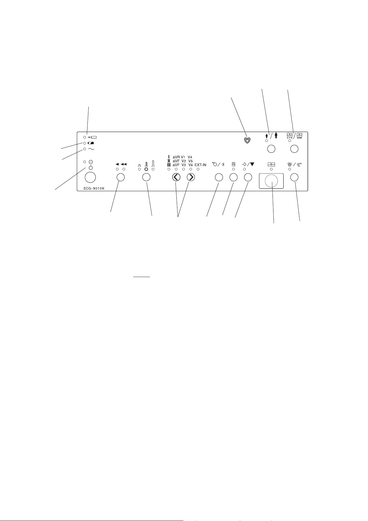
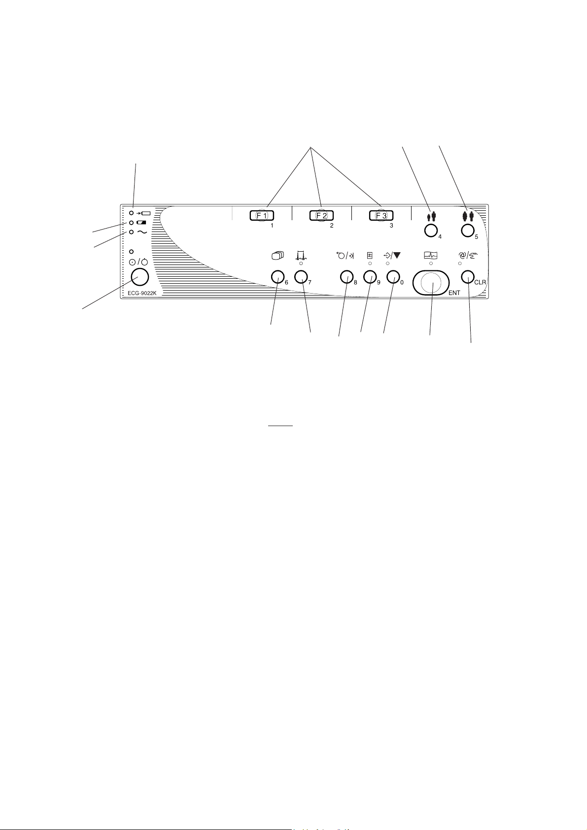
Operation Panel
14
18
4
5
6
7
15
16
17
9
8
10
11
13
12
Name
4. Battery charge lamp
5. Battery operation lamp
6. AC power lamp
7. POWER key/lamp
8. FEED/MARK key
9. FILTER key/lamp
10. COPY/CAL key/lamp
11. START/STOP key/lamp
12. AUTO/MANUAL key/lamp
13. REST/PERIODIC key/lamp
14. AGE key/lamp
15. SPEED key/lamp
16. GAIN key/lamp
17. LEAD keys/lamp
18. QRS sync lamp
1.6 Service Manual ECG-9010/9020 Rev B
1. GENERAL
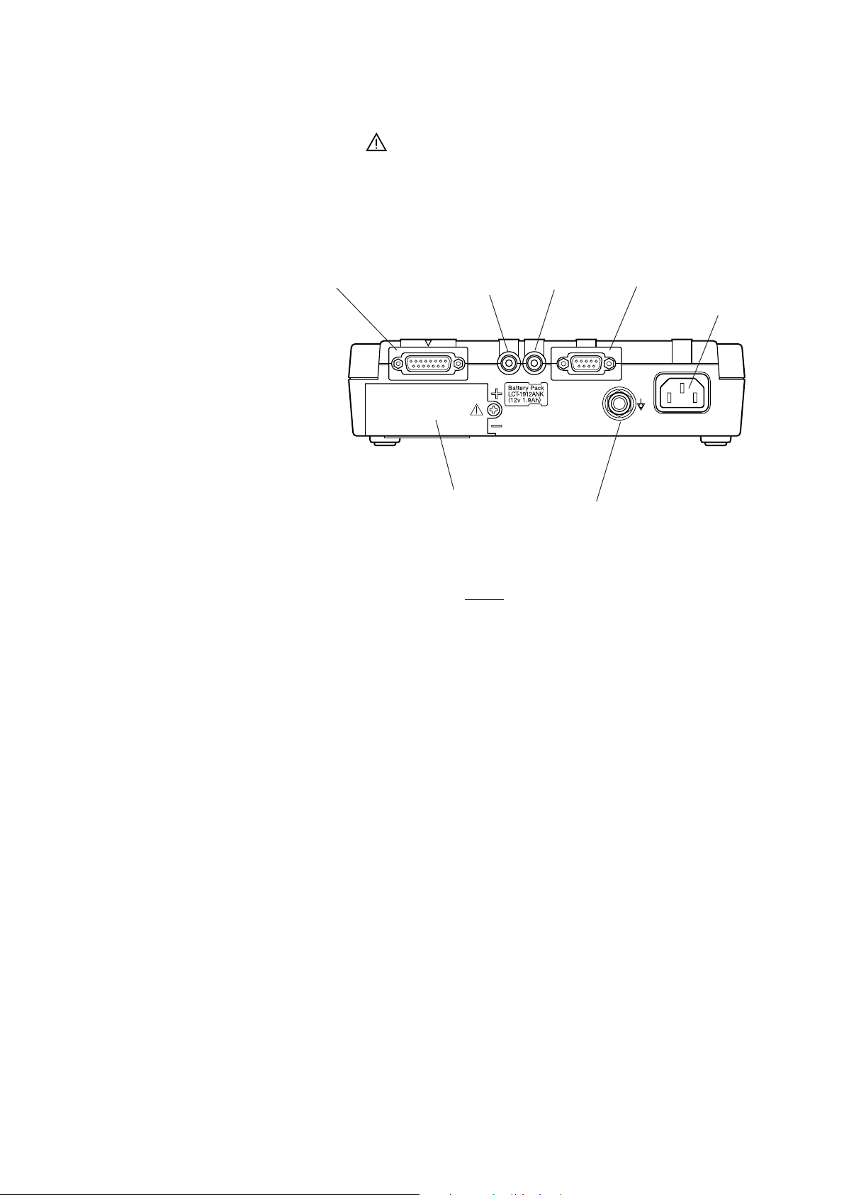
Right Side Panel
For the mark, refer to the descriptions for the Right Side Panel in Section 1
“Panel Descriptions” of the ECG-9010K Operator’s Manual.
19
20
24
Name
19. Patient input connector
20. EXT-IN connector
21. CRO-OUT
22. SIO connector
23. AC power cord socket
24. Battery compartment
25. Equipotential ground terminal
21
25
22
23
Service Manual ECG-9010/9020 Rev B 1.7

1. GENERAL
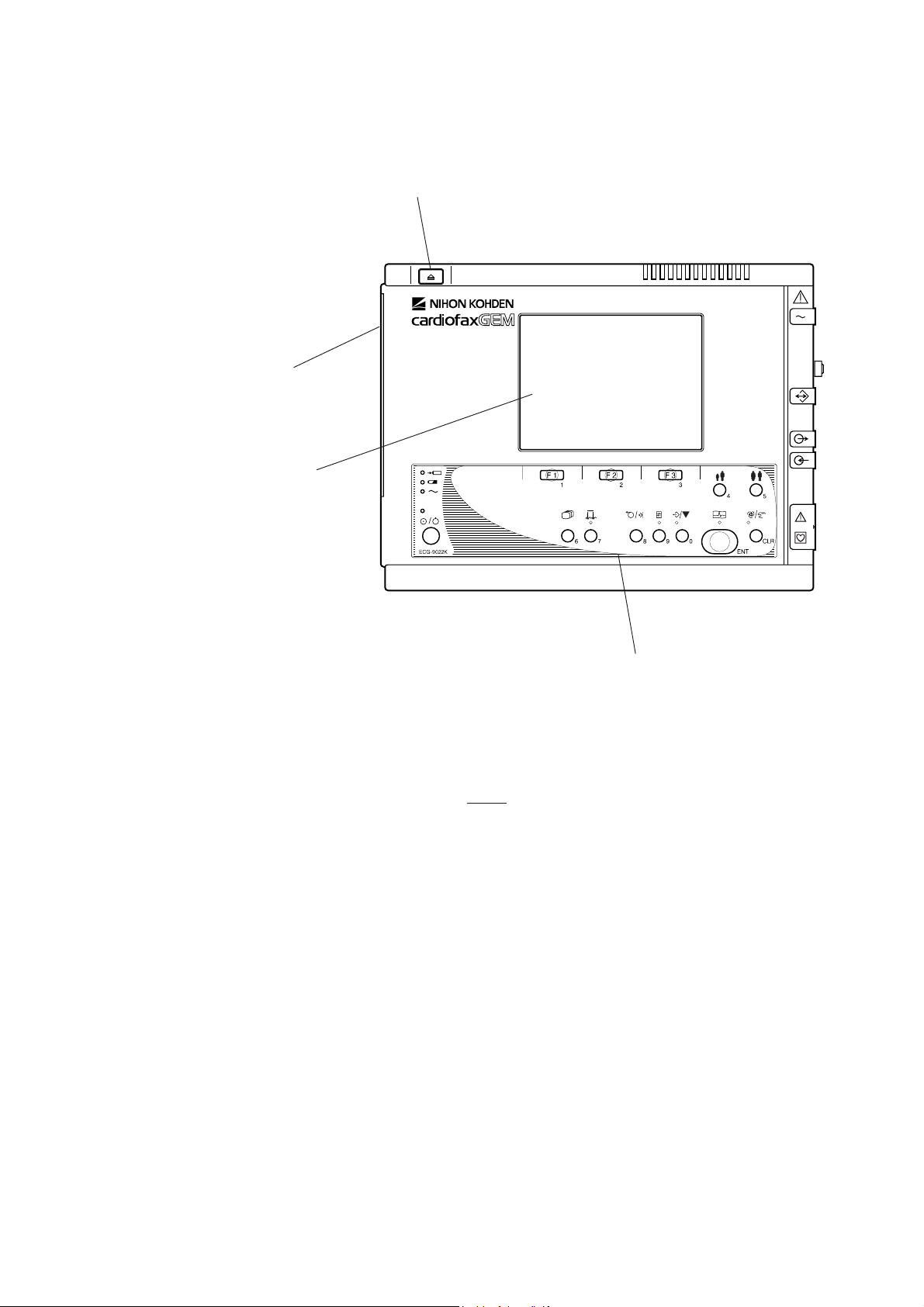
ECG-9020K/P Electrocardiograph
Top View
3
2
4
1
Name
1. Operation panel
2. Magazine (recording paper container)
3. Magazine release button
4. LCD screen
The keyswithes on the ECG-9020P have a name label instead of the symbol.
1.8 Service Manual ECG-9010/9020 Rev B

Operation Panel
1. GENERAL
16
5
6
7
8
9
Name
5. Battery charge lamp
6. Battery operation lamp
7. AC power lamp
8. POWER key/lamp
9. MODE key
10 RHYTHM key/lamp
11. FEED/MARK key
12. FILTER key/lamp
13. COPY/CAL key/lamp
14. START/STOP key/lamp
15. AUTO/MANUAL key/lamp
16. F1, F2, F3 function keys
17. AGE key
18. SEX key
10
11
12
17
13
18
14
15
Service Manual ECG-9010/9020 Rev B 1.9
1. GENERAL
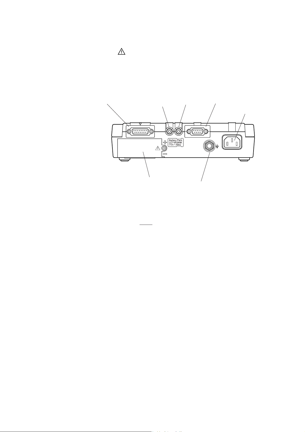
Right Side Panel
For the mark, refer to the descriptions for the Right Side Panel in Section 1
“Panel Descriptions” of the ECG-9020K or ECG 9020P Operator’s Manual.
19
20
24
Name
19. Patient input connector
20. EXT-IN connector
21. CRO-OUT
22. SIO connector
23. AC power cord socket
24. Battery compartment
25. Equipotential ground terminal
21
25
22
23
1.10 Service Manual ECG-9010/9020 Rev B
1. GENERAL
ECG-9022K Electrocardiograph
Top View
3
2
4
1
Name
1. Operation panel
2. Magazine (recording paper container)
3. Magazine release button
4. LCD screen
Service Manual ECG-9010/9020 Rev B 1.11
1. GENERAL
Operation Panel
16
5
6
7
8
9
Name
5. Battery charge lamp
6. Battery operation lamp
7. AC power lamp
8. POWER key/lamp
9. MODE key
10 RHYTHM key/lamp
11. FEED/MARK key
12. FILTER key/lamp
13. COPY/CAL key/lamp
14. START/STOP key/lamp
15. AUTO/MANUAL key/lamp
16. F1, F2, F3 function keys
17. AGE key
18. SEX key
10
11
12
17
13
18
14
15
1.12 Service Manual ECG-9010/9020 Rev B

1. GENERAL
Right Side Panel
For the mark, refer to the descriptions for the Right Side Panel in Section 1
“Panel Descriptions” of the ECG-9022K Operator’s Manual.
19
20
24
Name
19. Patient input connector
20. EXT-IN connector
21. CRO-OUT
22. SIO connector
23. AC power cord socket
24. Battery compartment
25. Equipotential ground terminal
21
25
22
23
Service Manual ECG-9010/9020 Rev B 1.13
1. GENERAL
Composition
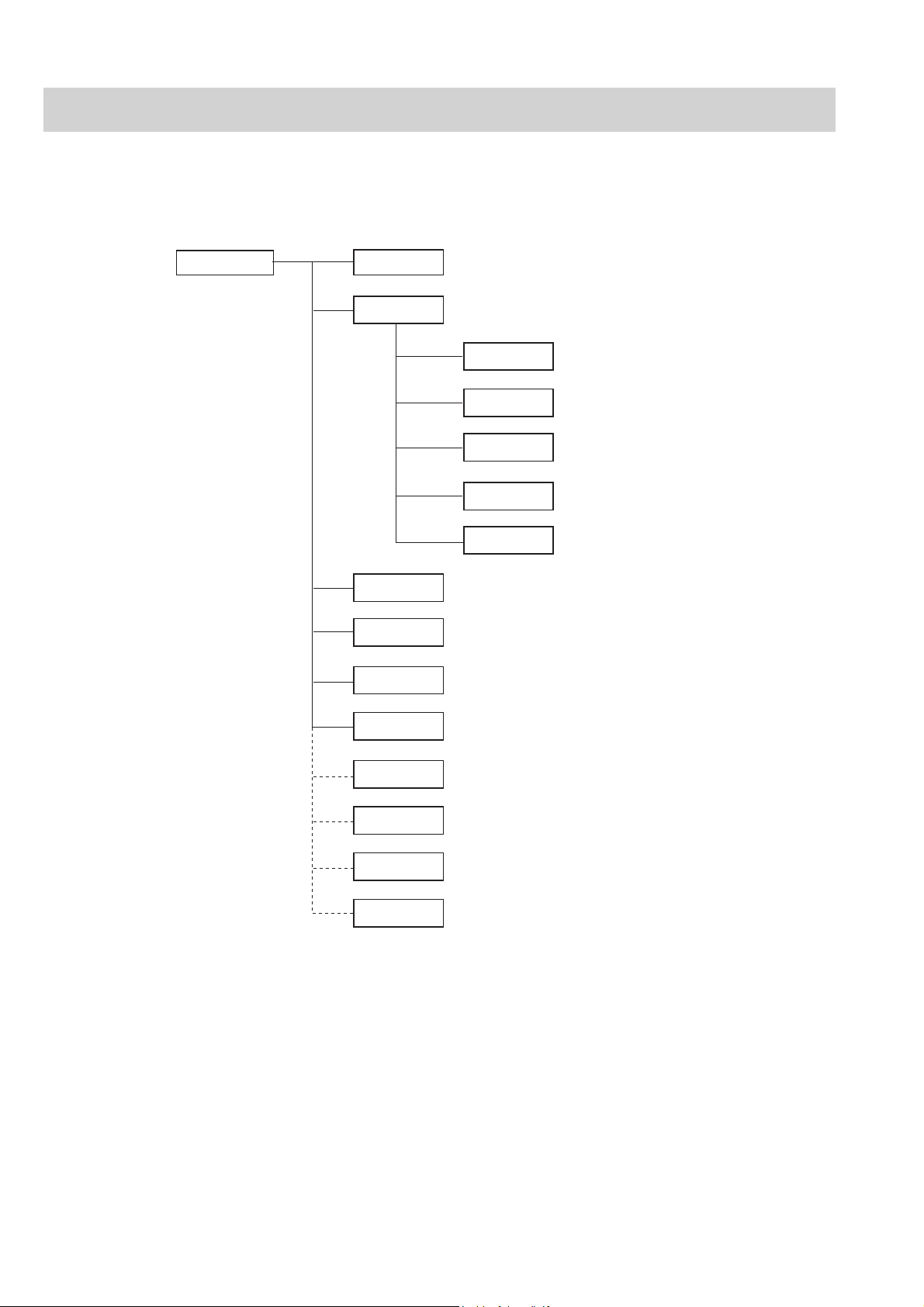
ECG-9010K Electrocardiograph
ECG-9010K
RK-0002 Bottom Casing Assy
RK-0003 Internal Parts
GC-0011 Motor Assy
RH-0001 Magazine Assy
RK-0004 Thermal Head Assy
RK-0005 Speaker Assy
RK-0006 Battom Terminal Assy
RK-0007 ECG-9010K Top Casing Assy
SC-903D Power Unit
UT-23561 ECG Control Board
(Optional)
UT-2357 Flash ROM Board
KD-104E Cart
KH-801E Patinet Cable Hanger
DI-106D Fixing Plate for Cart
YC-901D Carrying Case
• To order a replacement assembly above, use the Code No.
• To order a replacement component inside an assembly, refer to “Section 7
Replaceablet Parts List”.
1.14 Service Manual ECG-9010/9020 Rev B

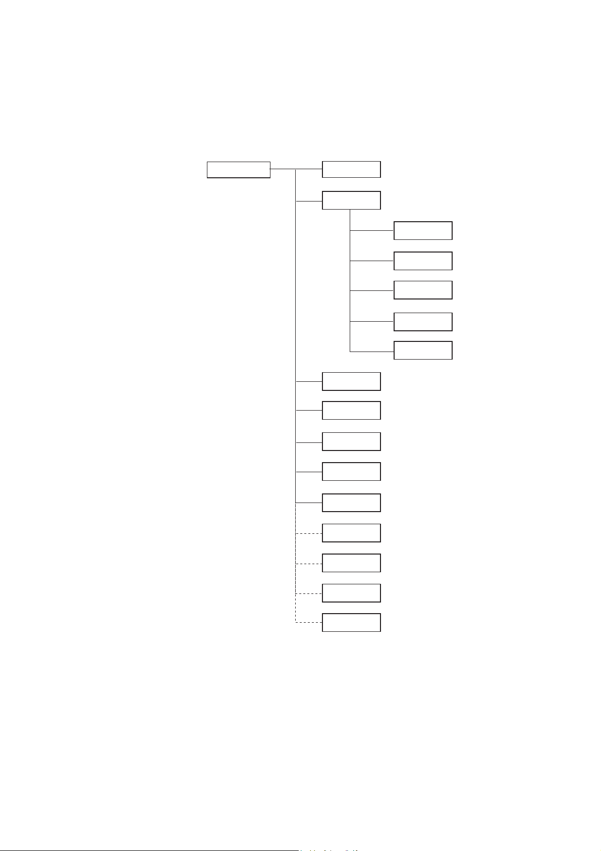
ECG-9020K Electrocardiograph
ECG-9020K
(Optional)
RK-0002 Bottom Casing Assy
RK-0003 Internal Parts
GC-0011 Motor Assy
RH-0001 Magazine Assy
RK-0004 Thermal Head Assy
RK-0005 Speaker Assy
RK-0006 Battom Terminal Assy
RK-0009 ECG-9020K Top Casing Assy
SC-903D Power Unit
UT-23561 ECG Control Board
UT-2357 Flash ROM Board
VL-0001 LCD Assy
KD-104E Cart
KH-801E Patinet Cable Hanger
DI-106D Fixing Plate for Cart
YC-901D Carrying Case
1. GENERAL
Service Manual ECG-9010/9020 Rev B 1.15
• To order a replacement assembly above, use the Code No.
• To order a replacement component inside an assembly, refer to “Section 7
Replaceablet Parts List”.

1. GENERAL
ECG-9020P
(Optional)
RK-0002 Bottom Casing Assy
RK-0003 Internal Parts
GC-0011 Motor Assy
RH-0001 Magazine Assy
RK-0004 Thermal Head Assy
RK-0005 Speaker Assy
RK-0006 Battom Terminal Assy
RK-0044 ECG-9020P Top Casing Assy
SC-903D Power Unit
UT-23563 ECG Control Board
UT-23577 Flash ROM Board
VL-0001 LCD Assy
KD-104E Cart
KH-801E Patinet Cable Hanger
DI-106D Fixing Plate for Cart
YC-901D Carrying Case
ECG-9020P Electrocardiograph
1.16 Service Manual ECG-9010/9020 Rev B
• To order a replacement assembly above, use the Code No.
• To order a replacement component inside an assembly, refer to “Section 7
Replaceablet Parts List”.
ECG-9022K Electrocardiograph
ECG-9022K
(Optional)
RK-0002 Bottom Casing Assy
RK-0003 Internal Parts
GC-0011 Motor Assy
RH-0001 Magazine Assy
RK-0004 Thermal Head Assy
RK-0005 Speaker Assy
RK-0006 Battom Terminal Assy
RK-0058 ECG-9022K Top Casing Assy
SC-903D Power Unit
UT-23564 ECG Control Board
UT-2357D Flash ROM Board
VL-0001 LCD Assy
KD-104E Cart
KH-801E Patinet Cable Hanger
DI-106D Fixing Plate for Cart
YC-901D Carrying Case
1. GENERAL
Service Manual ECG-9010/9020 Rev B 1.17
• To order a replacement assembly above, use the Code No.
• To order a replacement component inside an assembly, refer to “Section 7
Replaceablet Parts List”.
1. GENERAL
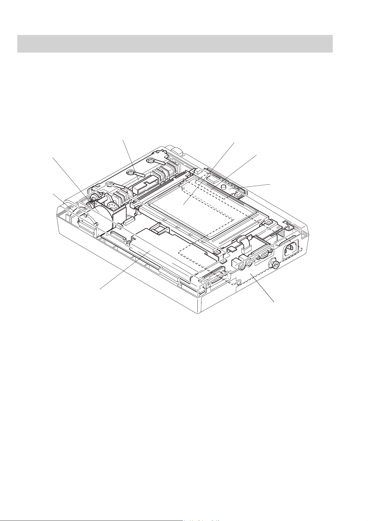
Location
Motor Assy
Speaker Assy
ECG Control Board
Thermal Head Assy
LCD Assy (for ECG-9020K/9020P/9022K only)
Flash ROM Board
Inverter Board
(for ECG-9020K/9020P/9022K only)
Power Unit
1.18 Service Manual ECG-9010/9020 Rev B
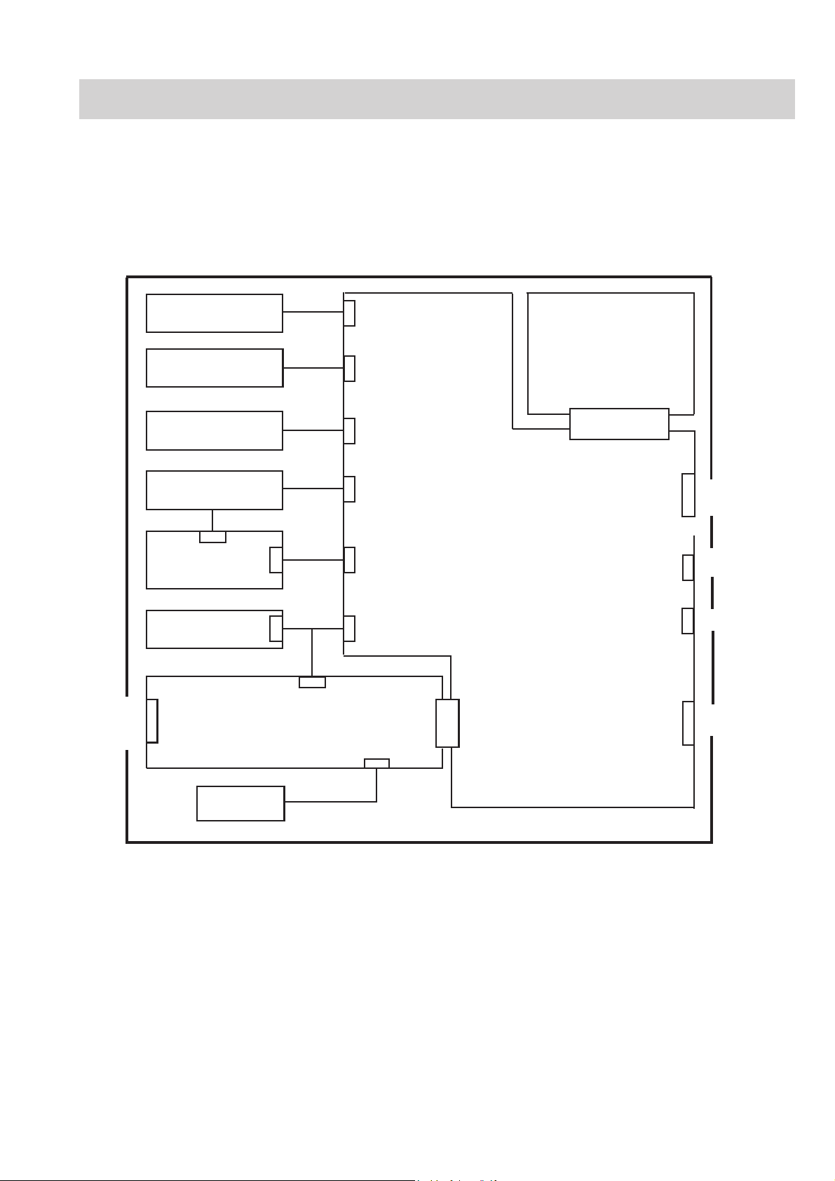
Block Diagram
1. GENERAL
NOTE
The LCD module and inverter board are used for the ECG-9020K,
ECG-9020P and ECG-9022K only.
AC
source
Piezo-electric
buzzer
Motor, Motor sensor,
Mark sensor
Membrane key
LCD module
2 pin
5 pin
Inverter board
Thermal head
CN11 (3pin)
Power Unit
CNA011
CNA012
CNA015
CNA013
CN31 (16pin)
CNJ032 (2pin)
CNJ036 (12pin)
CNJ033 (40pin)
CNJ012 (12pin)
CNJ013 (6pin)
CNJ011 (12pin)
CN021
(30pin)
CN51 (4pin)
Flash ROM Board
ECG Control Board
CNJ035 (30pin)
CNJ011 (80pin)
CNJ021 (80pin)
CNJ031 (D-SUB 9pin)
CNJ043 (mini jack)
CNJ041 (mini jack)
CNJ091 (D-SUB15pin)
SIO
EXT-IN
CRO
Patient Input
Battery
CNA014
Service Manual ECG-9010/9020 Rev B 1.19
1. GENERAL
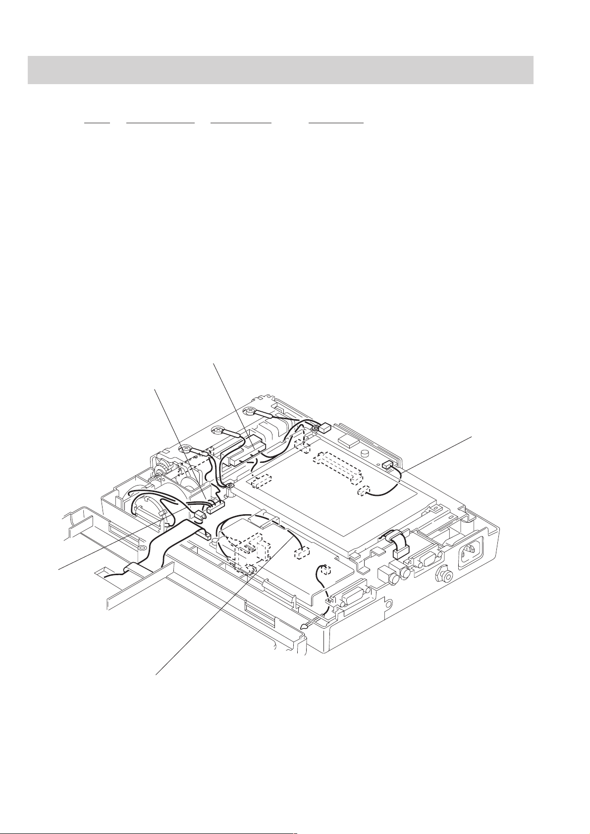
Connection Diagram
Index Connector No. NK Code No. Description
1* CNA011 543993A ZHR-2 speaker cable (L50)
2 CNA012 544002A ZHR-12 motor cable (L120, 65)
3 CNA013 544029B FCN723/DF11(100)/51021(40)
4 CNA014 544011A EHR-4 battery terminal cable (L150)
5 CNA015 544038A 51021-0500/51021-0600 (L50)
* We cannot provide this cable seperately; we can only provide it as part of a complete Speaker assy. Refer to
“Speaker Assy” in Section 8.
①CNA011
③CNA013
②CNA012
⑤CNA015
④CNA014
1.20 Service Manual ECG-9010/9020 Rev B

Section 2 Maintenance
Replacement...................................................................................................................... 2.1
Periodic Replacement Schedule.............................................................................. 2.1
Cleaning............................................................................................................................. 2.2
Cleaning and Greasing Schedules .......................................................................... 2.2
Cleaning the Paper Mark Sensor and Paper Empty Sensor .................................... 2.2
Cleaning the Motor Rotation Sensor and
Greasing the Motor Gear and Gear Meshed with Motor Gear................................. 2.3
Service Manual ECG-9010/9020 Rev A 2C.1
 Loading...