


 Loading...
ECG-9620L ECG-9620M ECG-9620N ECG-9620P ECG-9620S ECG-9620T ECG-9620U
SERVICE MANUAL
cardiofax
ELECTROCARDIOGRAPH
ECG-9620
08CK2.782.00516E
|
|
CONTENTS |
|
Contents |
|
|
GENERAL HANDLING PRECAUTIONS ................................................................................. |
i |
|
WARRANTY POLICY ............................................................................................................. |
ii |
|
EMC RELATED CAUTION ..................................................................................................... |
iii |
|
Conventions Used in this Manual and Instrument .................................................................. |
iv |
|
Dangers, Warnings, Cautions and Notes ..................................................................... |
iv |
|
Explanations of the Symbols in this Manual and Instrument ........................................ |
v |
Section 1 |
General ................................................................................... |
1C.1 |
|
Introduction ......................................................................................................................... |
1.1 |
|
General Information on Servicing ....................................................................................... |
1.2 |
|
Service Policy, Service Parts and Patient Safety Checks ................................................... |
1.4 |
|
Service Policy ........................................................................................................... |
1.4 |
|
Service Parts ............................................................................................................ |
1.4 |
|
Patient Safety Checks ............................................................................................... |
1.5 |
|
Maintenance Equipments and Tools ......................................................................... |
1.5 |
|
General Safety Information ................................................................................................. |
1.6 |
|
Specifications .................................................................................................................... |
1.11 |
|
Panel Descriptions ............................................................................................................ |
1.14 |
|
Front Panel ............................................................................................................. |
1.14 |
|
Left Side Panel ........................................................................................................ |
1.14 |
|
Operation Panel ...................................................................................................... |
1.15 |
|
Right Side Panel ..................................................................................................... |
1.15 |
|
Rear Panel .............................................................................................................. |
1.16 |
|
Composition ...................................................................................................................... |
1.17 |
|
Standard Components ............................................................................................ |
1.17 |
|
Options ................................................................................................................... |
1.17 |
|
Location ............................................................................................................................ |
1.18 |
Section 2 |
Maintenance ........................................................................... |
2C.1 |
|
Replacement ....................................................................................................................... |
2.1 |
|
Periodic Replacement Schedule ............................................................................... |
2.1 |
|
Cleaning and Lubrication .................................................................................................... |
2.2 |
|
Cleaning and Greasing Schedules ........................................................................... |
2.2 |
|
Cleaning the Paper Mark Sensor and Paper Empty Sensor ..................................... |
2.2 |
|
Cleaning the Motor Rotation Sensor and Lubricating the Motor Gear and Gear |
|
|
Meshed with Motor Gear .......................................................................................... |
2.3 |
|
Maintenance Check Sheet .................................................................................................. |
2.5 |
Section 3 |
Troubleshooting and System Error Message ...................... |
3C.1 |
|
Troubleshooting Flowchart .................................................................................................. |
3.1 |
|
Troubleshooting Table ......................................................................................................... |
3.4 |
|
Troubleshooting General Operation Problem ............................................................ |
3.4 |
Service Manual ECG-9620 |
C.1 |
CONTENTS |
|
Troubleshooting Recording Problem ......................................................................... |
3.6 |
System Error Message ....................................................................................................... |
3.7 |
Section 4 |
System Test, Adjustment and Setting .................................. |
4C.1 |
|
System Test ........................................................................................................................ |
4.1 |
|
Overall ...................................................................................................................... |
4.1 |
|
Calling up the System Test Level 1 ........................................................................... |
4.2 |
|
Calling up the System Test Level 2 ........................................................................... |
4.3 |
|
Entering the System Test Number ............................................................................ |
4.4 |
|
Executing the System Test ........................................................................................ |
4.5 |
|
Quitting the System Test ........................................................................................... |
4.6 |
|
Exiting the System Test Mode ................................................................................... |
4.6 |
|
Demonstration .................................................................................................................... |
4.7 |
|
Recorder ............................................................................................................................. |
4.8 |
|
Thermal Head ................................................................................................................... |
4.10 |
|
Key .................................................................................................................................... |
4.11 |
|
Memory ............................................................................................................................. |
4.12 |
|
Single Memory Test Mode ...................................................................................... |
4.13 |
|
Continuous Memory Test Mode .............................................................................. |
4.13 |
|
LCD/LED ........................................................................................................................... |
4.14 |
|
Input Unit .......................................................................................................................... |
4.16 |
|
Calibration ......................................................................................................................... |
4.17 |
|
Communication ................................................................................................................. |
4.18 |
|
CRO/EXT1 ........................................................................................................................ |
4.20 |
|
System Setup Initialization ................................................................................................ |
4.22 |
|
ECG Findings List Recording ............................................................................................ |
4.23 |
|
Recording Resolution Setting ........................................................................................... |
4.24 |
|
Date and Time Setting ...................................................................................................... |
4.25 |
|
Setting the Date and Time ...................................................................................... |
4.25 |
Section 5 |
Board/Unit Description .......................................................... |
5C.1 |
|
Block Diagram ..................................................................................................................... |
5.1 |
|
Power Unit .......................................................................................................................... |
5.2 |
|
ECG Control Board ............................................................................................................. |
5.2 |
Section 6 |
Disassembly ........................................................................... |
6C.1 |
|
Before You Begin ................................................................................................................. |
6.1 |
|
Warnings and Cautions ............................................................................................ |
6.1 |
|
Required Tools .......................................................................................................... |
6.1 |
|
Cable Connection ............................................................................................................... |
6.2 |
|
Removing the Upper Casing ............................................................................................... |
6.4 |
|
Removing the Magazine and Recording Paper ........................................................ |
6.4 |
|
Removing the Battery Pack ...................................................................................... |
6.4 |
|
Removing the Upper Casing ..................................................................................... |
6.4 |
|
Removing the Thermal Head and Motor Assy .................................................................... |
6.5 |
|
Removing the Thermal Head .................................................................................... |
6.5 |
C.2 |
Service Manual ECG-9620 |
|
|
CONTENTS |
|
Removing the Motor Assy ......................................................................................... |
6.6 |
|
Removing the ECG Control Board ...................................................................................... |
6.6 |
|
Removing the Power Board ................................................................................................ |
6.8 |
|
Removing the Power Board ...................................................................................... |
6.8 |
|
Replacing the Power Fuse and Battery Fuse ........................................................... |
6.9 |
|
Removing the Key Board and LCD Unit ............................................................................ |
6.10 |
Section 7 |
Replaceable Parts List ........................................................... |
7C.1 |
|
Instrument ........................................................................................................................... |
7.2 |
Section 8 |
Connector Pin Assignment ..................................................... |
8.1 |
|
Attaching the Ferrite Core ......................................................................................... |
8.1 |
|
EXT-IN Connector ..................................................................................................... |
8.2 |
|
CRO-OUT Connector ............................................................................................... |
8.2 |
|
SIO Connector .......................................................................................................... |
8.2 |
Service Manual ECG-9620 |
C.3 |
GENERAL HANDLING PRECAUTIONS
This device is intended for use only by qualified medical personnel.
Use only Nihon Kohden approved products with this device. Use of non-approved products or in a non-approved manner may affect the performance specifications of the device. This includes, but is not limited to, batteries, recording paper, pens, extension cables, electrode leads, input boxes and AC power.
Please read these precautions thoroughly before attempting to operate the instrument.
1.To safely and effectively use the instrument, its operation must be fully understood.
2.When installing or storing the instrument, take the following precautions:
(1)Avoid moisture or contact with water, dust, extreme atmospheric pressure, excessive humidity and temperatures, poorly ventilated areas, and saline or sulphuric air.
(2)Place the instrument on an even, level floor. Avoid vibration and mechanical shock, even during transport.
(3)Avoid placing in an area where chemicals are stored or where there is danger of gas leakage.
(4)The power line source to be applied to the instrument must correspond in frequency and voltage to product specifications, and have sufficient current capacity.
(5)Choose a room where a proper grounding facility is available.
3.Before Operation
(1)Check that the instrument is in perfect operating order.
(2)Check that the instrument is grounded properly.
(3)Check that all cords are connected properly.
(4)Pay extra attention when the instrument is in combination with other instruments to avoid misdiagnosis or other problems.
(5)All circuitry used for direct patient connection must be doubly checked.
(6)Check that battery level is acceptable and battery condition is good when using battery-operated models.
4.During Operation
(1)Both the instrument and the patient must receive continual, careful attention.
(2)Turn power off or remove electrodes and/or transducers when necessary to assure the patient’s safety.
(3)Avoid direct contact between the instrument housing and the patient.
5.To Shutdown After Use
(1)Turn power off with all controls returned to their original positions.
(2)Remove the cords gently; do not use force to remove them.
(3)Clean the instrument together with all accessories for their next use.
6.The instrument must receive expert, professional attention for maintenance and repairs. When the instrument is not functioning properly, it should be clearly marked to avoid operation while it is out of order.
7.The instrument must not be altered or modified in any way.
8.Maintenance and Inspection:
(1)The instrument and parts must undergo regular maintenance inspection at least every 6 months.
(2)If stored for extended periods without being used, make sure prior to operation that the instrument is in perfect operating condition.
Service Manual ECG-9620 |
i |
(3)Technical information such as parts list, descriptions, calibration instructions or other information is available for qualified user technical personnel upon request from your Nihon Kohden distributor.
9.When the instrument is used with an electrosurgical instrument, pay careful attention to the application and/or location of electrodes and/or transducers to avoid possible burn to the patient.
10.When the instrument is used with a defibrillator, make sure that the instrument is protected against defibrillator discharge. If not, remove patient cables and/or transducers from the instrument to avoid possible damage.
WARRANTY POLICY
Nihon Kohden Corporation (NKC) shall warrant its products against all defects in materials and workmanship for one year from the date of delivery. However, consumable materials such as recording paper, ink, stylus and battery are excluded from the warranty.
NKC or its authorized agents will repair or replace any products which prove to be defective during the warranty period, provided these products are used as prescribed by the operating instructions given in the operator’s and service manuals.
No other party is authorized to make any warranty or assume liability for NKC’s products. NKC will not recognize any other warranty, either implied or in writing. In addition, service, technical modification or any other product change performed by someone other than NKC or its authorized agents without prior consent of NKC may be cause for voiding this warranty.
Defective products or parts must be returned to NKC or its authorized agents, along with an explanation of the failure. Shipping costs must be pre-paid.
This warranty does not apply to products that have been modified, disassembled, reinstalled or repaired without Nihon Kohden approval or which have been subjected to neglect or accident, damage due to accident, fire, lightning, vandalism, water or other casualty, improper installation or application, or on which the original identification marks have been removed.
ii |
Service Manual ECG-9620 |

EMC RELATED CAUTION
This equipment and/or system complies with the International Standard IEC60601-1-2 for electromagnetic compatibility for medical electrical equipment and/or system. However, an electromagnetic environment that exceeds the limits or levels stipulated in the IEC60601-1-2, can cause harmful interference to the equipment and/or system or cause the equipment and/or system to fail to perform its intended function or degrade its intended performance. Therefore, during the operation of the equipment and/or system, if there is any undesired deviation from its intended operational performance, you must avoid, identify and resolve the adverse electromagnetic effect before continuing to use the equipment and/or system.
The following describes some common interference sources and remedial actions:
1.Strong electromagnetic interference from a nearby emitter source such as an authorized radio station or cellular phone:
Install the equipment and/or system at another location if it is interfered with by an emitter source such as an authorized radio station. Keep the emitter source such as cellular phone away from the equipment and/or system.
2.Radio-frequency interference from other equipment through the AC power supply of the equipment and/or system:
Identify the cause of this interference and if possible remove this interference source. If this is not possible, use a different power supply.
3.Effect of direct or indirect electrostatic discharge:
Make sure all users and patients in contact with the equipment and/or system are free from direct or indirect electrostatic energy before using it.
4.Electromagnetic interference with any radio wave receiver such as radio or television:
If the equipment and/or system interferes with any radio wave receiver, locate the equipment and/or system as far as possible from the radio wave receiver.
If the above suggested remedial actions do not solve the problem, consult your Nihon Kohden Corporation subsidiary or distributor for additional suggestions.
The CE mark is a protected conformity mark of the European Community. The products herewith comply with the requirements of the Medical Device Directive 93/42/EEC.
The CE mark is applied only to the ECG-9620L/M/N Electrocardiograph.
This equipment complies with EUROPEAN STANDARD EN-60601-1-2 (1993) which requires EN-55011, class B.
Service Manual ECG-9620 |
iii |
Conventions Used in this Manual and Instrument
Dangers, Warnings, Cautions and Notes
Warnings, cautions and notes are used in this manual to alert or signal the reader to specific information.
DANGER
A danger is used to alert the user to a hazardous situation which will cause death or serious injury.
WARNING
A warning alerts the user to possible injury or death associated with the use or misuse of the instrument.
CAUTION
A caution alerts the user to possible injury or problems with the instrument associated with its use or misuse such as instrument malfunction, instrument failure, damage to the instrument, or damage to other property.
NOTE
A note provides specific information, in the form of recommendations, prerequirements, alternative methods or supplemental information.
iv |
Service Manual ECG-9620 |
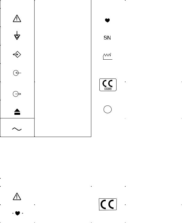
Explanations of the Symbols in this Manual and Instrument
The following symbols found in this manual/instrument bear the respective descriptions as given.
Cardiograph
Symbol |
Description |
Symbol |
Description |
|||||||||||
|
|
|
|
|
|
|
|
|
|
|
|
|
|
|
|
Attention, consult operator’s |
|
|
|
|
|
|
|
|
|
|
|
|
Type CF applied part |
|
manual |
|
|
|
|
|
|
|
|
|
|
|
|
|
|
|
|
|
|
|
|
|
|
|
|
|
|
|
|
|
|
|
|
|
|
|
|
|
|
|
|
|
|
|
|
|
|
|
|
|
|
|
|
|
|
|
|
|
|
|
Equipotential terminal |
|
|
|
|
|
|
|
|
|
|
|
|
Serial number |
|
|
|
|
|
|
|
|
|
|
|
|
|
||
|
|
|
|
|
|
|
|
|
|
|
|
|
|
|
|
|
|
|
|
|
|
|
|
|
|
|
|
|
|
|
Serial input/output terminal |
|
|
|
|
|
|
|
|
|
|
|
|
Date of manufacture |
|
|
|
|
|
|
|
|
|
|
|
|
|
||
|
|
|
|
|
|
|
|
|
|
|
|
|
|
|
|
|
|
|
|
|
|
|
|
|
|
|
|
|
|
|
Input terminal for analog signal |
|
|
|
|
|
|
|
|
|
|
|
|
The CE mark is a protected |
|
|
|
|
|
|
|
|
|
|
|
|
|
conformity mark of European |
|
|
|
|
|
|
|
|
|
|
|
|
|
|
|
|
|
|
|
|
|
|
|
|
|
|
|
|
|
|
Community. The products |
|
Output terminal for analog |
|
|
|
|
|
|
|
|
|
|
|
|
herewith comply with the |
|
|
|
|
|
|
|
|
|
|
|
|
|
||
|
|
|
|
|
|
|
|
|
|
|
|
|
requirements of the Medical |
|
|
signal |
|
|
|
|
|
|
|
|
|
|
|
|
Device Directive 93/42/EEC. |
|
|
|
|
|
|
|
|
|
|
|
|
|
|
|
|
Eject (magazine release button) |
|
|
|
|
|
|
|
|
|
|
|
|
Protective earth |
|
|
|
|
|
|
|
|
|
|
|
|
|
||
|
|
|
|
|
|
|
|
|
|
|
|
|
||
|
|
|
|
|
|
|
|
|
|
|
|
|
|
|
|
|
|
|
|
|
|
|
|
|
|
|
|
|
|
Alternative current
The CE mark is applied only to the
ECG-9620L/M/N Electrocardiograph.
Patient cable
Symbol |
Description |
Symbol |
Description |
||||||
|
|
|
|
|
|
|
|
|
|
|
|
|
|
|
Attention, consult operator’s |
|
|
|
The CE mark is a protected |
|
|
|
|
|
manual |
|
|
|
conformity mark of European |
|
|
|
|
|
|
|
|
|
Community. The products |
|
|
|
|
|
Defibrillation-proof |
|
|
|
herewith comply with the |
|
|
|
|
|
|
|
|
requirements of the Medical |
|
|
|
|
|
|
|
|
|
||
|
|
|
|
|
Type CF applied par |
|
|
|
Device Directive 93/42/EEC. |
|
|
|
|
|
|
|
|
||
|
|
|
|
|
|
|
|
|
|
Service Manual ECG-9620 |
v |
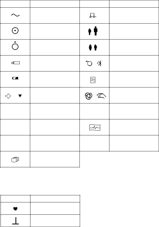
Operation panel
Symbol |
Description |
Symbol |
Description |
|
Alternating current |
|
Rhythm |
|
|
|
5 |
|
“On” only for a part of |
|
Age |
|
equipment |
|
|
|
|
6 |
|
|
|
|
|
|
“Off” only for a part of |
|
Sex |
|
equipment |
|
|
|
|
7 |
|
|
|
|
|
|
Battery charging |
/ |
Paper feed / Mark |
|
|
||
|
|
|
8 |
|
Battery check |
|
Filter |
|
|
|
9 |
/ |
Copy / Calibration |
/ |
Automatic / Manual control |
|
0 |
|
|
F1 |
F1 function key |
CLR |
Clear |
|
1 |
|
|
F2 |
F2 function key |
|
Start/Stop recording |
|
2 |
|
|
F3 |
F3 function key |
ENT |
Enter |
|
3 |
|
|
Mode
4
A key with a numeric number is used to enter numbers in the System Setup screen and paient information.
On screen
Symbol |
Description |
QRS sync mark
CAL mark
vi |
Service Manual ECG-9620 |
Section 1 General
Introduction ........................................................................................................................ |
1.1 |
General Information on Servicing ...................................................................................... |
1.2 |
Service Policy, Service Parts and Patient Safety Checks .................................................. |
1.4 |
Service Policy .......................................................................................................... |
1.4 |
Service Parts ........................................................................................................... |
1.4 |
Patient Safety Checks .............................................................................................. |
1.5 |
Maintenance Equipments and Tools ........................................................................ |
1.5 |
General Safety Information ................................................................................................ |
1.6 |
Specifications ................................................................................................................... |
1.11 |
Panel Descriptions ........................................................................................................... |
1.14 |
Front Panel ............................................................................................................ |
1.14 |
Left Side Panel ....................................................................................................... |
1.14 |
Operation Panel ..................................................................................................... |
1.15 |
Right Side Panel .................................................................................................... |
1.15 |
Rear Panel ............................................................................................................. |
1.16 |
Composition ..................................................................................................................... |
1.17 |
Standard Components ........................................................................................... |
1.17 |
Options .................................................................................................................. |
1.17 |
Location ........................................................................................................................... |
1.18 |
Service Manual ECG-9620 |
1C.1 |

1. GENERAL
Introduction
This service manual provides useful information to qualified service personnel to understand, troubleshoot, service, maintain and repair the ECG-9620L/M/N/P/S/T/ U Electrocardiograph (referred to as “the instrument” in this service manual).
The System test, Adjustment and Setting section in this service manual describes the maintenance that should be performed by qualified service personnel. The Maintenance section in the operator’s manual describes the maintenance that can be performed by the user.
The information in the operator’s manual is primarily for the user. However, it is important for service personnel to thoroughly read the operator’s manual and service manual before starting to troubleshoot, service, maintain or repair this instrument. This is because service personnel need to understand the operation of the instrument in order to effectively use the information in the service manual.
Service Manual ECG-9620 |
1.1 |

1. GENERAL
General Information on Servicing
Note the following information when servicing the instrument.
CAUTIONS
Safety
•There is the possibility that the outside surface of the instrument, such as the operation keys, could be contaminated by contagious germs, so disinfect and clean the instrument before servicing it.
When servicing the instrument, wear rubber gloves to protect yourself from infection.
•There is the possibility that when the lithium battery is broken, a solvent inside the lithium battery could flow out or a toxic substance inside it could come out. If the solvent or toxic substance touches your skin or gets into your eye or mouth, immediately wash it with a lot of water and see a physician.
Liquid ingress
The instrument is not waterproof, so do not install the instrument where water or liquid can get into or fall on the instrument. If liquid accidentally gets into the instrument or the instrument accidentally drops into liquid, disassemble the instrument, clean it with clean water and dry it completely. After reassembling, verify that there is nothing wrong with the patient safety checks and function/ performance checks. If there is something wrong with the instrument, contact your Nihon Kohden representative for repair.
Environmental Safeguards
Depending on the local laws in your community, it may be illegal to dispose of the lithium battery in the regular waste collection. Check with your local officials for proper disposal procedures.
Disinfection and cleaning
To disinfect the outside surface of the instrument, wipe it with a nonabrasive cloth moistened with alcohol. Do not use any other disinfectants or ultraviolet rays to disinfect the instrument.
1.2 |
Service Manual ECG-9620 |

1. GENERAL
Caution - continued
Transport
•Use the specified shipment container and packing material to transport the instrument. If necessary, double pack the instrument. Also, put the instrument into the shipment container after packing so that the buffer material does not get inside the instrument.
•When transporting a board or unit of the instrument, be sure to put it in a conductive bag. Never use an aluminum bag to transport a board or unit. Also, never use a styrene foam or plastic bag which generates static electricity to wrap the board or unit of the instrument.
Handling the instrument
•Because the outside surface of the instrument is made of resin, the outside surface of the instrument is easily damaged. So when handling the instrument, remove clutter from around the instrument and be careful to not damage the instrument or get it dirty.
•Because most of the boards in the instrument are multilayer boards with surface mount electrical devices (SMD), a special tool is required to remove and solder the electrical devices on it. To avoid damaging other electrical components, do not remove and solder SMD components yourself.
Measuring and Test Equipment
Maintain the accuracy of the measuring and test equipment by checking and calibrating it according to the check and calibration procedures.
Service Manual ECG-9620 |
1.3 |

1. GENERAL
Service Policy, Service Parts and Patient Safety Checks
Service Policy
Our technical service policy for this instrument is to replace the faulty unit, board or part or damaged mechanical part with a new one. Do not perform electrical device or component level repair of the multilayer board or unit. We do not support component level repair outside the factory for the following reasons:
•Most of the boards are multilayer boards with surface mount electrical devices, so the mounting density of the board is too high.
•A special tool or high degree of repair skill is required to repair the multilayer boards with surface mount electrical devices.
Only disassemble the instrument or replace a board or unit in an environment where the instrument is protected against static electricity.
|
Refer to “Replaceable Parts List” of this manual for the service parts for technical |
|
service that we provide. |
Service Parts |
NOTE |
|
When ordering parts or accessories from your Nihon Kohden |
|
representative, please quote the NK code number and part name |
|
which is listed in this service manual, and the name or model of the |
|
unit in which the required part is located. This will help us to |
|
promptly attend to your needs. Always use parts and accessories |
|
recommended or supplied by Nihon Kohden Corporation to assure |
|
maximum performance from your instrument. |
1.4 |
Service Manual ECG-9620 |
Patient Safety Checks
Maintenance Equipments
and Tools
1. GENERAL
Periodic maintenance procedures and diagnostic check procedures are provided in this manual to ensure that the instrument is operating in accordance with its design and production specifications. To verify that the instrument is working in a safe manner with regard to patient safety, patient safety checks should be performed on the instrument before it is first installed, periodically after installation, and after any repair is made on the instrument.
For patient safety checks, perform the following checks as described in the IEC60601-1 “Medical electrical equipment - Part 1: General requirements for safety”:
•Protective earth resistance check
•Earth leakage current check
•Enclosure leakage current check
•Patient leakage current check
•Withstanding voltage check
Test equipment
When repairing or calibrating the instrument, the following test equipment is required.
•Oscilloscope: 2 channels or more for input signal, 50 mV to 5 V input range, 1/ 10 attenuating probe and 100 MHz or more frequency response characteristic must be provided.
•Digital voltmeter: standard type (An oscilloscope can be used instead of the digital voltmeter.)
Service Manual ECG-9620 |
1.5 |
1. GENERAL
General Safety Information
DANGER
•Never use this cardiograph in the presence of any flammable anesthetic gas or high-concentration oxygen atmosphere. Failure to follow this warning may cause explosion or fire.
•Never use this cardiograph in a high-pressure oxygen medical tank. Failure to follow this warning may cause explosion or fire.
WARNING
Using with an electrical surgical unit (ESU)
•Never use this cardiograph near an ESU. The cardiograph may malfunction due to high-frequency noise from the ESU.
•When using this cardiograph with an ESU, refer to the instruction manual for the ESU. Before measurement, check that the return plate is correctly attached to the patient and check that the cardiograph operates correctly when using with the ESU. If the return plate is not attached correctly, it may burn the patient’s skin where the electrodes are attached.
MRI examination
•Do not install this cardiograph in an MRI examination room. The cardiograph may not operate properly due to high-frequency magnetic noise from the MRI.
•When performing MRI tests, remove from the patient all electrodes which are connected to this cardiograph. Failure to follow this warning may cause serious electrical burn on the patient due to local heating caused by dielectric electromotive force. For details, refer to the instruction manual for the MRI.
When performing defibrillation
•Before defibrillation, remove all electrodes and gel from the chest of the patient. If the defibrillator paddle touches electrodes or gel, the discharged energy may burn the patient’s skin.
•Before defibrillation, all persons must keep clear of the bed and must not touch the patient or any equipment connected to the patient. Failure to follow this warning may cause serious electrical burn, shock or other injury.
1.6 |
Service Manual ECG-9620 |

1. GENERAL
Warning - continued
Use only the following specified patient cables when using with a defibrillator or ESU. When the specified patient cable is connected, the cardiograph is type CF defibrillation-proof compliance. Failure to follow this warning will cause serious electrical burn where the electrode is attached and damage the cardiograph due to discharge energy when defibrillation is performed.
Patient cable: BJ-901D – IEC standard, 3 mm diameter tip
BJ-902D – IEC/DIN standard, 4 mm diameter tip
BJ-903D – IEC/DIN standard, clip
BA-901D – AHA requirement, 3 mm diameter tip
BA-903D – AHA requirement, color clip
When using an ESU and defibrillator with the cardiograph, use silver chloride disposable electrodes.
Installation
WARNING
•Only use the 3-prong power cord provided with the cardiograph. Failure to follow this caution may cause electrical shock to the patient and operator.
•Only use the specified patient cable and connect the external instruments with the specified installation procedure. Failure to follow this warning may cause a serious electrical shock to the patient and operator by leakage current.
CAUTION
•When the provided 3-prong power cord cannot be used, operate the cardiograph on battery power. When another type of power cord (especially 2-prong power cord) is used, this may cause electrical shock to the patient and operator.
•When several medical instruments are used together, ground all instruments at the same one-point ground to protect the patient and operator from electrical shock. Any potential difference between instruments may cause electrical shock to the patient and operator.
•When connecting an external instrument to connectors marked with  , the external instrument and this cardiograph must be connected according to the IEC60601-1-1 “Medical electrical equipment - Part 1- 1: General requirements for safety - Collateral standard: Safety requirements for medical electrical systems”. Failure to follow this warning may cause electrical shock to the patient and operator.
•When inserting or removing the battery from the cardiograph, make sure that the cardiograph is turned off. Otherwise, the patient and operator may get an electrical shock.
Service Manual ECG-9620 |
1.7 |

1. GENERAL
Battery Pack
DANGER
•Keep the battery pack away from fire. Do not heat the battery pack. Otherwise, the substance liquid leaks out and the battery pack explodes.
•Never short-circuit the + and – terminals on the battery pack with a wire. Never store or carry the battery pack with metal such as necklace or hair pins. The battery pack short-circuits and a large current flows, causing leakage of the substance liquid inside the battery and battery explosion.
•Never disassemble or modify the battery pack. Never damage or directly solder the sheath tube. The battery pack short-circuits, the substance liquid comes out and the battery pack explodes.
•Do not use a battery pack which is damaged, such as from falling. There is a gas discharge valve inside the battery and if this valve is damaged, the gas cannot be discharged, causing the battery pack to explode.
•Do not subject the battery pack to a strong mechanical shock. The susbstance liquid inside the battery leaks and explodes.
•If the battery pack is damaged and substance liquid inside the battery contacts the eyes or skin, wash immediately and thoroughly with water and see your physician. Never rub your eyes, otherwise you may lose your eyesight.
•Only charge the battery pack with the ECG-9620 cardiograph. If any other battery charger is used, abnormal current flows and the substance liquid inside the battery leaks and the battery explodes.
•Do not connect the battery pack to an AC outlet or lighter socket in a car. The substance liquid inside the battery leaks out and the battery pack explodes.
•The battery has + and – polarity. Make sure that the battery is installed with the correct polarity direction. Otherwise, the substance inside the battery leaks out and the battery pack explodes.
•Use only the SB-901D battery pack.
WARNING
•Do not immerse the battery pack in water or seawater. The battery heats up and rusts and the substance liquid inside the battery leaks.
•Never use a battery pack which is damaged, discolored or has leakage. A damaged battery pack explodes if used.
•Do not leave the battery pack unused for more than one year. The battery may leak.
1.8 |
Service Manual ECG-9620 |

1. GENERAL
CAUTION
•Do not charge the deteriorated battery pack. Otherwise, the cardiograph cannot operate on battery power.
•Do not expose the battery pack to direct sunlight or leave in a high temperature place. The life time of the battery pack may be shortened, the performance of the battery pack may be degraded and the substance liquid inside the battery may leak.
•Do not leave the battery pack where patients can reach it.
•Before disposing of the battery pack, check with your local solid waste officials for details in your area for recycling options or proper disposal. The battery is recyclable. At the end of its useful life, under various state and local laws, it may be illegal to dispose of this battery into the municipal waste stream.
Operation |
CAUTION |
•Enter the patient information correctly. Otherwise, the ECG data may be lost or mixed up with another patient’s ECG data.
ECG recording judgement
•The cardiograph provides automatic ECG analysis function. The automatic ECG analysis is performed for acquired ECG waveforms only and does not reflect all conditions of the patient. The results of the analysis may not correspond to the judgment of a physician.
•Overall judgement must be performed by the physician, referring to the analysis result, clinical findings, and other examination results. After the physician’s overall judgement, the analysis results should be signed or initialed by the physician.
•Take care when judging the ECG recording because the 25 Hz EMG filter may cause greater distortion of P-waves and QRS-waves depending on the waveform shape. The characteristics of the EMG filter are similar to a conventional analog filter.
•Do not use the output signal from the output connector for a synchronization signal such as the synchronized cardioversion signal. There is a time delay between the input ECG signal and output signal.
•When the cardiograph operates on battery power and large leakage current is input from the connected external instrument, ground the cardiograph or use an isolation transformer for the external instrument. Failure to follow this caution may cause electrical shock to patient and operator.
•Use only the KD-103E cart for the cardiograph. When another cart is used, the cardiograph may fall off or the cart may tip over.
Service Manual ECG-9620 |
1.9 |
1. GENERAL
Caution - continued
•Never use the cardiograph with its side panel downward. Failure to follow this caution may cause the cardiograph to fall over or cause battery liquid leakage.
NOTE
•When using the battery pack and the battery operation lamp is blinking in orange, measurement results may not be saved.
Maintenance
CAUTION
•Before maintenance (cleaning, disinfection), make sure that the cardiograph is turned off and the power cord is removed from the AC outlet and cardiograph. Otherwise, the operator may get an electrical shock and the cardiograph may malfunction.
•Before battery replacement, make sure that the cardiograph is turned off and the power cord is removed from the AC outlet and cardiograph. Otherwise, the operator may get an electrical shock.
•Do not disassemble or repair the cardiograph. Disassembly and repair must be performed by qualified service personnel.
1.10 |
Service Manual ECG-9620 |

1. GENERAL
Specifications
ECG input |
|
|
|
Input impedance |
10 MΩ or more |
|
|
Electrode offset tolerance |
±500 mV or more |
|
|
Input unit protection |
Isolated and defibrillator protected only when the following specified patient |
||
|
cable is connected |
|
|
|
Patient cable: BJ-901D, BJ-902D, BJ-903D, BA-901D, BA-903D |
||
Standard sensitivity |
10 mm /mV ±2% |
|
|
Common mode rejection ratio |
100 dB or more |
|
|
Frequency response |
0.05 to 150 Hz – 3 dB or more |
|
|
Waveform data processor |
|
|
|
Sample rate |
500 samples/s (input unit: 8,000 samples/s) |
|
|
AC line filter |
50/60 Hz |
|
|
High-cut filter |
75, 100, 150 Hz |
|
|
EMG filter |
25/35 Hz |
|
|
Time constant |
3.2 s or more |
|
|
Waveform status detection |
Electrode detachment (polarization voltage), |
||
|
Noise (high frequency) |
|
|
Sensitivity selection |
5, 10 , 20 mm/mV |
|
|
LCD |
|
|
|
Size |
3.8 inch |
|
|
Number of dots |
320 × 240 |
|
|
ECG waveform |
6 channel: 2.8 s |
|
|
Displayed data |
Waveform, patient information, recording settings, operation mode, heart rate, |
||
|
QRS sync mark, error message, electrode detachment, noise |
||
Recorder |
|
|
|
Printing method |
High resolution thermal printer head |
|
|
Printing density |
200 dpi (8 dots/mm) |
|
|
Scanning line density |
1 ms |
|
|
Recording width |
56 mm |
|
|
Number of recording channels |
1, 2, 3 |
|
|
Paper speed |
25, 50 mm/s |
|
|
Number of recording lines |
Up to 14 |
|
|
Printed data |
Program type, version, date and time, paper speed, sensitivity, lead name, filter, |
||
|
Patient information (ID number, sex, age zone), timing mark, event mark, |
||
|
electrode detachment, noise |
|
|
Mechanical noise |
48 dB or less at paper speed 25 mm/s |
|
|
External input/output |
|
|
|
External input |
10 mm/0.5 V ±5%, input impedance 100 k Ω |
or more |
|
Signal output |
0.5 V/1 mV ±5%, output impedance 100 Ω |
or less |
|
Serial I/O |
Communication method: |
RS-232C |
|
|
Baud rate: |
2400, 4800, 9600, 19200, 38400, |
|
|
|
57600, 115200 |
|
Service Manual ECG-9620 |
1.11 |
1. GENERAL |
|
|
|
Power requirement |
|
|
|
Line voltage |
ECG-9620L: |
220 V AC ±10% |
|
|
ECG-9620M: 230 V AC ±10% |
||
|
ECG-9620N: |
240 V AC ±10% |
|
|
ECG-9620P: |
220 V AC ±10% |
|
|
ECG-9620S: |
110 V AC ±10% |
|
|
ECG-9620T: |
120 V AC ±10% |
|
|
ECG-9620U: |
127 V AC ±10% |
|
Line frequency |
50 or 60 Hz |
|
|
Power input |
45 VA |
|
|
Power consumption |
45 W or less |
|
|
Built-in battery (SB-901D) |
Voltage: 12 V |
|
|
|
Current consumption: |
6 A or less |
|
|
Battery operation time: |
2 hours or more (when using a new fully charged |
|
|
|
|
battery in manual mode, at 25 mm/s of recording |
|
|
|
speed, 3 ch, and in continuous recording.) |
|
|
|
Remaining battery power can change depending on |
|
|
|
the surrounding temperature and quality of |
|
|
|
recording waveform. |
Environment |
|
|
|
Operating temperature |
5 to 40°C (41 to 104°F) |
|
|
Operating humidity |
|
|
|
|
25 to 85% RH (with battery pack and recording paper) |
||
|
20 to 85% RH (with battery pack and without recording paper) |
||
|
25 to 90% RH (with recording paper and without battery pack) |
||
|
25 to 95% RH (without battery pack and recording paper) |
||
Operating atmospheric pressure |
70 to 106 kPa |
|
|
Storage temperature |
|
|
|
|
Cardiograph: |
-20 to 65°C (−4 to 149°F) |
|
|
Battery pack: |
-20 to 50°C (−4 to 122°F) (within 30 days) |
|
|
|
-20 to 40°C (−4 to 104°F) (within 90 days) |
|
|
|
-20 to 30°C (−4 to 86°F) (within one year) |
|
|
Recording paper: -20 to 50°C (−4 to 122°F) |
||
Storage humidity |
|
|
|
|
Cardiograph: |
10 to 95% RH (non-condensing) |
|
|
Battery pack: |
10 to 85% RH (non-condensing) (within 60 days) |
|
|
|
45 to 85% RH (non-condensing) (more than 60 days) |
|
|
Recording paper: 10 to 90% RH (non-condensing) |
||
Storage atmospheric pressure |
70 to 106 kPa |
|
|
Electromagnetic compatibility
IEC60601-1-2 (1993), CISPR11 (1990) Group 1 Class B
IEC60601-2-25 Amendment 1 (1999), protection against electrosurgery interference
Other
Indoor portable
1.12 |
Service Manual ECG-9620 |
1. GENERAL
Dimensions and weight |
|
Dimensions |
280 W × 70 H × 216 D mm (excluding protrusions) |
Weight |
Approx. 3.1 kg (with battery) |
|
Approx. 2.7 kg (without battery) |
Safety |
|
Safety standard: |
|
IEC60601-1 (1998)
IEC60601-1 Amendment 1 (1991)
IEC60601-1 Amendment 2 (1995)
IEC60601-2-25 (1993)
IEC60601-2-25 Amendment 1 (1999)
Type of protection against electric shock:
AC power: |
Class I |
Battery power: Internally powered equipment |
|
Degree of protection against electric shock: |
|
Defibrillator proof type CF applied part when patient cable BJ-901D, BJ-902D, BJ-903D, BA-901D or BA-903D is used
Degree of protection against harmful ingress of water:
Ordinary equipment
Degree of safety of application in the presence of a flammable anaesthetic mixture with air, oxygen or nitrous oxide:
Not suitable for use in the presence of a flammable anaesthetic mixture with air, oxygen or nitrous oxide
Mode of operation:
Continuous
Service Manual ECG-9620 |
1.13 |

1. GENERAL
Panel Descriptions
Front Panel
2
3
1
Name
1.Operation panel
2.Magazine (paper container)
3.LCD screen
Left Side Panel
|
|
|
1 |
2 |
||||||||
|
|
|
|
|
|
|
|
|
|
|
|
|
|
|
|
|
|
|
|
|
|
|
|
|
|
Name
1.Magazine release button
2.Patient cable connector
1.14 |
Service Manual ECG-9620 |
1. GENERAL
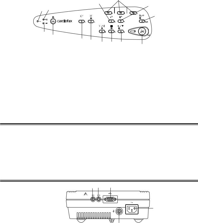
Operation Panel
7
8
9
1 3
10
2
4
|
5 |
6 |
11 |
12 |
13 |
|
|
|
14 |
||||
|
|
|
||||
|
|
|
|
|
|
|
|
Name |
|
|
|
|
Name |
1. |
AC power lamp |
|
|
8. |
Age key |
|
2. |
Battery operation lamp |
|
9. |
Sex key |
||
3. |
Battery charge lamp |
|
10. |
Auto/Manual key/lamp |
||
4. |
Power key/lamp |
|
|
11. |
Feed/Mark key |
|
5. |
Mode key |
|
|
|
12. |
Filter key/lamp |
6 |
Rhythm key/lamp |
|
13. |
Copy/CAL key lamp |
||
7. |
F1, F2, F3 function keys |
14. |
Start/Stop key/lamp |
|||
Right Side Panel
CAUTION
• When connecting an external instrument to connectors marked with  , the external instrument and this cardiograph must be connected according to the IEC60601-1-1 “Medical electrical equipment - Part 1-1: General requirements for safety - Collateral standard: Safety requirements for medical electrical systems”. Failure to follow this warning may cause electrical shock to the patient and operator.
• Do not use the output signal from the output connector for a synchronization signal such as the synchronized cardioversion signal. There is a time delay between the input ECG signal and output signal.
1 |
2 |
3 |
4
5
Name
1.EXT-IN connector
2.CRO-OUT
3.SIO connector
4.AC power cord socket
5.Equipotential ground terminal
Service Manual ECG-9620 |
1.15 |
1. GENERAL
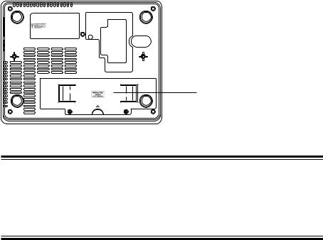
Rear Panel |
The CE mark is applied only to the |
|
ECG-9620L/M/N Electrocardiograph. |
Battery
CAUTION
Always install the battery even when the cardiograph operates on AC power. Otherwise sudden power down occurs when any electrode is detached during recording.
1.16 |
Service Manual ECG-9620 |
1. GENERAL
Composition
Standard Components
ECG-9620L |
|
|
|
RHC-0004 |
|
Record Assy |
|
|
|
||||
|
|
|
|
|
|
|
|||||||
ECG-9620M |
|
|
|
|
|
|
|
|
|
|
|
|
|
|
|
|
|
|
|
|
|
|
|
|
|
||
ECG-9620N |
|
|
|
|
|
RHC-00041 |
|
|
Motor Assy |
|
|||
|
|
|
|
|
|
|
|||||||
ECG-9620P |
|
|
|
|
|
|
|
|
|
|
|
|
|
|
|
|
|
|
|
|
|
|
|
|
|
||
ECG-9620S |
|
|
|
|
|
|
|
|
|
UTC-0009 |
|
Paper senser board |
|
|
|
|
|
|
|
|
|
|
|||||
ECG-9620T |
|
|
|
|
|
|
|
|
|
|
|
|
|
|
|
|
|
|
|
|
|
|
|
|
|
||
ECG-9620U |
|
|
|
|
|
|
|
|
|
UTC-0010 |
|
Motor sensor board |
|
|
|
|
|
|
|
|
|
|
|
||||
|
|
|
|
|
|
|
|
|
|
|
|
|
|
|
|
|
|
|
|
|
|
|
|
|
|
|
|
|
|
|
|
|
|
|
RHC-00042 |
|
Magazine Assy |
|
|||
|
|
|
|
|
|
|
|
|
|||||
|
|
|
|
|
|
|
|
|
|
|
|
||
|
|
|
|
|
|
|
|
|
|
|
|
|
|
|
|
|
|
RKC-0001 |
|
Transfer Assy (220 V) for L and P version |
|||||||
|
|
|
|
|
|||||||||
|
|
|
|
RKC-0002 |
|
Transfer Assy (230 V) for M version |
|||||||
|
|
|
|
RKC-0003 |
|
Transfer Assy (240 V) for N version |
|||||||
|
|
|
|
RKC-0004 |
|
Transfer Assy (110 V) for S version |
|||||||
|
|
|
|
RKC-0005 |
|
Transfer Assy (120 V) for T version |
|||||||
|
|
|
|
RKC-0006 |
|
Transfer Assy (127 V) for U version |
|||||||
|
|
|
|
|
|
|
|
|
|
|
|
|
|
|
|
|
|
|
|
|
|
|
|
|
|
|
|
|
|
|
|
UTC-0006 |
|
Key board |
|
|
|
||||
|
|
|
|
|
|
|
|
||||||
|
|
|
|
|
|
|
|
|
|
|
|
|
|
|
|
|
|
|
|
|
|
|
|
|
|
|
|
|
|
|
|
UTC-0007 |
|
ECG control board |
|
||||||
|
|
|
|
|
|
||||||||
|
|
|
|
|
|
|
|
|
|
|
|
|
|
|
|
|
|
|
|
|
|
|
|
|
|
|
|
|
|
|
|
UTC-0008 |
|
Power board |
|
|
|
||||
|
|
|
|
|
|
|
|
||||||
|
|
|
|
|
|
|
|
|
|
|
|
|
|
Options
KD-103E Cart
KH-801E Patient Cable Hanger
·To order a replacement assembly above, use the Code No.
·To order a replacement component inside an assembly, refer to “Section 7 Replaceablet Parts List”.
Service Manual ECG-9620 |
1.17 |

1. GENERAL
Location
Thermal Head Assy
Buzzer
Motor Assy
LCD
Transfer Assy
Key board
ECG control board
Power board
1.18 |
Service Manual ECG-9620 |
Loading...