


Nihon Kohden ZM 520PA, ZM 531PA, ZM 530PA, ZM 521PA User Manual
|
|
|
Transmitter
ZM-520PA/ZM-521PA
ZM-530PA/ZM-531PA
If you have any comments or suggestions on this |
|
manual, please contact us at: |
0614-904743 |
www.nihonkohden.com |

|
|
|
Copyright Notice
The entire contents of this manual are copyrighted by Nihon Kohden. All rights are reserved. No part of this document may be reproduced, stored, or transmitted in any form or by any means (electronic, mechanical, photocopied, recorded, or otherwise) without the prior written permission of Nihon Kohden.

|
|
|
Contents |
|
GENERAL HANDLING PRECAUTIONS ...................................................................... |
i |
WARRANTY POLICY .................................................................................................. |
iii |
Equipment Authorization Requirement ........................................................................ |
iv |
EMC RELATED CAUTION........................................................................................... |
v |
Conventions Used in this Manual and Instrument ...................................................... |
vii |
Warnings, Cautions and Notes.............................................................................. |
vii |
Explanations of the Symbols in this Manual and Instrument................................ |
viii |
Intended Use ..................................................................................................................... |
1 |
General ........................................................................................................................ |
1 |
Receiving Monitor ........................................................................................................ |
3 |
Panel Description .............................................................................................................. |
4 |
Top Panel ..................................................................................................................... |
4 |
Front Panel................................................................................................................... |
5 |
Rear Panel ................................................................................................................... |
7 |
Important Safety Information ............................................................................................. |
8 |
General ........................................................................................................................ |
8 |
Output Signal ............................................................................................................. |
12 |
Battery ....................................................................................................................... |
12 |
Transmitter Channel Management............................................................................. |
13 |
For Patients Using Implantable Pacemaker ............................................................... |
13 |
ECG Monitoring ......................................................................................................... |
14 |
SpO2 Monitoring......................................................................................................... |
15 |
Maintenance .............................................................................................................. |
17 |
Preparation on Transmitter .............................................................................................. |
19 |
Batteries..................................................................................................................... |
19 |
Handling Batteries................................................................................................ |
19 |
Battery Lifetime .................................................................................................... |
19 |
Installing (Replacing) Batteries ............................................................................ |
20 |
Situations Requiring Battery Replacement .......................................................... |
21 |
Battery Level Indication ........................................................................................ |
21 |
Attaching a Strap to the Transmitter........................................................................... |
22 |
Turning On the Transmitter......................................................................................... |
23 |
Check Items Before Use ...................................................................................... |
23 |
Check Items After Power On ................................................................................ |
24 |
Check Items After Use ......................................................................................... |
24 |
Turning Off the Transmitter......................................................................................... |
25 |
Changing the Transmitter Channel............................................................................. |
25 |
Changing Parameter and System Setup Settings ........................................................... |
26 |
Changing PARAMETER SETUP Settings.................................................................. |
26 |
Operator’s Manual ZM-520PA/521PA/530PA/531PA |
C.1 |

|
|
|
Parameter Setup Setting List ............................................................................... |
26 |
Displaying the PARAMETER SETUP Screen ...................................................... |
27 |
Changing Parameter Setup Settings.................................................................... |
28 |
Changing SYSTEM SETUP Settings......................................................................... |
31 |
System Setup Setting List .................................................................................... |
31 |
Displaying the SYSTEM SETUP Screen.............................................................. |
32 |
Changing System Setup Settings ........................................................................ |
33 |
Initializing Settings ..................................................................................................... |
36 |
Attaching Electrodes and SpO2 Probe to the Patient....................................................... |
37 |
Attaching Electrodes .................................................................................................. |
37 |
Selecting Electrode Lead ..................................................................................... |
37 |
Connecting the Electrode Lead to the Transmitter ............................................... |
38 |
Electrode Position ................................................................................................ |
39 |
Attaching Electrodes to the Patient and Connecting the Electrode Leads to |
|
Disposable Electrodes ......................................................................................... |
43 |
Checking ECG on the Transmitter Screen............................................................ |
44 |
Attaching the SpO2 Probe .......................................................................................... |
44 |
Selecting the SpO2 Probe .................................................................................... |
44 |
Connecting the SpO2 Probe to the Transmitter .................................................... |
47 |
Attaching the Probe to the Patient........................................................................ |
48 |
Locking the Keys on the Transmitter ................................................................................ |
50 |
Monitoring........................................................................................................................ |
51 |
Screen Descriptions................................................................................................... |
51 |
Check Electrodes Screen..................................................................................... |
53 |
Numeric and Waveform Screen ........................................................................... |
54 |
Waveform Review Screen .................................................................................... |
55 |
Numeric Review Screen....................................................................................... |
56 |
Display Off............................................................................................................ |
56 |
Basic Monitoring Operation ....................................................................................... |
57 |
Using the Function Key ........................................................................................ |
57 |
Suspending Alarms on the Receiving Monitor ..................................................... |
58 |
Pause Monitoring ................................................................................................. |
59 |
Resume Monitoring after Pause........................................................................... |
61 |
Confirming Patient................................................................................................ |
61 |
Turning the Display Off ......................................................................................... |
62 |
Turning the Display On after It was Turned Off..................................................... |
62 |
ECG and Respiration Monitoring ............................................................................... |
63 |
Turning ECG Measurement On/Off ...................................................................... |
66 |
Turning Respiration Measurement On/Off............................................................ |
66 |
Electrode Detachment.......................................................................................... |
66 |
SpO2 Monitoring......................................................................................................... |
67 |
Indications and Messages ............................................................................................... |
71 |
C.2 |
Operator’s Manual ZM-520PA/521PA/530PA/531PA |

|
|
|
Indication ................................................................................................................... |
71 |
Messages .................................................................................................................. |
71 |
Message Display Priority...................................................................................... |
74 |
Troubleshooting ............................................................................................................... |
75 |
Transmitter ................................................................................................................. |
75 |
ECG/Respiration ........................................................................................................ |
76 |
SpO2 ......................................................................................................................... |
77 |
Maintenance .................................................................................................................... |
78 |
1. External Check ................................................................................................. |
78 |
2. Transmitter Channel ......................................................................................... |
78 |
3. Transmitting/Receiving Signal .......................................................................... |
79 |
4. Display.............................................................................................................. |
79 |
5. Key Operation................................................................................................... |
81 |
6. ECG Check....................................................................................................... |
82 |
7. Respiration Check ............................................................................................ |
83 |
8. SpO2 Check ...................................................................................................... |
83 |
Maintenance Check Sheet ................................................................................... |
85 |
Lifetime and Disposal ...................................................................................................... |
86 |
Disposing of Used Batteries ...................................................................................... |
86 |
Battery Lifetime .................................................................................................... |
86 |
Disposal ............................................................................................................... |
86 |
Disposing of Electrodes and SpO2 Probes ................................................................ |
86 |
Disposing of Transmitter............................................................................................. |
86 |
Cleaning, Disinfection and Sterilization ........................................................................... |
87 |
Transmitter and Electrode Leads ............................................................................... |
87 |
Cleaning ............................................................................................................... |
87 |
Disinfection........................................................................................................... |
87 |
SpO2 Probe ................................................................................................................ |
88 |
Periodic Replacement Schedule ..................................................................................... |
88 |
Repair Parts Availability Policy ........................................................................................ |
88 |
Specifications .................................................................................................................. |
89 |
ZM-520PA/530PA....................................................................................................... |
89 |
Measuring Parameters ......................................................................................... |
89 |
Transmitting Data ................................................................................................. |
89 |
Display.................................................................................................................. |
89 |
Displayed Data ..................................................................................................... |
89 |
ECG ..................................................................................................................... |
89 |
Respiration Measurement .................................................................................... |
91 |
SpO2 Measurement (ISO 9919: 2005 compliance) .............................................. |
91 |
Transmitter ........................................................................................................... |
93 |
Power Requirements ............................................................................................ |
93 |
Dimension and Weight ......................................................................................... |
94 |
Operator’s Manual ZM-520PA/521PA/530PA/531PA |
C.3 |

|
|
|
Environment ......................................................................................................... |
94 |
Safety Standards.................................................................................................. |
94 |
Electromagnetic Compatibility.............................................................................. |
95 |
Electromagnetic Emissions .................................................................................. |
95 |
Electromagnetic Immunity .................................................................................... |
96 |
Recommended Separation Distances between Portable and Mobile RF |
|
Communications Equipment ................................................................................ |
98 |
Recovery Time after Defibrillation ........................................................................ |
98 |
System Composition for EMC Test....................................................................... |
98 |
ZM-521PA/531PA....................................................................................................... |
99 |
Measuring Parameters ......................................................................................... |
99 |
Transmitting Data ................................................................................................. |
99 |
Display.................................................................................................................. |
99 |
Displayed Data ..................................................................................................... |
99 |
ECG ..................................................................................................................... |
99 |
Respiration Measurement .................................................................................. |
101 |
SpO2 Measurement (ISO 9919: 2005 compliance) ............................................ |
101 |
Transmitter ......................................................................................................... |
103 |
Power Requirements .......................................................................................... |
103 |
Dimension and Weight ....................................................................................... |
104 |
Environment ....................................................................................................... |
104 |
Safety Standards................................................................................................ |
104 |
Electromagnetic Compatibility............................................................................ |
105 |
Electromagnetic Emissions ................................................................................ |
105 |
Electromagnetic Immunity .................................................................................. |
106 |
Recommended Separation Distances between Portable and Mobile RF |
|
Communications Equipment .............................................................................. |
108 |
Recovery Time after Defibrillation ...................................................................... |
108 |
System Composition for EMC Test..................................................................... |
108 |
Standard Accessories.................................................................................................... |
109 |
Options .......................................................................................................................... |
110 |
Transmitter ......................................................................................................... |
110 |
ECG/RESP......................................................................................................... |
110 |
SpO2 .................................................................................................................. |
111 |
Transmission Frequencies ............................................................................................. |
112 |
C.4 |
Operator’s Manual ZM-520PA/521PA/530PA/531PA |

|
|
|
GENERAL HANDLING PRECAUTIONS
This device is intended for use only by qualified medical personnel. Use only Nihon Kohden approved products with this device. Use of non-
approved products or in a non-approved manner may affect the performance specifications of the device. This includes, but is not limited to, batteries, recording paper, pens, extension cables, electrode leads, input boxes and AC power.
Please read these precautions thoroughly before attempting to operate the instrument.
1.To safely and effectively use the instrument, its operation must be fully understood.
2.When installing or storing the instrument, take the following precautions:
(1)Avoid moisture or contact with water, extreme atmospheric pressure, excessive humidity and temperatures, poorly ventilated areas, and dust, saline or sulphuric air.
(2)Place the instrument on an even, level floor. Avoid vibration and mechanical shock, even during transport.
(3)Avoid placing in an area where chemicals are stored or where there is danger of gas leakage.
(4)The power line source to be applied to the instrument must correspond in frequency and voltage to product specifications, and have sufficient current capacity.
(5)Choose a room where a proper grounding facility is available.
3.Before Operation
(1)Check that the instrument is in perfect operating order.
(2)Check that the instrument is grounded properly.
(3)Check that all cords are connected properly.
(4)Pay extra attention when the instrument is in combination with other instruments to avoid misdiagnosis or other problems.
(5)All circuitry used for direct patient connection must be doubly checked.
(6)Check that battery level is acceptable and battery condition is good when using batteryoperated models.
4.During Operation
(1)Both the instrument and the patient must receive continual, careful attention.
(2)Turn power off or remove electrodes and/or transducers when necessary to assure the patient’s safety.
(3)Avoid direct contact between the instrument housing and the patient.
Operator’s Manual ZM-520PA/521PA/530PA/531PA |
i |

|
|
|
5.To Shutdown After Use
(1)Turn power off with all controls returned to their original positions.
(2)Remove the cords gently; do not use force to remove them.
(3)Clean the instrument together with all accessories for their next use.
6.The instrument must receive expert, professional attention for maintenance and repairs. When the instrument is not functioning properly, it should be clearly marked to avoid operation while it is out of order.
7.The instrument must not be altered or modified in any way.
8.Maintenance and Inspection:
(1)The instrument and parts must undergo regular maintenance inspection at least every 6 months.
(2)If stored for extended periods without being used, make sure prior to operation that the instrument is in perfect operating condition.
(3)Technical information such as parts list, descriptions, calibration instructions or other information is available for qualified user technical personnel upon request from your Nihon Kohden representative.
9.When the instrument is used with an electrosurgical instrument, pay careful attention to the application and/or location of electrodes and/or transducers to avoid possible burn to the patient.
10.When the instrument is used with a defibrillator, make sure that the instrument is protected against defibrillator discharge. If not, remove patient cables and/or transducers from the instrument to avoid possible damage.
ii |
Operator’s Manual ZM-520PA/521PA/530PA/531PA |

|
|
|
WARRANTY POLICY
Nihon Kohden Corporation (NKC) shall warrant its products against all defects in materials and workmanship for one year from the date of delivery. However, consumable materials such as recording paper, ink, stylus and battery are excluded from the warranty.
NKC or its authorized agents will repair or replace any products which prove to be defective during the warranty period, provided these products are used as prescribed by the operating instructions given in the operator’s and service manuals.
No other party is authorized to make any warranty or assume liability for NKC’s products. NKC will not recognize any other warranty, either implied or in writing. In addition, service, technical modification or any other product change performed by someone other than NKC or its authorized agents without prior consent of NKC may be cause for voiding this warranty.
Defective products or parts must be returned to NKC or its authorized agents, along with an explanation of the failure. Shipping costs must be pre-paid.
This warranty does not apply to products that have been modified, disassembled, reinstalled or repaired without Nihon Kohden approval or which have been subjected to neglect or accident, damage due to accident, fire, lightning, vandalism, water or other casualty, improper installation or application, or on which the original identification marks have been removed.
In the USA and Canada other warranty policies may apply.
CAUTION
United States law restricts this product to sale by or on the order of a physician.
Operator’s Manual ZM-520PA/521PA/530PA/531PA |
iii |

|
|
|
Equipment Authorization Requirement
This device complies with Part 15 of the FCC (Federal Communications Commission) Rules. Operation is subject to the following two conditions:
(1)this device may not cause harmful interference, and
(2)this device must accept any interference received, including interference that may cause undesired operation.
This device complies with Part 95 Subpart H of the FCC Rules to be used in wireless medical telemetry service.
Operation of this equipment requires the prior coordination with a frequency coordinator designated by FCC for the Wireless Medical Telemetry Service.
CAUTION
To comply with the FCC radio frequency (RF) exposure compliance requirements, no change to the antenna or the device is permitted. Any change to the antenna or the device could result in the device, exceeding the RF exposure requirements and void user’s authority to operate this device.
NOTE
•Use this device only indoors.
•This device has been tested and complies with FCC radiation exposure limits set forth for an uncontrolled environment. The RF transmission power from the antenna conforms to the general public FCC RF Exposure Guidelines in Supplement C to OET65 limit of Specific Absorption Rate (SAR) 1.6 W/kg. The maximum SAR value measured from this device was extremely smaller than 1.6 W/kg. This device must not
be located together with or operated in conjunction with any other unspecified antenna or transmitter.
•The devices require registration and deployment by an authorized frequency coordinator. The ASHE (American Society for Healthcare Engineering) has been designated by the FCC to manage the WMTS frequencies. This device has frequency bands which may not be used in some areas. For details, contact your Nihon Kohden representative. For details on the guidelines, refer to the ASHE home page.
iv |
Operator’s Manual ZM-520PA/521PA/530PA/531PA |
|
|
|
EMC RELATED CAUTION
This equipment and/or system complies with the International Standard IEC 60601- 1-2 for electromagnetic compatibility for medical electrical equipment and/or system. However, an electromagnetic environment that exceeds the limits or levels stipulated in the IEC 60601-1-2, can cause harmful interference to the equipment and/or system or cause the equipment and/or system to fail to perform its intended function or degrade its intended performance. Therefore, during the operation of the equipment and/or system, if there is any undesired deviation from its intended operational performance, you must avoid, identify and resolve the adverse electromagnetic effect before continuing to use the equipment and/or system.
The following describes some common interference sources and remedial actions:
1.Strong electromagnetic interference from a nearby emitter source such as an authorized radio station or cellular phone:
Install the equipment and/or system at another location if it is interfered with by an emitter source such as an authorized radio station. Keep the emitter source such as cellular phone away from the equipment and/or system.
2.Effect of direct or indirect electrostatic discharge:
Make sure all users and patients in contact with the equipment and/or system are free from direct or indirect electrostatic energy before using it.
3.Electromagnetic interference with any radio wave receiver such as radio or television:
If the equipment and/or system interferes with any radio wave receiver, locate the equipment and/or system as far as possible from the radio wave receiver.
4.Electromagnetic interference with any radio wave receiver such as radio or television:
If the equipment and/or system interferes with any radio wave receiver, locate the equipment and/or system as far as possible from the radio wave receiver.
5.Interference of lightning:
When lightning occurs near the location where the equipment and/or system is installed, it may induce an excessive voltage in the equipment and/or system. In such a case, disconnect the AC power cord from the equipment and/or system and operate the equipment and/or system by battery power, or use an uninterruptible power supply.
Operator’s Manual ZM-520PA/521PA/530PA/531PA |
v |

|
|
|
6.Use with other equipment:
When the equipment and/or system is adjacent to or stacked with other equipment, the equipment and/or system may affect the other equipment. Before use, check that the equipment and/or system operates normally with the other equipment.
7.Use of unspecified accessory, transducer and/or cable:
When an unspecified accessory, transducer and/or cable is connected to this equipment and/or system, it may cause increased electromagnetic emission or decreased electromagnetic immunity. The specified configuration of this equipment and/or system complies with the electromagnetic requirements with the specified configuration. Only use this equipment and/or system with the specified configuration.
8.Use of unspecified configuration:
When the equipment and/or system is used with the unspecified system configuration different than the configuration of EMC testing, it may cause increased electromagnetic emission or decreased electromagnetic immunity. Only use this equipment and/or system with the specified configuration.
9.Measurement with excessive sensitivity:
The equipment and/or system is designed to measure bioelectrical signals with a specified sensitivity. If the equipment and/or system is used with excessive sensitivity, artifact may appear by electromagnetic interference and this may cause mis-diagnosis. When unexpected artifact appears, inspect the surrounding electromagnetic conditions and remove this artifact source.
If the above suggested remedial actions do not solve the problem, consult your Nihon Kohden representative for additional suggestions.
vi |
Operator’s Manual ZM-520PA/521PA/530PA/531PA |

|
|
|
Conventions Used in this Manual and Instrument
Warnings, Cautions and Notes
Warnings, cautions and notes are used in this manual to alert or signal the reader to specific information.
WARNING
A warning alerts the user to the possible injury or death associated with the use or misuse of the instrument.
CAUTION
A caution alerts the user to possible injury or problems with the instrument associated with its use or misuse such as instrument malfunction, instrument failure, damage to the instrument, or damage to other property.
NOTE
A note provides specific information, in the form of recommendations, prerequirements, alternative methods or supplemental information.
Operator’s Manual ZM-520PA/521PA/530PA/531PA |
vii |
|
|
|
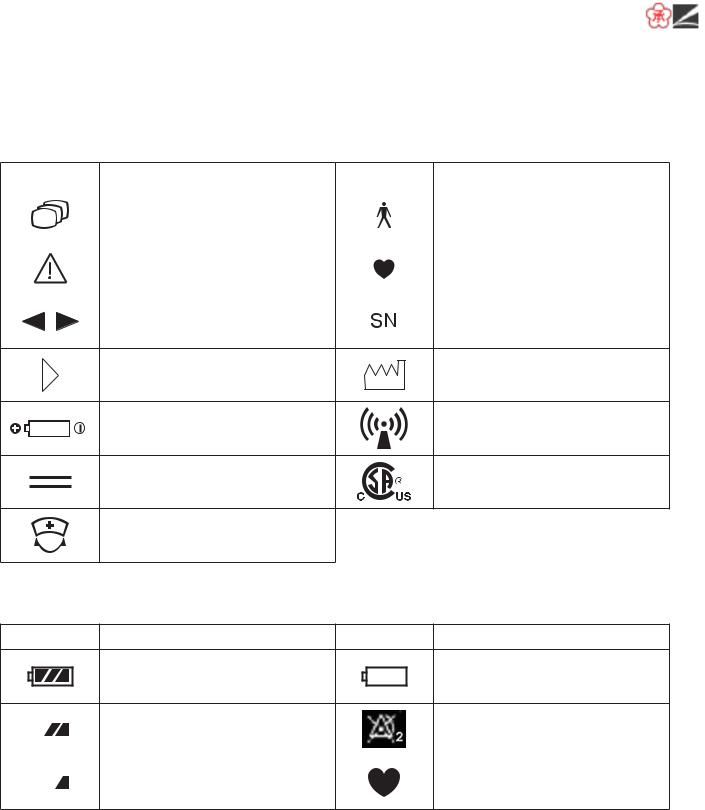
Explanations of the Symbols in this Manual and Instrument
The following symbols found in this manual/instrument bear the respective descriptions as given.
On Panel
Symbol |
Description |
Symbol |
Description |
||||||
|
Change screen |
|
|
|
|
|
|
|
Defibrillation proof type BF |
|
|
|
|
|
|
|
|
||
|
|
|
|
|
|
|
|
||
|
|
|
|
|
|
|
|
applied part |
|
|
|
|
|
|
|
|
|
||
|
|
|
|
|
|
|
|
|
|
|
|
|
|
|
|
|
|
|
|
|
|
|
|
|
|
|
|
|
|
|
Attention, consult operator’s |
|
|
|
|
|
|
|
Defibrillation proof type CF |
|
|
|
|
|
|
|
|
||
|
|
|
|
|
|
|
|
||
|
manual |
|
|
|
|
|
|
|
applied part |
|
|
|
|
|
|
|
|
||
|
|
|
|
|
|
|
|
||
|
|
|
|
|
|
|
|
|
|
|
Moves cursor, scrolls data |
|
|
|
|
|
|
|
Serial number |
|
|
|
|
|
|
|
|
||
Direction for attaching battery
Date of manufacture
cover
Direction for inserting battery
RF transmitter
Non-ionizing radiation
Direct current |
cCSAus mark |
Call key
On LCD
Symbol |
Description |
Symbol |
Description |
Batteries are fully charged
Batteries are almost empty
Replace battery
|
|
|
Batteries are getting low |
Alarm suspended |
|
|
|
||
|
|
|||
|
|
|
|
|
|
|
|
Batteries are low |
QRS/pulse sync mark |
|
|
|
||
|
|
|
viii |
Operator’s Manual ZM-520PA/521PA/530PA/531PA |

|
|
|
Intended Use
General
The ZM-520PA and ZM-521PA transmitter transmits ECG and respiration from a patient to a Nihon Kohden monitor for continuous monitoring. The front LCD displays ECG, numeric values of monitoring parameters, messages and battery condition.* It also displays the compressed waveform and numeric data of the latest 10 minutes.
The ZM-530PA and ZM-531PA transmitter transmits ECG, respiration and pulse waveforms and SpO2 from a patient to a Nihon Kohden monitor for continuous monitoring. The front LCD displays ECG (or pulse wave), numeric values of monitoring parameters, messages and battery condition.* It also displays the compressed waveform and numeric data of the latest 10 minutes.
* Essential performance of this transmitter.
The difference between the ZM-520PA/530PA and ZM-521PA/531PA is the transmission frequency range.
ZM-520PA/530PA: 608.0250 MHz (channel number 9002) to 613.9750 MHz (channel number 9478)
ZM-521PA/531PA: 1395.0250 MHz (channel number E002) to 1399.9750 MHz (channel number E398)
1427.0250 MHz (channel number E502) to 1431.9750 MHz (channel number E898)
The transmitter channel can be changed with a QI-901PK channel writer.
Read the operator’s manual for the receiving monitor together with this manual before use.
WARNING
Do not diagnose a patient based only on data acquired by the transmitter. Overall judgement must be performed by a physician who understands the features, limitations and characteristics of the transmitter and by reading the biomedical signals acquired by other instruments.
WARNING
Do not use the same transmitter for more than one patient at the same time. Do not connect different sensors from different patients to the same transmitter.
Operator’s Manual ZM-520PA/521PA/530PA/531PA |
1 |

|
|
|
CAUTION
•Do not use the same channel for different patients. If the same channel is used for two patients, the two patients’ data will be lost due to mutual modulation
interference, or another patient’s data may appear on the receiving monitor screen.
•Do not use two transmitters with adjacent channels in the same hospital. If transmitters with adjacent channels are used, their radio waves interfere with each other.
CAUTION
Signal loss and artifact may occur because of the multipath cancellation* when using
a transmitter.
* Multipath Cancellation (Standing Wave Interference):
When a radio wave reflects off a surface, there may be some points in the room where the reflected and direct waves are exactly out of phase. At these points in the room, the reflected and direct waves cancel each other out so that the signal strength is decreased. Locations where signal loss occurs are called “null spots”. If the transmitter is moving or nearby people or objects are moving, null spots can occur anytime and anywhere.
NOTE
•To prevent interference between channels, assign a channel administrator in the hospital and only he or she should manage channel assignment.
•Use Nihon Kohden parts and accessories to assure maximum performance from your instrument.
•For stable signal reception, it is recommended to use a diversity antenna system on the receiving monitor. Otherwise, spike noise from transient fading of electric field strength (for example, people moving) may interfere with the transmitter signal and may be mistaken as an arrhythmia on the receiving monitor.
•For details on antennas and antenna construction, contact your Nihon Kohden representative. You can also refer to the Telemetry System Installation Guide.
2 |
Operator’s Manual ZM-520PA/521PA/530PA/531PA |

|
|
|
Receiving Monitor
Any Nihon Kohden receiving monitor (central monitor with multiple patient receiver) can receive signals from this transmitter as long as the protocol version and channel setting are the same on the receiving monitor and transmitter.
NOTE
•For details on the receiving monitor and upgrade information, contact your Nihon Kohden representative.
•The transmitter does not give any alarm other than a “no battery” alarm. Alarms must be managed on the receiving monitor.
•To use protocol 51, the ORG-9100A/ORG-9110A multiple patient receiver software version 03-03 or later is required. For the protocol setting, refer to the “Changing SYSTEM SETUP Settings” section.
Operator’s Manual ZM-520PA/521PA/530PA/531PA |
3 |

|
|
|
Panel Description
Top Panel
ZM-530PA/531PA only
SpO2 socket
Connects the SpO2 probe.
For attaching a strap.
ECG/RESP socket
Connects the electrode lead for measuring ECG and/or respiration by the impedance method.
WARNING
Before defibrillation, all persons must keep clear of the bed and must not touch the patient or any equipment or cord connected to the patient. Failure to follow this warning may cause electrical shock or injury.
WARNING
When performing defibrillation, discharge as far as possible from electrodes, patches and any gel, cream or medicine on the chest of the patient. If there is a possibility that the defibrillator paddle could touch these materials, remove them from the patient. If the defibrillator paddle directly contacts these materials, the discharged energy may cause skin burn to the patient.
WARNING
When the transmitter is used with an electrosurgical unit (ESU), firmly attach the entire area of the ESU return plate. Otherwise, the current from the ESU flows into the electrodes of the transmitter, causing electrical burn where the electrodes are attached. For details, refer to the ESU manual.
CAUTION
Do not shake or swing the transmitter while holding the leads or cables connected to the transmitter. The transmitter may come off and injure someone or damage surrounding instruments.
4 |
Operator’s Manual ZM-520PA/521PA/530PA/531PA |

|
|
|
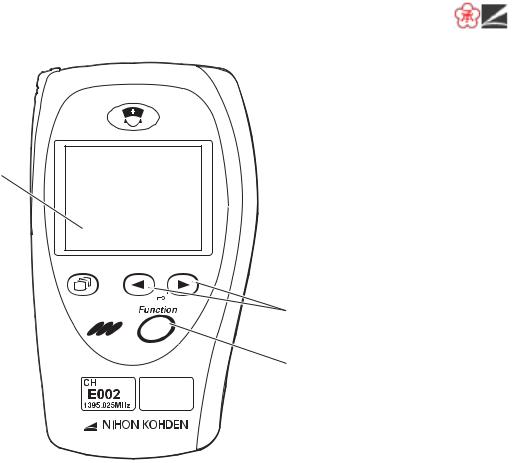
Front Panel
1 
2
3 
6
4 
7
5 
No. |
Name |
Description |
1 |
CALL key |
When this key is pressed, a “peep” sounds at the transmitter, |
|
|
and “CALL” message appears at the monitor. Depending on |
|
|
the settings on the monitor, an ECG waveform is recorded when |
|
|
this key is pressed. |
2 |
LCD |
Displays numeric values, ECG or pulse wave, messages and |
|
|
battery status. For details, refer to the “Screen Descriptions” |
|
|
section. |
3 |
Screen key |
Toggles the screen in the following order. |
After power on: Start up → Check electrodes → Numeric and waveform → Waveform review → Numeric review → Display off → Check electrodes …
After auto display off: Numeric and waveform → Waveform review → Numeric review → Display off → Check electrodes → Numeric and waveform …
On a SETUP or CHECK screen, this key cancels changing setting or exits the screen.
Operator’s Manual ZM-520PA/521PA/530PA/531PA |
5 |
|
|
|
1 
2
3 
6
4 
7
5 
No. |
Name |
Description |
4 |
Infrared receiver |
Used for upgrading the transmitter software. |
5Channel number label Indicates the channel number of the transmitter.
6 |
Lead/Scroll keys |
On the numeric and waveform screen, these keys change the |
|
|
ECG lead. |
|
|
On the waveform review screen, these keys scroll data. |
|
|
On a SETUP screen, these keys move the cursor. |
7 |
Function key |
Depending on the setting on the transmitter, this key suspends |
|
|
alarms, pauses monitoring on the receiving monitor or transmits |
|
|
“Patient confirmed” message. |
On a SETUP screen, this key registers the selected setting and moves the cursor to the next setting item.
On a CHECK screen, this key starts or stops the maintenance test.
6 |
Operator’s Manual ZM-520PA/521PA/530PA/531PA |
|
|
|
Rear Panel
ZM-530PA/531PA only
Refer to the WARNING below.
Refer to the “Explanations of the Symbols in this Manual and Instrument” section.
Refer to the “Explanations of the Symbols in this Manual and Instrument” section.
Refer to the WARNING below.
Battery case:
Contains two alkaline dry cell batteries (AA TYPE).
WARNING
Close the battery case cover during operation. If the transmitter is used with the battery case cover open, anyone who touches the opened battery case may receive an electrical shock when defibrillation is performed. Touching the opened battery case may cause electrostatic discharge and intermittently interfere with the waveform or data.
WARNING
This transmitter is not waterproof. If detergent or liquid spills into the transmitter, stop using it and contact your Nihon Kohden representative. If a wet transmitter is used, the patient or operator may receive an electrical shock or injury.
Operator’s Manual ZM-520PA/521PA/530PA/531PA |
7 |

|
|
|
Important Safety Information
General
WARNING
Never use the transmitter in the presence of any flammable anesthetic gas or high concentration oxygen atmosphere. Failure to follow this warning may cause explosion or fire.
WARNING
Never use the transmitter in a hyperbaric oxygen chamber. Failure to follow this warning may cause explosion or fire.
WARNING
Do not take this transmitter into the MRI test room. This transmitter is not designed to be used during MRI tests.
WARNING
When performing MRI test, remove all electrodes and probe from the patient which are connected to this transmitter. Failure to follow this warning may cause skin burn on the patient. For details, refer to the MRI manual.
WARNING
Before defibrillation, all persons must keep clear of the bed and must not touch the patient or any equipment or cord connected to the patient. Failure to follow this warning may cause electrical shock or injury.
WARNING
When performing defibrillation, discharge as far as possible from electrodes, patches and any gel, cream or medicine on the chest of the patient. If there is a possibility that the defibrillator paddle could touch these materials, remove them from the patient. If the defibrillator paddle directly contacts these materials, the discharged energy may cause skin burn to the patient.
8 |
Operator’s Manual ZM-520PA/521PA/530PA/531PA |

|
|
|
WARNING
When the transmitter is used with an electrosurgical unit (ESU), firmly attach the entire area of the ESU return plate. Otherwise, the current from the ESU flows into the electrodes of the transmitter, causing electrical burn where the electrodes are attached. For details, refer to the ESU manual.
WARNING
This transmitter is not waterproof. If detergent or liquid spills into the transmitter, stop using it and contact your Nihon Kohden representative. If a wet transmitter is used, the patient or operator may receive an electrical shock or injury.
WARNING
Close the battery case cover during operation. If the transmitter is used with the battery case cover open, anyone who touches the opened battery case may receive an electrical shock when defibrillation is performed. Touching the opened battery case may cause electrostatic discharge and intermittently interfere with the waveform or data.
WARNING
When the signal is unstable, keep the patient under close observation. When the signal is unstable, the monitoring and alarm are not reliable and the receiving monitor cannot detect a sudden change of the patient’s condition. This may cause critical changes in the patient condition to be overlooked. Install an appropriate antenna system to ensure stable signal condition.
WARNING
Do not use the same transmitter for more than one patient at the same time. Do not connect different sensors from different patients to the same transmitter.
Operator’s Manual ZM-520PA/521PA/530PA/531PA |
9 |

|
|
|
WARNING
Do not diagnose a patient based only on data acquired by the transmitter. Overall judgement must be performed by a physician who understands the features, limitations and characteristics of the transmitter and by reading the biomedical signals acquired by other instruments.
CAUTION
Only use Nihon Kohden specified electrodes, electrode leads and SpO2 probes. Otherwise, the maximum performance from the transmitter cannot be guaranteed.
CAUTION
Do not reuse disposable parts and accessories.
CAUTION
The measurement values and displayed waveforms on the transmitter and receiving monitor may be different due to timing delay of the display or difference in detection settings.
CAUTION
Do not shake or swing the transmitter while holding the leads or cables connected to the transmitter. The transmitter may come off and injure someone or damage surrounding instruments.
10 |
Operator’s Manual ZM-520PA/521PA/530PA/531PA |

|
|
|
CAUTION
Signal loss and artifact may occur because of the multipath cancellation* when using a transmitter.
*Multipath Cancellation (Standing Wave Interference):
When a radio wave reflects off a surface, there may be some points in the room where the reflected and direct waves are exactly out of phase. At these points in the room, the reflected and direct waves cancel each other out so that the signal strength is decreased. Locations where signal loss occurs are called “null spots”. If the transmitter is moving or nearby people or objects are moving, null spots can occur anytime and anywhere.
CAUTION
Turn off the power of mobile phones, small wireless devices and other devices which produce strong electromagnetic interference around a patient (except for devices allowed by the hospital administrator). Radio waves from devices such as mobile phones or small wireless devices may be mistaken as pulse waves or respiration waves and the displayed data may be incorrect.
CAUTION
•Do not use the same channel for different patients. If the same
channel is used for two patients, the two patients’ data will be lost due to mutual modulation interference, or another patient’s data may appear on the receiving monitor screen.
•Do not use two transmitters with adjacent channels in the same hospital. If transmitters with adjacent channels are used, their radio waves interfere with each other.
Operator’s Manual ZM-520PA/521PA/530PA/531PA |
11 |

|
|
|
Output Signal
WARNING
Do not use the output signal from the receiving monitor as the synchronization signal for other equipment such as IABP, MRI, echocardiography or defibrillator. There may be time delay between the monitor and the other equipment caused by waveform transmission delay and spike noise may interfere on the output signal and be mistaken as a trigger.
Battery
WARNING
Do not use NiMH batteries for this transmitter. Some operating environments may cause NiMH batteries to produce gas and explode.
CAUTION
Battery replacement must be performed by the operator. When replacing the batteries of a transmitter that is currently used for a patient, disconnect the electrode leads from the transmitter before replacing batteries or do not touch the patient during replacement.
CAUTION
When the transmitter is not in use, remove the batteries. When the batteries are installed, battery power is consumed even when measurement is not performed.
CAUTION
Do not handle the batteries with wet hands.
CAUTION
Refer to the battery manual for details on handling the batteries.
12 |
Operator’s Manual ZM-520PA/521PA/530PA/531PA |

|
|
|
Transmitter Channel Management
WARNING
The following actions must be taken to properly receive the transmitter signal of the correct patient on the receiving instrument. Otherwise, there may be signal loss or signals may mix causing a serious accident, such as monitoring a different patient.
•Assign a channel administrator in the hospital and only he or she should manage channel assignment.
•The channel administrator must manage the channels in the facility so that there is no signal interference.
•When the transmitter channel is changed, the channel administrator must check that the channel on the receiving monitor is also changed and the signal is properly received.
•The channel administrator must replace the channel number label on the transmitter with the new one after changing the channel.
For Patients Using Implantable Pacemaker
WARNING
Interaction Between Minute Ventilation Rate-Adaptive Pacemakers and Cardiac Monitoring and Diagnostic Equipment*
The bioelectric impedance measurement sensor of a minute ventilation rate-adaptive implantable pacemaker may be affected by transmitter which is connected to the same patient. If this occurs, the pacemaker may pace at its maximum rate and the transmitter may give incorrect data to the monitor. If this occurs, disconnect the electrode leads from the patient or change the setting on the pacemaker by referring to the pacemaker’s manual. For more details, contact your pacemaker representative or Nihon Kohden representative.
*Minute ventilation is sensed in rate-adaptive pacemakers by a technology known as bioelectric impedance measurement (BIM). Many medical devices in addition to pacemakers use this technology. When one of these devices is used on a patient with an active, minute ventilation rate-adaptive pacemaker, the pacemaker may erroneously interpret the mixture of BIM signals created in the patient, resulting in an elevated pacing rate.
For more information, see the FDA web site. http://www.fda.gov/cdrh/safety.html
Operator’s Manual ZM-520PA/521PA/530PA/531PA |
13 |

|
|
|
ECG Monitoring
WARNING
After attaching the electrode to the patient and connecting the electrode lead to the transmitter, check that electrodes are attached to the patient and check that the electrode lead is connected to the transmitter properly. When the electrodes are removed from the patient, do not touch the metal part of the electrode with bare hands or let the metal part of the electrode contact the metal part of the bed or any other conductive parts. Failure to follow this warning may cause electrical shock or injury to the patient by discharged energy.
WARNING
The transmitter detects the pacemaker pulse and rejects the pacemaker pulse from the heart rate count. However, all of the pacemaker pulse might not be rejected. If the pacemaker pulse is not rejected, the pacemaker pulse is detected as QRS and false heart rate may be indicated. Keep pacemaker patients under close observation.
*For the pacemaker pulse rejection capability of ZM-520PA/521PA/530PA/531PA transmitter refer to the “Specifications - ECG” section.
WARNING
The pacemaker pulse can be overlooked or detected as QRS. You cannot confirm the pacemaker operation only from the detected pacemaker pulse.
CAUTION
Only use Nihon Kohden specified electrodes and electrode leads. When other type of electrodes or electrode leads are used, the “CHECK ELECTRODES” message may be displayed and ECG monitoring may stop.
CAUTION
When the “ELECTRODE OFF” or “CHECK ELECTRODES” message is displayed on the receiving monitor, ECG is not monitored properly and the ECG alarm does not function. Check the electrode, electrode leads, and if necessary, replace with new ones.
CAUTION
Hold the connector of the electrode lead when connecting/disconnecting the electrode lead. If you disconnect the electrode lead by pulling the lead, it damages the electrode lead.
14 |
Operator’s Manual ZM-520PA/521PA/530PA/531PA |

|
|
|
SpO2 Monitoring
WARNING
SpO2 measurement may be incorrect in the following cases.
•When the patient’s carboxyhemoglobin or methemoglobin increases abnormally.
•When dye is injected in the blood.
•When using an electrosurgical unit.
•During CPR.
•When measuring at a site with venous pulse.
•When there is body movement.
•When the pulse wave is small (insufficient peripheral circulation).
WARNING
When monitoring SpO2 of a patient who is receiving photodynamic therapy, the light from the finger probe sensor may cause a burn. Photodynamic therapy uses a photosensitizing agent that has a side effect of photosensitivity.
The SpO2 probe manufactured by Nihon Kohden have two wavelengths with peaks in the range of 650 and 950 nm. The maximum light intensity is less than 5.5 mW.
WARNING
•When using the TL-201T finger probe, do not fasten the probe and cable to the finger by wrapping with tape. This may cause burn,
congestion or pressure necrosis from poor blood circulation.
•When using probes other than the TL-201T finger probe, to avoid poor circulation, do not wrap the tape too tight. Check the blood circulation condition by observing the skin color and congestion at the skin peripheral to the probe attachment site. Even for short-term monitoring, there may be burn or pressure necrosis from poor blood circulation, especially on neonates or low birth weight infants whose skin is delicate. Accurate measurement cannot be performed on a site with poor peripheral circulation.
WARNING
Check the circulation condition by observing the skin color at the measurement site and pulse waveform. Change the measurement site every 8 hours for disposable probes and every 4 hours for reusable probes (every 8 hours for TL-631T series probe). The skin temperature may increase at the attached site by 2 or 3°C (4 or 5°F) and cause a burn or pressure necrosis. When using the probe on the following patients, take extreme care and change the measurement site more frequently according to symptoms and degree.
•Patient with a fever
•Patient with insufficient peripheral circulation
•Neonate or low birth weight infant with delicate skin
Operator’s Manual ZM-520PA/521PA/530PA/531PA |
15 |

|
|
|
WARNING
When not monitoring SpO2, disconnect the SpO2 cable from the transmitter. Otherwise, noise from the probe sensor may interfere and incorrect data is displayed on the screen.
CAUTION
Refer to the probe instruction manual for details.
CAUTION
The disposable probe is not sterilized. Use the disposable probe only for a single patient. Never reuse the disposable probe for another patient because it causes cross infection.
CAUTION
Do not attach the probe to the same limb that is used for NIBP measurement or an IBP catheter. The SpO2 measurement may be incorrect.
CAUTION
While a patient is on medication which causes vasodilation, the pulse waveform may change and in rare cases the SpO2 value might not be displayed.
CAUTION
Normal external light does not affect monitoring but strong light such as a surgical light or sunlight may affect monitoring. If affected, cover the measuring site with a blanket.
CAUTION
When a message indicates a faulty probe, stop monitoring and replace the probe with a new one.
CAUTION
Do not use a damaged or disassembled probe. It causes incorrect measurement and may injure the patient.
CAUTION
Do not use a probe which is deteriorated by aging. Accurate measurement cannot be performed.
16 |
Operator’s Manual ZM-520PA/521PA/530PA/531PA |
 Loading...