

Page 1

MTS Insight™ Material Testing Systems
Product Information
1kN to 300kN
l
100-146-666 E
Page 2

Copyright information © 2007 MTS Systems Corporation. All rights reserved.
Trademark information MTS and TestWorks are registered trademarks of MTS Systems
Corporation.
MTS Insight is a Trademark of MTS Systems Corporation.
Contact information MTS Systems Corporation
14000 Technology Drive
Eden Prairie, Minnesota 55344-2290 USA
Toll Free Phone: 800-328-2255 (within the U.S. or Canada)
Phone: 952-937-4000 (outside the U.S. or Canada)
Fax: 952-937-4515
E-mail: info@mts.com
http://www.mts.com
ISO 9001 Certified
Publication information
Manual Part Number Publication Date
100-146-666 A January 2006
(build 041306)
100-146-666 B June 2006
100-146-666 C June 2006
(build 081006)
100-146-666 D December 2006
(build 051007)
100-146-666 E May 2007
2
Insight Material Testing System
Page 3

Contents
Preface 5
About This Manual 6
Conventions 7
Technical Support 9
EC Declaration of Conformity 13
MTS Insight 1 kN to 100 kN 13
MTS Insight 150 kN to 300 kN 14
Introduction 17
Description 18
Specifications 20
General Specifications 20
Model Specifications 21
Crosshead Detail 34
Baseplate Detail 35
Installation 39
Moving the 1 kN and 2 kN Frames 40
Moving the 5 kN and Higher Frames 42
Machine location and ventilation 43
Controller Connections 44
Connecting the main power 44
Transformer Requirements for MTS Insight 150, 200 and 300 Machines 48
Installing cables 50
Controller Connectors 50
Operation 57
Hazard Icons 58
Main Power Switch (I/O) and E-Stop 59
Insight Material Testing System Contents
3
Page 4

Travel Limit Switches (Physical Limits) 60
Crush Zone Hazards 62
Fixture Mounting 63
Load Cell Mounting 64
Handset Control 68
Maintenance 71
Appendix 73
Additional Digital I/O Information 73
4
Contents
Insight Material Testing System
Page 5

Preface
Safety first! Before you attempt to use your MTS equipment in your test system, read and
Contents About This Manual 6
understand the Safety manual. Like an automobile, your test system is very
useful—but if misused, it is capable of deadly force. You should not be
afraid of your test system, but you should always maintain a healthy respect
for it.
Improper installation, operation, or maintenance of MTS equipment in your
test system can result in hazardous conditions that can cause severe personal
injury or death, and damage to your equipment and specimen. Again, read
and understand the Safety manual before you continue. It is very important
that you remain aware of hazards that apply to your test system.
Conventions 7
Technical Support 9
EC Declaration of Conformity 13
MTS Insight 1 kN to 100 kN 13
MTS Insight 150 kN to 300 kN 14
Insight Material Testing System Preface
5
Page 6

About This Manual
About This Manual
Purpose This manual provides detailed information about the MTS Insight™
Material Testing Systems. The information includes an overview of all the
models available, installation, operation, and maintenance.
Summary This manual includes the following sections.
Introduction This section reviews the MTS Insight material testing system models, gives
you a description of a typical frame, and lists the environmental
specifications. This section also provides the technical frame specifications
of each MTS Insight frame model and line drawings of the crosshead and
baseplate details.
Installation This section gives you specific instructions for properly moving MTS
Insight frames, cable installation, and line drawings of the basic controller.
Operation This section provides a graphic of the manual handset control and handset
functions. Other areas such as travel limit switches and fixture and load cell
mounting are reviewed.
Maintenance This section gives you a complete guide to the preventive maintenance
schedule for all MTS Insight frames.
Preface
6
Insight Material Testing System
Page 7

Conventions
DANGER
WARNING
Conventions
The following paragraphs describe some of the conventions that are used in
your MTS manuals.
Hazard conventions Hazard notices are embedded in this manual and contain safety information
that is specific to the task to be performed. Hazard notices immediately
precede the step or procedure that may lead to an associated hazard. Read all
hazard notices carefully and follow the directions that are given. Three
different levels of hazard notices may appear in your manuals. Following are
examples of all three levels.
Note For general safety information, see the Safety manual included with
your system.
Danger notices Danger notices indicate the presence of a hazard which will cause severe
personal injury, death, or substantial property damage if the danger is
ignored. For example:
High intensity light and dangerous radiation are emitted by class 3B
lasers.
Viewing a class 3b laser directly or viewing it using optical instruments
will cause immediate and severe injury.
Avoid eye or skin exposure to the laser beam. Ensure that all power to the
laser is off before attempting any maintenance, service, or adjustment
procedure.
Warning notices Warning notices indicate the presence of a hazard which can cause severe
personal injury, death, or substantial property damage if the warning is
ignored. For example:
Hazardous fumes can accumulate in the test chamber as a result of
testing.
Breathing hazardous fumes can cause nausea, fainting, or death.
Ensure the chamber is properly ventilated before you open the chamber door
or put your head or hands into the chamber. To do this, ensure the
temperature controller is off and allow sufficient time for the ventilation
system to completely exchange the atmosphere within the chamber.
Insight Material Testing System Preface
7
Page 8

Conventions
CAUTION
Caution notices Caution notices indicate the presence of a hazard which will or can cause
minor personal injury, cause minor equipment damage, or endanger test
integrity if the caution is ignored. For example:
This specimen can develop sharp edges as a result of testing.
Handling the specimen with unprotected hands can result in cuts and
slivers.
Always wear protective gloves when you handle the specimen.
Other conventions Other conventions used in your manuals are described below:
Notes Notes provide additional information about operating your system or
highlight easily overlooked items. For example:
Note Resources that are put back on the hardware lists show up at the
end of the list.
Special terms The first occurrence of special terms is shown in italics.
Illustrations Illustrations appear in this manual to clarify text. It is important for you to be
aware that these illustrations are examples only and do not necessarily
represent your actual system configuration, test application, or software.
Electronic manual
conventions
This manual is available as an electronic document in the Portable
Document File (PDF) format. It can be viewed on any computer that has
Adobe Acrobat Reader installed.
Hypertext links The electronic document has many hypertext links displayed in a blue font.
All blue words in the body text, along with all contents entries and index
page numbers are hypertext links. When you click a hypertext link, the
application jumps to the corresponding topic.
Preface
8
Insight Material Testing System
Page 9

Technical Support
Technical Support
Start with your
manuals
Technical support
numbers
MTS web site
www.mts.com
E-mail: General information:info@mts.com
The manuals supplied by MTS provide most of the information you will
need to use and maintain your equipment. If your equipment includes MTS
software, you should look for README files for additional product
information.
If you cannot find answers to your technical questions from these sources,
you can use the internet, telephone, or fax to contact MTS for assistance.
You can also fill out the Problem Submittal Form that is available on the
MTS web site and in the back of many MTS manuals that are distributed in
paper form.
MTS provides a full range of support services after your system is installed.
If you have any questions about a system or product, contact MTS in one of
the following ways.
The MTS web site gives you access to our technical support staff by means
of a Problem Submittal Form and a Technical Support link.
• Problem Submittal Form:
www.mts.com > Contact MTS > Problem Submittal Form
• Technical Support:
www.mts.com > Contact MTS > Service & Technical Support
Technical support: em.techsupport@mts.com
Telephone HELPLine 800-328-2255
Weekdays 7:00 A.M. to 6:00 P.M.,
Central Time
Fax 952-937-4515
Please include an MTS contact name if possible.
Insight Material Testing System Preface
9
Page 10

Technical Support
Before you
contact MTS
Know your site number
and system number
Know information from
prior technical
assistance
MTS can help you more efficiently if you have the following information
available when you contact us for support.
The site number contains your company number and identifies your
equipment type (material testing, simulation, and so forth). The number is
usually written on a label on your MTS equipment before the system leaves
MTS. If you do not have or do not know your MTS site number, contact your
MTS sales engineer.
Example site number: 571167
When you have more than one MTS system, the system project number
identifies which system you are calling about. You can find your project
number in the papers sent to you when you ordered your system.
Example system project number: US1.30123
If you have contacted MTS about this problem before, we can recall your
file. You will need to tell us the:
• MTS notification number
• Name of the person who helped you
Identify the problem Describe the problem you are experiencing and know the answers to the
following questions.
• How long has the problem been occurring?
• Can you reproduce the problem?
• Were any hardware or software changes made to the system before the
problem started?
• What are the model and serial numbers of the suspect equipment?
Know relevant computer
information
Preface
10
If you are experiencing a computer problem, have the following information
available.
• Manufacturer ’s name and model number
• Operating software type and service patch information. Examples:
– Windows XP Service Pack 1 (SP1)
– Windows 2000 Service Pack 3 (SP3)
• Amount of system memory. Example: 512 MB of RAM.
• Amount of free space on the hard drive in which the application resides.
Example: 11.2 GB free space, or 72% free space.
• Current status of hard-drive fragmentation. Example: 3% total
fragmentation.
Insight Material Testing System
Page 11

Technical Support
Know relevant software
information
If you contact MTS
by phone
For MTS software application problems, have the following information
available.
• TestWorks 4 version; for example Version 4.09
• Names of other non-MTS applications that are running on your
computer, such as screen savers, keyboard enhancers, print spoolers,
and so forth
Your call will be registered by a HELPLine agent if you are calling within
the United States or Canada. Before connecting you with a technical support
specialist, your agent will ask you for your site number, name, company,
company address, and the phone number where you can normally be
reached.
Identify system type To assist your HELPLine agent with connecting you to the most qualified
technical support specialist available, identify your MTS Insight system as
an electromechanical materials test system.
Be prepared to
troubleshoot
Prepare yourself for troubleshooting while on the phone.
• Call from a telephone close to the system so that you can try
implementing suggestions made over the phone.
• Have the original operating and application software media available.
• If you are not familiar with all aspects of the equipment operation, have
an experienced user nearby to assist you.
Insight Material Testing System Preface
11
Page 12

Technical Support
Write down relevant
information
After you call MTS logs and tracks all calls to ensure that you receive assistance and that
Problem Submittal
Form in MTS manuals
Prepare yourself in case we need to call you back.
• Remember to ask for the notification number.
• Record the name of the person who helped you.
• Write down any specific instructions to be followed, such as data
recording or performance monitoring.
action is taken regarding your problem or request. If you have questions
about the status of your problem or have additional information to report,
please contact MTS again.
In addition to the Problem Submittal Form on the MTS web site, there is also
a paper version of this form (postage paid) in the back of many MTS
manuals. Use this form to forward problems you are experiencing with your
MTS equipment, whether it be software, hardware, manuals, or service. This
form includes check boxes that allow you to select when you expect us to
respond to your input. We guarantee a timely response—your feedback is
important to us.
12
Preface
Insight Material Testing System
Page 13

EC Declaration of Conformity
EC Declaration of Conformity
MTS Insight 1 kN to 100 kN
Description of Model MTS Insight Material Testing System 1 kN to 100 kN. This includes the
following sub-systems of the machine: Frame, Motor, Amplifier, Controller,
Transformer (1 kN to 50 kN only), Handset and Cables (guard is customer
option).
Manufacturer MTS Systems Corporation
14000 Technology Drive
Eden Prairie, MN, USA 55344-2290
Phone: 952-937-4000
Directives Low Voltage directive 73/23/EEC, the EMC directive 89/336/EEC and the
Machinery Safety Directive 98/37/EC.
Standards EN 61010-1: Safety requirements for electrical equipment for measurement,
control and laboratory use, Part 1: General requirements
EN 61326-1: Electrical equipment for measurement, control and laboratory
use, EMC requirements.
EN 55011: Specification for limits and methods of measurement of radio
disturbance characteristics of industrial, scientific and medical (ISM) radio
frequency equipment (1991). Group 1, class A (non-domestic where RF is
NOT used in the treatment of material).
Description Basic Standard Test specification
Limits for harmonic current emissions EN 61000-3-2 Class A
Limits for voltage fluctuations and flicker EN 61000-3-3 Class A
Electrostatic discharge EN 61000-4-2 4 kV contact discharge
4 kV air discharge
Radio frequency electromagnetic field,
amplitude modulated
Electrical fast transient EN 61000-4-4 0.5 kV control and signal
Insight Material Testing System Preface
EN 61000-4-3 3 V/m
1 kV mains
13
Page 14

EC Declaration of Conformity
Description Basic Standard Test specification
Surge immunity test EN 61000-4-5 0.5 kV line to line
1 kV line to ground
Radio frequency common mode, amplitude
modulated
Power frequency magnetic field EN 61000-4-8 30 A (rms)/m
Volt age dips, short interruptions and voltage
variations
Radiated emissions EN 55011
Conducted emissions
EN 61000-4-6
EN 61000-4-1 1 1 cycle/100%
EN 55011
3 V (rms)
MTS Insight 150 kN to 300 kN
Description of Models MTS Insight Material Testing System 150kN, 200 kN and 300 kN. This
includes the following sub-systems of the machine: Frame, Motor,
Amplifier, Controller, Handset and Cables (guard is customer option).
Manufacturer MTS Systems Corporation
14000 Technology Drive
Eden Prairie, MN, USA 55344-2290
Phone: 952-937-4000
Directives Low Voltage directive 73/23/EEC, the EMC directive 89/336/EEC and the
Machinery Safety Directive 98/37/EC.
14
Preface
Standards EN 61010-1: Safety requirements for electrical equipment for measurement,
control and laboratory use, Part 1: General requirements
EN 61326-1: Electrical equipment for measurement, control and laboratory
use EMC requirements Part 1: General requirements.
EN 55011: Specification for limits and methods of measurement of radio
disturbance characteristics of industrial, scientific and medical (ISM) radio
frequency equipment (1991). Group 1, class A (non-domestic where RF is
NOT used in the treatment of material).
Insight Material Testing System
Page 15

EC Declaration of Conformity
Description Basic Standard Test specification
Electrostatic discharge EN 61000-4-2 4 kV contact discharge
4 kV air discharge
Radio frequency electromagnetic field,
amplitude modulated
Electrical fast transient EN 61000-4-4 0.5 kV control and signal
Surge immunity test EN 61000-4-5 Mains 0.5 kV line to line
Radio frequency common mode, amplitude
modulated
Power frequency magnetic field EN 61000-4-8 30 A (rms)/m
Vo ltage dips, short interruptions and voltage
variations
Radiated emissions EN 55011
Conducted emissions EN 55011
EN 61000-4-3 3 V/m
1 kV mains
1 kV line to ground
EN 61000-4-6 3 V (rms)
EN 61000-4-11 1 cycle/100%
Signed:
Name: Phil Leise
Title: Product Manager
Date: 01 December 2006
Insight Material Testing System Preface
15
Page 16

EC Declaration of Conformity
16
Preface
Insight Material Testing System
Page 17

Introduction
The MTS Insight™ product series is the latest generation of
electromechanical material testing equipment from MTS. The purpose of
this manual is to help you understand your testing system, its capabilities,
and operating requirements. This manual provides technical information for
all MTS Insight material testing frames; from the lowest force model (1 kN),
to the highest (300 kN). Read each section carefully and refer to the manual
whenever you need assistance.
Contents Description 18
Specifications 20
Model Specifications 21
Crosshead Detail 34
Baseplate Detail 35
Inappropriate use Before you attempt to use the Insight Material Testing System, read and
understand your manual that accompanies this product. Improper installation
or operation of this product can result in hazardous conditions that can cause
severe personal injury or death, and damage your equipment and specimen.
Insight Material Testing System Introduction
17
Page 18
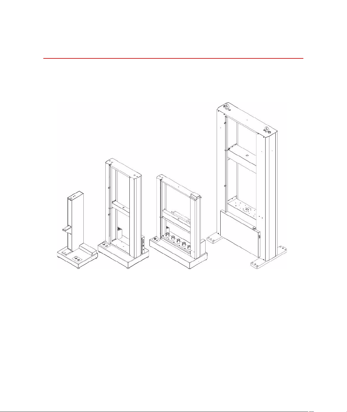
Description
1 kN and 2 kN 2 kN EL High-Speed and
5 kN through 50 kN
100 kN through 300 kN50 kN W and
50 kN W Mulihead (shown)
Description
Every MTS Insight material testing system is comprised of a load frame,
electronic frame controller, and TestWorks
®
software. The following figure
shows the external features of the various MTS Insight load frames.
Introduction
18
The personal computer is also an integral part of the system. It runs
TestWorks software which provides full machine control, data acquisition
and management, and advanced data analysis and presentation. MTS has
minimized the amount of custom electronics required for your system,
thereby making it flexible and reliable. This is done by connecting the frame
and the computer via standard USB 2.0 connectors.
Insight Material Testing System
Page 19

The load frame has a rectangular shape and includes a base unit and one or
two vertical columns. The two column models have a fixed upper transverse
member. The moving crosshead is driven by precision ball screws on the
load frame. The crosshead is coupled to the ball screw(s) with high-strength,
precision ball nuts and rides on the ball bearings. This configuration is very
efficient in minimizing friction and wear. The ball screws are anti-backlash.
This feature removes the backlash so that position can be measured with
increased accuracy over nonpreloaded ball screws.
The screws are driven by a series of pulleys and belts which in turn are
driven by a precision dc servo motor on the MTS Insight 1 through MTS
Insight 50 models and an ac brushless motor on the higher force models. The
ball screw is connected to an optical encoder for precise position and
velocity control.
Frame controller The frame controller is responsible for the following:
• Provides main data and signal processing power
• Detects the activation of limit switches
• Provides the interface between the software (computer) and the
frame
• Provides digital servo control—for speed and position accuracy
• Responsible for self-ID load cell and frame
• Handset interface
• Programmable, 1000 Hz maximum, data acquisition rate
• Management of frame power
Description
Software TestWorks 4 is a versatile software program offering you a host of features
that will make the material testing process fast and easy to use. The software
has various method templates available. The method templates in the
General Testing Package provide a starting point in configuring test methods
that conform with your testing needs. The General Testing Package is
separated into 4 specific testing categories.
• MTS Tensile
• MTS Compression
• MTS Flex
• MTS Peel-Tear
Many additional features can be purchased to meet your company’s specific
needs. Some of these features might already be part of the system you
ordered, or they can be added to your system as your requirements change.
Refer to the TestWorks manual for additional information.
Insight Material Testing System Introduction
19
Page 20

Specifications
Specifications
This section provides general specifications for the MTS Insight Material
Testing System frames and illustrations of the crosshead and baseplate
threaded hole patterns for mounting fixtures.
Note At the time of this printing, some specifications have not been tested
and calculated specifications are provided in the following tables.
Consequently, specifications are subject to change without notice.
Contact MTS for verification if critical specifications.
General Specifications
The following specifications are for all MTS Insight frames. Specifications
for the specific models and in the following tables.
Parameter Specification
Environmental
For indoor use only
20
Introduction
Power
Temperature
Relative humidity
Altitude
Insulation over voltage
Pollution degree
5 to 40 °C
10 to 85%, noncondensing
For use at altitudes up to 2000 m
(6500 ft)
Category II
2
Insight Material Testing System
Page 21

Specifications
Model Specifications
Specifications for MTS Insight 1 and MTS Insight 1 EL
Specifications MTS Insight 1 MTS Insight 1 EL
Force Capacity 1 kN (225 lbf) 1 kN (225 lbf)
Minimum Test S peed 0.001 mm/min. (0.00004 in./min.) 0.001 mm/min (0.00004 in./min.)
Maximum Test Speed 1500 mm/min. (59 in./min.) 1500 mm/min. (59 in./min.)
Force Capacity
@ max. test speed
Maximum Test Speed
@rated force capacity
Crosshead Return Speed 1500 mm/min. (59 in./min.) 1500 mm/min. (59 in./min.)
Vertical Test Space
(crosshead travel)
Horizontal Test Space
(centerline to rear column)
Position Resolution 0.001 mm (0.00004 in.) 0.001 mm (0.00004 in.)
Position Accuracy 0.01 mm (0.0004 in.) 0.01 mm (0.0004 in.)
Speed Accuracy % of set speed
Motor Type Precision DC Servo Motor Precision DC Servo Motor
Drive System Type DC 4 Quadrant Motor Drive DC 4 Quadrant Motor Drive
Position Measurement Optical Encoder Optical Encoder
Ball Screw Type Anti-backlash Anti-backlash
Height/Width/Depth 1136 X 490 X 450 mm
Weight 50 kg (110 lb) 55 kg (122 lb)
Power 5/3 Amps
1 kN (225 lbf) 1 kN (225 lbf)
1500 mm/min. (59 in./min.) 1500 mm/min. (59 in./min.)
750 mm (29.5 in.) 1000 mm (39.5 in.)
104 mm (4.1 in.) 104 mm (4.1 in.)
±0.05 ±0.05
1394 X 490 X 450 mm
(45 X 19 X 18 in.)
120/220-240 Vac
50/60 Hz
Single phase
(55 X 19 X 18 in.)
5/3 Amps
120/220-240 Vac
50/60 Hz
Single phase
Insight Material Testing System Introduction
21
Page 22

Specifications
Specifications for MTS Insight 2 and MTS Insight 2 EL
Specifications MTS Insight 2 MTS Insight 2 EL
Force Capacity 2 kN (450 lbf) 2 kN (450 lbf)
Minimum Test S peed 0.001 mm/min. (0.00004 in./min.) 0.001 mm/min. (0.00004 in./min.)
Maximum Test Speed 1000 mm/min. (39.4 in./min.) 1000 mm/min. (39.4 in./min.)
Force Capacity
@ max. test speed
Maximum Test Speed
@rated force capacity
Crosshead Return Speed 1500 mm/min. (59 in./min.) 1500 mm/min. (59 in./min.)
Vertical Test Space
(crosshead travel)
Horizontal Test Space
(centerline to rear column)
Position Resolution 0.001 mm (0.00004 in.) 0.001 mm (0.00004 in.)
Position Accuracy 0.01 mm (0.0004 in.) 0.01 mm (0.0004 in.)
Speed Accuracy % of set speed
Motor Type Precision DC Servo Motor Precision DC Servo Motor
Drive System Type DC 4 Quadrant Motor Drive DC 4 Quadrant Motor Drive
Position Measurement Optical Encoder Optical Encoder
Ball Screw Type Anti-backlash Anti-backlash
Height/Width/Depth 1136 X 490 X 450 mm
Weight 50 kg (110 lb) 55 kg (119 lb)
Power 5/3 Amps
2 kN (450 lbf) 2 kN (450 lbf)
1000 mm/min. (39.4 in./min.) 1000 mm/min. (39.4 in./min.)
750 mm (29.5 in.) 1000 mm (39.5 in.)
104 mm (4.1 in.) 104 mm (4.1 in.)
±0.05 ±0.05
1394 X 490 X 450 mm
(45 X 19 X 18 in.)
120/220-240 Vac
50/60 Hz
Single phase
(55 X 19 X 18 in.)
5/3 Amps
120/220-240 Vac
50/60 Hz
Single phase
22
Introduction
Insight Material Testing System
Page 23

Specifications
Specifications for MTS Insight 2 EL High-Speed
Specifications MTS Insight 2 EL High Speed
Force Capacity 2 kN (450 lbf)
Minimum Test S peed 0.003 mm/min. (0.00012 in./min.)
Maximum Test Speed 2540 mm/min. (100 in./min.)
Force Capacity
@ max. test speed
Maximum Test Speed
@rated force capacity
Crosshead Return Speed 2540 mm/min. (100 in./min.)
Vertical Test Space
(crosshead travel)
Horizontal Test Space
(space between columns)
Position Resolution 0.003 mm (0.00012 in.)
Position Accuracy 0.03 mm (0.0012 in.)
Speed Accuracy % of set speed
Motor Type Precision DC Servo Motor
Drive System Type DC 4 Quadrant Motor Drive
Position Measurement Optical Encoder
Ball Screw Type Anti-backlash
Guide Columns Two
Height/Width/Depth 19 00 X 650 X 450 mm
Weight 123 kg (261 lb)
Power 5/3 Amps
2 kN (450 lbf)
2540 mm/min. (100 in./min.)
1400 mm (55 in.)
405 mm (15.9 in.)
±0.05
(74.75 X 26 X 18 in.)
120/220-240 Vac
50/60 Hz
Single phase
Insight Material Testing System Introduction
23
Page 24

Specifications
Specifications for MTS Insight 5 and MTS Insight 5 EL
Specifications MTS Insight 5 MTS Insight 5 EL
Force Capacity 5 kN (1125 lbf) 5 kN (1125 lbf)
Minimum Test S peed 0.001 mm/min. (0.00004 in./min.) 0.001 mm/min. (0.00004 in./min.)
Maximum Test Speed 1000 mm/min. (39 in./min.) 1000 mm/min. (39 in./min.)
Force Capacity
@ max. test speed
Maximum Test Speed
@rated force capacity
Crosshead Return Speed 1000 mm/min. (59 in./min.) 1000 mm/min. (59 in./min.)
Vertical Test Space
(crosshead travel)
Horizontal Test Space
(space between columns)
Position Resolution 0.001 mm (0.00004 in.) 0.001 mm (0.00004 in.)
Position Accuracy 0.01 mm (0.0004 in.) 0.01 mm (0.0004 in.)
Speed Accuracy % of set speed
Motor Type Precision DC Servo Motor Precision DC Servo Motor
Drive System Type DC 4 Quadrant Motor Drive DC 4 Quadrant Motor Drive
Position Measurement Optical Encoder Optical Encoder
Ball Screw Type Anti-backlash Anti-backlash
Guide Columns Two Two
Height/Width/Depth 1600 X 650 X 450 mm
Weight 115 kg (255 lb) 123 kg (271 lb)
Power 5/3 Amps
5 kN (1125 lbf) 5 kN (1125 lbf)
1000 mm/min. (39 in./min.) 1000 mm/min. (39 in./min.)
1100 mm (43 in.) 1400 mm (55 in.)
405 mm (15.9 in.) 405 mm (15.9 in.)
±0.05 ±0.05
1900 X 650 X 450 mm
(63 X 25.6 X 17.7 in.)
120/220-240 Vac
50/60 Hz
Single phase
(75 X 26 X 18 in.)
5/3 Amps
120/220-240 Vac
50/60 Hz
Single phase
24
Introduction
Insight Material Testing System
Page 25

Specifications for MTS Insight 10
Specifications MTS Insight 10
Force Capacity 10 kN (2250 lbf)
Minimum Test Speed 0.001 mm/min. (0.00004 in./min.)
Maximum Test Speed 1000 mm/min. (39 in./min.)
Force Capacity
@ max. test speed
Maximum Test Speed
@rated force capacity
Crosshead Return Speed 1000 mm/min. (39 in./min.)
Vertical Test Space
(crosshead travel)
Horizontal Test Space
(space between columns)
Position Resolution 0.001 mm (0.00004 in.)
Position Accuracy 0.01 mm (0.0004 in.)
Speed Accuracy % of set speed
Motor Type Precision DC Servo Motor
Drive System Type DC 4 Quadrant Motor Drive
Position Measurement Optical Encoder
Ball Screw Type Anti-backlash
Guide Columns Two
Height/Width/Depth 1600 X 650 X 450 mm
Weight 1 15 kg (255 lb)
Power 5/3 Amps
5 kN (1125 lbf)
500 mm/min. (19.7 in./min.)
1100 mm (43 in.)
405 mm (15.9 in.)
±0.05
(63 X 25.6 X 17.7 in.)
120/220-240 Vac
50/60 Hz
Single phase
Specifications
Insight Material Testing System Introduction
25
Page 26

Specifications
Specifications for MTS Insight 30 and MTS Insight 30 EL
Specifications MTS Insight 30 MTS Insight 30 EL
Force Capacity 30 kN (6750 lbf) 30 kN (6750 lbf)
Minimum Test S peed 0.001 mm/min. (0.00004 in./min.) 0.001 mm/min. (0.00004 in./min.)
Maximum Test Speed 500 mm/min. (19.7 in./min.) 500 mm/min. (19.7 in./min.)
Force Capacity
@ max. test speed
Maximum Test Speed
@rated force capacity
Crosshead Return Speed 500 mm/min. (20 in./min.) 500 mm/min. (20 in./min.)
Vertical Test Space
(crosshead travel)
Horizontal Test Space
(space between columns)
Position Resolution 0.001 mm (0.00004 in.) 0.001 mm (0.00004 in.)
Position Accuracy 0.01 mm (0.0004 in.) 0.01 mm (0.0004 in.)
Speed Accuracy % of set speed
Motor Type Precision DC Servo Motor Precision DC Servo Motor
Drive System Type DC 4 Quadrant Motor Drive DC 4 Quadrant Motor Drive
Position Measurement Optical Encoder Optical Encoder
Ball Screw Type Anti-backlash Anti-backlash
Guide Columns Two Two
Height/Width/Depth 1619 X 720 X 500 mm
Weight 180 kg (397 lb) 191 kg (422 lb)
Power 5/3 Amps
25 kN (5625 lbf) 25 kN (5625 lbf)
500 mm/min. (19.7 in./min.) 500 mm/min. (19.7 in./min.)
1100 mm (43 in.) 1400 mm (55 in.)
405 mm (15.9 in.) 405 mm (15.9 in.)
±0.05 ±0.05
1913 X 720 X 500 mm
(63.7 X 28.3 X 19.7 in.)
120/220-240 Vac
50/60 Hz
Single phase
(75.4 X 29 X 20 in.)
5/3 Amps
120/220-240 Vac
50/60 Hz
Single phase
26
Introduction
Insight Material Testing System
Page 27

Specifications for MTS Insight 50
Specifications MTS Insight 50
Force Capacity 50 KN (11250 lbf)
Minimum Test Speed 0.001 mm/min. (0.00004 in./min.)
Maximum Test S peed 500 mm/min. (19.7 in./min.)
Force Capacity
@ max. test speed
Maximum Test S peed
@rated force capacity
Crosshead Return Speed 500 mm/min. (20 in./min.)
Vertical Test Space
(crosshead travel)
Horizontal Test Space
(space between columns)
Position Resolution 0.001 mm (0.00004 in.)
Position Accuracy 0.01 mm (0.0004 in)
Speed Accuracy % of set speed
Motor Ty pe Precision DC Servo Motor
Drive System Type DC 4 Quadrant Motor Drive
Position Measurement Optical Encoder
Ball Screw Type Anti-backlash
Guide Columns Two
Height/Width/Depth 1613 X 720 X 500 mm
Weight 180 kg (397 lb)
Power 5/3 Amps
25 KN (5625 lbf)
250 mm/min. (9.8 in./min.)
1100 mm (43 in.)
405 mm (15.9 in.)
±0.05
(63.5 X 28.3 X 19.7 in.)
120/220-240 Vac
50/60 Hz
Single phase
Specifications
Insight Material Testing System Introduction
27
Page 28

Specifications
Specifications for MTS Insight 50 W
Specifications MTS Insight 50 Wide
Force Capacity 50 KN (11250 lbf)
Minimum Test Speed 0.001 mm/min. (0.00004 in./min.)
Maximum Test S peed 500 mm/min. (19.7 in./min.)
Force Capacity
@ max. test speed
Maximum Test S peed
@rated force capacity
Crosshead Return Speed 500 mm/min. (20 in./min.)
Vertical Test Space
(crosshead travel)
Horizontal Test Space
(space between columns)
Position Resolution 0.001 mm (0.00004 in.)
Position Accuracy 0.01 mm (0.0004 in)
Speed Accuracy % of set speed
Motor Ty pe Precision DC Servo Motor
Drive System Type DC 4 Quadrant Motor Drive
Position Measurement Optical Encoder
Ball Screw Type Anti-backlash
Guide Columns Two
Height/Width/Depth 1629 X 1145 X 500 mm
Weight 296 kg (653 lb)
Power 5/3 Amps
25 KN (5625 lbf)
250 mm/min. (9.8 in./min.)
1100 mm (43 in.)
835 mm (33 in.)
±0.05
(64.1 X 45 X 20 in.)
120/220-240 Vac
50/60 Hz
Single phase
28
Introduction
Insight Material Testing System
Page 29

Specifications for MTS Insight 50 W Multihead
Specifications MTS Insight 50 Wide
Force Capacity 50 KN (11250 lbf)
Minimum Test Speed 0.001 mm/min. (0.00004 in./min.)
Maximum Test S peed 500 mm/min. (19.7 in./min.)
Force Capacity
@ max. test speed
Maximum Test S peed
@rated force capacity
Crosshead Return Speed 500 mm/min. (20 in./min.)
Vertical Test Space
(crosshead travel)
Horizontal Test Space
(between baseplate adapter
centerlines)
Position Resolution 0.001 mm (0.00004 in.)
Position Accuracy 0.01 mm (0.0004 in)
Speed Accuracy % of set speed
Motor Ty pe Precision DC Servo Motor
Drive System Type DC 4 Quadrant Motor Drive
Position Measurement Optical Encoder
Ball Screw Type Anti-backlash
Guide Columns Two
Height/Width/Depth 1629 X 1145 X 500 mm
Weight 350 kg (772 lb)
Power 5/3 Amps
25 KN (5625 lbf)
250 mm/min. (9.8 in./min.)
1016 mm (40 in.)
155.5 mm (6.125 in.)
±0.05
(64.1 X 45 X 20 in.)
120/220-240 Vac
50/60 Hz
Single phase
Specifications
Insight Material Testing System Introduction
29
Page 30

Specifications
Specifications for MTS Insight 100
Specifications MTS Insight 100
Force Capacity 100 kN (22500 lbf)
Minimum Test Speed 0.01 mm/min. (0.0004 in./min.)
Maximum Test S peed 500 mm/min. (19.7 in./min.)
Force Capacity
@ max. test speed
Maximum Test S peed
@rated force capacity
Crosshead Return Speed 500 mm/min. (19.7 in./min.)
Vertical Test Space
(crosshead travel)
Horizontal Test Space
(space between columns)
Position Resolution 0.001 mm (0.00004 in.)
Position Accuracy 0.01 mm (0.0004 in.)
Speed Accuracy % of set speed
Motor Ty pe AC Brushless
Drive System Type Single-phase Sinusoidal
Position Measurement Optical Encoder
Ball Screw Type Anti-backlash
Guide Columns Two
Height/Width/Depth 2440 X 1133 X 685 mm
Weight 750 kg (1655 lb)
Power Max. current 10 Amps
50 kN (11250 lbf)
500 mm/min. (19.7 in./min.)
1200 mm (47.3 in.)
650 mm (25.6 in.)
±0.05
(96 X 44.6 X 27 in.)
230 Vac
50/60 Hz
Single phase
30
Introduction
Insight Material Testing System
Page 31

Specifications for MTS Insight 150
Specifications MTS Insight 150
Force Capacity 150 kN (33750 lbf)
Minimum Test Speed 0.01 mm/min. (0.0004 in./min.)
Maximum Test S peed 500 mm/min. (19.7 in./min.)
Force Capacity
@ max. test speed
Maximum Test S peed
@rated force capacity
Crosshead Return Speed 500 mm/min. (19.7 in./min.)
Vertical Test Space
(crosshead travel)
Horizontal Test Space
(space between columns)
Position Resolution 0.001 mm (0.00004 in.)
Position Accuracy 0.01 mm (0.0004 in.)
Speed Accuracy % of set speed
Motor Ty pe AC Brushless
Drive System Type 3-phase Sinusoidal
Position Measurement Optical Encoder
Ball Screw Type Anti-backlash
Guide Columns Two
Height/Width/Depth 2440 X 1133 X 685 mm
Weight 970 kg (2140 lb)
Power Max. current 18 Amps
150 kN (33750 lbf)
500 mm/min. (19.7 in./min.)
1200 mm (47.3 in.)
650 mm (25.6 in.)
±0.05
(96 X 44.6 X 27 in.)
400 Vac
50/60 Hz
Three phase
Specifications
Insight Material Testing System Introduction
31
Page 32

Specifications
Specifications for MTS Insight 200
Specifications MTS Insight 200
Force Capacity 200 kN (45000 lbf)
Minimum Test Speed 0.01 mm/min. (0.0004 in./min.)
Maximum Test S peed 500 mm/min. (19.7 in./min.)
Force Capacity
@ max. test speed
Maximum Test S peed
@rated force capacity
Crosshead Return Speed 500 mm/min. (19.7 in./min.)
Vertical Test Space
(crosshead travel)
Horizontal Test Space
(space between columns)
Position Resolution 0.001 mm (0.00004 in.)
Position Accuracy 0.01 mm (0.0004 in.)
Speed Accuracy % of set speed
Motor Ty pe AC Brushless
Drive System Type 3-phase Sinusoidal
Position Measurement Optical Encoder
Ball Screw Type Anti-backlash
Guide Columns Two
Height/Width/Depth 2440 X 1133 X 685 mm
Weight 970 kg (2140 lb)
Power Max. current 20 Amps
200 kN (45000 lbf)
500 mm/min. (19.7 in./min.)
1200 mm (47.3 in.)
650 mm (25.6 in.)
±0.05
(96 X 44.6 X 27 in.)
400 Vac
50/60 Hz
Three phase
32
Introduction
Insight Material Testing System
Page 33

Specifications for MTS Insight 300
Specifications MTS Insight 300
Force Capacity 300 kN (67500 lbf)
Minimum Test Speed 0.01 mm/min. (0.0004 in./min.)
Maximum Test S peed 500 mm/min. (19.7 in./min.)
Force Capacity
@ max. test speed
Maximum Test S peed
@rated force capacity
Crosshead Return Speed 500 mm/min. (19.7 in./min.)
Vertical Test Space
(crosshead travel)
Horizontal Test Space
(space between columns)
Position Resolution 0.001 mm (0.00004 in.)
Position Accuracy 0.01 mm (0.0004 in.)
Speed Accuracy % of set speed ±0.05
Motor Ty pe AC Brushless
Drive System Type 3-phase Sinusoidal
Position Measurement Optical Encoder
Ball Screw Type Anti-backlash
Guide Columns Two
Height/Width/Depth 2440 X 1133 X 685 mm
Weight 1050 kg (2315 lb)
Power Max. current 32 Amps
300 kN (67500 lbf)
500 mm/min. (19.7 in./min.)
1150 mm (45.3 in.)
650 mm (25.6 in.)
(96 X 44.6 X 27 in.)
400 Vac
50/60 Hz
Three phase
Specifications
Insight Material Testing System Introduction
33
Page 34

Specifications
Crosshead Detail
The crosshead has a single hole drilled through for mounting loadcells,
alignment fixtures, grips, etc.
34
Introduction
Insight Material Testing System
Page 35

Baseplate Detail
The baseplate has various patterns of threaded holes for mounting fixtures.
Specifications
Insight Material Testing System Introduction
35
Page 36

Specifications
50 kN W Multihead
36
Introduction
Insight Material Testing System
Page 37

Model Baseplate Thickness
mm in.
1 kN 19 0.7
2 kN 19 0.7
2 kN EL HS 25 1.0
5 kN 25 1.0
10 kN 25 1.0
30 kN 25 1.0
50 kN 25 1.0
50 kN W 50 2.0
50 kN W Miltihead 50 2.0
100 kN 140 5.5
150 kN 152 6.0
Specifications
200 kN 152 6.0
300 kN 178 7.0
Insight Material Testing System Introduction
37
Page 38

Specifications
38
Introduction
Insight Material Testing System
Page 39

Installation
WARNING
This section provides guidelines for moving and installing your MTS Insight
material testing system.
Unless otherwise specified, it is your responsibility to off-load, unpack, and
move the equipment to the final location on your premises. This includes
insurance and safety responsibility.
Before moving the machine from the receiving area to its final location, be
sure to check the dimensions of all doors and passages through which the
machine will travel. Refer to the specification tables in the Introduction
section of this manual for dimensions.
Contents Moving the 1 kN and 2 kN Frames 40
Moving the 5 kN and Higher Frames 42
Machine location and ventilation 43
Controller Connections 44
Connecting the main power 44
Installing cables 50
The MTS Insight frames are heavy.
Moving the frame using improper procedures can injure personnel (for
example strained muscles and back injuries) or damage the frame.
When lifting the frame, take the appropriate precautions to prevent injuries to
yourself. Moving and positioning the MTS Insight frame must be performed
by qualified personnel only.
MTS Insight frames weigh from 50 kg (110 lb) to 1050 kg (2315 lb). Other
apparatus such as the pallet, packaging, and accessories add to the overall
weight. If you have any questions, call MTS.
Insight Material Testing System Installation
39
Page 40

Moving the 1 kN and 2 kN Frames
CAUTION
Center on pallet
jack for maximum
stability.
Push or pull at
the top.
Do not push
the sides.
Moving the 1 kN and 2 kN Frames
Pallet jacks rated at or above the weight of the machine should be used; refer
to the tables in the Specifications section for frame weights.
When tipping the frame, push or pull only at the top. Do not push the
frame at the sides.
Pushing on the side of the frame can damage the sheet metal.
It is recommended that the frame be moved by at least two people: one to tip
the frame and one to position the pallet jack. Once the frame is on the pallet
jack, one person should operate and move the pallet jack while the other one
steadies the frame. It is also recommended to put something on the fo rks to
minimize the chance of damage to the frame; for example, a piece of
cardboard or carpet scrap.
Tip the frame by blocking the bottom with your foot to keep it from sliding,
then pull the top of the frame towards you to tip it. Do not push on the sheet
metal sides. Tip the frame only as far as necessary to gain clearance to
position the pallet jack underneath; do not tip more than 10
° in any direction.
40
Installation
Insight Material Testing System
Page 41

Moving the 1 kN and 2 kN Frames
WARNING
Once the frame is tipped, push the pallet jack under the frame then return the
frame to the upright position resting on top of the pallet jack. Position the
frame on the pallet jack such that it is centered and stable.
With one person holding onto the frame and one person operating the pallet
jack, move the frame to its final position. Tip the frame as you did when you
put it on the pallet jack and pull the pallet jack out from under the frame.
Carefully lower the frame back to its normal upright position.
The MTS Insight frames are heavy.
Moving the frame using improper procedures can injure personnel (for
example strained muscles and back injuries) or damage the frame.
When lifting the frame, take the appropriate precautions to prevent injuries to
yourself. Moving and positioning the MTS Insight frame must be performed
by qualified personnel only.
In some cases, the final frame position will be on top of a table. Make sure
you have enough help or appropriate lifting devices.
Ensure any table upon which the frame is placed is sturdy , level, and capable
of supporting the weight of the machine.
Insight Material Testing System Installation
41
Page 42

Moving the 5 kN and Higher Frames
CAUTION
Moving the 5 kN and Higher Frames
MTS Insight load frames of 5 kN and higher should only be moved using a
forklift rated at or above the weight of the machine; refer to the tables in the
Specifications section for frame weights.
Improper lifting can damage the frame.
When lifting and moving the frame, follow these guidelines to minimize the
chance of equipment damage:
• Do not lift by the top plate that joins the ends of the ball screws and side
covers.
• Do not lift the machine by the side covers. The weight of the machine will
damage the side covers.
• Do not lift by the ball screws.
On the forklift, adjust the distance between the forks such that they will fit
between the columns of the frame. Position the forks on the forklift as shown
in the following illustration. Allow enough room between the frame and the
forklift to allow a slight tilt once the frame is off the ground. (Weight
distribution front to back is not perfectly balanced and the frame will tilt
slightly as it is lifted.) It is also recommended to put something on the forks
to minimize the chance of damage to the frame; for example, a piece of
cardboard or carpet scrap.
42
Installation
Lift the frame only as high as necessary to allow sufficient ground clearance
on the way to its final position. Move the frame to its final position and
slowly lower onto the ground.
Insight Material Testing System
Page 43

Machine location and ventilation
Machine location and ventilation
T o ensure proper ventilation, locate the load frame approximately 300 mm
(12 inches) from adjacent walls and equipment. Allow approximately 1 m
(3 feet) behind the equipment for service access. Do not block the vent
holes in the bottom of the machine.
For comfortable working conditions and proper equipment operation, heat
dissipation of the equipment must be considered in providing adequate
heating or air conditioning in the laboratory area. Heat dissipation can be
approximated by summing the heat losses going into a room (1 kVA is
equivalent to 860 kcal/hr [3,400 Btu/hr]) and the gains from other sources
such as furnaces and personnel.
Insight Material Testing System Installation
43
Page 44

Controller Connections
CAUTION
Wall outlet
(line voltage)
Transformer
Frame
connection
Controller Connections
Connecting the main power
1 kN through 50 kN MTS Insight frames rated 50 kN or less are supplied with a transformer that
reduces the voltage for frame operation; see the following illustration.
Do not connect the frame directly to the main AC line voltage.
Connecting the frame directly to the main AC line voltage will cause
equipment damage.
Installation
44
In North America for 220 V operation, the transformer will be equipped with
a 3-prong twist-lock plug (NEMA L6-20P). This plug must be used with a
matching locking receptacle (NEMA L6-20R) to ensure proper grounding. If
you do not have a receptacle of this type available, contact a qualified
electrician to make the connection.
In Europe for 220-240 V operation, the unit will be equipped with a plug of
type CEE 7/7 (Schuko). If you do not have a mating receptacle available,
contact a qualified electrician to make the connection.
Insight Material Testing System
Page 45

Controller Connections
To wall outlet
(line voltage)
Additional power for
50 kN W Multihead
For 50 kN W Multihead frame, the National Instruments power suppley also
needs to be connect to main power.
Insight Material Testing System Installation
45
Page 46

Controller Connections
100 kN through 300 kN Important Local electrical codes supersede any information found in
this manual.
Electrical connections must be made by qualified personnel and is their
responsibility for using the proper power disconnect along with the correct
size and type of wire and conduit that conforms to all their local electrical
codes when connecting the machine and transformer to the buildings main
power.
Wire sizes The minimum wire gauge inside conduit requirements are:
• MTS Insight 100 – 14 AWG
• MTS Insight 150 – 12 AWG
• MTS Insight 200 – 10 AWG
• MTS Insight 300 – 8 AWG
Ground wire needs to be the same gauge wire or larger than those listed
above for the associated frame size.
Electrical Disconnect The electrical box must have a power disconnect switch that is easy to
operate and easy to reach. It must also meet IEC 60947-1 and IEC 60947-3
standards.
46
Installation
Recommended circuit breakers would be ones that are of the thermal
magnetic type with characteristics suitable for large inductive loads (D-type
trip characteristic). If fuses are used it is recommended that they are of the
time delay type with dual elements. These recommendations should be
followed to avoid nuisance tripping.
For the Insight 200 and 300 the electrical box over current device must be
Branch circuit rated.
Insight Material Testing System
Page 47

Controller Connections
Customer wiring
connections
Customer wiring
connections
MTS Insight 100 Following shows connections to MTS Insight 100 load frames.
MTS Insight 150, 200
and 300
Following shows connections to MTS Insight 150, 200, and 300 load frames.
Insight Material Testing System Installation
47
Page 48

Controller Connections
Transformer Requirements for MTS Insight 150, 200 and 300 Machines
Important Remember to verify local codes, voltages and frequencies
before ordering transformer.
Following are the minimum requirements for transformers for the MTS
Insight 150, 200, and 300 load frames.
• Isolation Type Transformer (Electrical isolation between input and
output).
• 3-phase input and output.
• Wye output with neutral connection at 400 VAC.
• Equi-potential between each output phase and earth/ground.
• Ambient operating temperature from 5 deg C to 40 deg C.
• Temperature rise 150 deg C maximum.
• Insulation class 200 deg C minimum.
• Electrostatic Shield.
Additional
considerations
Typical Power in
Selected Areas
• UL Listed along with CE and CSA/CUL or equivalent depending
country.
• Floor standing.
• NEMA 2 or better enclosure.
• Harmonic Factor can be 0.
• Maximum sound level 45 dB per ANSI Standard C89.2.
United States - Voltage and Frequency
480 VAC @ 60 Hz
Canada - Voltage and Frequency
600 VAC @ 60 Hz
Europe - Voltage and Frequency
400 VAC @ 50 Hz
48
Installation
Insight Material Testing System
Page 49

Machine Specific
Requirements
Insight 150 • Nominal output power 12 kVA.
Insight 200 • Nominal output power 16 kVA.
Insight 300 • Nominal output power 24 kVA.
Controller Connections
• Nominal output phase current 15 A maximum.
• Peak output phase current 30 A maximum for 1.25 seconds
• Nominal output phase current 20 A maximum.
• Peak output phase current 40 A maximum for 1.25 seconds
• Nominal output phase current 30 A maximum.
• Peak output phase current 60 A maximum for 1.25 seconds
Insight Material Testing System Installation
49
Page 50

Controller Connections
CAUTION
Installing cables
Exercise care when connecting cables. Ensure that you are using the correct
cables and that all connections are secure. When you are finished, doublecheck to ensure that all components are connected properly.
T urn the power off before connecting cables.
Connecting cables with power applied can cause damage to the equipment.
Controller Connectors
J1 USB This is a standard USB 2.0 connector that accepts a USB-B cable connector
and connects to the computer. This provides a communications interface
between TestWorks on the PC and the controller. This is used to allow
TestWorks, or other software, to change settings in the controller. It also
allows Tes tWorks to receive data from the controller.
50
Installation
Insight Material Testing System
Page 51

Controller Connections
J2 Handset This is intended to interface to the handset. Specifics for this connector are:
• 12 V output power with 200 mA current limit
• RS422 driver (differential)
• RS422 receiver (differential)
• Interlock input. Handset shorts between INTLK+ and INTLK- when it
is connected.
• 8-pin RJ-45 connector
Pin Signal
1Transmit +
2Transmit 3 +12V
4INTLK+
5INTLK6Analog GND
7 Receive +
8 Receive -
Insight Material Testing System Installation
51
Page 52

Controller Connections
J3 Interlock This is intended to connect to a test area enclosure switch that opens when
J4 Encoder This connector is intended for an encoder based extensometer. Specifics for
the door is opened. If not used, a jumper plug (p/n 049-635-901) must be
installed. If you are building a cable, maximum length is 30.48 m (100 ft)
with 24 gauge wire. Switch should be wired normally closed, such that when
the switch opens, an interlock is generated.
this connector: are
• Power: +5 V +/- 0.25 V at 100 mA max
• Signals: Quadrature A and B with index I
• Logic: Differential receivers (can connect single ended)
• Maximum Rate: 100,000 lines/sec = 400,000 counts/sec
52
Installation
Pin assignment is as follows:
Pin Signal
1 TEDS data
2A+
3A4+5V
5I+
6I7Analog GND
8B+
9B10 TEDS ground
Insight Material Testing System
Page 53

Controller Connections
J5 Digital I/O Digital I/O signals include three optically isolated inputs, three optically
isolated outputs, and 12V power. Functions of each digital input or output
are software selectable. A typical example might be connecting an external
switch; see “Additional Digital I/O Information” on page 73. Pin assignment
is as follows:
Pin Signal
1 In 1+
2 In 2+
3 In 3+
4 Out 1+
5 Out 2+
6 Out 3+
7 No Contact
8+12V
9 In 110 In 211 In 312 Out 113 Out 214 Out 315 Analog GND
Insight Material Testing System Installation
53
Page 54

Controller Connections
J6 and J7
Monitor
J8 and J9 DC
Conditioner
Two Monitor connectors are provided. There are several possible uses for
analog monitor outputs: external data acquisition, tuning, troubleshooting,
etc. For tuning, it is desirable to monitor command and feedback, or
command and error, simultaneously while changing the controller
parameters. Therefore, two monitor outputs are provided. Specifics for these
connectors are:
• Analog +/-10.5 V
• Calibrated to +/-10 V
• 16-bit resolution minimum
• BNC connectors
Note The load cell is mounted to the crosshead and its wiring is internal to
the frame, thus its connector is not on the rear panel.
Two DC Conditioner connectors are provided. Th e two appl ication specific
transducers might be biaxial strain gage base extensometers. With external
completion resistors, the DC conditioners could be used with quarter bridge
strain gages. Pin assignment is as follows:
Pin Signal
1TEDS data
2 EX+
54
Installation
3 EX4FB5 RCAL1 (FBR+)
6 RCAL2 (FBR-)
7FB+
8 EXS9 EXS+
10 TEDS ground
Insight Material Testing System
Page 55

Crosshead load cell
Load cell connector
(shown on an Insight 50)
connector
Controller Connections
A connector (D-15) for the load cell is provided under the crosshead on one
of the columns. Pin assignment is as follows:
Pin Signal
1 EX+
2 EX3 No Contact
4FB+
5FB6 No Contact
7SHIELD
8TEDS+
9 No Contact
10 EXS+
11 No Contact
12 RCAL1 (FBR+)
13 RCAL2 (FBR-)
14 TEDS-
Insight Material Testing System Installation
15 EXS-
55
Page 56

Controller Connections
56
Installation
Insight Material Testing System
Page 57

Operation
CAUTION
CAUTION
CAUTION
Contents Hazard Icons 58
This section describes the actions performed during normal, day-today operation of the MTS Insight frame. For information on using the
MTS Insight frame in actual testing, refer to the TestWorks software
manual.
Main Power Switch (I/O) and E-Stop 59
Travel Limit Switches (Physical Limits) 60
Crush Zone Hazards 62
Fixture Mounting 63
Load Cell Mounting 64
Handset Control 68
Do not operate the MTS Insight test frame without the side covers and
bellows in place.
Operating the machine without side covers or bellows in place can expose
the operator to moving parts that could cause injury if contact is made.
Keep the area clean.
Sample debris can enter the side covers and puncture bellows causing erratic
machine operation.
Damaged bellows should be replaced before operating the MTS Insight Test
Frame.
Users should be aware of the potential of material fragments puncturing the
bellows and damaging the ball screw; user needs to be aware of the material
properties and the hazards generated by the materials during testing. Refer to
“General cleaning” on page 71.
Keep the testing area secure.
Only qualified, trained personnel should be allowed to operate the machine.
Keep bystanders away during machine operation.
Insight Material Testing System Operation
57
Page 58

Hazard Icons
Hazard Icons
The following hazard icons are located on the MTS Insight Test Frame.
Additional icons can also be attached to the frame that are explained in the
Safety manual (MTS part number 100003805); refer to the Safety Manual
for additional information.
Moving parts present
Flying objects
Read and understand
manuals
Projectile hazard
WEEE
Operation
58
The Waste Electrical and Electronic Equipment (WEEE) symbol ( )
means that the controller and its electronic parts must not be disposed of as
unsorted municipal waste. Proper disposal is required by approved electronic
waste collection agencies. Customers in the EC region who desire to return
an end-of-life controller and its electronic parts are encouraged to contact
your local MTS Systems Sales/Service Offices for instructions.
Insight Material Testing System
Page 59

Main Power Switch (I/O) and E-Stop
1 - 2 kN 2 EL HS and
5 - 50 kN
100 - 300 kN
Main power and
E-Stop Switches
Main Power Switch (I/O) and E-Stop
The main power switch for the machine is on the base of the frame.
The frame is also equipped with an Emergency Stop button. The
Emergency Stop will cut the power to the motor and should be used for
emergency purposes only.
To shut down the motor power and stop the test program, press the
Emergency Stop button. Twist the switch clockwise to release it. Use the
Emergency Stop button to shut down your test if something unexpected
should happen.
Insight Material Testing System Operation
59
Page 60

Travel Limit Switches (Physical Limits)
1 - 2 kN 2 EL HS and
5 - 300 kN
Limit Switch
Adjustments
Travel Limit Switches (Physical Limits)
The limit switches are located on the crosshead. They are normally closed
and are activated when the limit switch contacts the adjustable limit rod. The
adjustable limit rod can be positioned anywhere along the range of travel to
prevent the crosshead from traveling beyond that point.
Note Always adjust the limits whenever you change grips or fixtures.
Adjustment of the limit switches are similar for both types of machine. The
limit switches are held in position by a locking screw. T o set the limit switch,
unlock by turning the locking screw in an counterclockwise direction and
slide to the required new position. Before locking, allow for the limit switch
striker being in the middle of the crosshead for the single screw machine and
at the bottom of the crosshead for the twin screw machines. To lock limit
switch, rotate locking screw in a clockwise direction. To eliminate slippage
tighten locking screw securely.
Operation
60
Insight Material Testing System
Page 61

Travel Limit Switches (Physical Limits)
When a physical limit is reached there are three ways to get the crosshead
moving again:
• First press Motor Reset in TestWorks 4. Then use the crosshead
capabilities of your software (virtual handset). Move the crosshead
away from the limit until the switch closes and the crosshead can move
in both directions again. See the TestWorks software manual for further
details.
• Manually move the adjustable limit along the range of travel away from
the crosshead until the limit switch is no longer active. Then press
Motor Amp Reset in TestWorks 4 or Handset Enable on the handset.
• If TestWorks 4 is not active, press Handset Enable on the handset. Then
use the manual handset control to move the crosshead until the limit
switch is no longer active.
Insight Material Testing System Operation
61
Page 62

Crush Zone Hazards
Crush
zones
Crush
zones
1 - 2 kN 2 EL HS and 5 - 300 kN
Crush Zone Hazards
It is important to stay clear of any potential crush zones when the
system is operating. Know where the crush zones are in your system
and protect yourself and others from those crush zones with
appropriate safety devices. The following paragraphs describe crush
zones and precautions to take while working around crush zones.
Locations A crush zone exists between the platen and crosshead on load units
where the crosshead and specimen move (both areas are shown).
Precautions Keep clear of any mechanical linkage that moves within a closed area.
If the linkage should move (when the system starts or due to
mechanical failure), very high forces can be present that could pinch,
cut, or crush anything in the path of linkage movement.
Never allow any part of your body to enter the path of machine
movement or to touch moving machinery, linkages, hoses, cables,
specimens, etc. These present serious crush points or pinch points.
Operation
62
Insight Material Testing System
Page 63

Fixture Mounting
Locking
Collar
Mounting Pin
(Clevis Pin Adapter)
Mounting Dowel
(Pin)
Load Frame
Mounting
Adapter
MTS offers a wide variety of fixtures. Mounting these fixtures typically
involves installing the fixture or load cell onto a mounting (clevis pin)
adapter and securing it with a mounting dowel (pin). To further secure a
fixture, some configurations also include locking collars. A typical mounting
configuration is shown in the following illustration.
Fixture Mounting
Insight Material Testing System Operation
63
Page 64

Load Cell Mounting
Cap screw
Washer
Sleeve
Plate assembly
Load cell
1 kN and 2 kN
Load Cell Mounting
Mounting load cells typically involves securing the load cell to the frame via
a threaded bolt along with associated hardware (in most cases a flat washer,
adapter sleeve, and plate assembly). The following illustrations show the
standard mounting configurations. Following the illustration s is a table th at
provides frame size, bolt thread size, and recommended torque value.
Operation
64
Insight Material Testing System
Page 65

Load Cell Mounting
Cap screw
Washer
Sleeve
Plate assembly
Load cell
2 kN EL HS, 5 kN, and 10 kN
or
Cap screw
Washer
Sleeve
Plate assembly
Load cell
30 kN, 50 kN, and 50 kN W
or
Insight Material Testing System Operation
65
Page 66

Load Cell Mounting
Cap screw
Washer
Sleeve
Plate assembly
Load cell
50 kN W Multihead
Load cell plate
Cap screw
(12)
or
Cap screw
Washer
Sleeve
Plate assembly
Load cell
100 kN through 300 kN
(Configuration depends on
system requirements.)
Threaded stud
Supernut with jackbolts
Sleeve
Plate assembly
Load cell
66
Operation
Insight Material Testing System
Page 67

Load Cell Mounting
Load Cell Bolt Torque Specifications
Load Frame Size Bolt Thread Lube and Torque to: Wrench
1 kN and 2 kN M6 x 1 mm 4 N• m (3 lbf-ft) M5 hex key (MTS p/n 100-146-009)
2 kN EL HS, 5 kN, and
10 kN
2 kN EL HS, 5 kN, and
10 kN
30 kN, 50 Kn, 50 kN W,
and Multihead
30 kN, 50 Kn, 50 kN W,
and Multihead
30 kN, 50 Kn, and 50
kN W
100 kN, 150 kN and
200 kN
100 kN, 150 kN and
200 kN
100 kN, 150 kN and
200 kN
300 kN M16 x 1.5 mm 244 N•m (180 lbf-ft) M14 hex key (MTS p/n 100-146-011)
300 kN M27 x 2 mm 37 N•m (27 lbf-ft)* 6 mm wrench (MTS p/n 100-092-174)
300 kN M36 x 2 mm 72 N•m (53 lbf-ft)* 8 mm wrench (MTS p/n 100-092-149)
M6 x 1 mm 4 N•m (3 lbf-ft) M5 hex key (MTS p/n 100-146-009)
M12 x 1.25 mm 26 N•m (19 lbf-ft) M10 hex key (MTS p/n 100-146-010)
M6 x 1 mm 4 N•m (3 lbf-ft) M5 hex key (MTS p/n 100-146-009)
M12 x 1.25 mm 102 N•m (75 lbf-ft) M10 hex key (MTS p/n 100-146-010)
M16 x 1.5 mm 179 N•m (132 lbf-ft) M14 hex key (MTS p/n 100-146-011)
M12 x 1.25 mm 102 N•m (75 lbf-ft) M10 hex key (MTS p/n 100-146-010)
M16 x 1.5 mm 244 N•m (180 lbf-ft) M14 hex key (MTS p/n 100-146-011)
M27 x 2 mm 37 N•m (27 lbf-ft)
*
6 mm wrench (MTS p/n 100-092-174)
* Torque superbolt jackbolts to torque specified in the table in a crisscross pattern. Bring jackbolts
to 33% of full torque, then bring to 66% of full torque, then to 100% full torque.
Insight Material Testing System Operation
67
Page 68

Handset Control
1
2
3
4
5
6
7
14
13
12
11
10
9
8
LOAD 1 - 0.0021 kN
DISP 1 - 0.00532 mm
F1 - Upper Grip
f2 - Lower Grip
Handset Control
The handset has an encoder and buttons to help you during specimen
installation and test execution. The handset also has an alphanumeric display
and LEDs to provide feedback.
68
Operation
Insight Material Testing System
Page 69

Handset Control
Handset functions The handset is intended to be used in a system for specimen loading or setup.
In some applications, it can be used to completely run a test.
Handset Controls and Indicators
# Control/Indicator Description
1Page
2Active
3F1 and F2
4 Thumb-wheel
5Pause
6Stop
7 Connector
8 Crossh ead Return
9Start
10 Crosshead Down
11 Crosshead Up
Displays the next four lines of text in the display.
Indicator. When lit, indicates the system is active (power
applied).
Programmable functions that are set up in the software as
digital inputs. This allows you to define the test function (that
is, start test, pause, hold position, and so forth).
Makes fine crosshead adjustment (towards display – up; away
from display – down. Only if Handset Enable is active.
Pauses the test action. This must be pressed again for the test to
resume. Only if TestWorks 4 software is active.
Stops the test action. Only if TestWorks 4 software is active.
RJ-45, to Controller.
Returns the crosshead to the original position (zero point).
Starts the test action. Only if TestWorks 4 software is active.
Moves the crosshead in the downward direction while
depressed. Only if Handset Enable is active.
Moves the crosshead in the upward direction while depressed.
Only if Handset Enable is active.
12 Fault
13 Handset enable
Indicator. When lit, indicates and active fault or interlock.
Used to enable/disable the handset. When the indicator is lit,
the handset is enabled for control of the crosshead.
14 Display
Insight Material Testing System Operation
Four lines, 20 characters per line.
69
Page 70

Handset Control
70
Operation
Insight Material Testing System
Page 71

Maintenance
WARNING
CAUTION
There are no customer serviceable components on the MTS Insight frames.
Maintenance consists of keeping the frame and work area clean, checking
interlocks, and scheduled frame calibration.
Disconnect the power cord from the wall outlet before cleaning or
inspecting any part of the test frame.
Inadvertent electrical component contamination with detergents or cleaning
fluids can cause circuits to short resulting in equipment damage. Be careful
not to spill and cleaning liquid on the frame.
On MTS Insight 100, 150, 200, and 300 load frames, make sure the wall main
disconnect is off.
Observe all manufacturers recommendations and cautions when using
any cleaning solution.
To avoid hazardous conditions, always follow the manufacturers
recommendations and cautions.
General cleaning Clean your machine as often as needed. Use a damp, lint-free rag to clean the
side covers, base, and crosshead. If necessary, mild detergent or cleaning
fluid can be used.
Monthly maintenance Verify that the Emergency Stop button is functioning properly.
Test the limit switches by manually moving the adjust able limits—a limit
switch fault should be indicated on the computer screen.
Verify any additional interlocks are functioning properly. For example the
interlock switch on the door of a test area enclosure.
Insight Material Testing System Maintenance
71
Page 72

Semiannual
maintenance
Verify speed and position accuracy of the frame. This requires standards and
other equipment typically not available for routine maintenance. Contact
your MTS Field Service Engineer for assistance.
Other service Regular inspection and service of the drive motor system and crosshead
positioning components are needed to prolong the life of your frame and
keep it performing optimally. This type of service is typically preformed by
MTS Field Service Engineers. Contact MTS for additional information.
Note MTS offers annual maintenance and calibration plans. It is strongly
recommended that you enroll in one of these plans. Contact your
sales engineer for more information.
72
Insight Material Testing SystemMaintenance
Page 73

Additional Digital I/O Information
Insight Controller
User
Digital
Output
User
Digital
Input
From Logic
Controller
To Logic
Controller
Optical
Isolator
PhotoMOS
Relay
Appendix
Additional Digital I/O Information
The digital inputs have an MOCD223 optical isolator with 2.7 Kohm,
½ Watt series resistor. To reliable turn on they need 1 mA of current.
This means the minimum input high voltage is 4.0 Vdc. The
maximum input voltage is 28.0 Vdc. The device should be off for
input voltages less than 1.0 V.
The digital outputs are implemented by an AQV252G PhotoMOS relay with
a 0.75 Amp poly fuse in series. Although the device is rated at 60 V peak but
it is recommended that a maximum of 48 V be applied. If the load is highly
inductive, such as a relay coil, an appropriate snubber network should be
used near the coil terminals to prevent large flyback voltages from exceeding
the device ratings.
Insight Material Testing System Appendix
73
Page 74

Additional Digital I/O Information
Insight Controller
IN 1-
Ground
IN 1+
A typical example might be connecting an external switch.
Appendix
74
Insight Material Testing System
Page 75

Page 76

m
MTS Systems Corporation
14000 Technology Drive
Eden Prairie, Minnesota 55344-2290 USA
Toll Free Phone: 800-328-2255
(within the U.S. or Canada)
Phone: 952-937-4000
(outside the U.S. or Canada)
Fax: 952-937-4515
E-mail: info@mts.com
http://www.mts.com
ISO 9001 Certified
 Loading...