


 Loading...
TM
D I G I T A L S O L U T I O N S
Digital XTS 3000
Basic Model
User’s Guide

Preface
This manual describes how to operate an ASTRO Digital XTS 3000 Basic Model Portable Radio.
The basic model has no display and no keypad.
This manual first introduces you to your new radio. Then it covers general radio operation and commonly used radio features. Next, special radio features available on an ASTRO Digital XTS 3000 radio are described. The back section of this manual includes a glossary, an alert tone table, helpful tips, and an index.
Use this manual to become familiar with your ASTRO radio. But, before operating your radio, please read and understand the “FCC Safety Standards” on the inside back cover of this manual.
Notations Used in This Manual
Throughout the text in this publication, you will notice the use of WARNINGS, CAUTIONS, and Notes. These notations are used to emphasize that safety hazards exist, and care must be taken or observed.
!WARNING
!CAUTION
WARNING: An operational procedure, practice, or condition, etc., which may result in injury or death if not carefully observed.
CAUTION: An operational procedure, practice, or condition, etc., which may result in damage to the equipment if not carefully observed.
|
|
Note |
|
Note: An operational procedure, practice, or condition, etc., |
||
|
|
|
which is essential to emphasize. |
|||
|
|
|
|
|
||
|
|
|
|
|
|
You will also notice the following special notations |
|
|
|
|
|
|
used to identify certain items. |
|
|
Example |
Description |
|||
Emergency Button Buttons, switches, and knobs will be shown |
||||||
|
|
|
|
|
|
in bold print |
|
|
|
|
|
Signifies different steps with the same end result. |
|
|
|
|
OR |
|
||
Signifies different steps with a different end results.

Contents


 Digital XTS 3000
Portable Radio
Basic Model
Preface. . . . . . . . . . . . . . . . . . . . . . . . . . . . . . . . . . . . . . . . inside front cover
Notations Used in This Manual . . . . . . . . . . . . . . . . . . . . . . inside front cover Computer Software Copyrights . . . . . . . . . . . . . . . . . . . . . . . . . . . . . . . . . . . ii
Introduction . . . . . . . . . . . . . . . . . . . . . . . . . . . . . . . . . . . . . . . . . . . . . . . . 1
Inspection. . . . . . . . . . . . . . . . . . . . . . . . . . . . . . . . . . . . . . . . . . . . . . . . . . . 1
Radio Controls . . . . . . . . . . . . . . . . . . . . . . . . . . . . . . . . . . . . . . . . . . . . . . . 2
Antenna Installation and Removal . . . . . . . . . . . . . . . . . . . . . . . . . . . . . . . 5
Battery Installation and Removal . . . . . . . . . . . . . . . . . . . . . . . . . . . . . . . . 7
Belt-Clip Installation and Removal . . . . . . . . . . . . . . . . . . . . . . . . . . . . . . . 8
Universal Connector Cover Installation and Removal . . . . . . . . . . . . . . . . 9
General Radio Operations . . . . . . . . . . . . . . . . . . . . . . . . . . . . . . . . . . . . 11
Turning the Radio On and Off. . . . . . . . . . . . . . . . . . . . . . . . . . . . . . . . . . 11
Selecting a Zone and Channel . . . . . . . . . . . . . . . . . . . . . . . . . . . . . . . . . . 12
Receiving/Transmitting . . . . . . . . . . . . . . . . . . . . . . . . . . . . . . . . . . . . . . . 13
General Radio Features. . . . . . . . . . . . . . . . . . . . . . . . . . . . . . . . . . . . . . . . 14
Common Radio Features . . . . . . . . . . . . . . . . . . . . . . . . . . . . . . . . . . . . . 15
Emergency . . . . . . . . . . . . . . . . . . . . . . . . . . . . . . . . . . . . . . . . . . . . . . . . . 15
Individual Calls – Receive Only . . . . . . . . . . . . . . . . . . . . . . . . . . . . . . . . . 18
PL Defeat . . . . . . . . . . . . . . . . . . . . . . . . . . . . . . . . . . . . . . . . . . . . . . . . . . 20
Repeater Access. . . . . . . . . . . . . . . . . . . . . . . . . . . . . . . . . . . . . . . . . . . . . . 20
Repeater/Direct. . . . . . . . . . . . . . . . . . . . . . . . . . . . . . . . . . . . . . . . . . . . . . 21
Scan . . . . . . . . . . . . . . . . . . . . . . . . . . . . . . . . . . . . . . . . . . . . . . . . . . . . . . 22
Selecting Squelch Operation . . . . . . . . . . . . . . . . . . . . . . . . . . . . . . . . . . . 24
Smart PTT . . . . . . . . . . . . . . . . . . . . . . . . . . . . . . . . . . . . . . . . . . . . . . . . . . 24
 , Motorola, ASTRO, XTS 3000, Private-Line, Digital Private-Line, Call Alert, MDC-1200, DVP, DVP-XL, Private Conversation, Call Alert, SmartZone, and Quik-Call are trademarks of Motorola, Inc.
© 1996 by Motorola, Inc. Radio Products Group |
User’s Guide |
8000 W. Sunrise Blvd., Ft. Lauderdale, FL 33322 |
|
Printed in U.S.A. 6/96. All Rights Reserved. |
68P81083C70-O |
i

Contents
Special Radio Features . . . . . . . . . . . . . . . . . . . . . . . . . . . . . . . . . . . . . . . 25
Dynamic Regrouping . . . . . . . . . . . . . . . . . . . . . . . . . . . . . . . . . . . . . . . . . 25
PTT-ID Transmit . . . . . . . . . . . . . . . . . . . . . . . . . . . . . . . . . . . . . . . . . . . . . 27
Secure Operation . . . . . . . . . . . . . . . . . . . . . . . . . . . . . . . . . . . . . . . . . . . . 28
Selectable Power-Level . . . . . . . . . . . . . . . . . . . . . . . . . . . . . . . . . . . . . . . . 30
Trunking System Controls . . . . . . . . . . . . . . . . . . . . . . . . . . . . . . . . . . . . . 31
Additional Information . . . . . . . . . . . . . . . . . . . . . . . . . . . . . . . . . . . . . . 33
Glossary . . . . . . . . . . . . . . . . . . . . . . . . . . . . . . . . . . . . . . . . . . . . . . . . . . . 33
Alert Tones . . . . . . . . . . . . . . . . . . . . . . . . . . . . . . . . . . . . . . . . . . . . . . . . . 34
Battery Charging and Disposal . . . . . . . . . . . . . . . . . . . . . . . . . . . . . . . . . 36
Helpful Tips . . . . . . . . . . . . . . . . . . . . . . . . . . . . . . . . . . . . . . . . . . . . . . . . 38
Radio Care . . . . . . . . . . . . . . . . . . . . . . . . . . . . . . . . . . . . . . . . . . . . . . . . . 39
Air Bag Safety Information. . . . . . . . . . . . . . . . . . . . . . . . . . . . . . . . . . . . . 40
Service . . . . . . . . . . . . . . . . . . . . . . . . . . . . . . . . . . . . . . . . . . . . . . . . . . . . 40
Index . . . . . . . . . . . . . . . . . . . . . . . . . . . . . . . . . . . . . . . . . . . . . . . . . . . . . 41 FCC Safety Standards . . . . . . . . . . . . . . . . . . . . . . . . . . . . inside back cover
For information regarding Factory Mutual Approved models, options, and accessories, refer to the Factory Mutual Approved Supplement for ASTRO Digital XTS 3000 Radios (Motorola part number 68P81084C86).
Computer Software Copyrights
The Motorola equipment described in this manual may include copyrighted Motorola computer programs stored in semiconductor memories or other media. Laws in the United States and in other countries preserve for Motorola certain exclusive rights for copyrighted computer programs, including the exclusive right to copy or reproduce in any form the copyrighted computer program. Accordingly, any copyrighted Motorola computer programs contained in Motorola equipment described in this manual may not be copied or reproduced in any manner without the express written permission of Motorola. Furthermore, the purchase of Motorola equipment shall not be deemed to grant either directly or by implication, estoppel, or otherwise, any license under the copyrights, patents or patent applications of Motorola, except for the normal nonexclusive, royalty free license to use that arises by operation of law in the sales of a product.
ii

Introduction
1
Introduction
Congratulations on your purchase of Motorola’s leading edge in two-way radio communications; ASTRO, the digital solution.
ASTRO digital technology represents a revolution in two-way radio communication. With its expanded benefits and increased flexibility, an ASTRO digital system gives you an advanced new perspective on the way you communicate.
Motorola is committed to leadership in two-way radio communications for all types of private and public use. In addition to providing you with a wide range of analog solutions, Motorola is the leader in developing new digital solutions to serve you today and in the years ahead. ASTRO narrowband technology is the world’s first digital two-way radio system. It offers many highly-sophisticated features previously unavailable for users of privatelyowned systems, while maintaining compatibility with existing analog systems. Your ASTRO Digital XTS 3000 radio will provide you with many years of dependable service, with the quality and reliability that you expect from Motorola.
Inspection
Inspect the shipping carton for any signs of damage. Remove and check the contents to be sure that all ordered items have been shipped. Inspect all items thoroughly. If any items have been damaged during transit, report the damage to the shipping company immediately.
1

Introduction
Radio Controls
Programmable Switches and Buttons
Refer to Table 1 for the features that are programmable, through radio service software (RSS), to the ASTRO Digital XTS 3000 radio controls. Then write, in the space provided below the appropriate switch or button on this page, the features that apply to your radio’s programming (consult your service technician).
|
2-Position |
Top Button |
|
Concentric Switch |
|
A |
3-Position |
|
B |
A/B/C Switch |
|
C |
|
A
B
C
Top Side Button 


 3000 XTS
Side Button 1
Side Button 2
2

Introduction
Table 1. Programmable Features
Call Response (pg. 19) |
Repeater/Direct (pg. 21) |
|
|
Channel (pg. 12, 13) |
Reprogram Request (pg. 26) |
|
|
Dynamic Priority (pg. 23) |
Scan On/Off (pg. 22, 23) |
|
|
Emergency (pg. 15-17) |
Secure/Clear (pg. 28) |
|
|
Light (pg. 38) |
Site Lock/Unlock (pg. 32) |
|
|
Monitor (pg. 13) |
Site Search (pg. 32) |
|
|
Nuisance-Delete (pg. 23) |
Tx Power-Level (pg. 30) |
|
|
PL Defeat (pg. 20) |
Volume Set (pg. 13) |
|
|
Repeater/Direct (pg. 21) |
Zone (pg. 12) |
|
|
(pg.XX) = Page Number of Feature Description
3
Introduction
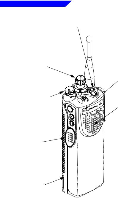
Switches, Buttons, Knobs, and Indicators
Bicolor LED
Indicates the radio’s operating status: Red =Transmitting
Blinking Red = Channel Busy or Low Battery (while transmitting)
Blinking Green = Receipt of Individual Call
16-Position Select Knob
Selects the operating system (zone) and/or specific channel.

 Antenna
Radiates and receives radio-frequency energy.
Microphone
Accepts audio.
On/Off/Volume |
|
Control Knob |
B |
|
A |
|
C |
Turns the radio on and off and adjusts the volume level.
Push-To-Talk
(PTT) Switch
Puts the radio in the transmit (send) mode.
Battery |
PRS |
Rechargeable, 7.5Vdc |
|
power source. |
|
 3000 XTS
Speaker
Emits audio.
4
Introduction
Antenna Installation and Removal
Before installing the antenna, ensure that the match between your radio and antenna is correct. Your radio’s model number is on a label attached to the back of your radio. A typical model number might be H09UCC9PW5AN. The fourth position of the model number (in this example “U”) identifies the operating-frequency band of the radio. The following table lists all fourthposition alpha characters and corresponding frequency band.
Radio Operating-Frequency Table
FourthOperating FourthOperating FourthOperating Fourth Operating Position Frequency Position Frequency Position Frequency Position Frequency
K |
136- |
R |
403- |
S |
450- |
U |
806- |
|
178MHz |
|
470MHz |
|
512MHz |
|
870MHz |
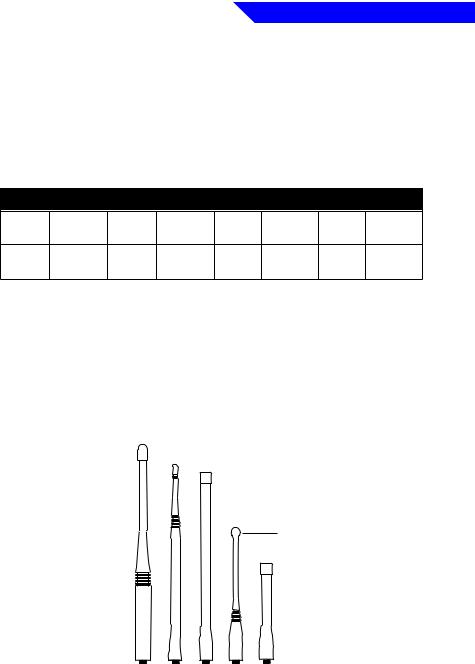
Antennas are frequency sensitive and are color coded according to the frequency range of the antenna. The color code indicator is in the center of the base of the antenna. The following illustrations and table will help identify the antenna, antenna frequency range, and corresponding color code.
|
DESCRIPTION |
|
|
|
ASTRO Antenna I |
||
|
ILLUSTRATOR |
DATE |
E |
|
EH |
12/8/92 |
|
VHF |
EDITOR |
DATE |
C |
PR |
12/9/92 |
|
|
Wide Band |
|
LETTERIN |
|
Helical |
|
REQUIRE |
|
|
|
|
|
800 MHz |
|
|
|
Dipole |
|
|
|
|
VHF |
|
|
|
Helical |
|
|
|
UHF |
|
|
|
800 MHz |
|
|
|
Whip |
|
|
|
800 MHz |
|
|
|
Stubby |
|
|
|
UHF |
|
|
|
Helical |
|
|
5

Introduction
Antenna Identification Table
Antenna Type |
Approx. Length |
Insulator |
Frequency |
Antenna |
||
|
|
|||||
in. |
mm |
Color Code |
Range |
Kit No. |
||
|
||||||
|
|
|
|
|||
|
|
|
|
|
|
|
VHF Wide Band |
8.1 |
203 |
RED |
136-174MHz |
NAD6563 |
|
Helical |
|
|
|
|
|
|
|
|
|
|
|
|
|
VHF Helical |
7.8 |
195 |
YELLOW |
136-151MHz |
NAD6566 |
|
|
7.3 |
183 |
BLACK |
151-162MHz |
NAD6567 |
|
|
6.9 |
172 |
BLUE |
162-174MHz |
NAD6568 |
|
|
|
|
|
|
|
|
UHF Helical |
3.3 |
83 |
RED |
403-435˙MHz |
NAE6546 |
|
|
3.2 |
80 |
GREEN |
435-470MHz |
NAE6547 |
|
|
3.2 |
79 |
BLACK |
470-512MHz |
NAE6548 |
|
|
|
|
|
|
|
|
UHF Wide Band Whip |
5.2 |
130 |
GREY |
403-512MHz |
NAE6549 |
|
|
|
|
|
|
|
|
800MHz Whip |
7 |
175 |
RED |
806-870MHz |
NAF5037 |
|
|
|
|
|
|
|
|
800MHz Dipole |
8 |
200 |
RED |
806-870MHz |
NAF5039 |
|
|
|
|
|
|
|
|
800MHz Stubby, |
3.3 |
83 |
WHITE |
806-870MHz |
NAF5042 |
|
Quarterwave |
|
|
|
|
|
|
|
|
|
|
|
|
|
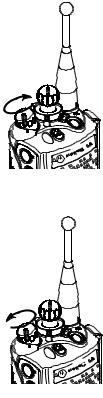
To install the antenna, screw the threaded end of the antenna into the antenna receptacle on the top of the radio. Rotate the antenna clockwise until it seats firmly against the bushing.
To remove the antenna, rotate the antenna counterclockwise until its threaded end unscrews from the radio’s antenna receptacle.
A
B
C

 3000
3000
XTS
6
Introduction
Battery Installation and Removal
! WARNING
To avoid a possible explosion:
DO NOT replace the battery in an area labeled “hazardous atmosphere.” DO NOT discard batteries in a fire.
! CAUTION
If your radio is programmed with volatile-key retention (consult your service technician), encryption keys will be retained for approximately 30 seconds after battery removal.
|
|
The battery is shipped uncharged, and must be charged before use. |
|
Note |
|
|
Refer to the “Battery Charging and Disposal” section on page 36. |
|
|
|
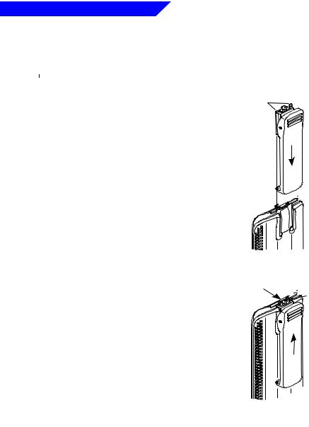
Installing the Battery
1. Turn off the radio and hold it with the back of the radio facing upward.
2. Insert the top edge of the battery into the area at the top of the radio between the radio’s case and chassis. Make sure the three tabs on the radio chassis align with the three slots under the top edge of the battery.
3.Rotate the battery toward the radio, and squeeze the battery and radio together until the battery “clicks” in place.
Removing the Battery
1. Turn off the radio and hold it so that the release button on the bottom of the battery is facing upward.
2. Press downward on the release button so that the battery disengages from the radio.
3. Remove the battery completely away from the radio
7
Introduction
Belt-Clip Installation and Removal
|
Note |
|
The battery must be removed from the radio before the belt clip |
|
|
||
|
|
can be installed or removed. |
|
|
|
|
|
|
|
|
Installing the Belt Clip
1.Hold the battery in one hand so that the top of the battery faces upward and the back of the battery faces you.
2.Holding the belt clip in the other hand with its top facing upward, align the slide assembly on the back of the belt clip with the slots on the back of the battery.
3.Slide the belt clip downward toward the bottom of the battery until the belt clip “clicks” in place.
Slide
Assembly
Belt Clip
Slots 


Battery
Removing the Belt Clip
1.Hold the battery (with belt clip installed) in one hand so that the top of the battery faces upward and the front (radio side) of the battery faces you.
2.At the top of the battery, press down on the belt clip’s metal tab and slide the belt clip upward until it disengages from the battery.
3.Continue to slide the belt clip upward until it is free from the battery.
Press
Down 

 Metal
Metal
Tab
8
Introduction
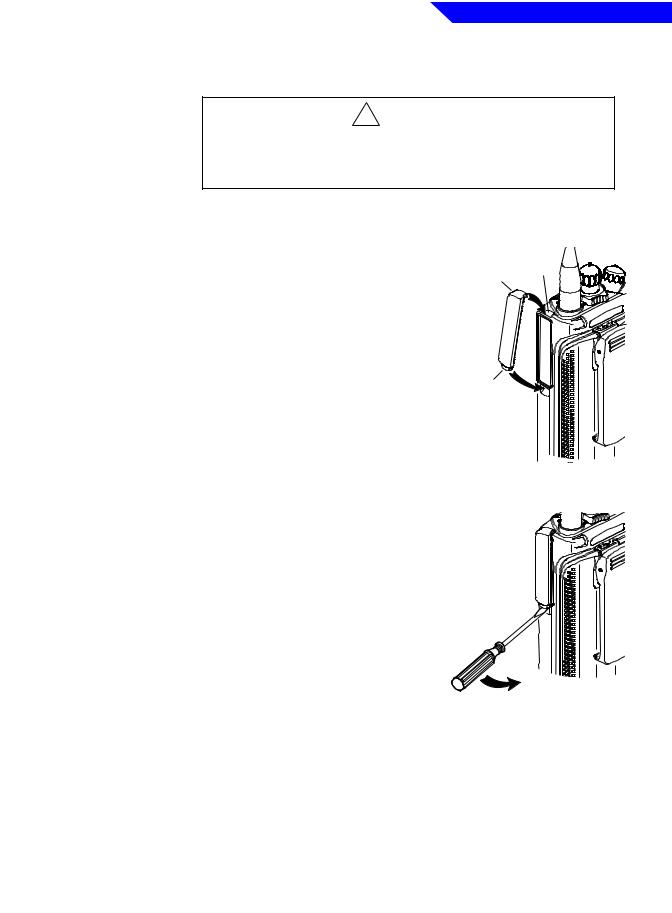
Universal Connector Cover
Installation and Removal
! CAUTION
When the universal connector is not in use, keep it covered with the universal connector cover.
Installing the Universal Connector Cover
1.Looking at the antenna side of the radio, insert the top (flat) hooked end of the cover into the slot on the top of the radio, above the universal connector. Press downward on the cover’s top to seat it in the slot.
2.While holding the cover seated in the top slot, insert the cover’s bottom (rounded) hooked end into the slot below the universal connector. Press firmly inward on the cover’s bottom until it snaps in place.
Top Top
Hooked End Slot
Bottom
Hooked End 

Bottom
Slot
Removing the Universal Connector Cover
1.Looking at the antenna side of the radio, insert a flat-bladed screwdriver into the area between the lower end of the universal connector cover and the slot below the universal connector.
2.Pry upward on the cover’s lower end until it disengages from the radio.
9

Introduction
Notes
10
2
General Radio Operations
After a fully-charged battery and an antenna have been connected to the radio, you can begin operation. If necessary, refer to page 2 to ensure a complete understanding of the radio’s controls and indicators. Also, for your convenience, the “Additional Information” section (starting on page 33) contains a glossary, alert tone table, helpful tips, and an index.
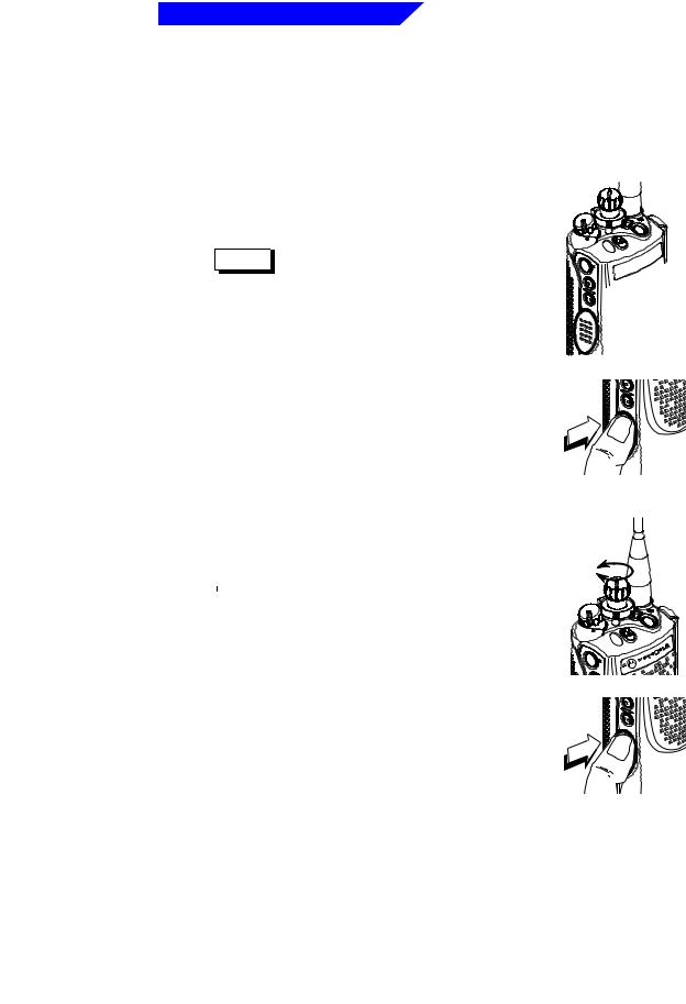
Turning the Radio On and Off
On
A
B
C

 3000 XTS
Radio On
Turn the radio on by rotating the On/Off/Volume Control Knob clockwise.
The radio then goes through a power-up self test. When the radio passes the self test, a mediumpitched tone sounds. This tone is programmable through radio service software.
If the radio fails the self test, a low-pitched tone will sound. Turn the radio off, check the battery, and turn the radio back on. If the radio still does not pass its self test, contact your nearest authorized service technician.
Radio Off
Turn the radio off by rotating the On/Off/Volume
Control Knob counterclockwise until you hear a click.
Off
A
B
C

 3000
3000
XTS
11
General Radio Operations
Selecting a Zone and Channel
A zone is a grouping of channels. A channel is a group of radio characteristics such as transmit/receive frequency pairs. After you turn your radio on, select the desired zone and channel.
Zone Selection
1.Place the Zone Switch (if programmed, see page 2) to the desired position.
Notes 

•If the selected zone is unprogrammed, you will hear a continuous, low-pitched tone (invalid-mode tone) until a valid programmed zone is selected. This does not mean your radio is unprogrammed, only that the zone you selected is unprogrammed.
•If you would like a different channel within the selected zone, see “Channel Selection” on this page.
2.To transmit on the selected zone/channel combination, press the PTT Switch.
A
B
C
2 |
|
page |
|
See |
|
your |
|
for |
|
radio’s- |
. |
feature |
|
programming |
|
control |
|
Channel Selection
1. Once you have a desired zone, rotate the 16- |
|
Position Select Knob to the desired channel. |
Select |
|
Channel |
|
Note |
If the selected channel is unprogrammed, |
|
|
you will hear a continuous, low-pitched |
|
|
|
|
|
tone (invalid-mode tone) until a valid |
|
|
programmed channel is selected. This does |
|
|
not mean your radio is unprogrammed, |
|
|
only that the channel you selected is |
|
|
unprogrammed. |
A |
B |
C |
3000 |
XTS |
2.To transmit on the selected zone/channel combination, press the PTT Switch.
12
Loading...