


WS-65313
Mitsubishi WS-65313, WS-65413, WS-55313, WS-55413, WS-48413 Service Manual
...
MITSUBISHI DIGITAL ELECTRONICS AMERICA, INC.
9351 Jeronimo Road, Irvine, CA 92618-1904
Copyright © 2003 Mitsubishi Digital Electronics America, Inc.
All Rights Reserved
CAUTION:
Before servicing this chassis, it is important that the service person read the "SAFETY PRECAUTIONS" and
"PRODUCT SAFETY NOTICE" contained in this manual.
MITSUBISHI ELECTRIC
Service
Manual
2003
Weight and dimensions shown are approximate.
Design specifications are subject to change without notice.
PROJECTION TELEVISION
V22 / V22+ CHASSIS
SPECIFICATIONS
Power : AC 120V, 60Hz
240W
Frequency : VHF 54 ~ 470MHz
Range UHF 470 ~ 806MHz
Antenna Input : VHF/UHF 75Ω unbalanced
CRT Size : 7 inches
High Voltage : 30.8KV
• Speakers : [WS-48313 / WS-48413]
Two 5" round, full range (8Ω 10W)
: [WS-55313 / WS-55413 / WS-65313/
WS-65413]
Two 6" round, full range (8Ω 10W)
Weight / Cabinet Demensions
• Input Level : VIDEO IN JACK (RCA Type)
1.0Vp-p 75Ω unbalanced
: AUDIO IN JACK (RCA T ype)
-4.7dBm 43kΩ unbalanced
: S-VIDEO IN JACK (Y/C separate)
Y=1.0 Vp-p C=0.286Vp-p(BURST)
75Ω unbalanced
: COMP / Y, Cr , Cb (RCA T ype)
Y=1.0 Vp-p. Cr , Cb=700mVp-p
: DTV / Y(G), Pr(R), Pb(B), H, V
Y 1.0Vp-p with sync 75Ω (RCA Type)
Pr, Pb: 700mV 75Ω
H, V: 3.0Vp-p 75Ω
• Digital Inputs
:MonitorLink
TM
/DVI
:MonitorLink
TM
Control/RS-232C
• Output Level : VIDEO OUT JACK (RCA T ype)
1.0Vp-p 75Ω unbalanced
: AUDIO OUT JACK (RCA
Type)
-4.7dBm 4.7kΩ unbalanced
V22 Chassis
MODELS
WS-48313
WS-55313
WS-65313
V22+ Chassis
MODELS
WS-48413
WS-55413
WS-65413
WS-48313
Model Weight Height Width Depth
WS-48313
172 lbs 49" 44.5" 24"
WS-48413 172lbs 49" 44.5" 24"
WS-55313 213 lbs 50.4" 50.5" 25.4"
WS-55413 221 lbs 50.4" 50.5" 27.8"
WS-65313
327 lbs 62" 59" 28"
WS-65413 327 lbs 62" 59" 28"


MODELS: WS-48313 / WS-48413 / WS-55313 / WS-55413 / WS-65313 / WS-65413
Page 3
INTRODUCTION ............................................................................................................................... 5
PRODUCT SAFETY NOTICE ...........................................................................................................5
SAFETY PRECAUTIONS ................................................................................................................. 6
DISASSEMBLY PROCEDURES ......................................................................................................... 7
WS-48313 / WS-48413
Front Cabinet Components .................................................................................................... 7
Rear Cabinet Components ..................................................................................................... 8
WS-55313 / WS-55413 / WS-65313 / WS-65413
Front Cabinet Components .................................................................................................... 9
Rear Cabinet Components ................................................................................................... 10
SERVICING THE LENTICULAR LENS AND FRESNEL SCREEN ................................................ 11
WS-48313 / WS-48413
Removal of the Lenticular Screen and Fresnel Lens .......................................................... 11
WS-55313 / WS-55413 / WS-65313 / WS-65413
Removal of the Lenticular Screen and Fresnel Lens .......................................................... 12
All Models
Installation of the Lenticular Screen and Fresnel Lens ....................................................... 13
CABINET SEPARATION PROCEDURES .......................................................................................... 14
WS-65313 / WS-65413 ................................................................................................................. 14
SERVICING THE DIAMONDSHIELDS
TM
r ........................................................................................ 15
DiamondShields
TM
Removal ......................................................................................................... 15
DiamondShields
TM
Installation ...................................................................................................... 15
SERVICING PCBs ............................................................................................................................ 16
Chassis Removal .......................................................................................................................... 16
PCB Locations .............................................................................................................................. 16
Major Parts Locations ................................................................................................................... 16
ANODE LEAD REMOVAL ................................................................................................................. 17
CRT REPLACEMENT ....................................................................................................................... 17
CRT Removal ................................................................................................................................17
CRT Installation ............................................................................................................................ 18
ELECTRICAL ADJUSTMENTS ...................................................................................................... 20
Equipment .................................................................................................................................... 20
Initial Setup ................................................................................................................................... 21
LED Indicator Diagnostics ............................................................................................................. 22
Circuit Adjustment Mode ............................................................................................................... 23
Convergence Adjustment Mode ..................................................................................................... 24
Adjustment Items List ................................................................................................................... 26
Adjustment Procedures ................................................................................................................ 29
Test Point Locations ............................................................................................................29
HV Regulation ...................................................................................................................... 30
Main / Sub Y Level ............................................................................................................... 30
Main / Sub Color Level ......................................................................................................... 31
CRT Cutoff ........................................................................................................................... 31
White Balance (NTSC) ......................................................................................................... 32
CONTENTS

MODELS: WS-48313 / WS-48413 / WS-55313 / WS-55413 / WS-65313 / WS-65413
Page 4
White Balance (HD) ............................................................................................................. 32
Black Level .......................................................................................................................... 33
Sub Contrast ....................................................................................................................... 33
Dynamic Focus Presets ...................................................................................................... 34
Lens Focus.......................................................................................................................... 34
Alignment Magnet & Electrostatic Focus ............................................................................. 35
Charactrer Position .............................................................................................................. 35
Geometry Presets ............................................................................................................... 36
Deflection Geometry Adjustments ........................................................................................ 37
Convergence Geometry Adjustments ................................................................................... 38
Centering & Static Convergence ........................................................................................... 39
Coarse Convergence Adjustments ........................................................................................ 40
Fine Convergence Adjustments ............................................................................................ 41
CHIP PARTS REPLACEMENT ......................................................................................................... 42
REPLACEMENT PARTS .................................................................................................................. 43
Parts Ordering .............................................................................................................................. 43
Critical and Warranty Parts Designation........................................................................................ 43
Parts Tolerance Codes .................................................................................................................. 43
Quick Reference List .................................................................................................................... 44
SERVICE PARTS LIST .................................................................................................................... 45
SCREEN ASSEMBLY PARTS LIST.................................................................................................. 57
CIRCUITRY BLOCK DIAGRAMS ..................................................................................................... 60
Part 2
Schematic Diagrams
CONTENTS Page
SCHEMATIC DIAGRAMS
PCB Interconnect Diagram.............................................................................................................. 1
PCB-MAIN ...................................................................................................................................... 2
PCB-POWER ................................................................................................................................. 3
PCB-SIGNAL-1 (TUNER I/O) ........................................................................................................... 4
PCB-SIGNAL-2 (MICRO) ................................................................................................................. 5
PCB-SIGNAL-3 (VIDEO / CHROMA) ............................................................................................... 6
PCB-SIGNAL-4 (CONVERGENCE GENERATOR) .......................................................................... 7
PCB-DOUBLER-1 ........................................................................................................................... 8
PCB-DOUBLER-2 ........................................................................................................................... 9
PCB-DOUBLER-3 ......................................................................................................................... 10
PCB-TERMINAL-1 (A/V I/O) .......................................................................................................... 11
PCB-TERMINAL-2 (MonLink) ........................................................................................................ 12
PCBsCRT, CONTROL, FRONT and PREAMP .............................................................................. 13
PCB LAYOUT DIAGRAMS ............................................................................................................... 14
MODELS: WS-48313 / WS-48413 / WS-55313 / WS-55413 / WS-65313 / WS-65413
Page 5
INTRODUCTION
This service manual provides service instructions for the PTV Models listed below. Service personnel should read this
manual thoroughly before servicing these chassis.
This service manual includes:
1. Assembly and disassembly instructions for the front and rear cabinet components.
2. Servicing of the Lenticular Screen and Fresnel Lens.
3. Servicing printed circuit boards (PCBs).
4. CRT replacement procedure.
5. Electrical adjustments.
6. Chip parts replacement procedures.
7. Circuit path diagrams.
The parts list section of this service manual includes:
1. Cabinet and screen parts.
2. Electrical parts.
Schematic and block diagrams of the above listed models are included in this service manual for better under-
standing of the circuitry. PCB drawings are also included for easy location of parts and test points.
PRODUCT SAFETY NOTICE
Many electrical and mechanical parts in television receivers have special safety related characteristics. These
characteristics are often not evident from visual inspection nor can the protection afforded by them necessarily be
obtained by using replacement components rated for higher voltage, wattage, etc.
Replacement parts which have special safety characteristics are identified in this service manual.
Electrical components having such features are identified by shading on the schematic diagram and by bold
type in the parts list of this service manual. The replacement for any safety part should be identical in value
and characteristics.
V22 Chassis V22+ Chassis
WS-48313 WS-48413
WS-55313 WS-55413
WS-65313 WS-65413

MODELS: WS-48313 / WS-48413 / WS-55313 / WS-55413 / WS-65313 / WS-65413
Page 6
SAFETY PRECAUTIONS
NOTICE: Observe all cautions and safety related notes located inside the receiver cabinet and on the
receiver chassis.
WARNING:
1. Operation of this receiver outside the cabinet or with the cover removed presents a shock hazard
from the receiver's power supplies. Work on the receiver should not be attempted by anyone who is
not thoroughly familiar with the precautions necessary when working on high voltage equipment.
2. Do not install, remove or handle the picture tubes in any manner unless shatterproof goggles are
worn. People not so equipped should be kept away while the picture tube is being handled. Keep
the picture tube away from the body while handling.
3. When service is required, observe the original lead dress. Extra precaution should be taken to
assure correct lead dress in the high voltage area. Where a short-circuit has occurred, replace those
components that indicate evidence of overheating.
X-Radiation warning
The surface of the cathode ray tubes (CRTs) may generate X-Radiation, so take proper precautions when servic-
ing. It is recommended that a lead apron be used for shielding while handling the CRT. Use this method if
possible.
When replacing the CRTs, use only the designated replacement part since it is a critical component with regard to
X-Radiation. High voltage must be set as prescribed under the section titled Electrical Adjustments.
Leakage current check
Before returning the receiver to the customer, it is recommended that leakage current be measured according to
the following methods.
1. Cold Check
With the alternating current (AC) plug removed from the AC source, place a jumper across the two AC plug
prongs. Connect one lead of an ohm meter to the AC plug and touch the other lead to each exposed metal
part (i.e. antennas, handle bracket, metal cabinet, screw heads, metal overlay, control shafts, etc.), particu-
larly any exposed metal part that has a return path to the chassis. The resistance of the exposed metal parts
having a return path to the chassis should be a minimum of 1Mega Ohm. Any resistance below this value
indicates an abnormal condition and requires corrective action.
2. Hot Check ...Use the circuit shown below to perform the hot check test.
1. Keep switch S1 open and connect the receiver to the measuring circuit. Immediately after
connection, and with the switching devices of the receiver in their operating positions, measure
the leakage current for both positions of switch S2.
2. Close switch S1, energizing the receiver. Immediately after closing switch S1, and with the
switching devices of the receiver in their operating positions, measure the leakage current for both
positions of switch S2. Repeat the current measurements of items 1 and 2 after the receiver has
reached thermal stabilization. The leakage current must not exceed 0.5 milliampere (mA).
MODELS: WS-48313 / WS-48413 / WS-55313 / WS-55413 / WS-65313 / WS-65413
Page 7
*Refer to PARTS LIST for Part Numbers
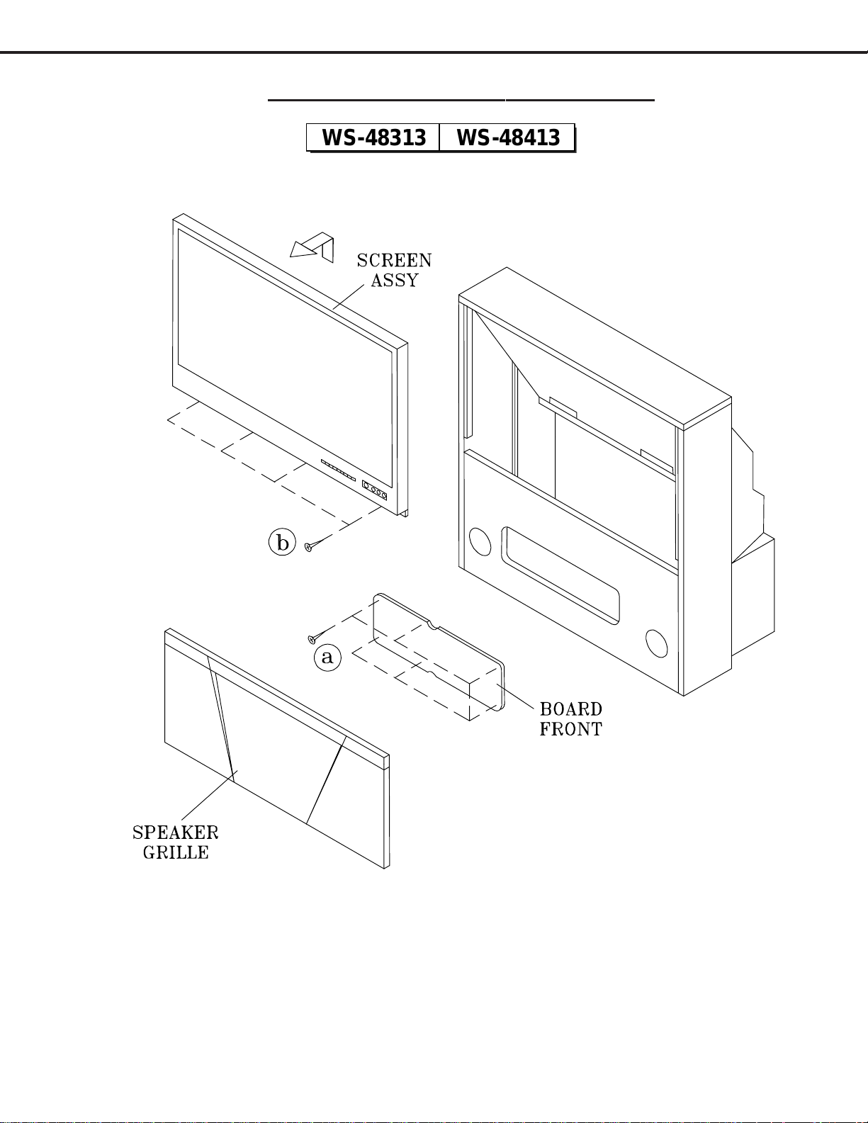
CABINET DISASSEMBLY (FRONT VIEW)
Front Cabinet Disassembly
1. Remove the Speaker Grille by pulling forward.
2. Remove the Board-Front by removing six screws "a".
3. Remove the Screen Assembly by removing four screws "b". Disconnect all cable harnesses between the
Screen Assembly and the PCB-Signal.
4. Lift the Screen Assembly and pull up and away from the cabinet as shown.
WS-48313 WS-48413
MODELS: WS-48313 / WS-48413 / WS-55313 / WS-55413 / WS-65313 / WS-65413
Page 8
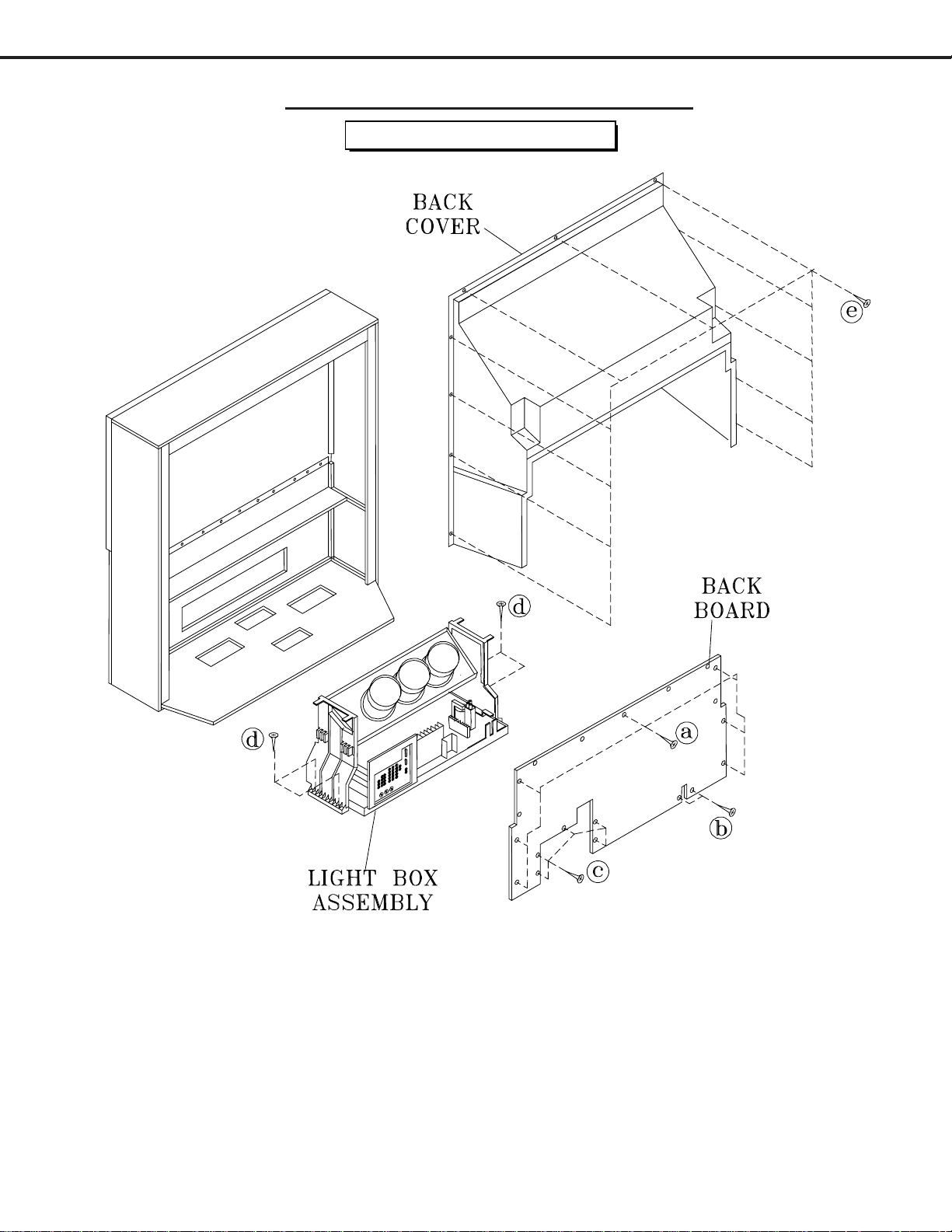
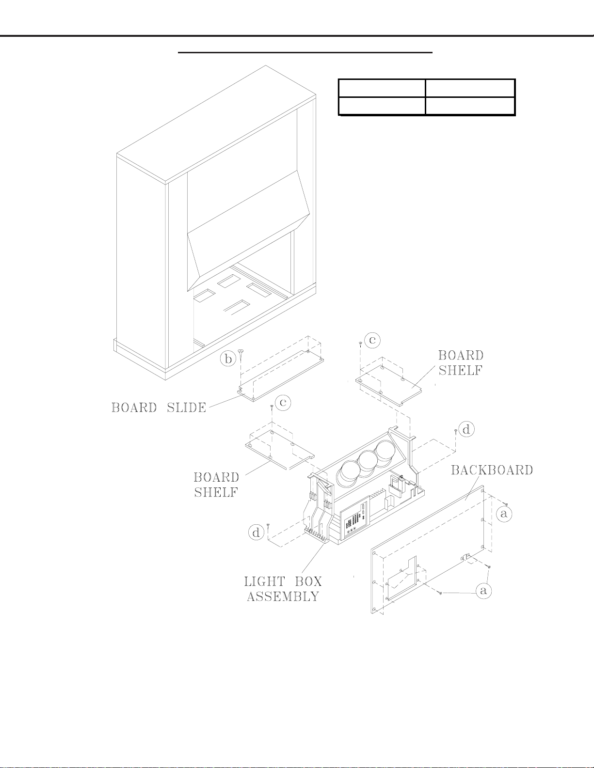
CABINET DISASSEMBLY (REAR VIEW)
Rear Cabinet Disassembly
1. Remove the Back Board by removing 14 screws "a", b and c.
2. Remove the Back Cover by removing screws "e".
3. Remove 4 screws "d" securing the Light Box Assembly.
4. Be certain that all cables and connectors between the Light Box Assembly and external items are discon-
nected (e.g. speaker plugs).
5. Slide the Light Box Assembly out of the cabinet.
WS-48313 / WS-48413
MODELS: WS-48313 / WS-48413 / WS-55313 / WS-55413 / WS-65313 / WS-65413
Page 9
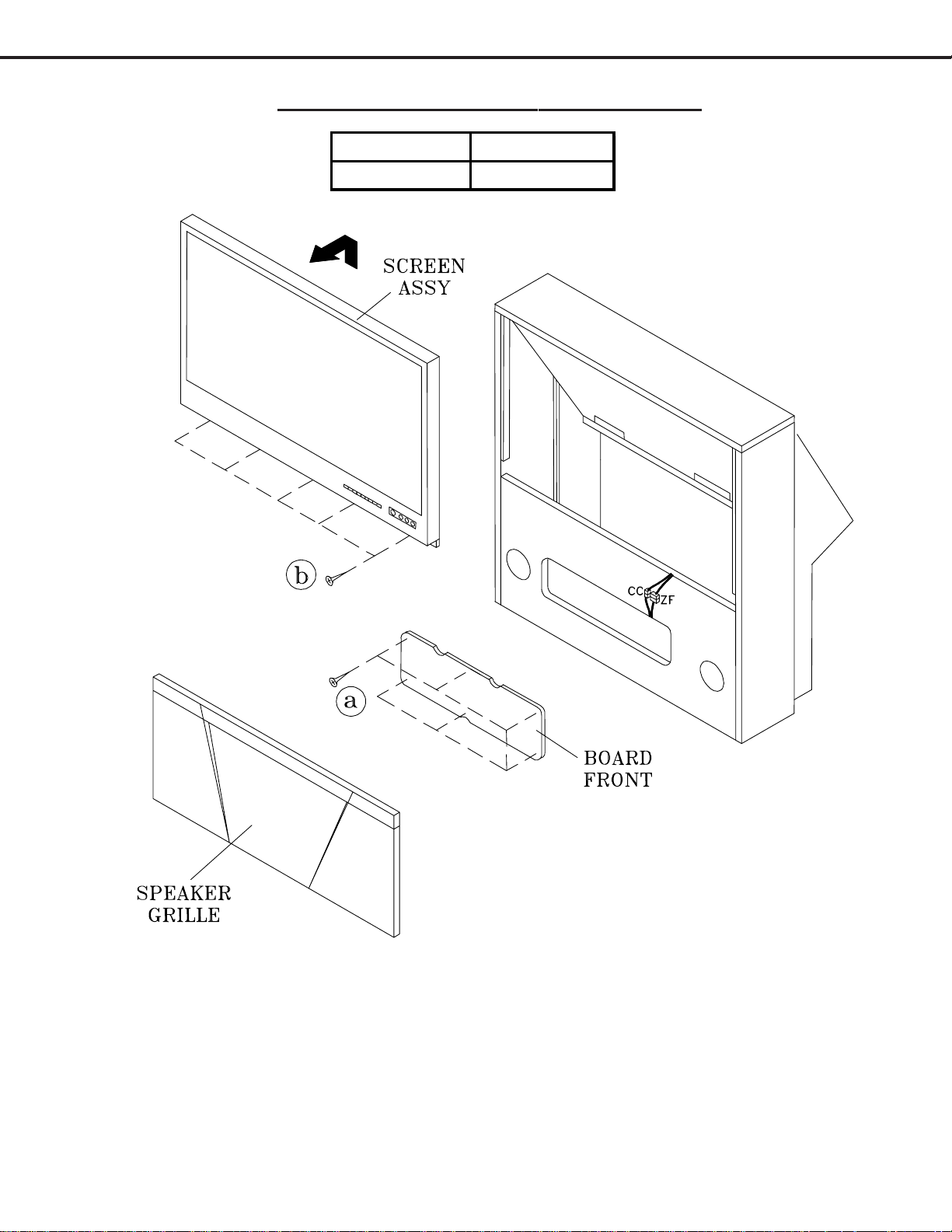
CABINET DISASSEMBLY (FRONT VIEW)
Front Cabinet Disassembly
1. Remove the Speaker Grille by pulling forward.
2. Remove the Front-Board by removing screws "a".
3. Remove the Screen Assembly by removing 5 screws "b". Disconnect connectors CC and ZF between the
Screen Assembly and the PCB-Signal.
4. Lift the Screen Assembly and pull up and away from the cabinet as shown.
WS-55313 WS-55413
WS-65313 WS-65413
MODELS: WS-48313 / WS-48413 / WS-55313 / WS-55413 / WS-65313 / WS-65413
Page 10
CABINET DISASSEMBLY (REAR VIEW)
Rear Cabinet Disassembly
1. Remove the Back Board by removing 13 screws "a" (15 screws a in 65 inch models).
2. Remove the Board Slide by removing four screws b.
3. Remove the two Board Shelves by removing 8 screws c.
4. Remove 4 screws "d" securing the Light Box Assembly.
5. Be certain that all cables and connectors between the Light Box Assembly and external items are discon-
nected (connectors CC, ZF and EJ)).
6. Slide the Light Box Assembly out of the cabinet.
WS-55313 WS-55413
WS-65313 WS-65413
MODELS: WS-48313 / WS-48413 / WS-55313 / WS-55413 / WS-65313 / WS-65413
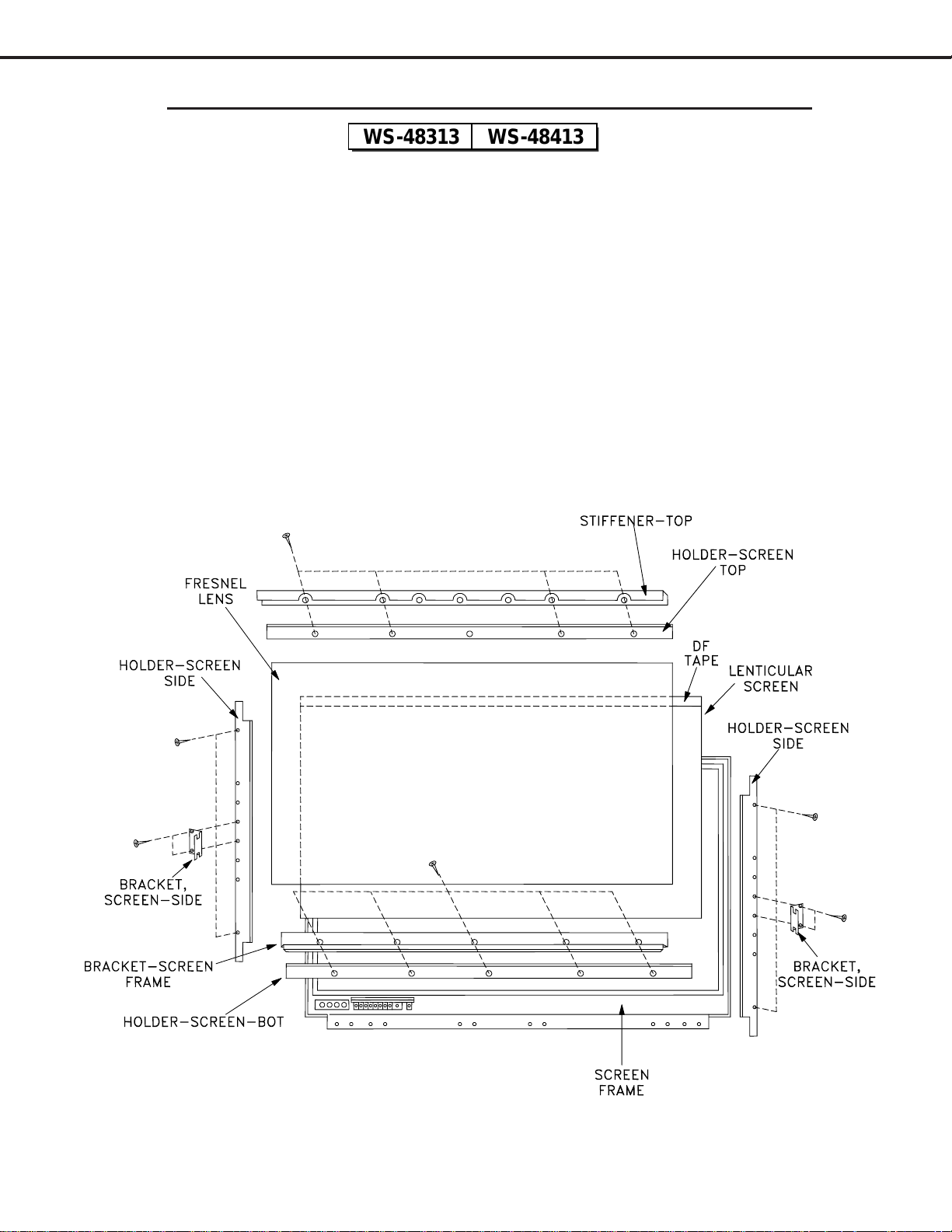
Page 11
SERVICING THE LENTICULAR SCREEN AND FRESNEL LENS
CAUTION: Wear gloves when handling the Lenticular Screen and Fresnel Lens.
This prevents cuts and finger prints. Do not place Fresnel Lens in the sun.
This may cause fire and heat related injuries.
1a. Lenticular Screen and Fresnel Lens Removal
1. Remove the screen assembly as shown in the Cabinet Disassembly procedure.
2. Remove the Top, Bottom and Side Holder Screens..
3. Carefully lift the Lenticular Screen and Fresnel Lens combination from the Screen Frame Assembly.
Note: When separating the Lenticular Screen from the Fresnel Lens, use caution
while prying the Screen and Lens apart. Use a slot type screw driver, and
remove the pressure sensitive double sided tape.
WS-48313 WS-48413
MODELS: WS-48313 / WS-48413 / WS-55313 / WS-55413 / WS-65313 / WS-65413
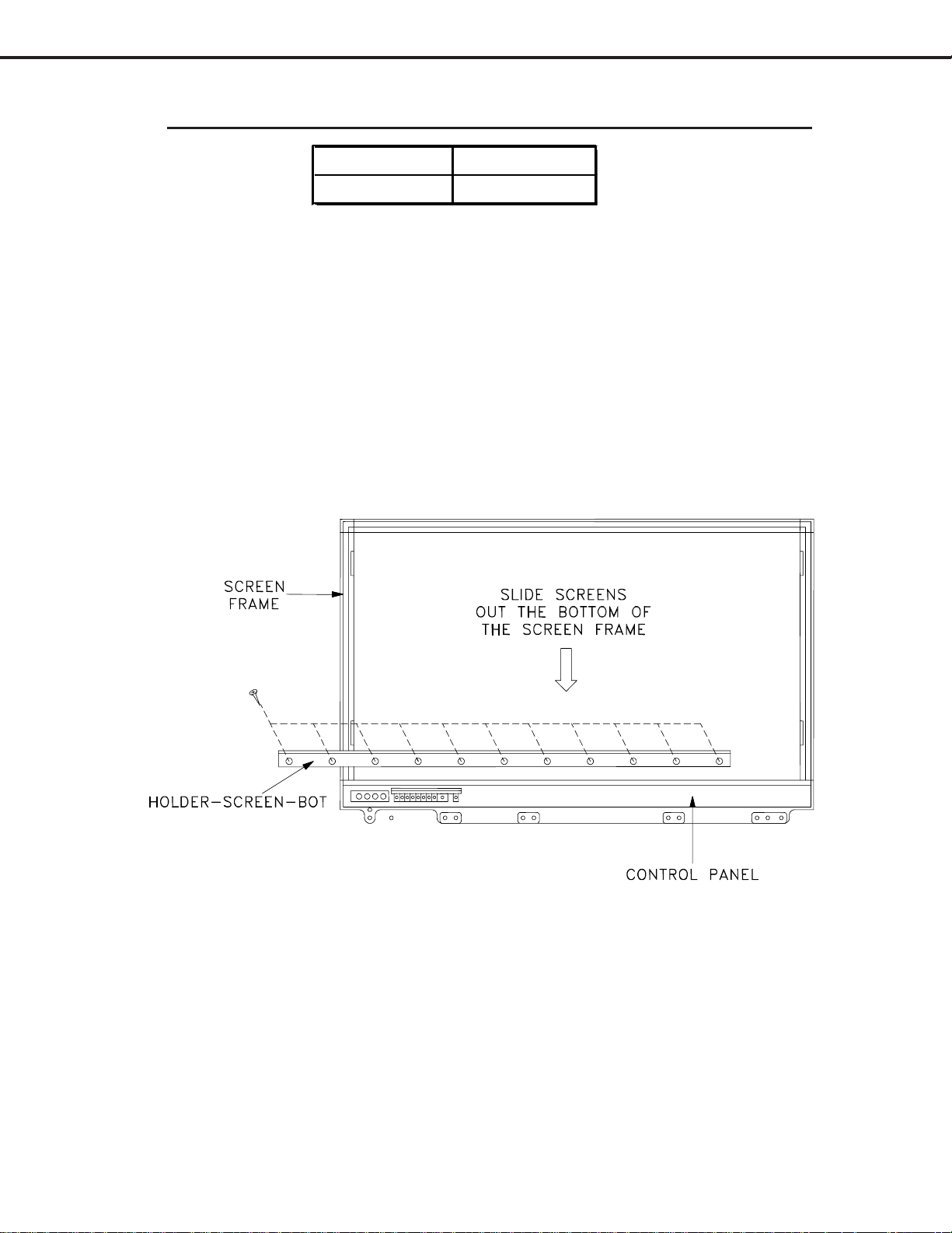
Page 12
SERVICING THE LENTICULAR SCREEN AND FRESNEL LENS
CAUTION: Wear gloves when handling the Lenticular Screen and Fresnel Lens.
This prevents cuts and finger prints. Do not place Fresnel Lens in the sun.
This may cause fire and heat related injuries.
1b. Lenticular Screen and Fresnel Lens Removal
1. Remove the screen assembly as shown in the Cabinet Disassembly procedure.
2. Remove the HOLDER-SCREEN-BOTTOM.
3. Carefully slide the Lenticular Screen and Fresnel Lens combination from the upper Screen Frame Assembly.
Note: When separating the Lenticular Screen from the Fresnel Lens, use caution
while prying the Screen and Lens apart. Use a slot type screw driver, and
remove the pressure sensitive double sided tape.
WS-55313 WS-55413
WS-65313 WS-65413
1b. Installing the Fresnel Lens and Lenticular Screen
1. Insert the Lenticular Screen and Fresnel Lens combination into the upper Screen Frame.
2. Install the HOLDER-SCREEN-BOTTOM, install the end screws first. .
MODELS: WS-48313 / WS-48413 / WS-55313 / WS-55413 / WS-65313 / WS-65413
Page 13
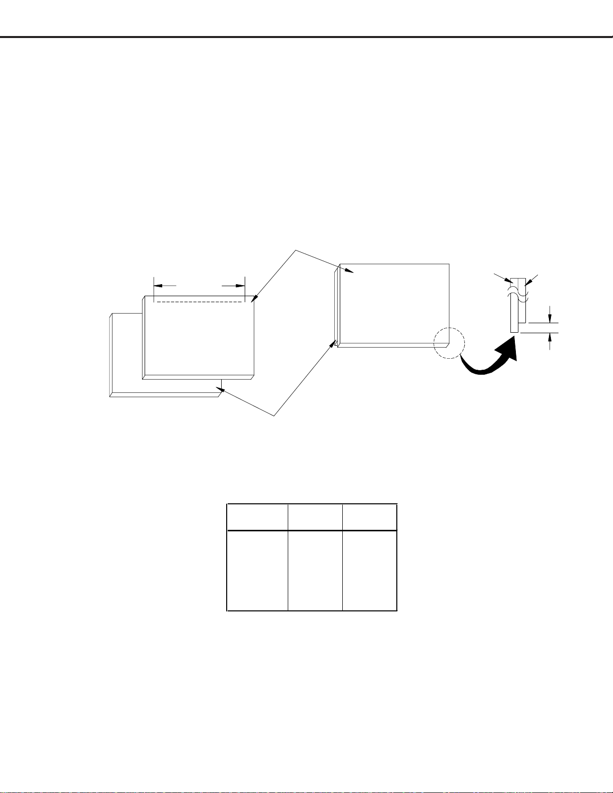
2. Installation of the Lenticular Screen and Fresnel Lens
Note: Store the Lenticular Screen and Fresnel Lens in a cool dry place. High humidity may
deform the Lenticular Screen and Fresnel Lens.
1. Apply double coated tape (Part # LENS-TAPE) along the top front edge of the Fresnel Lens
as shown in Figure 2-2. Refer to Table B for proper tape length.
2. Place the Fresnel Lens on top of the Lenticular Screen and apply pressure at the top edge to
bond them together as shown in Figure 2-2.
3. Reverse the disassembly procedure for that model to install the screens in the screen frame.
Lenticular Screen
Fresnel Lens
0.16 inch
Figure 2-2
Lenticular
Screen
Fresnel
Lens
To p
Bottom
Double Sided Tape
(Part# LENS-TAPE)
( * X ) inch
To p
Bottom
Model
Screen
Size
Tape
Length
WS-48313 48" 41.76
WS-48413 48" 41.76
WS-55313 55" 47.85
WS-55413 55" 47.85
WS-65313 65" 56.55
WS-65413 65" 56.55
Table A
MODELS: WS-48313 / WS-48413 / WS-55313 / WS-55413 / WS-65313 / WS-65413
Page 14
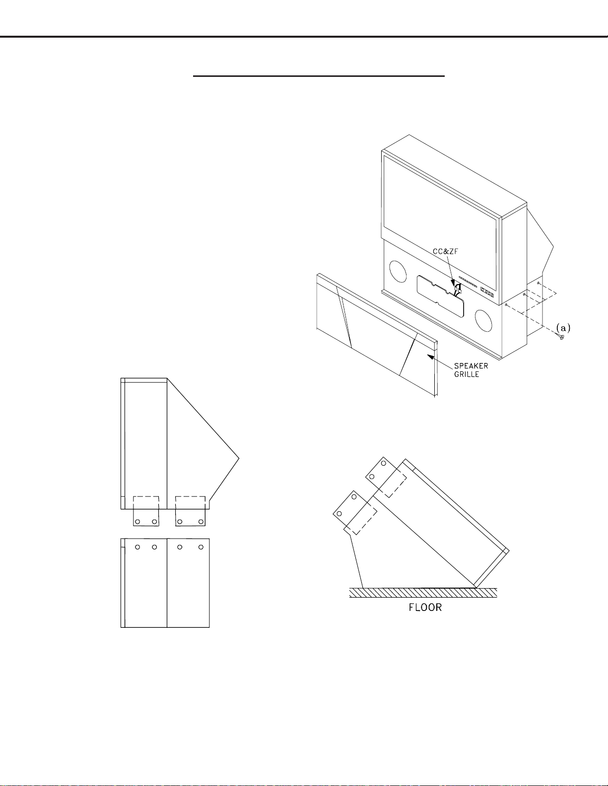
CABINET SEPARATION PROCEDURE
(WS-65313 / WS-65413)
Cabinet Separation Precedure
(Figure 1)
1. Pull the Speaker Grille off.
2. Unplug connectors CC and ZF.
3. Remove 4 screws a on both sides of the
cabinet.
(Figure 2)
4. Carefully lift the cabinet top until the support
tabs clear the bottom cabinet.
(Figure 3)
5. Carefully rotate the cabinet top and place it on
the floor.
6. Reverse the procedure and mount the cabinet
top on the cabinet bottom.
Models WS-65313, and WS-65413 cabinets are assembled in two pieces. These two pieces may be separated to
allow easier delivery and setup.
Figure 1
Figure 2
Figure 3
MODELS: WS-48313 / WS-48413 / WS-55313 / WS-55413 / WS-65313 / WS-65413
Page 15
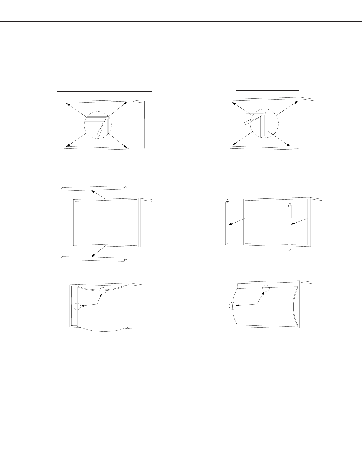
SERVICING THE DIAMONDSHIELD
1. DiamondShield Removal Procedure
The location of the DiamondShield
TM
molding clips may vary between models, top and bottom, or sides. Use
the appropriate disassembly procedure given below.
Note: Wear gloves when handling the DiamondShield to prevent finger prints.
1. Gently insert a small screwdriver between the
DiamondShield and one end of the clip to pry
the clip loose.
2. Remove both clips by pulling them toward you.
3. Carefully insert a small screwdriver into the gap
at the top/center point of the Shield and pull the
Shield slightly away from the unit. Place your
hands at the points shown and gently bow the
Shield toward you and remove from the unit.
Then re-install the two clips.
Top & Bottom Molding Clips
Side Molding Clips
1. Gently insert a small screwdriver between the
DiamondShield and one end of the clip to pry
the clip loose.
2. Remove both clips by pulling them toward you.
3. Carefully insert a small screwdriver into the gap
at the side/center point of the Shield and pull the
Shield slightly away from the unit. Place your
hands at the points shown and gently bow the
Shield toward you and remove from the unit.
Then re-install the two clips.
2. DiamondShield Installation Procedure
*(See the Parts List for DiamondShield part numbers)
To install the DiamondShieldTM, reverse the above Removal Procedure.

MODELS: WS-48313 / WS-48413 / WS-55313 / WS-55413 / WS-65313 / WS-65413
Page 16
SERVICING PCBs
Chassis Removal and PCB Locations
Major Parts Locations
Chassis Removal
1) Remove screw a from the Main Chassis.
2) Raise the two chassis locks on the inner sides of the
Lightbox Assembly and slide the chassis towards the
rear.

MODELS: WS-48313 / WS-48413 / WS-55313 / WS-55413 / WS-65313 / WS-65413
Page 17
ANODE LEAD REMOVAL
CAUTION: To prevent damage, the following procedure must be used when removing an
Anode Lead from the Flyback Transformer.
1) Push the Anode Lead down.
CRT REPLACEMENT
1. Removal of the CRT
Caution! High voltage should be completely discharged prior to CRT removal.
Since the CRTs receive high voltage from the Flyback transformer, discharge
by shorting the open end of the respective high voltage cable to chassis ground.
Note: Refer to Cabinet Disassembly when performing steps 1 through 2.
1. Remove the Speaker Grille, Front Board, and Screen Assy.
2. Remove the Back Board.
3. Remove the Anode Lead Wire from the Flyback transformer. (Use the above procedure)
4. Remove the PCB-CRT.
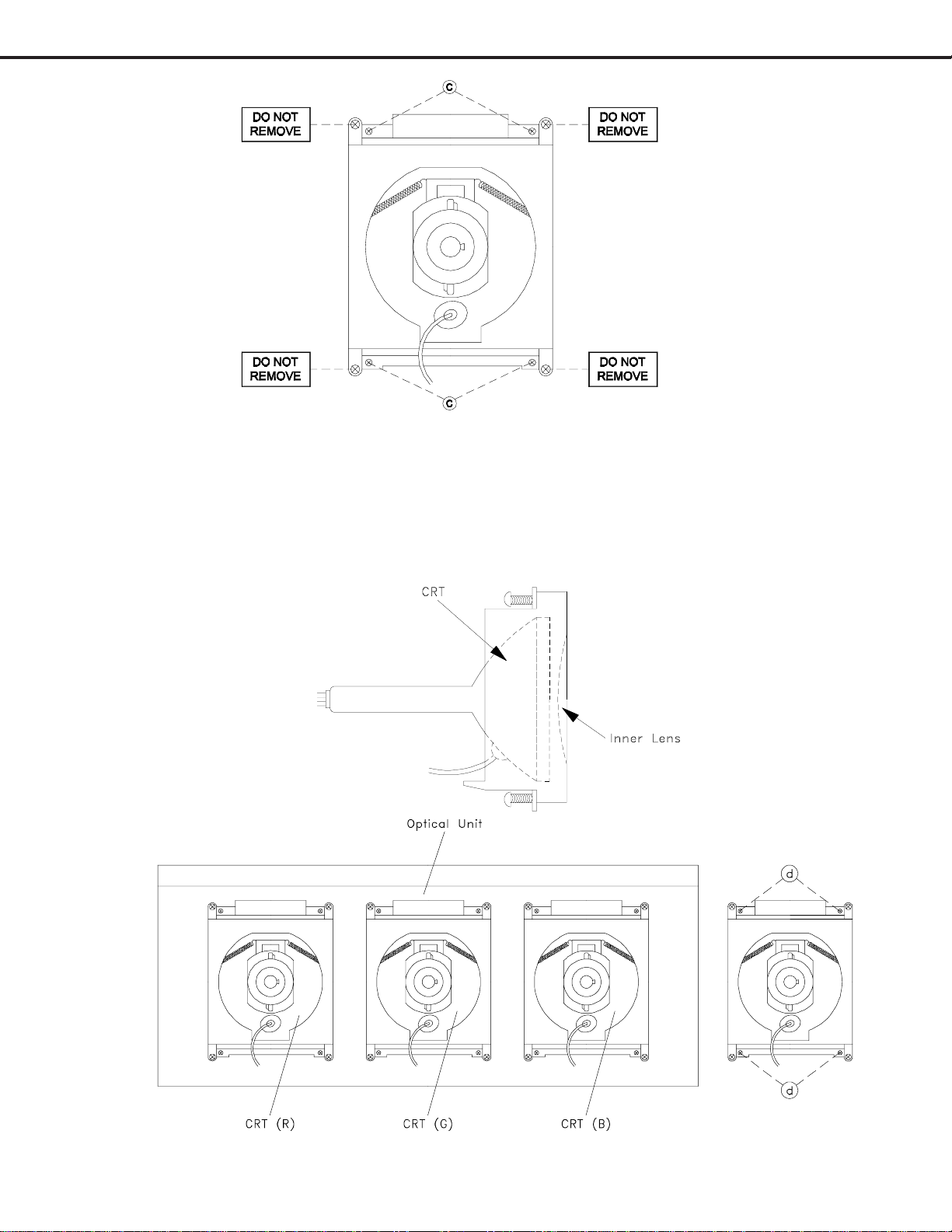
5. Remove 4 hex-screws "a" retaining the Optical Unit. [Figure 5-1]
6. Remove 4 screws "b" retaining the Lens.
Note: DO NOT loosen the RED screws. Doing so will break the seal between the
C-Element and the # 6 Lens, causing leakage of the CRT Coolant.
7. Remove 4 screws "c" retaining the CRT. [Figure 5-2]
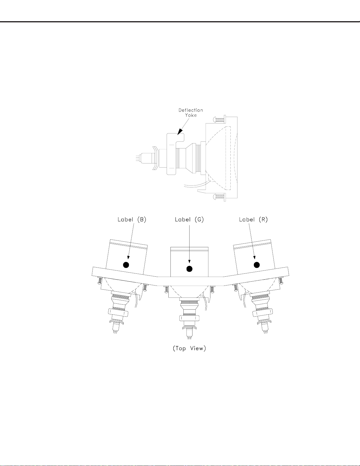
8. Remove the Deflection Yoke and other CRT components from the neck of the CRT. [Figure 5-6]
2) While holding the lead down rotate
the lead 90º counter clockwise.
3) Carefully remove the Anode Lead
from the Flyback Transformer.
Figure 5-1
MODELS: WS-48313 / WS-48413 / WS-55313 / WS-55413 / WS-65313 / WS-65413
Page 18
Figure 5-2
Note: The 4 spring-loaded screws shown
in Fig 5-2 and labeled as "DO NOT
REMOVE", should not be loosened
under any circumstance. Doing so
will break the seal between the
CRT and the CRT-Spacer, causing
leakage of the CRT Coolant.
2. Installation of the CRT
Note: The replacement CRT is supplied as an assembly comprised of the CRT and the
Inner Lens with the space between them filled with ethylene glycol. Care should
be taken during handling and installation to prevent shock from disrupting the seal
or alignment between the CRT and Inner Lens. [Figure 5-3]
Figure 5-3
Figure 5-5
Figure 5-4
MODELS: WS-48313 / WS-48413 / WS-55313 / WS-55413 / WS-65313 / WS-65413
Page 19
1. Carefully position the replacement CRT and fasten in place using 4 screws "d". [Figure 5-5]
2. Install the Deflection Yoke and other CRT components back in there original position on the CRT neck.
[Figure 5-6]
3. Install the Lens that was removed in step6 of Removal Of The CRT. [ Figures 5-1 and 5-2 ]
a) Position the Lens so that the Label faces the direction shown in Figure 5-7
b) Install the mounting screws b. [Figure 5-1]
4. Insert the Optical Unit into the Light Box Assembly.
5. Install the PCB-CRT.
6. Insert the Anode Lead Wire into the Flyback Transformer.
7. Re-clamp the Lead Wire in its original position.
Figure 5-6
Figure 5-7
Adjustment procedures after replacing the CRT(s)
CRT Cut Off / White Balance Adjustment
Static Convergence Adjustment
Dynamic Convergence Adjustment
Page 20
MODELS: WS-48313 / WS-48413 / WS-55313 / WS-55413 / WS-65313 / WS-65413
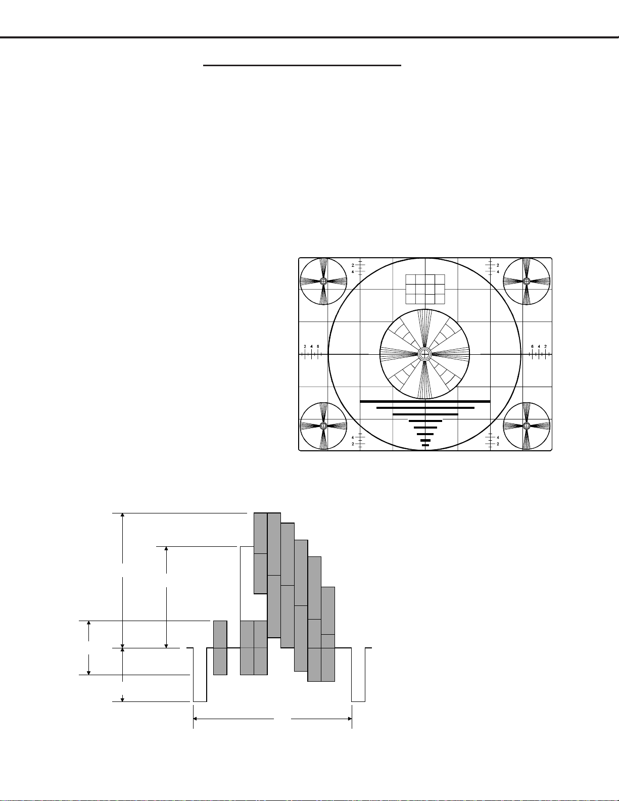
1H
40%
40%
100%
75%
Monoscope Signal
Split-Field Color Bars (100% window)
ELECTRICAL ADJUSTMENTS
Note: Perform only the adjustments required.
Do not attempt an alignment if proper equipment is not available.
1. Test Equipment
Oscilloscope (Unless otherwise specified, use 10:1 probes)
Signal Generator (both SD and HD capable)
Frequency Counter
Direct Current Voltmeter
Direct Current Power Supply
Multiplex Audio Signal Generator
Direct Current Ampere Meter
2. Test Signal
A. Monoscope Signal
Note: If you do not have
a monoscope signal source,
connect the unit to a VCR
and play a Monoscope
*alignment tape.
(* Part Number: 859C568060)
B. Color Bar Signal
Use the color bar signal shown
below, unless otherwise specified
in this manual.
MODELS: WS-48313 / WS-48413 / WS-55313 / WS-55413 / WS-65313 / WS-65413
Page 21
3. Initial Setup
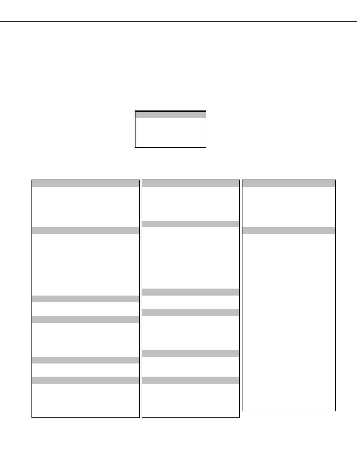
A. Option Menu Setup
Follow the steps below for the initial set-up:
1. Select the "MENU" display by pressing the "MENU" button once.
2. Press the number buttons "0", "3", "7", "0" in sequence to select the "OPTION MENU" display.
3. Press the "ADJUST" button to select "INITIAL."
4. Press "ENTER."
NOTE: At this time channel 3 is automatically selected.
B. Default Settings
MENU-0-3-7-0
OPTION MENU
Initial
Power Restore :OFF
DTV Port :Auto
Direct Key Mod :OFF
Memorize Channels Ant-A Air Lock by Time Off Magenta 50%
Input Assignment (V22) Lock Time N/A Red 50%
NetCommand® IR Setup (V22+) Unlock Time N/A Yell o w 50%
Clock Front Button Lock Off Green 50%
Language English V-Chip Cyan 50%
Energy Mode Low Blue 50%
V-Chip Off
Antenna-A On TV Rating TV-PG A/V Memory Reset Ant A
Antenna-B On FV-Fantasy Violence Allow TV Speakers (Internal) On
DTV YPrPb D-Sexual Dialog Allow Audio Output Variable
Component-1 Comp-1 L-Adult Language Allow
Component-2 C omp-2 S-Sexual Situati o n Allow TV Bass 50%
Input-1 Input-1 V-Violence Allow TV Treble 50%
Input-2 Input-2 Movie Rating PG TV Balance 50%
Input-3 Input-3 Programs Not Rated Allow TV Surround Off
MonLink M onLink TV Listen To Stereo
V-Chip Start Time 12:00am TV Level Sound Off
Language English V-Chip Stop Time 12:00am VIDEO SETTINGS
NetCommand
®
IR Setup
TV Contrast 100%
CLOCK M enu Color Balance TV Brightness 50%
Clock Setting Manual Timer TV Sharpness 50%
Clock Time --:-- Convergence TV Color 50%
Set Day Sunday Video Mute On TV Tint 50%
Time Zone N/A Black Enhancement On TV Color Temp High
Daylig ht Savings Time N /A TV Video Noise Standard
CAPTIONS Menu Ant-A Auto Color Correction Off TV Film Mode (Auto) On
Closed Captions In Mute PerfectColor™ TV VSM (V22+ Only) On
CC Background Gray Reset Color for Ant-A TV Volume 30%
CHANNEL EDIT Menu TIMER Menu PIP Source Ant A Ch 3
Antenna ANT-A Timer Off PIP Position Lower Right
Channel 003 Set Time 12:00 am POP Position Right Half
Memory Deleted Set Day Everyd ay
Format
Stretch
Name N/A Input Ant-A PIP/POP Format Dble Win
SQV N/A Channel 003
V-CHIP Hours
COLOR BALANCE Menu
V-CHIP LOCK Menu
V-CHIP Menu
ADVANCED FEATURES Menu
MAIN MENU DEFAULT SETTINGS
AUDIO/VIDEO SETTINGS Menu
PerfectColor™
AUDIO SETTINGS
SETUP Menu
INPUT ASSIGNMENT Menu (V2 2)
Welcome to NetCommand® IR (V22+)
 Loading...