


 Loading...
 MITSUBISHIELECTRIC
WS-48613
2003
Service Manual
PROJECTION TELEVISION
V23 / V23+ / V23++ / V23+++ CHASSIS
V23 MODELS |
V23+ MODELS |
WS-48513 |
WS-48613 |
WS-55513 |
WS-55613 |
WS-65513 |
WS-65613 |
WS-73513 |
|
V23++ MODELS |
V23+++ MODELS |
WS-65713 |
WS-55813 |
WS-73713 |
WS-65813 |
CAUTION:
Before servicing this chassis, it is important that the service person read the "SAFETY PRECAUTIONS" and "PRODUCT SAFETY NOTICE" contained in this manual.
SPECIFICATIONS
• Power Input |
: AC 120V, 60Hz |
|
• Power Usage |
: 275W |
|
|
300W [WS-65813/ WS-73513/ |
|
|
WS-73713 only] |
|
• Frequency Range |
: VHF |
54 ~ 470MHz |
|
UHF |
470 ~ 806MHz |
• Antenna Input |
: VHF/UHF 75Ω unbalanced |
|
|
2 - NTSC |
|
|
1 -ATV/QAM |
|
• CRT Size |
: [7 inches] |
|
|
: [9 inches] WS-65813/ WS-73513/ |
|
|
WS-73713 only |
|
• High Voltage |
: 32.0kV (at 0A) |
|
•Cabinet Weight and Dimensions (Refer to page 5)
•Speakers (8 Ohms 10W)
: 2-5" full range |
[WS-48513 / WS-48613] |
|
: 2-6" full range |
[WS-55513 |
/ WS-65513 / WS-73513] |
: 2-6" coaxials |
[WS-55613 |
/ WS-65613] |
: 2-6" woofers/ |
[WS-65713 |
/ WS-73713] |
2-1.5" tweeters |
|
|
: 2-5"x7" coaxial |
[WS-55813 |
/ WS-65813] |
.
• Design specifications are subject to change without notice.
• Input Level : VIDEO IN JACK (RCA Type) 1.0Vp-p 75Ω unbalanced
:AUDIO IN JACK (RCA Type) -4.7dBm 43kΩ unbalanced
:S-VIDEO IN JACK (Y/C separate type)
Y:1.0 Vp-p C:0.286Vp-p(BURST) 75Ω unbalanced
:COMP / Y, Cr, Cb (RCA Type)
Y:1.0 Vp-p Cr, Cb: 700mVp-p
:ATV / Y(G), Pr(R), Pb(B), H, V
Y:1.0Vp-p with sync 75Ω (BNC) Pr, Pb: 700mV 75Ω
H, V: 3.0Vp-p 75Ω
:VGA / R,G,B,V,H (15 pin D)
•Output Level : VIDEO OUT JACK (RCA Type)
1.0Vp-p 75Ω unbalanced
|
: AUDIO OUT JACK (RCA Type) |
|
-4.7dBm 4.7kΩ unbalanced |
• Digital |
: IEEE-1394 I/O Jacks |
Interface |
: AC-3 Digtal Audio Output |
|
: MonitorLinkTM/DVI |
|
: MonitorLinkTM Control/RS-232C |
|
: 4 Memory Card Reader Inputs |
MITSUBISHI DIGITAL ELECTRONICS AMERICA, INC.
9351 Jeronimo Road, Irvine, CA 92618-1904
Copyright © 2003 Mitsubishi Digital Electronics America, Inc.
All Rights Reserved

MODELS: WS-48513 / WS-48613 / WS-55513 / WS-55613 / WS-55813 / WS-65513 / WS-65613 / WS-65713 / WS-65813 / WS-73513 / WS-73713
CONTENTS |
|
INTRODUCTION .................................................................................................................................. |
5 |
CABINET WEIGHT & DIMENSIONS ................................................................................................... |
5 |
PRODUCT SAFETY NOTICE ............................................................................................................... |
5 |
DISASSEMBLY PROCEDURES .......................................................................................................... |
7 |
WS-48513 / WS-48613 |
|
Front Cabinet Components ..................................................................................................... |
7 |
Rear Cabinet Components ...................................................................................................... |
8 |
WS-55513 / WS-55613 / WS-65513 / WS-65613 |
|
Front Cabinet Components ..................................................................................................... |
9 |
Rear Cabinet Components .................................................................................................... |
10 |
WS-55813 |
|
Front Cabinet Components .................................................................................................... |
11 |
Rear Cabinet Components .................................................................................................... |
12 |
WS-65813 |
|
Front Cabinet Components ................................................................................................... |
13 |
Rear Cabinet Components .................................................................................................... |
14 |
WS-73513 |
|
Front Cabinet Components ................................................................................................... |
15 |
WS-65713 / WS-73713 |
|
Front Cabinet Components ................................................................................................... |
16 |
WS-65713 / WS-73513 / WS-73713 |
|
Rear Cabinet Components .................................................................................................... |
17 |
SERVICING THE LENTICULAR LENS AND FRESNEL SCREEN ..................................................... |
18 |
Removal of the Lenticular Screen and Fresnel Lens |
|
WS-48513 / WS-48613 ......................................................................................................... |
18 |
WS-55513 / WS-55613 / WS-65513 / WS-65613 ................................................................. |
19 |
WS-55813 / WS-65813 ......................................................................................................... |
20 |
WS-65713 / WS-73713 ......................................................................................................... |
21 |
WS-73513 ............................................................................................................................. |
22 |
All Models |
|
Installation of the Lenticular Screen and Fresnel Lens .......................................................... |
23 |
DIAMONDSHIELDTM Removal and Installation .............................................................................. |
24 |
CABINET SEPARATION PROCEDURES |
|
WS-65813 ...................................................................................................................................... |
25 |
WS-65513 / WS-65613 and WS-65713 / WS-73513 ...................................................................... |
26 |
SERVICING PCBs ............................................................................................................................. |
27 |
Chassis Removal ........................................................................................................................... |
27 |
PCB Locations ............................................................................................................................... |
27 |
Major Parts Locations .................................................................................................................... |
28 |
DM Module Replacement ............................................................................................................... |
28 |
CRT REPLACEMENT ........................................................................................................................ |
29 |
CRT Removal ................................................................................................................................. |
29 |
CRT Installation .............................................................................................................................. |
28 |
ELECTRICAL ADJUSTMENTS.......................................................................................................... |
32 |
Equipment and Initial Setup ........................................................................................................... |
32 |
Page 3

MODELS: WS-48513 / WS-48613 / WS-55513 / WS-55613 / WS-55813 / WS-65513 / WS-65613 / WS-65713 / WS-65813 / WS-73513 / WS-73713
LED Indicator Diagnostics .............................................................................................................. |
34 |
Remote Control Operational Mode ................................................................................................. |
34 |
Circuit Adjustment Mode ................................................................................................................ |
35 |
Service Mode Reset ....................................................................................................................... |
36 |
Convergence Adjustment Mode ...................................................................................................... |
36 |
Adjustment Items List .................................................................................................................... |
38 |
Adjustment Procedures .................................................................................................................. |
41 |
Test Point Locations ............................................................................................................. |
41 |
Main / Sub Y Level & & HV Regulation ................................................................................. |
42 |
Main / Sub Color Level & CRT Cutoff ..................................................................................... |
43 |
White Balance (NTSC) & White Balance (HD) ...................................................................... |
44 |
Black Level & Sub Contrast .................................................................................................. |
45 |
Dynamic Focus Presets & Lens Focus ................................................................................ |
46 |
Alignment Magnet / Electrostatic Focus & Charactrer Position ............................................ |
47 |
Geometry Presets ................................................................................................................. |
48 |
Deflection Geometry Adjustments ......................................................................................... |
49 |
Convergence Geometry Adjustments .................................................................................... |
50 |
Centering & Static Convergence ............................................................................................ |
51 |
Coarse Convergence Adjustments ........................................................................................ |
52 |
Fine Convergence Adjustments ............................................................................................. |
52 |
CHIP PARTS REPLACEMENT .......................................................................................................... |
54 |
REPLACEMENT PARTS .................................................................................................................... |
55 |
Parts Ordering ................................................................................................................................ |
55 |
Critical and Warranty Parts Designation ........................................................................................ |
55 |
Parts Tolerance Codes ................................................................................................................... |
55 |
Quick Reference List ...................................................................................................................... |
56 |
SERVICE PARTS LIST ..................................................................................................................... |
57 |
SCREEN ASSEMBLY PARTS LIST ................................................................................................... |
73 |
CIRCUITRY BLOCK DIAGRAMS ...................................................................................................... |
77 |
Page 4

MODELS: WS-48513 / WS-48613 / WS-55513 / WS-55613 / WS-55813 / WS-65513 / WS-65613 / WS-65713 /
WS-65813 / WS-73513 / WS-73713
INTRODUCTION
This service manual provides service instructions for the V23, V23+, v23++ and V23+++ PTV chassis types. The specific models for each chassis type are listed below. Service personnel should read this manual thoroughly before servicing these chassis.
V23 Chassis |
V23+ Chassis |
V23++ Chassis |
V23+++ Chassis |
WS-48513 |
WS-48613 |
WS-65713 |
WS-55813 |
WS-55513 |
WS-55613 |
WS-73713 |
WS-65813 |
WS-65513 |
WS-65613 |
|
|
WS-73513 |
|
|
|
|
|
|
|
This service manual includes:
1.Assembly and disassembly instructions for the front and rear cabinet components.
2.Servicing of the Lenticular Screen and Fresnel Lens.
3.Servicing printed circuit boards (PCBs).
4.CRT replacement procedure.
5.Electrical adjustments.
6.Chip parts replacement procedures.
7.Circuit path diagrams.
The parts list section of this service manual includes:
1.Cabinet and screen parts.
2.Electrical parts.
Schematic and block diagrams of the above listed models are included in this service manual for better understanding of the circuitry. PCB drawings are also included for easy location of parts and test points.
Cabinet Weight and Dimensions
Model |
Weight |
Height |
Width |
Depth |
Spkrs |
WS-48513 |
175 lbs |
49 in |
44.5 in. |
24 in. |
5" 10W |
WS-48613 |
180.5 lbs |
49 in |
45 in |
24.1 in |
5" 10W |
WS-55513 |
230 lbs |
50.3 in |
50.5 in |
25.4 in |
6" 10W |
WS-55613 |
250 lbs |
50.5 in |
50.5 in |
28 in |
6" 10W |
WS-55813 |
200 lbs |
50.5 in |
50.5 in |
28 in |
5"&7" |
WS-65513 |
333 lbs |
62 in |
59 in |
28 in |
6" 10W |
WS-65613 |
333 lbs |
62 in |
59 in |
28 in |
6" 10W |
WS-65713 |
350 lbs |
61.5 in |
58 in |
28.5 in |
6"&1.5" |
WS-65813 |
251 lbs |
62 in |
59 in |
28 in |
6" 10W |
WS-73513 |
374 lbs |
66 in |
66 in |
30 in |
6" 10W |
WS-73713 |
410 lbs |
66 in |
65 in |
30 in |
6"&1.5" |
• Weight and Dimensions ar approximate
PRODUCT SAFETY NOTICE
Many electrical and mechanical parts in television receivers have special safety related characteristics. These characteristics are often not evident from visual inspection nor can the protection afforded by them necessarily be obtained by using replacement components rated for higher voltage, wattage, etc.
Replacement parts which have special safety characteristics are identified in this service manual.
Electrical components having such features are identified in the parts data base and by bold
type in the parts list of this service manual. The replacement for any safety part should be identical in value and characteristics.
Page 5

MODELS: WS-48513 / WS-48613 / WS-55513 / WS-55613 / WS-55813 / WS-65513 / WS-65613 / WS-65713 /
WS-65813 / WS-73513 / WS-73713
SAFETY PRECAUTIONS
NOTICE: Observe all cautions and safety related notes located inside the receiver cabinet and on the receiver chassis.
WARNING:
1.Operation of this receiver outside the cabinet or with the cover removed presents a shock hazard from the receiver's power supplies. Work on the receiver should not be attempted by anyone who is not thoroughly familiar with the precautions necessary when working on high voltage equipment.
2.Do not install, remove or handle the picture tubes in any manner unless shatterproof goggles are worn. People not so equipped should be kept away while the picture tube is being handled. Keep the picture tube away from the body while handling.
3.When service is required, observe the original lead dress. Extra precaution should be taken to assure correct lead dress in the high voltage area. Where a short-circuit has occurred, replace those components that indicate evidence of overheating.
X-Radiation warning
The surface of the cathode ray tubes (CRTs) may generate X-Radiation, so take proper precautions when servicing. It is recommended that a lead apron be used for shielding while handling the CRT. Use this method if possible.
When replacing the CRTs, use only the designated replacement part since it is a critical component with regard to X-Radiation. High voltage must be set as prescribed under the section titled Electrical Adjustments.
Leakage current check
Before returning the receiver to the customer, it is recommended that leakage current be measured according to the following methods.
1.Cold Check
With the alternating current (AC) plug removed from the AC source, place a jumper across the two AC plug prongs. Connect one lead of an ohm meter to the AC plug and touch the other lead to each exposed metal part (i.e. antennas, handle bracket, metal cabinet, screw heads, metal overlay, control shafts, etc.), particularly any exposed metal part that has a return path to the chassis. The resistance of the exposed metal parts having a return path to the chassis should be a minimum of 1Mega Ohm. Any resistance below this value indicates an abnormal condition and requires corrective action.
2.Hot Check ...Use the circuit shown below to perform the hot check test.
1.Keep switch S1 open and connect the receiver to the measuring circuit. Immediately after connection, and with the switching devices of the receiver in their operating positions, measure the leakage current for both positions of switch S2.
2.Close switch S1, energizing the receiver. Immediately after closing switch S1, and with the switching devices of the receiver in their operating positions, measure the leakage current for both positions of switch S2. Repeat the current measurements of items 1 and 2 after the receiver has reached thermal stabilization. The leakage current must not exceed 0.5 milliampere (mA).
Page 6
MODELS: WS-48513 / WS-48613 / WS-55513 / WS-55613 / WS-55813 / WS-65513 / WS-65613 / WS-65713 /
WS-65813 / WS-73513 / WS-73713
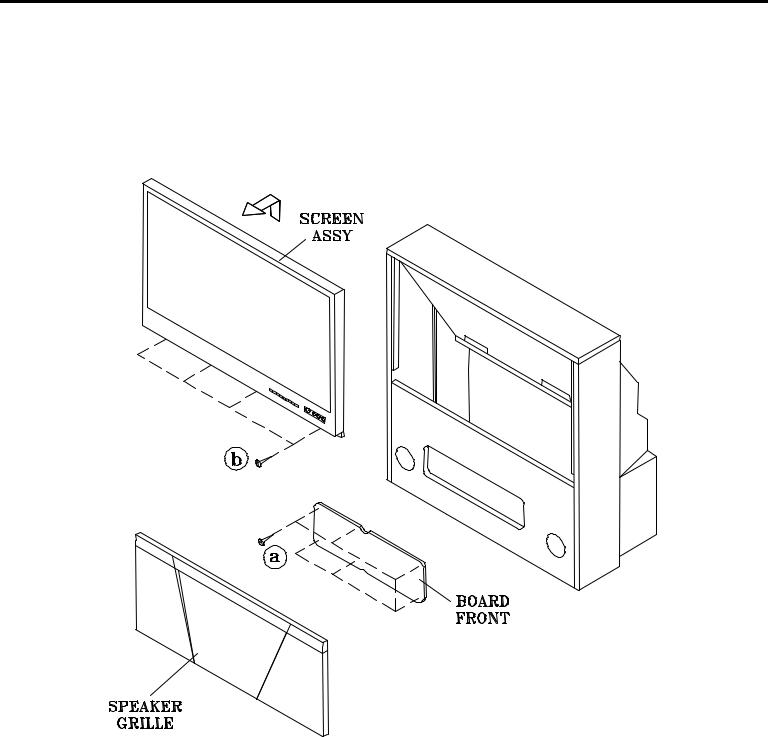
CABINET DISASSEMBLY (FRONT VIEW)
WS-48513 / WS-48613
*Refer to the Parts List for Part Numbers
Front Cabinet Disassembly
1.Remove the Speaker Grille by pulling forward.
2.Remove the Board Front by removing 6 screws (a).
3.Remove 4 screws (b) holding the Screen Assembly.
4.Lift the Screen Assembly up and away from the cabinet.
Page 7

MODELS: WS-48513 / WS-48613 / WS-55513 / WS-55613 / WS-55813 / WS-65513 / WS-65613 / WS-65713 /
WS-65813 / WS-73513 / WS-73713
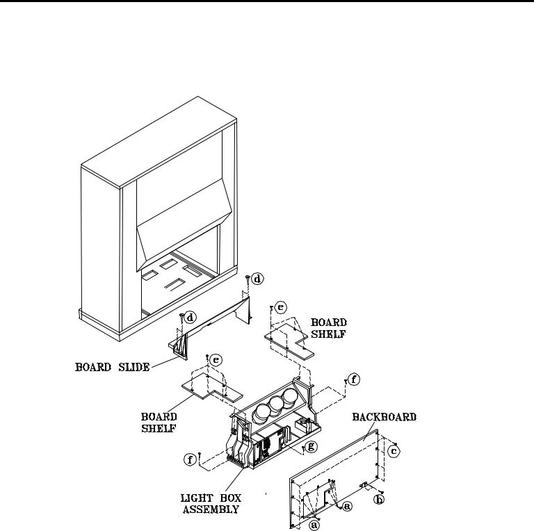
CABINET DISASSEMBLY (REAR VIEW)
WS-48513 / WS-48613
*Refer to the Parts List for Part Numbers
Rear Cabinet Disassembly
1.Remove the Back Board by removing 7 screws (a), 2 screws (b) and 8 screws (c).
2.Remove the Back Cover by removing 8 screw (d).
3 Remove 4 screws (e) to remove the Board Slide.
4.Remove screws (f) to remove the Board Shelves.
5.Remove screw (g) holding the chassis.
6.Remove 4 screws (h) securing the Light Box Assembly.
7.Be certain that all cables and connectors between the Light Box Assembly and external items are disconnected (e.g. speaker plugs, etc.), including the USB and 1394 connectors from the Card Reader to the DM Module.
8.Slide the Light Box Assembly from the cabinet.
Page 8

MODELS: WS-48513 / WS-48613 / WS-55513 / WS-55613 / WS-55813 / WS-65513 / WS-65613 / WS-65713 /
WS-65813 / WS-73513 / WS-73713
CABINET DISASSEMBLY (FRONT VIEW)
WS-55513 / WS-65513 / WS-55613 / WS-65613
*Refer to the Parts List for Part Numbers
Front Cabinet Disassembly
1.Remove the Speaker Grille by pulling forward.
2.Remove the Board Front by removing 6 screws (a).
3.Remove the 5 screws (b) holding the Screen Assembly.
4.Unplug the cables to the Control Panel and the Front Panel Inputs.
4. Lift the Screen Assembly up and away from the cabinet.
Page 9
MODELS: WS-48513 / WS-48613 / WS-55513 / WS-55613 / WS-55813 / WS-65513 / WS-65613 / WS-65713 /
WS-65813 / WS-73513 / WS-73713
CABINET DISASSEMBLY (REAR VIEW)
WS-55513 / WS-65513 / WS-55613 / WS-65613
*Refer to the Parts List for Part Numbers
Rear Cabinet Disassembly
1.Remove screws (a), (b) and (c) holding the Back Board.
2.Remove 4 screws (d) holding the Board Slide
3.Remove the 4 screws (e) holding each Board Shelf.
4.Remove screw (g) holding the chassis.
5.Remove 4 screws (f) securing the Light Box Assembly.
6.Be certain that all cables and connectors between the Light Box Assembly and external items are disconnected (e.g. speaker plugs, etc.), including the USB and 1394 cables from the Card Reader.
7.Slide the Light Box out the rear of the Cabinet.
Page 10
MODELS: WS-48513 / WS-48613 / WS-55513 / WS-55613 / WS-55813 / WS-65513 / WS-65613 / WS-65713 /
WS-65813 / WS-73513 / WS-73713
CABINET DISASSEMBLY (FRONT VIEW)
WS-55813
*Refer to the Parts List for Part Numbers
Front Cabinet Disassembly
1.Remove the Speaker Grille by pulling forward.
2.Remove 2 screws (a) securing the Front Panel.
3.Slide the Front Panel 1/2 inch to the right, then pull away from the TV.
4.Remove 4 screws (b) to remove the Board Front.
5.Unplug the the connectors to the Control Panel.
6.Remove the 4 screws (c) securing the Screen Assembly.
7.Lift the Screen Assembly up and away from the cabinet.
Page 11

MODELS: WS-48513 / WS-48613 / WS-55513 / WS-55613 / WS-55813 / WS-65513 / WS-65613 / WS-65713 /
WS-65813 / WS-73513 / WS-73713
CABINET DISASSEMBLY (REAR VIEW)
WS-55813
*Refer to the Parts List for Part Numbers
Rear Cabinet Disassembly
1.Remove screws (a), (b) and (c) holding the Back Board.
2.Remove 4 screws (d) holding the Board Slide
3.Remove the 5 screws (e) holding each Board Shelf.
4.Remove screw (f) and 3 screws (g) securing the Light Box Assembly.
5.Be certain that all cables and connectors between the Light Box Assembly and external items are disconnected (e.g. speaker plugs, etc.), including the USB and 1394 cables from the Card Reader..
6.Slide the Light Box out the rear of the Cabinet.
Page 12

MODELS: WS-48513 / WS-48613 / WS-55513 / WS-55613 / WS-55813 / WS-65513 / WS-65613 / WS-65713 /
WS-65813 / WS-73513 / WS-73713
CABINET DISASSEMBLY (FRONT VIEW)
WS-65813
*Refer to the Parts List for Part Numbers
Front Cabinet Disassembly
1.Remove the Speaker Grille by pulling forward.
2.Remove 2 screws (a) securing the Front Panel.
3.Slide the Front Panel 1/2 inch to the right, then pull away from the TV.
4.Remove 6 screws (b) to remove the Board Front.
5.Unplug the connectors to the Screen Assembly.
6.Remove the 4 screws (c) securing the Screen Assembly.
7.Lift the Screen Assembly up and away from the cabinet.
Page 13

MODELS: WS-48513 / WS-48613 / WS-55513 / WS-55613 / WS-55813 / WS-65513 / WS-65613 / WS-65713 /
WS-65813 / WS-73513 / WS-73713
CABINET DISASSEMBLY (REAR VIEW)
WS-65813
*Refer to the Parts List for Part Numbers
Rear Cabinet Disassembly
1.Remove screws (a), (b) and (c) holding the Back Board.
2.Remove the 2 screws (d) holding the Board Slide.
3.Remove the 3 screws (e) and 2 screws (f) securing the Light Box Assembly.
4.Disconnect cabling to the front panel (Control Panel, Speakers, Inputs, etc.), including the USB and 1394 cables from the Card Reader to the DM Module.
4. Slide the Light Box out the rear of the Cabinet.
Page 14
MODELS: WS-48513 / WS-48613 / WS-55513 / WS-55613 / WS-55813 / WS-65513 / WS-65613 / WS-65713 /
WS-65813 / WS-73513 / WS-73713
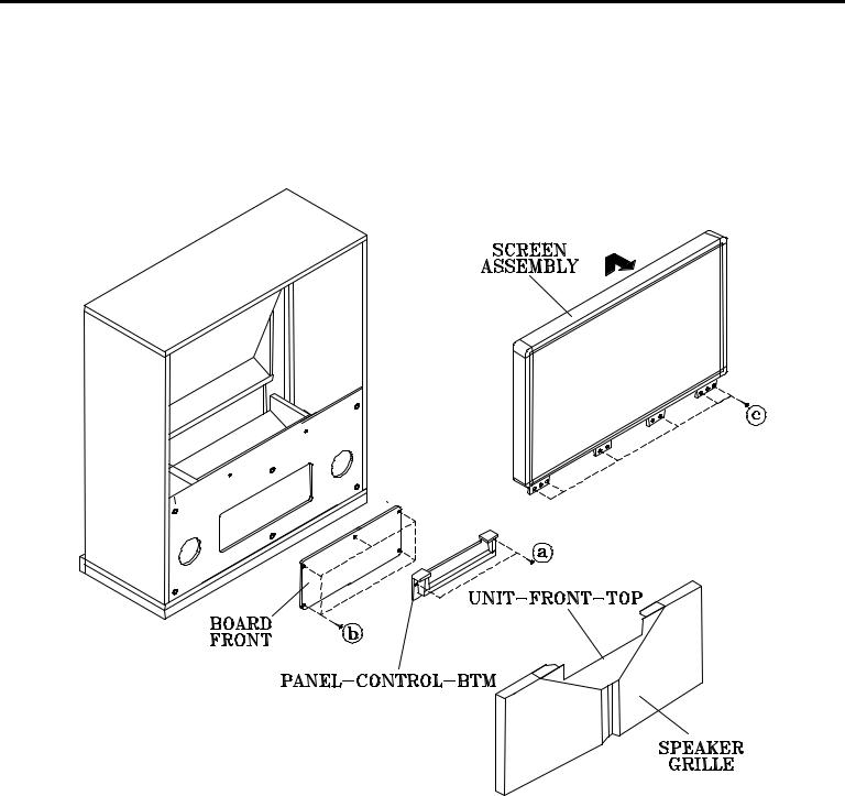
CABINET DISASSEMBLY (FRONT VIEW)
WS-73513
*Refer to the Parts List for Part Numbers
Front Cabinet Disassembly
1.Remove the Speaker Grille by pulling forward.
2.Remove 2 screws (a) securing the PENEL-CONTROL-BTM
3.Remove 5 screws (b) to remove the Board Front.
4.Remove the 6 screws (c) securing the Screen Assembly.
5.Lift the Screen Assembly up and away from the cabinet.
Page 15

MODELS: WS-48513 / WS-48613 / WS-55513 / WS-55613 / WS-55813 / WS-65513 / WS-65613 / WS-65713 /
WS-65813 / WS-73513 / WS-73713
CABINET DISASSEMBLY (FRONT VIEW)
WS-65713 / WS-73713
*Refer to the Parts List for Part Numbers
Front Cabinet Disassembly
1.Remove the 2 Speaker Grilles and the Unit Front by pulling forward.
2.Remove 6 screws (b) securing the Board Front.
3.Remove two screws (a) to remove the Control Panel
4.Remove the 4 screws (c) securing the Screen Assembly.
7. Lift the Screen Assembly up and away from the cabinet.
Page 16
MODELS: WS-48513 / WS-48613 / WS-55513 / WS-55613 / WS-55813 / WS-65513 / WS-65613 / WS-65713 /
WS-65813 / WS-73513 / WS-73713
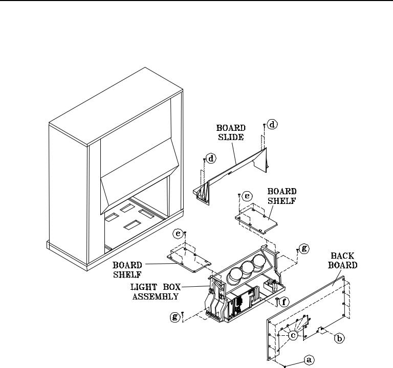
CABINET DISASSEMBLY (REAR VIEW)
WS-65713 / WS-73513 / WS-73713
*Refer to the Parts List for Part Numbers
Rear Cabinet Disassembly
1. |
Remove 8 screws (a), 2 screws(b) and 9 screws (c) holding the Back Board. |
2. |
Remove the 4 screws (d) holding the Board Slide. |
3. |
Rmove 4 screws (e) securing each Board Shelf. |
3. |
Remove the 4 screws (g) and a screw (f) securing the Light Box Assembly. |
4. |
Disconnect cabling to the front panel (Control Panel, Speakers, Inputs, etc.), including the USB and 1394 |
|
cables from the Card Reader. |
4. |
Slide the Light Box out the rear of the Cabinet. |
Page 17
MODELS: WS-48513 / WS-48613 / WS-55513 / WS-55613 / WS-55813 / WS-65513 / WS-65613 / WS-65713 /
WS-65813 / WS-73513 / WS-73713
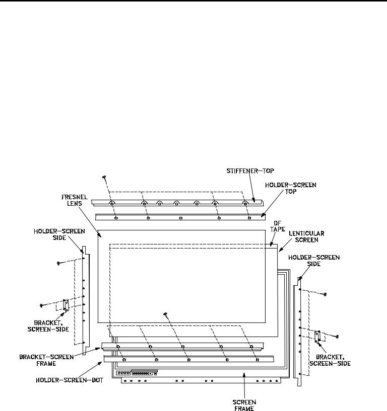
SERVICING THE LENTICULAR SCREEN AND FRESNEL LENS
CAUTION: Wear gloves when handling the Lenticular Screen and Fresnel Lens.
This prevents cuts and finger prints. Do not place Fresnel Lens in the sun. This may cause fire and heat related injuries.
WS-48513 / 48613
Lenticular Screen and Fresnel Lens Removal
1.Remove the screen assembly shown in the Cabinet Disassembly procedure.
2.Remove the Top, Bottom and Side Screen Holders.
3.Carefully lift the Lenticular Screen and Fresnel Lens combination from the Screen Frame assembly.
Note: When separating the Lenticular Screen from the Fresnel Lens, use caution while prying the Screen and Lens apart. Use a slot type screw driver, and remove the pressure sensitive double sided tape.
Page 18

MODELS: WS-48513 / WS-48613 / WS-55513 / WS-55613 / WS-55813 / WS-65513 / WS-65613 / WS-65713 /
WS-65813 / WS-73513 / WS-73713
SERVICING THE LENTICULAR SCREEN AND FRESNEL LENS
WS-55513 / WS-55613 / WS-65513 / WS-65613
CAUTION: Wear gloves when handling the Lenticular Screen and Fresnel Lens.
This prevents cuts and finger prints. Do not place Fresnel Lens in the sun. This may cause fire and heat related injuries.
1b. Lenticular Screen and Fresnel Lens Removal
1.Remove the screen assembly as shown in the Cabinet Disassembly procedure.
2.Remove the HOLDER-SCREEN-BOTTOM.
3.Carefully slide the Lenticular Screen and Fresnel Lens combination from the upper Screen Frame Assembly.
Note: When separating the Lenticular Screen from the Fresnel Lens, use caution while prying the Screen and Lens apart. Use a slot type screw driver, and remove the pressure sensitive double sided tape.
1b. Installing the Fresnel Lens and Lenticular Screen
1.Insert the Lenticular Screen and Fresnel Lens combination into the upper Screen Frame.
2.Install the HOLDER-SCREEN-BOTTOM, install the end screws first. .
Page 19

MODELS: WS-48513 / WS-48613 / WS-55513 / WS-55613 / WS-55813 / WS-65513 / WS-65613 / WS-65713 /
WS-65813 / WS-73513 / WS-73713
SERVICING THE LENTICULAR SCREEN AND FRESNEL LENS
CAUTION: Wear gloves when handling the Lenticular Screen and Fresnel Lens.
This prevents cuts and finger prints. Do not place Fresnel Lens in the sun. This may cause fire and heat related injuries.
WS-55813 / WS-65813
Lenticular Screen and Fresnel Lens Removal
1.Remove the screen assembly shown in the Cabinet Disassembly procedure.
2.Remove the Screen Frame top section by removing 4 screws (a).
3.Carefully grasp the Lenticular Screen and Fresnel Lens combination and pull upward and out of the Screen Frame Assembly.
Note: When separating the Lenticular Screen from the Fresnel Lens, use caution while prying the Screen and Lens apart. Use a slot type screw driver, and remove the pressure sensitive double sided tape.
Page 20
MODELS: WS-48513 / WS-48613 / WS-55513 / WS-55613 / WS-55813 / WS-65513 / WS-65613 / WS-65713 /
WS-65813 / WS-73513 / WS-73713
SERVICING THE LENTICULAR SCREEN AND FRESNEL LENS
CAUTION: Wear gloves when handling the Lenticular Screen and Fresnel Lens.
This prevents cuts and finger prints. Do not place Fresnel Lens in the sun. This may cause fire and heat related injuries.
WS-65713 / WS-73713
Lenticular Screen and Fresnel Lens Removal
1.Remove the screen assembly shown in the Cabinet Disassembly procedure.
2.Remove the Screen Frame bottom section by removing 4 screws (a).
3.Carefully grasp the Lenticular Screen and Fresnel Lens combination and pull downward and out of the Screen Frame Assembly.
Note: When separating the Lenticular Screen from the Fresnel Lens, use caution while prying the Screen and Lens apart. Use a slot type screw driver, and remove the pressure sensitive double sided tape.
Page 21

MODELS: WS-48513 / WS-48613 / WS-55513 / WS-55613 / WS-55813 / WS-65513 / WS-65613 / WS-65713 /
WS-65813 / WS-73513 / WS-73713
SERVICING THE LENTICULAR SCREEN AND FRESNEL LENS
CAUTION: Wear gloves when handling the Lenticular Screen and Fresnel Lens.
This prevents cuts and finger prints. Do not place Fresnel Lens in the sun. This may cause fire and heat related injuries.
WS-73513
Lenticular Screen and Fresnel Lens Removal
1.Remove the screen assembly shown in the Cabinet Disassembly procedure.
2.Remove the Screen Frame top section by removing 4 screws (a).
3.Carefully grasp the Lenticular Screen and Fresnel Lens combination and pull upward and out of the Screen Frame Assembly.
Note: When separating the Lenticular Screen from the Fresnel Lens, use caution while prying the Screen and Lens apart. Use a slot type screw driver, and remove the pressure sensitive double sided tape.
Page 22
MODELS: WS-48513 / WS-48613 / WS-55513 / WS-55613 / WS-55813 / WS-65513 / WS-65613 / WS-65713 /
WS-65813 / WS-73513 / WS-73713
SERVICING THE LENTICULAR SCREEN AND FRESNEL LENS
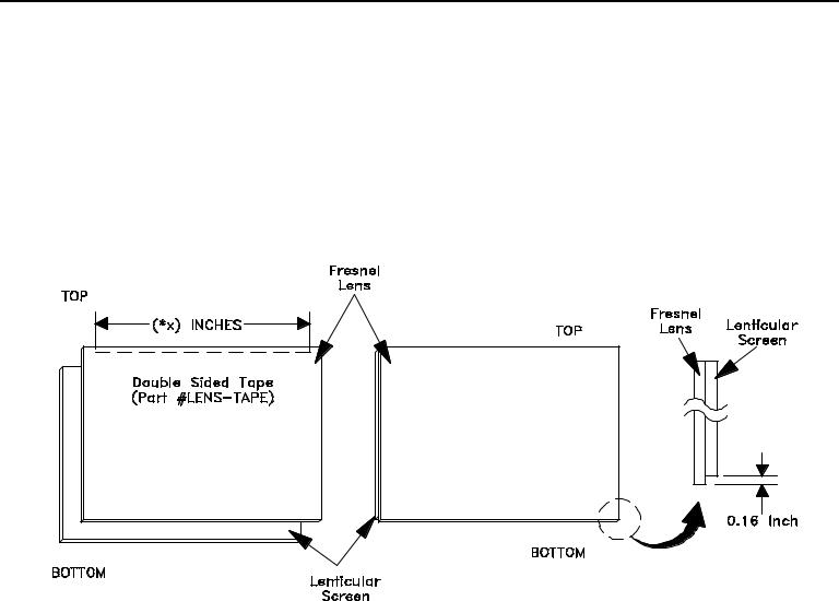
2. Lenticular Screen and Fresnel Lens Installation.
Note: Store the Lenticular Screen and Fresnel Lens in a cool dry place. High humidity may deform the Lenticular Screen and Fresnel Lens.
1.Apply double coated tape (Part # LENS-TAPE) along the top front edge of the Fresnel Lens as shown below. Refer to the Table below for proper tape length.
2.Place the Fresnel Lens on top of the Lenticular Screen and apply pressure at the top edge to bond them together as shown below.
Model |
Screen |
Tape |
|
Size |
Length |
||
|
|||
WS-48513 |
48" |
41,8" |
|
WS-48613 |
" |
" |
|
WS-55513 |
55" |
47.8" |
|
WS-55613 |
" |
" |
|
WS-55813 |
" |
" |
|
WS-65513 |
65" |
56.5" |
|
WS-65613 |
" |
" |
|
WS-65713 |
" |
" |
|
WS-65813 |
" |
" |
|
WS-73513 |
73" |
63.5" |
|
WS-73713 |
" |
" |
Page 23
MODELS: WS-48513 / WS-48613 / WS-55513 / WS-55613 / WS-55813 / WS-65513 / WS-65613 / WS-65713 /
WS-65813 / WS-73513 / WS-73713
SERVICING THE DIAMONDSHIELD™
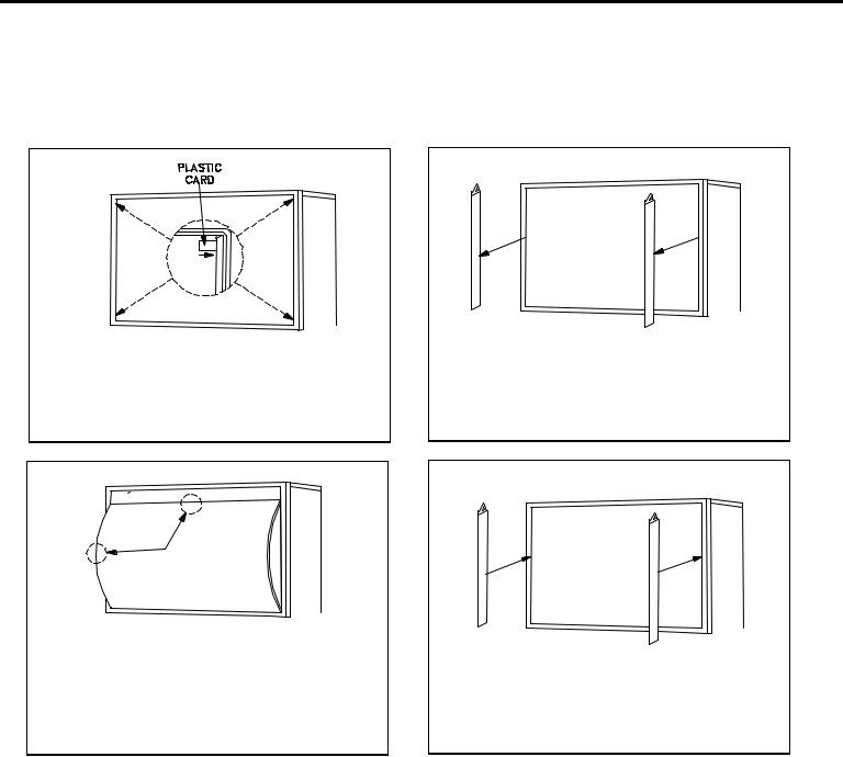
1. DiamondShield™ Removal Procedure
The appropriate disassembly procedure given below.
Note: Wear gloves when handling the DiamondShield™ to prevent finger prints.
1.Gently insert a small plastic card (such as a credit card or a plastic putty knfe) between the DiamondShield™ and one end of the clip to pry the clip loose.
2. Remove both clips by pulling them toward you.
3.Carefully insert the small plastic card (or plastic putty knife) into the gap at the side/center point
of the Shield and pull the Shield slightly away |
4. Reinstall the two clips |
from the unit. Place your hands at the points |
|
shown and gently bow the Shield toward you |
|
and remove from the unit. |
|
2. DiamondShield™ Installation Procedure
*(See the Parts List for DiamondShield™ part numbers)
To install the DiamondShieldTM, reverse the above Removal Procedure.
Page 24

MODELS: WS-48513 / WS-48613 / WS-55513 / WS-55613 / WS-55813 / WS-65513 / WS-65613 / WS-65713 /
WS-65813 / WS-73513 / WS-73713
CABINET SEPARATION
Mitsubishi 65 and 73 inch Projection TVs have been assembled in two pieces. These pieces may be separated for easier delivery and setup. The cabinet separation procedure requires two persons and varies between models.
WS-65813 Cabinet Separation Procedure
Figure 1
1.Remove the Speaker Grille by pulling forward.
2.Remove the two Front Cover screws (a).
3.To remove the Front Cover, slide to the right approximately 1/2”, then pull away from the TV.
Figure 2
4.Remove Screw (b) from the front board.
5.Disconnect the LF connector.
Figure 3
6.Remove screw (c) on each side of the cabinet.
7.Remove the plastic cover on each side.
Figure 4
8. Slide the top of the cabinet top forward.
Figure 5
9.Carefully lift the cabinet top until the interlock tabs clear the cabinet bottom
Figure 6
10.Carefully place the cabinet top on the floor as shown.
Figure 1
Figure 2
Figure 3 |
Figure 4 |
Figure 5
Figure 6
Page 25

MODELS: WS-48513 / WS-48613 / WS-55513 / WS-55613 / WS-55813 / WS-65513 / WS-65613 / WS-65713 /
WS-65813 / WS-73513 / WS-73713
CABINET SEPARATION PROCEDURE
(WS-65513 / WS-65613 and WS-65713 / WS-73513 / WS-73713)
WS-65513 / WS-65613 Cabinet Separation Precedure
1. Pull the Speaker Grill from the cabinet.
2. Unplug the CC and ZF connectore
3.Remove 4 plastic covers and screws (a) from each side of the cabinet.
4.Carefully lift the cabinet top and place it on
the floor.
5. Place the cabinet bottom in the desired location.
6. Reverse the procedure and mount the cabinet top on the cabinet bottom.
WS-65513
WS-65613
WS-65713 / WS-73513 / WS-73713 Cabinet Separation Precedure
1. Remove the 4 screw covers (a).
2. Remove 4 screws (b) securing the top and bottom cabinet sections .
3. Carefully lift the cabinet top and place it on the floor.
4. Place the cabinet bottom in the desired location.
5.Reverse the procedure and mount the cabinet top on the cabinet bottom.
WS-65713
WS-73513
WS-73713
Page 26
Loading...