


 Loading...
DLPTM Display Wall Cube /
LCD Display Wall
Seventy Series
Set-up Manual
REV. 1.3
January 29, 2010

|
|
|
|
|
|
|
|
|
|
|
|
|
|
Table of Contents |
|
|||
1 |
OVERVIEW............................................................................................................................................................. |
4 |
||||||||||||||||
|
1.1 |
Product lineup ................................................................................................................................................................................ |
4 |
|||||||||||||||
|
1.1.1 |
Main Products ............................................................................................................................................................................. |
4 |
|||||||||||||||
|
1.1.2 |
Optional products...................................................................................................................................................................... |
5 |
|||||||||||||||
|
1.2 |
Flowchart.......................................................................................................................................................................................... |
6 |
|||||||||||||||
|
1.3 |
Basic operation............................................................................................................................................................................... |
8 |
|||||||||||||||
|
1.3.1 |
Remote control unit................................................................................................................................................................... |
8 |
|||||||||||||||
|
1.3.2 |
Operation mode ......................................................................................................................................................................... |
9 |
|||||||||||||||
|
1.3.3 |
Menus.......................................................................................................................................................................................... |
10 |
|||||||||||||||
|
1.4 |
Control panel................................................................................................................................................................................. |
12 |
|||||||||||||||
2 |
CUBE INSTALLATION ( |
CUBE |
)............................................................................................................................. |
|
|
|
|
|
|
|
13 |
|||||||
|
2.1 |
Safety precaution......................................................................................................................................................................... |
13 |
|||||||||||||||
|
2.2 |
Preparation .................................................................................................................................................................................... |
14 |
|||||||||||||||
|
2.2.1 |
Accessories ................................................................................................................................................................................. |
14 |
|||||||||||||||
|
2.2.2 |
Input boards installation........................................................................................................................................................ |
14 |
|||||||||||||||
|
2.2.3 Front attachment in 80” cabinet .......................................................................................................................................... |
15 |
||||||||||||||||
|
2.3 |
Engine embedding ..................................................................................................................................................................... |
16 |
|||||||||||||||
|
2.3.1 |
|
Rear |
............................................................................................................................................................................................ |
|
|
|
|
|
|
|
|
|
|
|
16 |
||
|
|
|
|
|
|
|
|
|
|
|
|
|
|
|
|
|||
|
2.3.2 |
|
Front |
.......................................................................................................................................................................................... |
|
|
|
|
|
|
|
|
|
|
17 |
|||
|
2.4 |
Cube stacking ............................................................................................................................................................................... |
18 |
|||||||||||||||
|
2.4.1 |
Screen demounting ................................................................................................................................................................. |
18 |
|||||||||||||||
|
2.4.2 Base stands and cubes assembling ..................................................................................................................................... |
19 |
||||||||||||||||
|
2.4.3 Screen mounting and open/close ( |
Front |
) ........................................................................................................................ |
20 |
||||||||||||||
|
2.4.4 |
Screen gaps adjustment......................................................................................................................................................... |
21 |
|||||||||||||||
|
2.4.5 Fixing to the wall and floor .................................................................................................................................................... |
22 |
||||||||||||||||
3 LCD PANEL INSTALLATION ( |
LCD |
)..................................................................................................................... |
|
23 |
||||||||||||||
|
3.1 |
Safety precaution......................................................................................................................................................................... |
23 |
|||||||||||||||
|
3.2 |
Preparation .................................................................................................................................................................................... |
24 |
|||||||||||||||
|
3.2.1 |
Accessories ................................................................................................................................................................................. |
24 |
|||||||||||||||
|
3.2.2 |
Input boards installation........................................................................................................................................................ |
24 |
|||||||||||||||
|
3.3 |
Mounting........................................................................................................................................................................................ |
24 |
|||||||||||||||
|
3.3.1 For using commercial wall mount brackets ...................................................................................................................... |
24 |
||||||||||||||||
|
3.3.2 For using optional wall mount frame (BR-XM70KK)........................................................................................................ |
26 |
||||||||||||||||
|
3.3.3 |
Arrangement ............................................................................................................................................................................. |
27 |
|||||||||||||||
|
3.3.4 Wall mount frame attaching................................................................................................................................................. |
28 |
||||||||||||||||
|
3.3.5 |
Preliminary internal cabling.................................................................................................................................................. |
28 |
|||||||||||||||
|
3.3.6 |
LCD panel mounting ............................................................................................................................................................... |
29 |
|||||||||||||||
|
3.3.7 Panel open / close..................................................................................................................................................................... |
29 |
||||||||||||||||
|
3.3.8 |
Panel gap adjustment............................................................................................................................................................. |
30 |
|||||||||||||||
|
3.3.9 IR receiver (R-XM70IR) attaching.......................................................................................................................................... |
31 |
||||||||||||||||
4 |
ADJUSTMENT...................................................................................................................................................... |
32 |
||||||||||||||||
|
4.1 |
Initial setting.................................................................................................................................................................................. |
32 |
|||||||||||||||
|
4.1.1 |
Connecting................................................................................................................................................................................. |
32 |
|||||||||||||||
|
4.1.2 |
Dipswitch setting...................................................................................................................................................................... |
33 |
|||||||||||||||
|
4.1.3 |
Power-on .................................................................................................................................................................................... |
33 |
|||||||||||||||
|
4.1.4 |
Focus adjustment ( |
Cube |
)...................................................................................................................................................... |
|
|
|
|
33 |
|||||||||
|
4.1.5 |
Wallaby....................................................................................................................................................................................... |
34 |
|||||||||||||||
|
4.2 |
System memory setting (basic)............................................................................................................................................... |
36 |
|||||||||||||||
|
4.2.1 |
Basic adjustment items........................................................................................................................................................... |
36 |
|||||||||||||||
|
4.2.2 |
System memory saving........................................................................................................................................................... |
37 |
|||||||||||||||
|
4.3 |
Geometry adjustment ( |
Cube |
|
) ................................................................................................................................................ |
|
38 |
|||||||||||
|
4.3.1 |
6-axis adjustment .................................................................................................................................................................... |
38 |
|||||||||||||||
|
4.3.2 |
Mirror correction....................................................................................................................................................................... |
41 |
|||||||||||||||
|
4.4 |
Color balance adjustment......................................................................................................................................................... |
43 |
|||||||||||||||
|
4.4.1 |
Preparation................................................................................................................................................................................ |
43 |
|||||||||||||||
|
4.4.2 SENSOR GAIN adjustment ( |
LCD |
) ......................................................................................................................................... |
43 |
||||||||||||||
|
4.4.3 |
BLACK LEVEL adjustment ....................................................................................................................................................... |
44 |
|||||||||||||||
2Seventy Series Set-up Manual

|
4.4.4 |
CSC adjustment ........................................................................................................................................................................ |
44 |
|||||||||||||||||||||
|
4.4.5 Light source output adjustment ( |
LED |
, |
LCD |
) |
.................................................................................................................... 45 |
||||||||||||||||||
|
4.4.6 |
WHITE BALANCE adjustment ................................................................................................................................................ |
46 |
|||||||||||||||||||||
|
4.4.7 |
GRADATION adjustment......................................................................................................................................................... |
46 |
|||||||||||||||||||||
|
4.4.8 |
TARGET COLOR ( |
Lamp |
).......................................................................................................................................................... |
|
|
|
|
|
|
|
46 |
||||||||||||
|
4.4.9 |
SENSOR ....................................................................................................................................................................................... |
47 |
|||||||||||||||||||||
|
4.5 |
System memory setting (custom).......................................................................................................................................... |
48 |
|||||||||||||||||||||
|
4.6 |
Input memory setting ................................................................................................................................................................ |
54 |
|||||||||||||||||||||
|
4.6.1 |
Basic setting............................................................................................................................................................................... |
54 |
|||||||||||||||||||||
|
4.6.2 |
Custom setting.......................................................................................................................................................................... |
56 |
|||||||||||||||||||||
|
4.6.3 |
Input memory saving .............................................................................................................................................................. |
58 |
|||||||||||||||||||||
|
4.6.4 Input memory calling / deleting ........................................................................................................................................... |
58 |
||||||||||||||||||||||
|
4.7 |
Display memory setting ............................................................................................................................................................ |
59 |
|||||||||||||||||||||
|
4.7.1 |
Available layouts ...................................................................................................................................................................... |
59 |
|||||||||||||||||||||
|
4.7.2 |
Layout patterns setting........................................................................................................................................................... |
60 |
|||||||||||||||||||||
|
4.7.3 |
Display memory saving.......................................................................................................................................................... |
63 |
|||||||||||||||||||||
|
4.7.4 Display memory calling / deleting ....................................................................................................................................... |
63 |
||||||||||||||||||||||
5 |
MAINTENANCE ................................................................................................................................................... |
64 |
||||||||||||||||||||||
|
5.1 |
Lamp replacement ( |
Lamp |
)...................................................................................................................................................... |
|
|
|
|
|
|
64 |
|||||||||||||
|
5.1.1 |
Safety precaution ..................................................................................................................................................................... |
64 |
|||||||||||||||||||||
|
5.1.2 |
Procedure ................................................................................................................................................................................... |
65 |
|||||||||||||||||||||
|
5.1.3 Auto-lamp changing function ( |
Changer |
)........................................................................................................................ |
66 |
||||||||||||||||||||
|
5.2 |
Error indication............................................................................................................................................................................. |
67 |
|||||||||||||||||||||
|
5.2.1 |
On-screen indicator ( |
Cube |
) .................................................................................................................................................. |
|
|
67 |
|||||||||||||||||
|
|
|
|
|
|
|
|
|
|
|
|
|
|
|||||||||||
|
5.2.2 |
Status indicator ( |
Cube |
).......................................................................................................................................................... |
|
|
|
67 |
||||||||||||||||
|
5.2.3 |
Side indicator ( |
LCD |
) |
................................................................................................................................................................ |
|
|
|
|
68 |
||||||||||||||
|
|
|
|
|
|
|
|
|
|
|||||||||||||||
|
5.2.4 |
Internal temperature warning ( |
LED |
).................................................................................................................................. |
68 |
|||||||||||||||||||
|
5.3 |
Cleaning.......................................................................................................................................................................................... |
69 |
|||||||||||||||||||||
|
5.4 |
Securing for delivery ( |
Cube |
) ................................................................................................................................................... |
69 |
|||||||||||||||||||
|
5.5 |
Resetting......................................................................................................................................................................................... |
69 |
|||||||||||||||||||||
|
5.6 |
About LCD panels ( |
LCD |
)........................................................................................................................................................... |
70 |
|||||||||||||||||||
6 |
.................................................................................................................................................SPECIFICATIONS |
|
|
71 |
||||||||||||||||||||
|
6.1 |
Available input signals ............................................................................................................................................................... |
71 |
|||||||||||||||||||||
|
6.2 |
Menu trees ..................................................................................................................................................................................... |
72 |
|||||||||||||||||||||
|
6.2.1 |
On-screen menus ..................................................................................................................................................................... |
72 |
|||||||||||||||||||||
|
6.2.2 |
Wallaby menu ........................................................................................................................................................................... |
75 |
|||||||||||||||||||||
|
6.3 |
Connectors / switches spec...................................................................................................................................................... |
81 |
|||||||||||||||||||||
7 |
REVISION HISTORY............................................................................................................................................. |
82 |
||||||||||||||||||||||
* The symbol Changer, Front, etc. refers to lamp changer, front access models etc.
REV 1.3 3

lineup Product
1 Overview
1.1 Product lineup
1.1.1 Main Products
Cubes Cube
A variety of cubes can be configured by combining engine units, cabinets, screen units and optional products.
With lamps Lamp
Size |
Access |
Resolution |
|
|
Lamp |
Combined name |
Engine unit |
Cabinet |
Screen unit |
|||||||||
|
|
|
|
|
|
SXGA+ |
|
|
|
|
|
|
VS-50PH70U |
VS-PH70U |
|
|
||
|
|
|
|
|
|
|
|
|
|
|
Changer |
|
|
|
|
|
||
|
|
Rear |
|
|
|
|
|
|
|
|
|
VS-50XH70U |
VS-XH70U |
S-5070CA |
SC-5070U |
|||
|
|
|
|
|
|
|
|
|
|
|
|
|
|
|||||
|
|
|
|
|
|
|
XGA |
|
|
|
|
|
|
|
|
|
|
|
|
|
|
|
|
|
|
|
|
|
|
|
|
|
|
|
|
|
|
50” |
|
|
|
|
|
|
|
|
|
|
|
Single |
|
VS-50XL70U |
VS-XL70U |
|
|
|
|
|
|
|
|
SXGA+ |
|
|
|
|
|
|
VS-50PHF70U |
VS-PH70U |
|
|
|||
|
|
|
|
|
|
|
|
|
|
|
|
|
|
|||||
|
|
|
|
|
|
|
|
|
|
|
Changer |
|
|
|
|
|
||
|
|
Front |
|
|
|
|
|
|
|
|
VS-50XHF70U |
VS-XH70U |
S-5070CAF |
SC-5070UF |
||||
|
|
|
|
|
|
|
|
|
|
|
|
|
||||||
|
|
|
|
|
|
|
XGA |
|
|
|
|
|
|
|
|
|
|
|
|
|
|
|
|
|
|
|
|
|
|
|
|
|
|
|
|
|
|
|
|
|
|
|
|
|
|
|
|
|
|
Single |
|
VS-50XLF70U |
VS-XL70U |
|
|
|
|
|
|
|
|
|
|
|
|
|
|
|
|
|
|
|
|||
|
|
|
|
|
|
SXGA+ |
|
|
|
|
|
|
VS-60PH70U |
VS-PH70U |
|
|
||
|
|
|
|
|
|
|
|
|
|
|
Changer |
|
|
|
|
|
||
|
|
|
|
|
|
|
|
|
|
|
|
|
|
|
||||
|
|
Rear |
|
|
|
|
|
|
|
|
|
VS-60XH70U |
VS-XH70U |
S-6070CA |
SC-6070U |
|||
|
|
|
|
|
|
|
|
|
|
|
|
|
||||||
|
|
|
|
|
|
|
XGA |
|
|
|
|
|
|
|
|
|
|
|
|
|
|
|
|
|
|
|
|
|
|
|
|
|
|
|
|||
|
|
|
|
|
|
|
|
|
|
|
|
|
|
|
|
|
|
|
60” |
|
|
|
|
|
|
|
|
|
|
|
Single |
|
VS-60XL70U |
VS-XL70U |
|
|
|
|
|
|
|
|
|
|
|
|
|
|
|
|
|
|
|
|
|
|
|
|
|
|
|
|
SXGA+ |
|
|
|
|
|
|
VS-60PHF70U |
VS-PH70U |
|
|
||
|
|
|
|
|
|
|
|
|
|
|
Changer |
|
|
|
|
|
||
|
|
|
|
|
|
|
|
|
|
|
|
|
|
|
||||
|
|
Front |
|
|
|
|
|
|
|
|
VS-60XHF70U |
VS-XH70U |
S-6070CAF |
SC-6070UF |
||||
|
|
|
|
|
|
|
|
|
|
|
|
|
||||||
|
|
|
|
|
|
|
XGA |
|
|
|
|
|
|
|
|
|
|
|
|
|
|
|
|
|
|
|
|
|
|
|
|
|
|
|
|||
|
|
|
|
|
|
|
|
|
|
|
|
|
|
|
|
|
|
|
|
|
|
|
|
|
|
|
|
|
|
|
Single |
|
VS-60XLF70U |
VS-XL70U |
|
|
|
|
|
|
|
|
|
SXGA+ |
|
|
|
|
|
|
VS-67PH70U |
VS-PH70U |
|
|
||
|
|
|
|
|
|
|
|
|
|
|
Changer |
|
|
|
|
|
||
|
|
Rear |
|
|
|
|
|
|
|
|
|
VS-67XH70U |
VS-XH70U |
S-6770CA |
SC-6770U |
|||
|
|
|
|
|
|
|
|
|
|
|
|
|
||||||
|
|
|
|
|
|
XGA |
|
|
|
|
|
|
|
|||||
|
|
|
|
|
|
|
|
|
|
|
|
|
|
|
|
|
|
|
67” |
|
|
|
|
|
|
|
|
|
|
|
Single |
|
VS-67XL70U |
VS-XL70U |
|
|
|
|
|
|
|
|
|
|
|
|
|
|
|
|
|
|
|
|
|
|
|
|
|
|
|
|
SXGA+ |
|
|
|
|
|
|
VS-67PHF70U |
VS-PH70U |
|
|
||
|
|
|
|
|
|
|
|
|
|
|
Changer |
|
|
|
|
|
||
|
|
|
|
|
|
|
|
|
|
|
|
|
|
|
||||
|
|
Front |
|
|
|
|
|
|
|
|
VS-67XHF70U |
VS-XH70U |
S-6770CAF |
SC-6770UF |
||||
|
|
|
|
|
|
|
|
|
|
|
|
|
||||||
|
|
|
|
|
|
|
XGA |
|
|
|
|
|
|
|
|
|
|
|
|
|
|
|
|
|
|
|
|
|
|
|
|
|
|
|
|
|
|
|
|
|
|
|
|
|
|
|
|
|
|
Single |
|
VS-67XLF70U |
VS-XL70U |
|
|
|
|
|
|
|
|
|
|
|
|
|
|
|
PH75 |
|
|
VS-80PH75U |
VS-PH75U |
|
|
|
|
Rear |
|
|
|
SXGA+ |
|
|
|
|
|
|
|
|
||||
80” |
|
|
|
|
|
high brightness changer |
S-8070CA |
SC-8070B |
||||||||||
|
|
|
|
|
|
|||||||||||||
|
|
|
|
|
|
|
|
|
|
|
|
|||||||
|
|
|
|
|
|
|
|
|
|
|
Changer |
|
VS-80PH70U |
VS-PH70U |
|
|
||
|
|
|
|
|
|
|
|
|
|
|
|
|
|
|
|
|
|
|
•The product names marked in red may be delivered with the projection engine and for 50” also the screen, already installed. 67” and 80” models always have the screen shipped separately.
4Seventy Series Set-up Manual

With LED light source LED
Size |
Access |
Resolution |
Combined name |
Engine unit |
Cabinet |
Screen unit |
|||||||
|
|
|
|
|
|
|
|
|
|
|
|
|
|
|
|
|
|
|
|
SXGA+ |
|
VS-50PE70U |
VS-PE70U |
|
|
||
|
|
Rear |
|
|
|
|
S-5070CA |
SC-5070U |
|||||
|
|
|
|
|
|
|
|
|
|
|
|||
50” |
|
|
|
|
|
|
XGA |
|
VS-50XE70U |
VS-XE70U |
|
|
|
|
|
|
|
|
|
|
|||||||
|
|
|
|
|
|
|
|
|
|
|
|
|
|
|
|
|
|
|
|
SXGA+ |
|
VS-50PEF70U |
VS-PE70U |
|
|
||
|
|
Front |
|
|
|
S-5070CAF |
SC-5070UF |
||||||
|
|
|
|
|
|
|
|
|
|
||||
|
|
|
|
|
|
|
XGA |
|
VS-50XEF70U |
VS-XE70U |
|
|
|
|
|
|
|
|
|
|
|
|
|||||
|
|
|
|
|
|
|
|
|
|
|
|
||
|
|
|
|
|
|
SXGA+ |
|
VS-60PE70U |
VS-PE70U |
|
|
||
|
|
Rear |
|
|
|
|
S-6070CA |
SC-6070U |
|||||
|
|
|
|
|
|
|
|
|
|
||||
60” |
|
|
|
|
|
|
XGA |
|
VS-60XE70U |
VS-XE70U |
|
|
|
|
|
|
|
|
|
|
|
|
|
|
|
|
|
|
|
|
|
|
|
SXGA+ |
|
VS-60PEF70U |
VS-PE70U |
|
|
||
|
|
Front |
|
|
|
S-6070CAF |
SC-6070UF |
||||||
|
|
|
|
|
|
|
|
|
|
||||
|
|
|
|
|
|
|
XGA |
|
VS-60XEF70U |
VS-XE70U |
|
|
|
|
|
|
|
|
|
|
|
|
|
|
|
||
|
|
|
|
|
|
SXGA+ |
|
VS-67PE70U |
VS-PE70U |
|
|
||
|
|
Rear |
|
|
|
|
S-6770CA |
SC-6770U |
|||||
|
|
|
|
|
|
|
|
|
|
||||
67” |
|
|
|
|
|
|
XGA |
|
VS-67XE70U |
VS-XE70U |
|
|
|
|
|
|
|
|
|
|
|
|
|
|
|
|
|
|
|
|
|
|
|
SXGA+ |
|
VS-67PEF70U |
VS-PE70U |
|
|
||
|
|
Front |
|
|
|
S-6770CAF |
SC-6770UF |
||||||
|
|
|
|
|
|
|
|
|
|
||||
|
|
|
|
|
|
|
XGA |
|
VS-67XEF70U |
VS-XE70U |
|
|
|
LCD panel LCD
VS-L46XM70U
lineup Product
1.1.2 Optional products
The main products are not equipped with any input ports. Arrange optional input boards according to input signals to be displayed.
|
Optional products |
Product names |
Applicable main products |
|||||
|
Input boards |
VC-B70D2 (for digital inputs) |
|
|
|
|
||
|
|
VC-B70V2 (for video inputs) |
|
|
|
|
||
|
|
VC-B70G2 (for analog inputs) |
|
|
|
|
||
|
|
VC-B70DC (for daisy chain) |
|
|
|
|
||
|
|
VC-B70SD1 (for SDI/HD-SDI input) |
|
|
|
|
||
|
Wireless / wired |
R-XL50TX |
Common |
|||||
|
remote control unit |
|
|
|
|
|
|
|
|
Motorized adjustment tool |
S-A70E |
|
|
|
|
||
* |
|
|
|
|
|
|
|
|
|
Motor units |
S-MA70E |
|
|
|
|
||
|
for screen / mirror * |
|
|
|
|
|
|
|
|
Power cord (3m) |
JC-PC3MA (for North America) |
|
|
|
|
||
|
|
JC-PC3ME (for Europe) |
Common |
|||||
|
|
JC-PC3MC (for China) |
|
|
|
|
||
|
Spare lamps |
S-70LA (standard) |
|
|
|
|
||
|
|
S-75LA (for |
PH75 |
) |
|
|
|
|
|
|
For |
Lamp |
|
||||
|
Spare color wheels |
S-703CW (3 segments) |
|
|||||
|
|
|
|
|
||||
|
|
S-704CW (4 segments) |
|
|
|
|
||
|
Spare LED light source |
|
|
|
|
|
|
|
|
S-70LE |
For |
LED |
|
|
|||
|
module |
|
||||||
|
|
|
|
|
|
|
|
|
|
Wall mount frame |
BR-XM70KK |
|
|
|
|
||
|
For |
LCD |
|
|
||||
|
IR receiver |
R-XM70IR |
|
|
||||
|
|
|
|
|
||||
The combination of S-A70E and S-MA70E can be applied to the wall mount frame, which can adjust the gaps between panels electrically.
REV 1.3 5

Flowchart
1.2 Flowchart
Installation
|
|
|
|
|
|
|
|
|
|
|
|
|
|
|
|
|
|
|
|
|
|
|
|
|
|
|
|
|
|
|
|
|
|
|
|
|
|
|
|
|
|
|
|
|
|
|
|
|
|
|
|
|
|
|
|
|
|
|
|
|
|
|
|
|
|
|
|
|
|
|
|
|
|
|
|
|
|
|
|
|
Cube |
|
|
|
|
LCD |
|
|
|
|
|
|
|
|
|
|
|
|
|
|
|
|
|
|
|
|
|
|
|
|
|
|||||
|
For |
(page 13) |
|
For |
(page 23) |
|
|
|
|
|
|
|
|
|||||||||||||||||||||||||
|
|
|
|
|
|
|
|
|
|
|
|
|
|
|
|
|
|
|
|
|
|
|
|
|
|
|
|
|
|
|
|
|
|
|
||||
|
|
|
|
|
|
|
|
|
|
|
|
|
|
|
|
|
|
|
|
|
|
|
|
|
|
|
|
|
|
|
|
|
|
|
|
|
|
|
|
|
Input boards installation (page 14) |
|
Input boards installation (page 24) |
|
|
|
|
|
|
|
|
||||||||||||||||||||||||||
|
|
|
|
|
|
|
|
|
|
|
|
|
|
|
|
|
|
|
|
|
|
|
|
|
|
|
|
|
|
|
|
|
|
|
|
|
|
|
|
|
|
|
|
|
|
|
|
|
|
|
|
|
|
|
|
|
|
|
|
|
|
|
|
|
|
|
|
|
|
|
|
|
|
|
|
|
|
|
|
|
|
|
|
|
|
|
|
|
|
|
|
|
|
|
|
|
|
|
|
|
|
|
|
|
|
|
|
|
|
|
|
|
|
|
|
|
|
|
|
|
|
|
|
|
|
|
|
|
|
|
|
|
|
|
|
|
|
|
|
|
|
|
|
|
|
|
|
|
|
|
|
|
|
|
|
|
|
|
|
|
|
|
|
|
|
|
|
|
|
|
|
|
|
|
|
|
|
|
|
|
|
|
|
|
|
|
|
|
|
|
|
|
|
|
|
|
|
|
|
|
|
|
|
|
|
|
|
|
|
|
|
|
|
|
|
|
|
|
|
|
|
|
|
|
|
|
|
|
|
|
|
|
|
|
|
|
|
|
|
|
|
|
|
|
|
|
|
|
|
|
|
|
|
|
|
|
|
|
|
|
|
|
|
|
|
|
|
|
|
|
|
|
Engine embedding (page 16) |
|
Wall mount frame attaching (page 26) |
Cube stacking (page 18) |
|
LCD panel mounting (page 29) |
Screen gap adjustment (page 21) |
|
LCD panel gap adjustment (page 30) |
( Go to next page)
6Seventy Series Set-up Manual

Adjustment (page 32)
Initial setting (page 32) |
|
Connecting |
|
Dipswitch setting |
|
Power-on |
A1 |
Focus adjustment Cube |
|
Basic system memory setting (page 36)
Unit ID assignment |
|
|
|
ID 1 |
ID 2 |
||
IP address assignment |
|||
MASTER |
SLAVE |
||
H. / V. LOCATION |
|||
H=1, V=1 |
H=2, V=1 |
||
(IMAGE FLIP) |
|
|
|
(SYSTEM SYNC) |
|
|
|
ID 3 |
ID 4 |
||
|
|||
|
SLAVE |
SLAVE |
|
|
H=1, V=2 |
H=2, V=2 |
|
|
|
|
Geometory adjustment (page 38) (Cube) 

6-axis adjustment Mirror correction
Color balance adjustment (page 43)
Sensor gain adjustment LCD (BLACK LEVEL)
CSC
LED POWER gain LED
BACKLIGHT DIMMER gain LCD (WHITE BALANCE) GRADATION
TARGET COLOR Lamp
SENSOR
ID 1 |
ID 2 |
ID 3 |
ID 4 |
Custom system memory setting (page 48)
LAMP POWER / FRAME LOCK / REDUNDANCY / AMP. GAIN etc.
Input signal adjustment (page 54) |
|
|
|
layout pattern adjustment (page 59) |
|
|
|
Input port selection |
|
|
Input signal allocation |
|
MEMORY SCAN |
H=1, V=1 |
H=2, V=1 |
Position / size setting |
|
H. / V. POSITION |
Crop / zoom setting |
|||
|
|
|||
CLOCK PHASE |
|
|
Priority order setting |
|
AMP. GAIN |
|
|
etc. |
|
etc. |
H=1, V=2 |
H=2, V=2 |
|
|
|
|
Flowchart
Finish
REV 1.3 7

operation Basic
1.3 Basic operation
The cubes can be operated with the remote control unit or control software, “Wallaby” (page 34).
1.3.1 Remote control unit
In Cube, face the remote control toward the screen on each cube to control. Or facing to the MASTER cube (page 33) directs other cubes. In LCD, face to the IR receptor on the left side of the panel or to the optional IR receiver (page 31).
It can control the imaging monitors (cubes or LCD panels) also through the cable supplied with the remote control.
Buttons |
In normal |
|
In advanced mode |
|||||||||||||
mode |
|
In menu off |
|
|
|
|
|
In menu on |
||||||||
|
|
|
|
|
|
|
||||||||||
POWER |
Switch between power-on and standby state |
|
|
|
|
|
|
|
|
|
|
|
|
|
||
|
Status |
|
Status information (press-and-hold for advanced information) |
|||||||||||||
DISPLAY *1 |
information |
|
||||||||||||||
|
|
|
|
|
|
|
|
|
|
|
|
|
|
|
||
|
Switch the contents on the status indicator *2 |
Cube |
|
|
|
|
|
|
|
|
|
|
|
|
||
MUTE *1 |
- |
|
Screen mute |
|
|
|
Screen mute |
|||||||||
|
Status bar off (on test patterns) |
|
|
|
(Window mute) *3 |
|||||||||||
|
|
|
|
|
|
|||||||||||
|
|
|
|
|
|
|
|
|
|
|
|
|
|
|
|
|
|
|
|
|
|
|
|
|
|
|
|
|
|
|
|
|
|
|
|
|
INPUT SELECT menu |
|
|
|
- |
|
|
|
||||||
INPUT A |
- |
|
WINDOW PRIORITY menu (press-and-hold) |
|
|
|
|
|
|
|
|
|
|
|||
|
|
|
|
|
|
|
|
|
|
|
|
|
|
|
||
|
|
|
Light path calibration with [INPUT A] + [ESC] +[2-digit unit ID] |
Lamp |
|
|||||||||||
INPUT B |
- |
|
INPUT MEMORY menu |
|
|
|
- |
|
|
|||||||
Manual lamp change with [INPUT B] + [ESC] +[2-digit unit ID] ( |
Changer |
) *2 |
|
|
||||||||||||
|
|
|||||||||||||||
VIDEO |
- |
|
SENSOR DATA window with [VIDEO] + [DISPLAY] |
LCD |
|
|
|
|||||||||
|
|
|
|
|
|
|
|
|
|
|
|
|
|
|
||
|
|
|
SENSOR GAIN: AUTO ADJ. window with [VIDEO] + [ESC] |
LCD |
|
|||||||||||
MEM LIST |
- |
|
MEMORY CALL menu |
|
|
|
- |
|
|
|
||||||
|
|
|
|
|
|
|
|
|
|
|
|
|
|
|
|
|
TEST |
- |
|
Internal test patterns *4 |
|
|
|
|
|
|
|
|
|
|
|
|
|
MENU1 |
- |
|
TOP menu |
|
|
|
Simple menu display |
|||||||||
MENU2 |
- |
|
DISPLAY MEMORY menu |
|
|
|
- |
|
|
|
||||||
|
|
|
|
|
|
|
|
|||||||||
|
SYSTEM MEMORY menu (press-and-hold) |
|
|
|
||||||||||||
|
|
|
|
|||||||||||||
|
|
|
|
|
|
|
|
|
|
|
|
|
|
|
|
|
|
Status |
|
|
|
|
|
|
|
|
|
|
|
|
|
|
|
ESC |
information |
Cancel, exit |
|
|
|
|
|
|
|
|
|
|
|
|
|
|
off |
|
|
|
|
|
|
|
|
|
|
|
|
|
|
||
|
|
|
|
|
|
|
|
|
|
|
|
|
|
|
||
|
|
|
|
|||||||||||||
|
On-screen indicator off (available in light source off) |
Cube |
|
|||||||||||||
ENTER |
- |
|
Enter |
|
|
|
|
|
|
|
|
|
|
|
|
|
|
|
|
|
|
|
|
|
|||||||||
Up/down |
- |
|
- |
|
|
|
Menu select, |
|||||||||
arrows |
|
|
|
|
cursor up/down |
|||||||||||
|
|
|
|
|
|
|||||||||||
Left/right |
- |
|
- |
|
|
|
Option select, |
|||||||||
arrows |
|
|
|
|
value change |
|||||||||||
|
|
|
|
|
|
|||||||||||
R, G, B |
- |
|
Primary color mute/display *5 |
|
|
|
|
|
|
|
|
|
|
|
|
|
numbers |
- |
|
Remote ID input after [FUNC] |
|
|
|
|
|
|
|
|
|
|
|
|
|
Recall display memory by number |
|
|
|
|
|
|
|
|
|
|
|
|
|
|||
|
|
|
|
|
|
|
|
|
|
|
|
|
|
|||
NORMAL |
Switch between normal and advanced mode |
|
|
|
Value reset |
|||||||||||
FUNC |
- |
|
Remote ID switch *6 |
|
|
|
|
|
|
|
|
|
|
|
|
|
Slide switch |
- |
|
Switch the function between [DISPLAY] and [MUTE] |
|||||||||||||
*1. The slide switch switches the function between [DISPLAY] and [MUTE]. *2. It is available even in standby state and blowout mode (page 49).
*3. Specified window image will be muted off/on during DISPLAY > WINDOW 1 – 6 menu display. *4. Every press of the button switches the test patterns to be displayed.
*5. Regardless of ID setting, the R / G / B button mutes (switches off) the red / green / blue color for the monitors. When muted / un-muted monitors are mixed in a display wall, pressing R / G / B may just alternate the effect. To un-mute all of the monitors, press and hold the R / G / B button.
*6. Number keys specify the ID number, or left/right buttons change the number by 1 and up/down buttons by 10.
8Seventy Series Set-up Manual
1.3.2 Operation mode
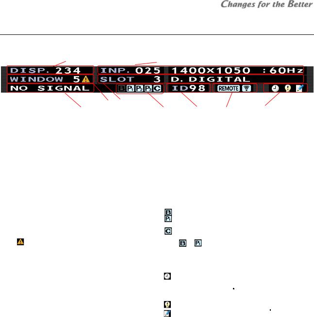
For remote control, the monitors have 2 operation modes: “normal mode” and “advanced mode”. The normal mode is for usual operation and advanced mode for set-up and adjustment. [NORMAL] button switches the modes when there is no adjustment menu on screen. This status bar is shown on screen in the advanced mode.
1 |
2 |
|
3 |
4 |
|
|
|
Normal mode |
5 |
6 |
7 |
8 |
9 |
|
|
|
|
|
|
Following operations are available in normal mode. |
|
|
|
||
Button |
Function |
|
|
|
|
[POWER] |
Switch between power-on and standby state |
|
|
|
|
[DISPLAY] |
Status information, switch the contents on the status indicator |
|
|
|
|
[ESC] |
Status information off |
|
|
|
|
[NORMAL] |
Switch between normal and advanced mode |
|
|
|
|
Numbers |
Recall a display memory (page 63) by 3-digit number. Press 001 for display memory 1. |
|
|||
Advanced mode
Monitor adjustments such as color balance and input signal adjustments should be done in advanced mode.
Status bar
|
No. |
|
Description |
No. |
|
Description |
|
|
|
|
|
||
1 |
|
Selected display memory number (page 59) |
|
|
Redundancy (page 51) and color-key (page 50) setting, status |
||||||||
|
|
|
• |
: BOARD REDUNDANCY mode |
|||||||||
|
|
|
|
|
|
||||||||
|
|
|
|
|
|
• |
: PORT REDUNDANCY mode (The number shows the slot |
||||||
|
|
|
Input memory number (page 54) and its comment on the |
|
|
||||||||
2 |
|
6 |
|
|
number) |
|
|
|
|
|
|||
|
|
|
foreground window |
|
|
• |
: COLOR-KEY mode |
||||||
|
|
|
Foreground window number |
|
|
||||||||
3 |
|
|
|
These indicators are shown when the function is set ON. The color of |
|||||||||
|
icon is shown when the window is displayed in space |
|
|
indicator |
or |
changes to yellow when the signal is switched. |
|||||||
|
|
|
coordinates on another monitor. |
7 |
|
Unit ID number |
|
|
|
|
|
||
4 |
|
Slot number and input port on foreground window |
8 |
|
Remote ID indicator |
|
|
|
|
|
|||
|
|
* It is shown when remote controlling is available by remote ID setting. |
|||||||||||
|
|
|
|
|
|
||||||||
|
|
|
Image status |
|
|
Monitor status |
|
|
|
|
|
||
|
|
|
• Test pattern name: in internal test pattern displaying |
|
|
• |
: In waiting time for lamp calibration (page 52) or for initial sensor |
||||||
|
|
|
• SCREEN MUTE: in screen mute |
|
|
||||||||
|
|
|
|
|
|
data obtaining (page 47) ( |
Lamp |
). |
|
|
|||
|
|
|
• WINDOW MUTE: One of the windows is mute. |
|
|
|
|
|
|||||
|
|
|
|
|
|
The |
operation |
will be completed in 5 minutes and then the |
|||||
|
|
|
• NO SIGNAL: no signal on the foreground window |
|
|
|
|||||||
5 |
|
9 |
|
|
indication will disappear. |
||||||||
|
|
|
|
||||||||||
|
|
|
|
|
|
• |
: The spare lamp status is not “NEW” ( |
Changer |
). |
||||
|
|
|
|
|
|
• |
: Adjustment values have been changed. |
||||||
|
|
|
|
|
|
|
* It appears when a value is changed automatically by internal |
||||||
|
|
|
|
|
|
|
process as well as changed by remote control. |
||||||
operation Basic
Remote ID
An individual monitor can be controlled remotely. Specify it with [FUNC] button followed by 2-digit unit ID number. Specifying 00 means that all monitors will be controlled. To control only ID 1 monitor, press [FUNC] + [0] + [1].
•Arrow keys after [FUNC] can also specify the ID. Left/right buttons change the ID by 1 and up/down buttons by 10. Press [ENTER] button to confirm.
•Remote ID switch is available even when the menus are on displayed on the screen.
Test patterns
[TEST] button shows internal test patterns. Every press cycles through the patterns in the following order. Full-bit white -> Crosshatch -> Adjustment white -> Gradation -> Color bar -> Test pattern off -> (Full-bit white)
REV 1.3 9

operation Basic
1.3.3 Menus
Basic menu operations
•The up/down arrow buttons on the remote control move the yellow cursor to select menus.
•The left/right arrow buttons change the value in a menu with left/right triangle marks.
•In a menu with “>” mark on the right, [ENTER] button shows its lower layer menu. [ESC] button restores the original upper menu.
•In a menu with an enter mark on the right, [ENTER] button confirms or executes the menu.
•When values are changed in a menu,  mark appears. Save the change according to the necessity.
-In WINDOW PRIORITY menu, the mark appears when an input memory in any of the windows is changed.
-In INPUT MEMORY menu, the mark appears when an input memory in the top window is changed.
•In the menu displaying, [MENU1] button changes the menu GUI to the simple one. The image area behind the menu can be observed widely. Re-pressing the same button restores the original menu.
TOP menu
The TOP menu is displayed by [MENU1] button on the remote control in the advanced mode. Starting from the menu, which is the top of the menu tree, lower menus can be choosen.
•Allocated short-cut buttons directly access each menu not-through the TOP menu.
INFORMATION menu
It shows various status information on screen. Short-cut: [DISPLAY] button
1 and 2 in SIGNAL column represent with or without signals on each input port (The signal from the SDI input board is shown only in 1). In the case of the daisy chain board, it shows following signals.
1: digital in, 2: analog in, 3: video in, D: digital out
Lamp
LED
LCD
•Menus are not displayed when the monitors are controlled by Wallaby.
10 Seventy Series Set-up Manual
ADVANCED INFORMATION menu
Pressing-and-holding [DISPLAY] button on the status information displays the advanced information. The NUMBER section shows temperetures and fan status in the following positions.
Lamp
Power PCB 1 Power PCB 2 DLPTM chip Lamp A Lamp B
LED
|
|
No. |
1 |
|
2 |
|
3 |
|
4 |
|
|||||
|
|
Temp. |
|
Power PCB 1 |
Power PCB 2 |
|
DLPTM |
|
|
|
|||||
|
|
/ fan |
|
|
chip |
|
|
|
|||||||
|
|
|
|
|
|
|
|
|
|
|
|
||||
|
|
No. |
|
|
5 |
|
|
6 |
|
|
7 |
|
|
8 |
|
|
|
|
|
|
|
|
|
|
|
|
|||||
|
|
Temp. |
|
Red LED |
Green LED |
|
Blue LED |
|
|
|
|||||
|
|
Fan |
|
|
Green LED 1 |
|
|
Green LED 2 |
|||||||
|
|
|
|
|
|
|
|
|
|
||||||
LCD
No. |
1 |
2 |
3 |
Temp. |
Power PCB 1 |
Power PCB 2 |
Sensor PCB |
Fan |
Fan 2 (left) * |
Fan 2 (right) * |
|
* Seen from the panel front
SENSOR DATA menu |
LCD |
|
Basic |
|
Pressing [VIDEO] + [DISPLAY] button in the advanced |
||||
|
||||
mode shows the light sensor data. |
operation |
|||
|
|
|
||
INPUT SELECT menu
It can select input ports to be adjusted (page 54). Selected input signal will be displayed on top. Short-cut: [INPUT A] button
WINDOW PRIORITY menu
It can set the window overlay priority order. The designated window will be displayed on top or last behind other windows.
Short-cut: Press-and-hold [INPUT A] button
It shows the priority order list and can set the order all together, unlike PRIORITY menu (page 62) in display memory which should enter in each window menu to set. To save the order, enter DISPLAY MEMORY menu and save in a display memory (page 63).
The  mark appears when an input memory in the window is changed. To save the change, move the window priority to the top and save the input memory.
REV 1.3 11
panel Control
MEMORY CALL menu
Registered input memories / display memories can be called (page 58, 63).
Short-cut: [MEM LIST] button
INPUT MEMORY menu
It can set input signals. See on page 54 for detail. The setting can be memorized in 128 input memories. Short-cut: [INPUT B] button
DISPLAY MEMORY menu
It can set display layout patterns. See on page 59 for detail. The setting can be memorized in 256 display memories.
Short-cut: [MENU2] button
SYSTEM SETTING menu
It can set an entire monitor / screen condition. See on page 36 and 48 for detail. One condition is memorized in the monitor.
Short-cut: Press-and-hold [MENU2] button.
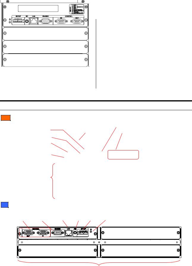
1.4 Control panel
The control panel has the following functions.
Cube
Network port (page 32)
Wired remote port (page 8)
Dipswitches
(page 32)
Standby switch (page 33)
Input board slots (page 15)
|
RS-232 port (page 32) |
Status indicator” |
Control ports (page 32) |
(page 66) |
Slot 1
Slot 2
Slot 3
LCD
Control |
RS-232 |
Network |
Wired remote |
Dipswitches |
Standby |
|
ports |
port |
port |
port |
(page |
32) |
switch |
(page 32) |
(page 32) |
(page 32) |
(page 8) |
|
|
(page 33) |
|
|
|
|
|
|
Slot 1 |
|
Slot 3 |
|
|
|
|
Slot 2 |
|
|
|
Input |
board |
slots |
(page 24) |
12 Seventy Series Set-up Manual

2 Cube installation (Cube)
2.1 Safety precaution
 This product requires special installation to prevent falling or toppling. This should be done by installation specialists.
 Be sure to read this manual and the user’s manual for your safety before starting assembly or installation.
 Be sure to use supplied accessories for assembly or installation.
 Attach all the screws and fixtures specified in this manual securely.
 Reinforce the wall surface and floor so that it can support the total weights of the products permanently and resist earthquakes, possible vibrations, and external forces.
 Ensure that the safety factor is more than 10 (or ensure that the total bolts can bear ten times the weight of products and the brackets).
 Inspect the mounting fixings more than once in a year as needed.
 Do not use the product near a heater or in a humid, dusty or smoky location.
 Do not install the product with its intakes, exhaust slots and ventilation holes blocked. The unit may overheat and cause a fire or breakdown.
Rear |
Front |
 Be careful not to pinch your fingers while sliding the screen holding arms (Front).
 Be sure that a lighting or sunlight does not leak into the screens.
 Be sure to mount/demount the screen by 2 or more people. These works may be perilous particularly on a height or a narrow scaffold.
Handling instructions for 80” screen
Because 80” screens are large and heavy, the screens should be held carefully.
•To prevent the screen from damage or breakage, carry the screen by two or more people.
•Hold the short sides of the screen frame or the corners when picking up the screen. Holding the center of the long sides of the frame (between labels) may damage the screen edge due to its heavy weight.
•Do not lay the screen with face up on the floor or table. The screen frames may not support the heavy and large screen surface.
REV 1.3 13
precaution Safety

Preparation
LED Safety LED
The LED engines are CLASS 2 LED products.
An exposure hazard may exist only if the protective housing is removed.
 Do not look into the LED light directly.
 Do not lens the LED light at anyone.
 Looking at the LED light directly may damage eyesight.
 Use of controls, adjustments or performance of procedures other than those specified herein may result in hazardous radiation exposure.
• Specification of the LEDs
|
LED |
|
|
Wave length |
|
|
Pulse width |
|
|
Maximum |
|
|
|
|
|
|
|
|
illumination power |
|
|||
|
|
|
|
|
|
|
|
|
|
|
|
|
Red |
623 nm |
|
234 μs |
|
41.24 mW |
|||||
|
Green |
525 nm |
349 μs |
26.43 mW |
|||||||
|
Blue |
462 nm |
218.3 μs |
|
34.76 mW |
||||||
•The LED light irradiation window is the projection lens on the upper-center of the engine products.
2.2 Preparation
2.2.1 Accessories
•Remove desiccant taped on the products. (no desiccant in engine integrated cubes)
•Remove a shipping protection sheet tucked in the lamp replacement door (page 65).
• Make sure that all of the following items are supplied. |
• Prepare following tools. |
Supplied accessories |
Q’ty per unit |
|||
Hex socket head bolts (M6) |
8 |
(12 for 80”) |
||
Flat washers (for M6) |
8 |
(12 for 80”) |
||
Spring washers (for M6) |
8 |
(12 for 80”) |
||
Seals for Joint holes |
1 |
|
||
Control cable |
1 |
|
||
User’s manual |
1 |
|
||
|
|
|
|
|
Cable ties ( |
Front |
) |
6 |
(50”), 10 (60”, 67”) |
Necessary tools
Hex keys 2mm, 2.5mm, 3mm, 4mm, 5mm
Phillips screwdrivers #0, #2
Level
Stepladder
Spacers (for screen gaps)
Wrenches (for base stands)
2.2.2 Input boards installation
Install input boards into the slots according to input signal configurations.
•Be sure to turn off the main power switch before installation.
•In Front, open the screen unit (page 20). The input
board slots are located inside the cubes.
1Unscrew the 2 screws on the slots evenly with a hex key (2.5mm) to remove the cover panels.
Screws
Cover panels
Input board slots
2 Insert input boards into the slots along their guide rails.
3 Firmly fix the boards until the end by evenly and alternately tightening the screws on both sides removed in the step 1 (suggested torque: 0.7Nm). For uninstalling the boards, reverse the procedure.
14 Seventy Series Set-up Manual

2.2.3 Front attachment in 80” cabinet
This work is normally unnecessary.
When you pass the cubes through a narrow gate or door, you can shorten the depth of the 80” cabinet by separating the front attachment.
1 Remove the nylon washer with “C” shape on each screen fixing bolt.
Screen fixing |
|
bolt |
|
Nylon |
|
washer |
Front |
|
|
|
attachment |
2 Pull out the 4 screen fixing bolts from rear. Be sure not to drop the washers attached to the tip of the bolts.
Washer
3 Unscrew 4 hexagon socket head bolts (5mm) to detach the front attachment.
Front attachment
Hexagon socket head bolt
4 After passing through, reverse the procedure to restore.
•Inside the front attachment, there are 4 connecting plates which can be used as additional cube connecting holes when making a curved display wall. Prepare proper bolts, nuts and washers to connect the cubes together through these holes. Unlike other connecting plates on the main cabinet (page 19), there is no castle nut inside the attachment.
Connecting plate
Preparation
REV 1.3 15
embedding Engine
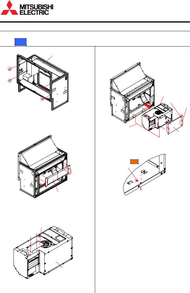
2.3 Engine embedding
Embed the engine units before cube installation (page 18) for separately supplied units.
2.3.1 Rear
1 Remove 4 bolt caps from the cabinet.
Cabinet
Bolt caps
2Loosen screws on the bottom edges of the rear panel and lift the panel to remove.
•Three screws on the top edge are hooks and need not to be loosened.
Rear panel
3 Attach a chassis cover, which is supplied with the cabinet, on the top panel of the engine unit with 2 screws.
4Remove the rear panel of the engine unit.
Loosen 2 screws on the top edge, release 4 latches and lift the panel to remove.
Engine unit
2 screws
4 latches
2 hex socket bolts
Rear panel
5Insert the engine unit into the cabinet fully and fix it with supplied 2 hex socket head bolts on both sides.
Holes for Front |
(not in use) |
2 hex socket bolts |
(on left and right sides) |
Bottom of engine unit |
6Put back the rear panels on both the engine unit and the cabinet.
Chassis cover
Engine unit
16 Seventy Series Set-up Manual

2.3.2 Front
1Loosen screws on the rear panel and lift the panel to remove. There is no need to unscrew them.
For 50”: Loosen 2 “A” screws and unscrew 7 “B” screws. There is no need to unscrew “A” screws.

 A
A
B
B
B
B
A
B
B B
2Remove the rear panel of the engine unit.
Loosen 2 screws on the top edge, release 4 latches and lift the panel to remove.
2 screws
4 latches
Engine unit
Rear panel
2 hex socket bolts

3Insert the engine unit into the cabinet fully and fix 2 metal brackets, which are supplied with the cabinet, with 2 screws each.
Bracket shape for 50"
2 brackets
4Fix the engine with supplied 2 hex socket head bolts on both sides.
Holes for Rear
(not in use)
2 hex socket bolts
Bottom of engine unit
5Put back the rear panels of both the engine unit and the cabinet.
•The engine unit can be embedded from the screen side as well.
1In the same manner as above step 3, fix the 2 metal brackets from the rear side.
2Put the engine unit in the cabinet from the front side. Be careful not to touch the mirror.
3 Fix the bottom of the engine unit on the cabinet in the same manner as above step 4.
4 Put back the rear panel of the engine unit.
REV 1.3 17
embedding Engine

stacking Cube
2.4 Cube stacking
2.4.1 Screen demounting
Rear:
Loosen screen fixing bolts to demount the screen (in screen integrated models).
Screen unit
Fixing
bolts
Front:
Unlocking
Release delivery locking before screen demounting / mounting.
•Screen-holding arms (in screen separated models) Peel off tapes from the screen-holding arms.
Screen-holding arm
Tape
Tape
•Shipping lock bolts (in screen integrated models) remove 2 shipping lock bolts (M5-45mm, white hex socket bolts).
Shipping lock bolts
Demounting
1Pull up the screen handles on both sides to draw the screen unit till locked and put the handles back to the original positions.
Screen-drawing handles
(1)
(2) 
2 While pressing the release buttons on both sides to the end, lift up the screen unit till it surely touches the guides on both sides. Open the lower part of the screen (about 15°) to pull it down on the skew.
Guide (on both sides)
(2) |
(1) |
Release button |
(on both sides) |
(4) |
(3) |
3Put back the screen-holding arms into the cabinet by pressing down the slide lock lever (only on the right side).
(2)
(1)
Slide lock lever |
Screen-holding arm |
18 Seventy Series Set-up Manual
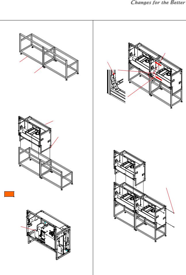
2.4.2 Base stands and cubes assembling
1Make base stands both level and plumb by means of a level.
Base stands
Adjusters
2 Place a cube in the bottom row on the base stand.
3 Fix the cube at 4 points (8 points for 80”) with supplied hex socket head bolts, spring washers and flat washers.
•Tighten the bolts with appropriate force (suggested torque: 3.9Nm).
Cube
Hex socket bolts
Spring washers
Flat washers
Front:
To access the rear fixing points, open the duct covers on both sides by pulling the latch.
Latch
Duct covers 
4Place a next bottom row cube on the base stand and fix it in the same way.
5 Connect these cubes together at 4 points with supplied hex socket head bolts, spring washers and flat washers.
Hex socket bolts Spring washers Flat washers
Connecting plate
•When making a curved display wall and you have to remove the connecting plates, put substitute
washers with equivalent strength on the holes.
6 Place other cubes for the upper row on the row of cubes.
7 Connect these cubes vertically and horizontally in the same manner as step 3 and 5.
Seals for Joint holes
•To prevent cubes from falling, make sure the cubes are stably assembled by checking that they are
level.
8 After all cubes are joined together, stop up unused holes on both sides of the cubes with supplied seals for joint holes.
REV 1.3 19
stacking Cube

stacking Cube
2.4.3 Screen mounting and open/close (Front)
Screen mounting
1 Draw the screen-holding arms from the cabinet till locked while pressing down the slide lock lever (only on the right side).
(2)
(1)
Screen-holding arm
Slide lock lever
2Mount a screen unit onto the cabinet.
Lift up the screen unit on a skew (about 15°) till the part B surely touches the part A (guides) on both sides. Make the screen upright rounding on the part A to hang it on the arms.
BA
(3)
(2)
(1)
3Push the screen unit along the rails till the end while pressing down the slide lock lever (only on the right side).
(1)
(2)
Slide lock lever
Screen opening
 About one-meter space is needed in front of the screens for the opening. Prior to work, make sure that there is no object such as steps in the working space.
 Open/close the screen units one-by-one in a display wall with making sure if adjacent screens are surely shut so as not to shift the center of gravity too much.
  To prevent cubes from toppling during screen open/close, use the support base contained in the cube carton boxes when the cubes are not fixed to a base stand or other cubes.
Support base
 Be careful not to trap your fingers during the work.
1Pull up the screen handles on both sides to draw the screen unit till locked and put the handles back to the original positions.
Screen-drawing handles
(1)
(2)
2Press down the open switch on the left at first which will be locked. While pressing down the other open switch on the right, pull up the lower part of the
screen to open.
Open switch |
(1) |
(left) |
|
(3) |
(2) |
Open switch |
(right) |
20 Seventy Series Set-up Manual
Screen closing
 Be careful not to trap your fingers during the work.
1 Push down the lower part of the screen lightly till locked.
2Push the screen unit along the rails till the end while pressing down the slide lock lever (only on the right side).
(1)
(2)
Slide lock lever
•The screen unit may touch adjacent screens depending on the screen gap adjustment. Adjust the gaps appropriately.
2.4.4 Screen gaps adjustment
Rear:
1 Lightly fix a screen unit on the cabinet with 4 screen-fixing screws.
Screen unit
Fixing screws
2Adjust the screen gaps with spacers to be as follows: 50”: 1mm / 60”: 1.5mm / 67”: 2mm / 80”: 3mm
 Screen gap
Screen gap
3 Tighten the 4 screen-fixing screws with appropriate force (suggested torque: 3.9Nm).
Front:
1 Open the screen unit.
2Loosen 5 fixing screws for screen adjustment with a hex key (3mm) (fixing screws: 1 for horizontal, 2 for vertical on each side).
H.fixing screw
2 V. fixing screws (on both sides)
3Optional motor unit (S-MA70E) allows you to adjust the screen gaps by remote control. Connect the motor unit to the cube in reference to “Mirror correction (page 41).
Motor units
L R
Drive unit 


PR
stacking Cube
REV 1.3 21
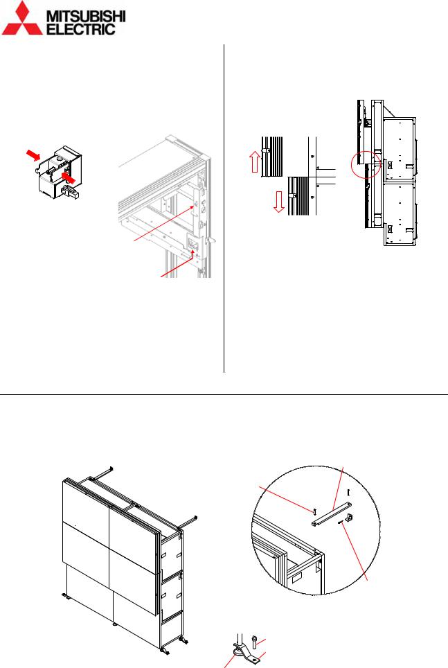
stacking Cube
4 Snap the motor units in the screen adjustment screws.
•The motor unit of PL is not used for the gap adjustment.
Screw |
Motor unit |
Menu |
Vertical (left) |
L |
SCREEN-L |
Vertical (right) |
R |
SCREEN-R |
Horizontal |
PR |
SCREEN-H |
H adjusting screw
V. adjusting screws (on both sides)
5 Display SYSTEM SETTING > MAINTENANCE > MECH ALIGNMENT menu.
6 Shift the screen position from side to side and up and down so that the screen gaps will be as follows: 50”: 2mm / 60”: 2.5mm / 67”: 3mm
•The screen is rotated by different travel distance on both vertical adjustment screws.
7 After the adjustment, tighten the 5 fixing screws which have been loosened in the step 2.
•The screen unit may touch adjacent screens depending on the gap adjustment. Adjust the gaps appropriately.
Manual adjustment
The gaps can be adjusted manually as well. Turn the adjustment screws with a hex key (4mm) instead of the motor units. One turn of the screws shifts the screen approximately 0.8mm.
Close the screen unit to check the gap and repeat the steps until being appropriate. Tighten the 5 fixing screws after the adjustment.
2.4.5 Fixing to the wall and floor
1 Firmly fix the base stands onto the floor by means of fixing brackets and/or anchor bolts. 2 Fix the upper back part of the cubes to the wall behind by means of fixing brackets.
 To prevent the cubes from falling due to unpredictable events such as earthquakes or shocks, fix them firmly to the wall and floor. Furthermore, carefully confirm the strength of the fixing areas (wall and floor) of the installation room. The fixing method differs depending on the number of cubes.
Wall-fixing brackets
Bolts
Bolts
Anchors
Floor-fixing brackets
Adjusters
After the completion, proceed to “Adjustment” (page 32).
22 Seventy Series Set-up Manual

3 LCD panel installation (LCD)
3.1 Safety precaution
 This product requires special installation to prevent falling or toppling. This should be done by installation specialists.
 Be sure to read this manual and the user’s manual for your safety before starting assembly or installation.
 Be sure to use supplied accessories for assembly or installation.
 Attach all the screws and fixtures specified in this manual securely.
 Do not dissolve or revamp the product except the areas which are specified in this manual.
 Do not install this product on an inclined place or unstable place. The product may drop or fall over which may cause injury.
 Do not install this product on its side, upside down, on its rear, face down, or in a slanting position.
 Do not use the product under the following circumstances, which may cause fire or electric shock.
•in a dusty or humid place
•a place where airstream from something like air conditioning directly blows to an exhaust vent in the product.
•in a oily, smoky or damp place
•near a heater
•in a vibratory area
 Do not use this product outdoors.
 Inspect the mounting fixings more than once in a year as needed.
 Do not install the product with its intakes, exhaust slots and ventilation holes blocked. The unit may overheat and cause a fire or breakdown.
 Be sure to mount/demount the screen by 2 or more people. These works may be perilous particularly on a height or a narrow scaffold.
 Unplug immediately if there is something wrong with your product.
How to handle the LCD panels
 Do not touch the top surface or left-hand surface as viewed from the front surface of the product. Doing so may cause failure.
 When carrying the product, make sure to have two people carry it while holding onto the handles. In addition, being careful not to tough the panel screen, cautiously support the bottom surface of the panel.
 Be careful not to twist or bend the product.
 Be careful not to bump or apply pressure on the panel.
 When laying the product flat, be sure to place the panel on a flat surface with a something soft like a blanket underneath, and be careful not to scratch the surface of the panel or allow the panel to be subjected to excessive pressure. Also do not leave the panel face-down for a long while.
 Protect the panel from static electricity.
To keep static buildup to a minimum, remove the protective sheet on the panel surface slowly.
 The surface of the panel is rather fragile and can be damaged easily. Do not push down hard on it or scratch it.
 Immediately wipe away any drops of water or oil that adhere to the panel. Allowing water or oil to remain on the panel for long periods of time may result in the panel becoming stained or changing color.
REV 1.3 23
precaution Safety

Preparation
3.2 Preparation
3.2.1 Accessories
Make sure that all of the following items are supplied.
Supplied accessories |
Q’ty per unit |
Control cable |
1 |
User’s manual |
1 |
Cable ties |
5 |
3.2.2 Input boards installation
Install input boards into the slots according to input signal configurations
• Be sure to turn off the main power switch before installation.
1 |
Place the panel on a flat surface with a |
|||
|
something soft like a mattress or blanket |
|||
|
underneath. |
|
|
|
|
• Do not leave the panel face-down for a |
|||
|
long while. |
|
|
Slot 3 |
2 |
Unscrew the 2 screws on the slots evenly |
|||
|
with a hex key (2.5mm) to remove the |
|||
|
cover panels. |
|
|
|
3 |
Insert input boards into the slots along |
|||
|
their guide rails. |
|
|
|
4 |
Firmly fix the boards until the end by |
|||
|
evenly and alternately tightening the |
|||
|
screws on both sides removed in the step 1 |
|||
|
(suggested |
torque: |
0.7Nm). |
For |
uninstalling the boards, reverse the procedure.
Cover panel
Slot 1
Slot 2
Screws
3.3 Mounting
3.3.1 For using commercial wall mount brackets
The product is equipped with screw holes on its back side to be fixed with a commercially available wall mount brackets. You can use a bracket which is compliant with VESA300.
Caution for installation
Mechanical structure
 Be sure to read “safety precaution” in this manual (page 23) and follow the instruction.
 Be sure to read the bracket’s instruction manual and installation procedure as well as this manual.
 Use a bracket which can bear 4 times or more weight of the product. When the strength is unsure, put a 90kg weight on the product and check if it is held stably for 1 minute.
 Before mounting, check the strength of the wall. Mount on a wall which safety factor is more than 10 (or ensure that it can bear ten times the weight of products and the brackets). When it is not sufficient, reinforce the wall surface. (The weight of VS-L46XM70U: about 30kg)
 Carefully install onto the wall not to get loose due to vibration etc. Wrong installation or installation with insufficient strength causes the product to fall resulting in a serious accident or injury.
 The weights shall be borne by a sturdy structural material such as a joist. Secure the bracket using bolts, spring washers, washers, and nuts.
 Don’t install the bracket directly on a wall having insufficient strength, or don’t install it using wooden screws or anchor screws. Also don’t install it on wooden structural materials or blocks.
 Ensure that the safety factor per bolt is more than 10 (or ensure that the total bolts bear the weight ten times the sum of the weights of the products and the brackets).
 Install the products not to touch with adjacent panels. The outer circumference of the panels is quite weak and hard pressure or impact may cause damage.
 For future maintenance, it is recommended that the product be installed so that it can be taken out of the bracket easily.
24 Seventy Series Set-up Manual

Ventilation
 Refer to “Image persistence” (page 70) for ventilation concept.
 Don’t block the ventilation holes. The temperature inside the product rises high causing a fire or breakdown.
Exhaust
Intake
Intake
 To ensure a proper airflow for cooling, create a space around the products at least as shown below (unit: mm).
Panel
Panel
 Exhaust hot air gets stacked above the product. Design the structure so as to release it and flow enough fresh air in from the bottom as shown below.
Exhaust
 In high configurations, the temperature condition gets worse in the upper panels. The recommended stack number is up to 6. When over that configuration, it requires an additional ventilation way to enhance the efficiency.
 Operate under the range of 5 to 30 centigrade conditions when the panels are used in BRIGHT mode (page 48).
Mount holes for brackets
You can use a bracket which is compliant with VESA300. Utilizing 8 screw holes (M6, 10mm depth) on the back of the product, mount it on a bracket.
8 screws
•At least use 4 screw holes to mount as shown below. To prevent from drop-off, it is recommended to use rest of holes as well.
4 points outside
Or 4 points inside
•Use appropriate screws with 10mm or less. Otherwise, it may be imperfect fixing or it may damage the nuts inside the products.
Proceed to “IR receiver attaching” (page 31).
Mounting
Intake
REV 1.3 25

Mounting
3.3.2 For using optional wall mount frame (BR-XM70KK)
Caution for installation
Mechanical structure
 Be sure to read “safety precaution” in this manual (page 23) and follow the instruction.
 Before mounting, check the strength of the wall. Mount on a wall which safety factor is more than 10 (or ensure that it can bear ten times the weight of products and the wall mount frames). When it is not sufficient, reinforce the wall surface. (The weight of VS-L46XM70U: about 30kg, BR-XM70KK: about 25kg)
 Carefully install onto the wall not to get loose due to vibration etc. Wrong installation or installation with insufficient strength causes the product to fall resulting in a serious accident or injury.
 The weights shall be borne by a sturdy structural material such as a joist. Secure the wall mount frame using bolts, spring washers, washers, and nuts.
 Don’t install the wall mount frame directly on a wall having insufficient strength, or don’t install it using wooden screws or anchor screws. Also don’t install it on wooden structural materials or blocks.
 Ensure that the safety factor per bolt is more than 10 (or ensure that the total bolts bear the weight ten times the sum of the weights of the products and the wall mount frame).
 Before installation, calculate cable length for external connection and prepare them. Inappropriate length may make the wiring difficult.
Ventilation
 Refer to “Image persistence” (page 70) for ventilation concept.
 To ensure a proper airflow for cooling, create a space around the products at least as shown in the right top figure (unit: mm). Also block 2 exhaust vents on each frame of the top row and one intake vent per frame on the bottom row.
Blocked 2 exhaust vents (only on the top row)
Panel
Panel
Blocked intake vent (only on the bottom row)
 Prepare the covers by yourself in reference to the figures below (unit: mm). They can be fixed with 4 screws (M4, 10mm or more length) through holes on the wall mount frame (suggested torque: 0.7Nm). Do not block other vents.
Material (example): aluminum or steel plate with 1mm thickness
• Top cover
• Bottom cover
• Side cover (if you cover unused cabling holes on both sides of the display wall)
26 Seventy Series Set-up Manual
Loading...