


2002
Service
 MITSUBISHIELECTRIC Manual
PROJECTION TELEVISION VK20 CHASSIS
WT-42311
WT-A42
CAUTION:
Before servicing this chassis, it is important that the service person read the "SAFETY PRECAUTIONS" and "PRODUCT SAFETY NOTICE" contained in this manual.
SPECIFICATIONS
• Power |
: AC 120V, 60Hz |
• Speaker |
: Two 5" round, full range (8Ω 5W) |
|
|
240W |
|
|
|
• Frequency |
: VHF |
54 ~ 470MHz |
• Input Level |
: VIDEO IN JACK (RCA Type) |
|
1.0Vp-p 75Ω unbalanced |
|||
Range |
UHF |
470 ~ 806MHz |
|
|
|
|
|
|
: AUDIO IN JACK (RCA Type) |
• Antenna Input |
: VHF/UHF 75Ω unbalanced |
|
-4.7dBm 43kΩ unbalanced |
|
|
: S-VIDEO IN JACK (Y/C separate) |
|||
|
|
|
|
|
• CRT Size |
: [7 inches] |
|
Y=1.0 Vp-p C=0.286Vp-p(BURST) |
|
|
75Ω unbalanced |
|||
|
|
|
|
|
• High Voltage |
: 32.0kV (at 0A) |
|
: COMP / Y, Cr, Cb (RCA Type) |
|
|
Y=1.0 Vp-p. Cr, Cb=700mVp-p |
|||
|
|
|
|
|
|
|
|
|
: ATV / Y(G), Pr(R), Pb(B), H, V |
• Cabinet |
: 39"(W)x34"(H)x25"(D) |
|
Y 1.0Vp-p with sync 75Ω (RCA Type) |
|
|
Pr, Pb: 700mV 75Ω |
|||
Dimensions |
|
|
|
|
|
|
|
H, V: 3.0Vp-p 75Ω |
|
|
|
|
|
|
• Weight |
: 105 lbs |
• Output Level |
: VIDEO OUT JACK (RCA Type) |
|
|
|
|
||
1.0Vp-p 75Ω unbalanced
: AUDIO OUT JACK (RCA Type) -4.7dBm 4.7kΩ unbalanced
•Weight and dimensions shown are approximate.
•Design specifications are subject to change without notice.
MITSUBISHI DIGITAL ELECTRONICS AMERICA, INC.
9351 Jeronimo Road, Irvine, CA 92618-1904
Copyright © 2002 Mitsubishi Digital Electronics America, Inc.
All Rights Reserved

MODELS: WT-42311 / WT-A42
CONTENTS |
|
INTRODUCTION ................................................................................................................................ |
5 |
PRODUCT SAFETY NOTICE ............................................................................................................. |
5 |
SAFETY PRECAUTIONS ................................................................................................................... |
6 |
CABINET DISASSEMBLY |
|
Front View Disassembly ................................................................................................................. |
7 |
Rear View Disassembly .................................................................................................................. |
8 |
SERVICING THE LENTICULAR SCREEN AND FRESNEL LENS |
|
Lenticular Screen and Fresnel Lens Removal .................................................................................. |
9 |
Lenticular Screen and Fresnel Lens Installation .............................................................................. |
9 |
SERVICING PCBs |
|
Accessing the Main Chassis ........................................................................................................ |
10 |
PCB Locations .............................................................................................................................. |
11 |
Main Components Location........................................................................................................... |
11 |
CRT REPLACEMENT |
|
Second Anode Lead Removal ....................................................................................................... |
12 |
CRT Removal ................................................................................................................................ |
12 |
CRT Installation ............................................................................................................................ |
23 |
ELECTRICAL ADJUSTMENTS |
|
Test Equipment ............................................................................................................................. |
15 |
Initial Setup ................................................................................................................................... |
16 |
LED Indicator Diagnostics ............................................................................................................. |
17 |
Circuit Adjustment Mode ............................................................................................................... |
18 |
Convergence Adjustment Mode ..................................................................................................... |
19 |
Adjustment Items List ................................................................................................................... |
21 |
Adjustment Test Points ................................................................................................................. |
24 |
Adjustment Procedures |
|
High Voltage Regulation ....................................................................................................... |
25 |
Main/Sub Y Level ................................................................................................................. |
25 |
Main/Sub Color Level ........................................................................................................... |
26 |
CRT Cutoff ........................................................................................................................... |
26 |
White Balance (NTSC) ......................................................................................................... |
27 |
White Balance (HD) ............................................................................................................. |
27 |
Black Level .......................................................................................................................... |
28 |
Sub Contrast ....................................................................................................................... |
28 |
Dynamic Focus Preset ........................................................................................................ |
29 |
Lens Focus .......................................................................................................................... |
29 |
Electrostatic Focus .............................................................................................................. |
30 |
On Screen Display Character Position ................................................................................. |
30 |
Deflection/Convergence Geometry Presets .......................................................................... |
31 |
Deflection Circuit Geometry Adjustments ............................................................................. |
32 |
Convergence Circuit Geometry Adjustments ........................................................................ |
43 |
Centering and Static Convergence ....................................................................................... |
34 |
Coarse Convergence Adjustments ....................................................................................... |
35 |
Fine Convergence Adjustments ............................................................................................ |
36 |
CHIP PARTS REPLACEMENT ......................................................................................................... |
37 |
Page 3

MODELS: WT-42311 / WT-A42
REPLACEMENT PARTS |
|
Parts Ordering .............................................................................................................................. |
38 |
Critical and Warranty Parts Designation........................................................................................ |
38 |
Parts Tolerance Codes .................................................................................................................. |
38 |
Replacement Part Notes |
|
When replacing the RF-Switch or PCB-SIGNAL ................................................................... |
38 |
When replacing the EEPROM.............................................................................................. |
38 |
Quick Reference List .................................................................................................................... |
39 |
Service Parts List.......................................................................................................................... |
40 |
Screen Parts List .......................................................................................................................... |
51 |
CIRCUITRY BLOCK DIAGRAMS |
|
Power Supply ............................................................................................................................... |
52 |
Video / Color Signal Path .............................................................................................................. |
53 |
Sync Signal Path .......................................................................................................................... |
54 |
Deflection / HV .............................................................................................................................. |
55 |
X-Ray Protect ............................................................................................................................... |
56 |
HV Regulation ............................................................................................................................... |
57 |
Sound Signal Path ........................................................................................................................ |
58 |
Convergence ................................................................................................................................. |
59 |
Control Circuitry ............................................................................................................................ |
60 |
Section 2 .... Schematic Diagrams |
|
SCHEMATIC DIAGRAMS |
|
Overall Block Diagram ................................................................................................................... |
1 |
PCB-MAIN ..................................................................................................................................... |
2 |
PCB-POWER................................................................................................................................. |
3 |
PCB-TERMINAL (Input Sw) ............................................................................................................. |
4 |
PCB-TERMINAL (3DYC / Decoders) ............................................................................................... |
5 |
PCB-SIGNAL-1 (AV I.O) .................................................................................................................. |
6 |
PCB-SIGNAL-2 (Micro) ................................................................................................................... |
7 |
PCB-SIGNAL-3 (VCJ) ..................................................................................................................... |
8 |
PCB-SIGNAL-4 (Convergence Generator) ........................................................................................ |
9 |
PCBs - FRONT / CONTROL / CRT / PREAMP ............................................................................. |
10 |
PCB-DOUBLER-1 (Input) .............................................................................................................. |
11 |
PCB-DOUBLER-2) (Main) ............................................................................................................. |
12 |
PCB-DOUBLER-3 (Output) ........................................................................................................... |
13 |
PCB LAYOUT DIAGRAMS ............................................................................................................... |
14 |
Page 4

MODEL: WT-42311 / WT-A42
INTRODUCTION
This service manual provides service instructions for PTV Models WT-42311and WT-A42 using the VK20 chassis. Service personnel should read this manual thoroughly before servicing this chassis.
This service manual includes:
1.Assembly and disassembly instructions for the front and rear cabinet components.
2.Servicing of the Lenticular Screen and Fresnel Lens.
3.Servicing printed circuit boards (PCBs).
4.CRT replacement procedure.
5.Electrical adjustments.
6.Chip parts replacement procedures.
7.Circuit path diagrams.
The parts list section of this service manual includes:
1.Cabinet and screen parts.
2.Electrical parts.
Schematic and block diagrams of the above listed models are included in this service manual for better understanding of the circuitry. PCB drawings are also included for easy location of parts and test points.
PRODUCT SAFETY NOTICE
Many electrical and mechanical parts in television receivers have special safety related characteristics. These characteristics are often not evident from visual inspection nor can the protection afforded by them necessarily be obtained by using replacement components rated for higher voltage, wattage, etc.
Replacement parts which have special safety characteristics are identified in this service manual.
Electrical components having such features are identified by shading  on the schematic diagram and by bold type in the parts list of this service manual. The replacement for any safety part should be identical in value and characteristics.
Page 5

MODEL: WT-42311 / WT-A42
SAFETY PRECAUTIONS
NOTICE: Observe all cautions and safety related notes located inside the receiver cabinet and on the receiver chassis.
WARNING:
1.Operation of this receiver outside the cabinet or with the cover removed presents a shock hazard from the receiver's power supplies. Work on the receiver should not be attempted by anyone who is not thoroughly familiar with the precautions necessary when working on high voltage equipment.
2.Do not install, remove or handle the picture tubes in any manner unless shatterproof goggles are worn. People not so equipped should be kept away while the picture tube is being handled. Keep the picture tube away from the body while handling.
3.When service is required, observe the original lead dress. Extra precaution should be taken to assure correct lead dress in the high voltage area. Where a short-circuit has occurred, replace those components that indicate evidence of overheating.
X-Radiation warning
The surface of the cathode ray tubes (CRTs) may generate X-Radiation, so take proper precautions when servicing. It is recommended that a lead apron be used for shielding while handling the CRT. Use this method if possible.
When replacing the CRTs, use only the designated replacement part since it is a critical component with regard to X-Radiation. High voltage must be set as prescribed under the section titled Electrical Adjustments.
Leakage current check
Before returning the receiver to the customer, it is recommended that leakage current be measured according to the following methods.
1.Cold Check
With the alternating current (AC) plug removed from the AC source, place a jumper across the two AC plug prongs. Connect one lead of an ohm meter to the AC plug and touch the other lead to each exposed metal part (i.e. antennas, handle bracket, metal cabinet, screw heads, metal overlay, control shafts, etc.), particularly any exposed metal part that has a return path to the chassis. The resistance of the exposed metal parts having a return path to the chassis should be a minimum of 1Mega Ohm. Any resistance below this value indicates an abnormal condition and requires corrective action.
2.Hot Check ...Use the circuit shown below to perform the hot check test.
1.Keep switch S1 open and connect the receiver to the measuring circuit. Immediately after connection, and with the switching devices of the receiver in their operating positions, measure the leakage current for both positions of switch S2.
2.Close switch S1, energizing the receiver. Immediately after closing switch S1, and with the switching devices of the receiver in their operating positions, measure the leakage current for both positions of switch S2. Repeat the current measurements of items 1 and 2 after the receiver has reached thermal stabilization. The leakage current must not exceed 0.5 milliampere (mA).
Page 6
MODEL: WT-42311 / WT-A42
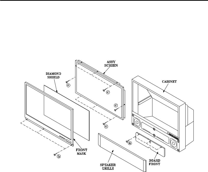
CABINET DISASSEMBLY (FRONT VIEW)
*Refer to PARTS LIST for Part Numbers
Front Cabinet Disassembly
1.Remove the Speaker Grille by pulling forward.
2.Remove the Board-Front by removing 3 screws "a".
3.Remove 3 screws “b” and then remove the Front Mask and Diamond Shield.
4.Remove 8 screws “c” and then the Assembly Screen.
Page 7

MODEL: WT-42311 / WT-A42
CABINET DISASSEMBLY (REAR VIEW)
Rear Cabinet Disassembly
1.Remove the Back Board by removing screws 7 "a".
2.Remove 6 screws "b" securing the Light Box Assembly.
3.Disconnect connector EJ.
4.Slide the Light Box Assembly out of the cabinet.
Page 8
MODEL: WT-42311 / WT-A42
SERVICING THE LENTICULAR SCREEN AND FRESNEL LENS
CAUTION: Wear gloves when handling the Lenticular Screen and Fresnel Lens.
This prevents cuts and finger prints. Do not place Fresnel Lens in the sun. This may cause fire and heat related injuries.
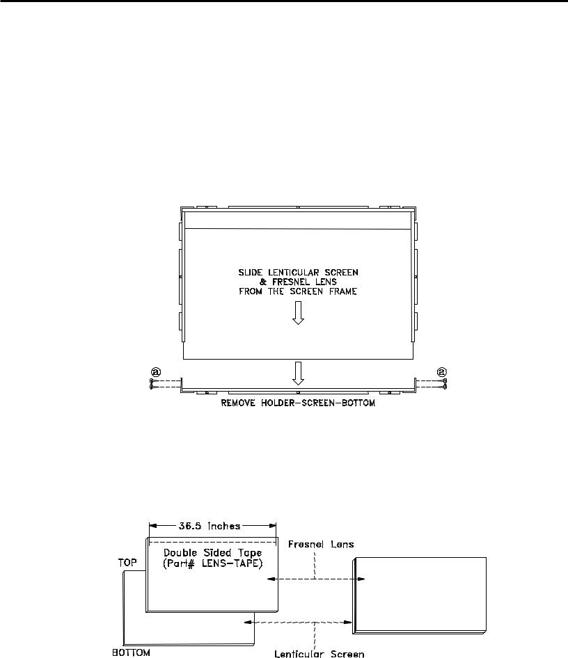
1.Lenticular Screen and Fresnel Lens Removal
1.Remove the screen assembly as shown in the Cabinet Front Disassembly procedure.
2.Remove screws “a” from the bottom Corner Brackets.
3.Remove the Holder-Screen-Bottom.
4.Slide the Lenticular Screen and Fresnel Lens from the Assembly Screen as shown below..
Note: When separating the Lenticular Screen from the Fresnel Lens, use caution while prying the Screen and Lens apart. Use a slot type screw drive, and remove the pressure sensitive double sided tape.
2. Installation of the Lenticular Screen and Fresnel Lens
Note: Store the Lenticular Screen and Fresnel Lens in a cool dry place. High humidity may deform the Lenticular Screen and Fresnel Lens.
1.Apply 36.5 inches of double sided tape (Part # LENS-TAPE) along the top front edge of the Fresnel Lens.
2.Place the Fresnel Lens on top of the Lenticular Screen and apply pressure at the top edge to bond them together as shown below.
3.Reverse the disassembly procedure to install the screens in the screen frame.
Page 9
MODEL: WT-42311 / WT-A42
SERVICING PCBs
Accessing The Main Chassis
In the VK20 chassis, the Main Chassis is located in front of the CRTs. Use the following procedure to access the Main Chassis.
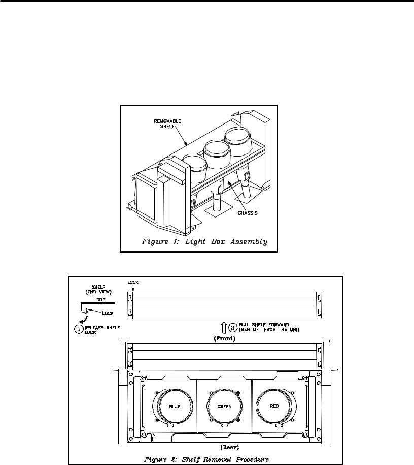
1)Remove the Light Box Assembly, refer to the Cabinet Rear Disassembly.
2)The shelf in the front of the Light Box Assembly is removable, refer to Figure 1.
3)Release the shelf lock. Apply pressure to the shelf lip on the right side (downward and towards the front). Refer to Figure 2
4)Hold both sides of the shelf, pull forward and then upward to remove the shelf.
Page 10

MODEL: WT-42311 / WT-A42
PCB Locations
Major Parts Locations
Page 11

MODEL: WT-42311 / WT-A42
ANODE LEAD REMOVAL
CAUTION: To prevent damage, the following procedure must be used when removing an Anode Lead from the Flyback Transformer.
1) Push the Anode Lead down.
2) While holding the lead down rotate the lead 90º counter clockwise.
3) Carefully remove the Anode Lead from the Flyback Transformer.
CRT REPLACEMENT
1. Removal of the CRT
Caution! High voltage should be completely discharged prior to CRT removal.
Since the CRTs receive high voltage from the Flyback transformer, discharge the CRTs by shorting the open end of the respective high voltage cable to chassis ground.
1.Refer to Cabinet Disassembly and remove the Light Box Assembly.
2.Remove the three Anode Lead Wires from the Flyback transformer and discharge the CRTs. (Use the above procedure)
3.Unplug the three PCB-CRTs.
4.Remove 4 screws "a" retaining the Optical Unit. [Figure 1]
5.Remove 4 screws "b" retaining the Lens of the respective CRT
6.Lift the Optical Unit from the Light Box and set it lens down on a flat surface.
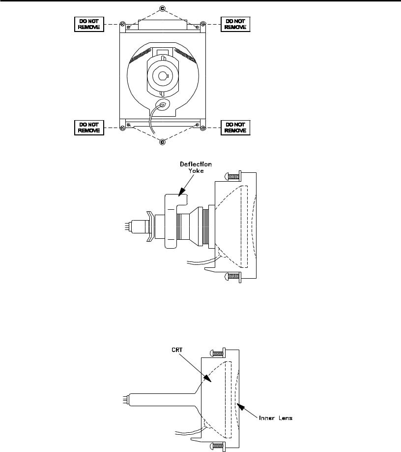
7.Remove 4 screws "c" retaining the CRT. [Figure 2]
Note: DO NOT loosen the spring loaded screws. Doing so will break the seal between the C-Element and the # 6 Lens, causing leakage of the CRT Coolant.
8. Remove the Deflection Yoke from the neck of the CRT. [Figure 3]
Figure 1
Page 12
MODEL: WT-42311 / WT-A42
Note: The 4 spring-loaded screws shown in Fig 2 and labeled as "DO NOT REMOVE", should not be loosened under any circumstance. Doing so will break the seal between the CRT and the CRT-Spacer, causing leakage of the CRT Coolant.
Figure 2
Figure 3
2. Installation of the CRT
Note: The replacement CRT is supplied as an assembly comprised of the CRT and the Inner Lens with the space between them filled with ethylene glycol. Care should be taken during handling and installation to prevent shock from disrupting the seal or alignment between the CRT and Inner Lens. [Figure 4]
Figure 4
Page 13
MODEL: WT-42311 / WT-A42
1.Carefully position the replacement CRT and fasten in place using 4 screws "c". [Figure 2]
2.Install the Deflection Yoke on the CRT neck. [Figure 3]
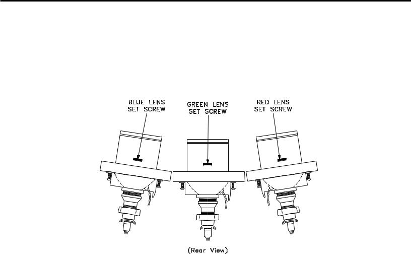
3.Install the Lens that was removed in step 5 of Removal of the CRT.
a)Position the Lens so that the Lens Adjustment Set Screw faces the rear of the TV [Figure 5].
b)Install the Lens mounting screws “b”. [Figure 1]
4.Insert the Optical Unit into the Light Box Assemblyand secure it with 4 screws “a” [Figure 1]..
5.Plug in the PCB-CRTs.
6.Insert the Anode Lead Wires into the Flyback Transformer.
7.Re-clamp the Lead Wire in its original position.
Figure 5
Adjustment procedures after replacing the CRT(s)
•CRT Cut Off / White Balance Adjustment
•Static Convergence Adjustment
•Dynamic Convergence Adjustment
Page 14

MODEL: WT-42311 / WT-A42
ELECTRICAL ADJUSTMENTS
Note: Perform only the adjustments required.
Do not attempt an alignment if proper equipment is not available.
1.Test Equipment
•Oscilloscope (Unless otherwise specified, use 10:1 probes)
•Signal Generator (both SD and HD capable)
•Frequency Counter
•Direct Current Voltmeter Direct Current Power Supply
•Multiplex Audio Signal Generator
•Direct Current Ampere Meter
2.Test Signal
A. Monoscope Signal
Note: If you do not have
a monoscope signal source, connect the unit to a VCR and play a Monoscope *alignment tape.
(* Part Number: 859C568060)
B.Color Bar Signal
Use the color bar signal shown below, unless otherwise specified in this manual.
Monoscope Signal
100%
75%
40%
40%
1H
Split-Field Color Bars (100% window)
Page 15

MODEL: WT-42311 / WT-A42
3.Initial Setup
A. Option Menu Setup
Follow the steps below for the initial set-up:
1.Select the "MENU" display by pressing the "MENU" button once.
2.Press the number buttons "2", "2", "7", "0" in sequence to select the "OPTION MENU" display.
3.Press the "ADJUST" button to select "INITIAL."
4.Press "ENTER."
NOTE: At this time channel 3 is automatically selected.
MENU-2-2-7-0
OPTION MENU
Initial |
|
Power Restore |
:OFF |
DTV Port |
:Auto |
Direct Key Mode |
:OFF |
B. Default Settings
MAIN MENU DEFAULT SETTINGS
SETUP |
|
|
Programs Not Rated |
Allow |
|
AUDIO/VIDEO |
|
Memorize channels |
ANT-A - Air |
|
Movie Rating |
PG |
|
A/V Memory Reset |
Ant-A |
Language (idioma) |
English |
|
V-CHIP LOCK By Time |
|
TV Speakers (Internal) |
On |
|
Front Button Lock |
Off |
|
V-Chip Start Time |
12:00AM |
|
Audio Output |
Variable |
CLOCK |
|
|
V-Chip Stop Time |
12:00AM |
|
AUDIO SETTINGS |
|
Clock Setting |
Auto |
|
Lock by Time |
Off |
|
TV Bass |
50% |
Time Zone |
Eastern |
|
Lock Time |
N/A |
|
TV Treble |
50% |
Daylight Savings Time |
Applies |
|
Unlock Time |
N/A |
|
TV Balance |
50% |
Clock Time |
N/A |
|
ADVANCED FEATURES |
|
TV Surround |
Off |
|
Set Day |
N/A |
|
Video Mute |
On |
|
TV Listen To |
Stereo |
CAPTIONS |
|
|
Black Enhancement |
On |
|
TV Level Sound |
Off |
Closed Captions |
On if Mute |
|
Auto Color Correction |
Onn |
|
VIDEO SETTINGS |
|
CC Background |
Gray |
|
TIMER |
|
|
TV Contrast |
1 |
CHANNEL EDIT |
|
Timer |
Off |
|
TV Brightness |
50% |
|
Antenna |
ANT-A |
|
Set Time |
12:00PM |
|
TV Sharpness |
50% |
Channel |
3 |
|
Set Day |
Everyday |
|
TV Color |
50% |
Memory |
Deleted |
|
Device |
Ant-A |
|
TV Tint |
50% |
Name |
N/A |
|
Channel |
3 |
|
TV Color Temp |
High |
SQV |
N/A |
|
COLOR BALANCE |
|
TV Video Noise |
Standard |
|
V-CHIP-LOCK |
|
Auto Color Correction |
Off |
|
TV Film Mode (Auto) |
Off |
|
V-Chip |
Off |
|
MANUAL COLOR ADJ (WT-42311) |
|
TV VSM Sharpness |
On |
|
TV Rating |
TV-PG |
|
Magenta |
50% |
|
TV Volume |
30% |
FVFantasy Violence |
Allow |
|
Red |
50% |
|
PIP Source |
Ant-A Ch 3 |
D-Sexual Dialog |
Allow |
|
Yellow |
50% |
|
PIP Position |
Lower Right |
L-Adult Language |
Allow |
|
Green |
50% |
|
POP Position |
Right Half |
S-Sexual Situations |
Allow |
|
Cyan |
50% |
|
Format |
Stretch |
V-Violence |
Allow |
|
Blue |
50% |
|
PIP/POP Format |
Side by Side |
Page 16

MODEL: WT-42311 / WT-A42
Items in the table below are set to following after Initalization.
AV Memory Initial Settings
A/V Memory |
Ant-A |
DTV |
NTSC |
COMP. |
|
Ant-B |
1/2/3 |
1/2 |
|||
|
|
||||
Contrast |
Max |
Max |
Max |
Max |
|
Brightness |
Mid |
Mid |
Mid |
Mid |
|
Sharpness |
Mid |
Mid |
Mid |
Mid |
|
Color |
Mid |
Mid |
Mid |
Mid |
|
Tint |
Mid |
Mid |
Mid |
Mid |
|
Color Temp. |
High |
High |
High |
High |
|
Video Noise |
Stnd. |
Stnd. |
Stnd. |
Stnd. |
|
Image type |
Video |
Video |
Video |
Video |
|
TV VSM |
On |
On |
On |
On |
|
Sharpness |
|||||
|
|
|
|
||
Bass |
Mid |
Mid |
Mid |
Mid |
|
Treble |
Mid |
Mid |
Mid |
Mid |
|
Balance |
Mid |
Mid |
Mid |
Mid |
|
Surround |
Off |
Off |
Off |
Off |
|
Listen To |
Stereo |
N/A |
N/A |
N/A |
|
Level Sound |
Off |
Off |
Off |
Off |
4. LED Indicator Diagnostics
The “Power ON LED” provides an indication of the sets operation, and the possible cause of a malfunction.
A.Initial Control Circuitry Check
Immediately after the TV is connected to an AC power source:
•The LED flashes three times ... indicating the Microprocessor has initialized and is functioning properly.
•If the LED does not flash ... the Microprocessor is NOT functioning.
B.Error Code Operational Check
Pressing the front panel “INPUT” and “MENU” buttons at the same time, and holding for 5 seconds, activates the Error Code Mode. The LED flashes denoting a two digit Error Code, or indicating no problem has occured since the last Initalization.
Note: The front panel buttons must be used, NOT those on the Remote Control.
•The number of flashes indicates the value of the MSD (tens digit) of the Error Code.
•The flashing then pauses for approximately 1/2 second.
•The LED then flashes indicating the value of the LSD (ones digit) of the Error Code.
•The Error Code is repeated a total of 5 times.
Example: If the Error Code is “24”, the LED will flash two times, pause, and then flash four times.
C.Error Codes
The Error Code designations indicating a malfunction, or no malfunction, are listed below:
Error Code |
Description |
12 |
No error has occurred. |
21 |
X-Ray Protect circuit. |
22 |
Short Protect circuit. |
23 |
Horizontal Deflection failure. |
24 |
Vertical Deflection failure. |
Page 17

MODEL: WT-42311 / WT-A42
5. Circuit Adjustment Mode
Except for the following, all adjustment items must be performed using the remote hand unit.
• Lens Focus |
FUNCTION |
CHASSIS |
|
• Electrostatic Focus |
|||
|
|
A.Activating the Circuit Adjustment Mode
1.Press the "MENU" button on a remote hand unit.
2.Press the number buttons "2", "2", "5", "7" in sequence. The screen will change to the Adjustment Mode.
Note: Repeat steps 1 and 2 if the circuit adjustment mode display does not appear on screen
|
|
Video Chr |
V20 |
|
|
|
MODE |
Mode 0 |
|
NTSC |
|
SIGNAL |
|
|
|
|||||
ITEM# |
|
1 |
SCT |
55 |
|
|
|
|
|
||||
|
|
|
|
|
|
|
|
|
ABBREV. |
|
DATA |
|
|
B.Selection of adjustment Functions and Adjustment Items
To select an adjustment item in the circuit adjustment mode, first select the adjustment function that includes the specific adjustment item to be selected. Then, select the adjustment item.
Refer to the following pages for the listing of adjustment functions and adjustment items.
1.Press the "AUDIO" button on a remote hand unit to select an adjustment function. Each time the button is pressed, the Function changes in the following sequence:
CABLE/DBS |
VCR |
DVD |
|
TV |
AUDIO |
1 |
2 |
3 |
POWER |
|
|||
4 |
5 |
6 |
|
7 |
8 |
9 |
|
|
|
|
SLEEP |
SQV |
0 |
QV |
VIDEO |
|
|
|
|
|
|
INPUT |
CHANNEL VOLUME |
||
|
|
|
|
|
AUDIO |
|
Video Chr |
|
Defl Jung |
|
|
MUTE |
|
|
|
|
ENTER |
|
GUIDE |
|
|
FUNCTIONS |
|
ENTER |
|
|
|
|
|
CANCEL |
|
MENU |
||
|
|
|
|
|
HOME |
|
HR |
Sub Matr |
Main Matr |
PIP/POP |
PIP INPUT PIP CH |
|
|
PIP SIZE |
EXCH |
INFO |
||||
2. Press the “VIDEO” button to select a specific |
REC |
STOP PAUSE |
||||
Adjustment Item. The Item number increases each |
||||||
|
|
|
||||
time the “VIDEO” button is pressed. |
|
|
|
|
||
C. Changing Data |
|
|
REW/REV |
PLAY |
FF/FWD |
|
|
|
|
|
|||
|
|
|
|
|
||
After selecting an adjustment Item, use the “ADJUST
UP/DOWN” button to change data.
•Press “ADJUST DOWN” to decrease the data value.
•Press “ADJUST UP” to increase the data value.
VIDEO
AUDIO
ADJUST UP/DN
MENU
Page 18
 Loading...