


Mitsubishi WD-60738, WD-65738, WD-65838, WD-73738, WD-73838 Basic User Guide
...HOME-CINEMA TELEVISION
MODELS
738 Series
838 Series
BASIC OWNER’S GUIDE
This manual provides basic connection, setup, and operating instructions. Please visit our website at www.Mitsubishi-tv.com to view or download a detailed owner’s guide that fully describes the features of this TV. Follow the Support link to the Product Documents page.
•For questions:
-Visit our website at www.mitsubishi-tv.com.
-E-mail us at MDEAservice@mdea.com.
-Call Consumer Relations at 800-332-2119 for operational or connection assistance.
•For information on System Reset, please see the back cover.
•To order replacement or additional remote controls, visit our website at www.mitsuparts.com or call 800-553-7278.
•838 Series. IR emitter cables for NetCommand home-theater control are available for purchase from Mitsubishi. Call 800-553-7278 and request either part number 242D483020 (two-ended cable) or part number 299P254020 (four-ended cable).


 ®
®

CAUTION
RISK OF ELECTRIC SHOCK
DO NOT OPEN
CAUTION: TO REDUCE THE RISK OF ELECTRIC SHOCK, DO NOT REMOVE COVER (OR BACK). NO USER SERVICEABLE PARTS INSIDE. REFER SERVICING TO QUALIFIED SERVICE PERSONNEL.
The lightning flash with arrowhead symbol within an equilateral triangle is intended to alert the user of the presence of uninsulated “dangerous voltage” within the product’s
enclosure that may be of sufficient magnitude to constitute a risk of electric shock to persons.
The exclamation point within an equilateral triangle is intended to alert the user to the presence of important operating and maintenance (servicing) instructions in the literature accompanying the product.
MAINS DISCONNECTION: The mains plug is used as the disconnect device. The mains plug shall remain readily operable.
Stand Requirement
CAUTION: Use these Mitsubishi TV models only with the Mitsubishi stand models shown here. Other stands can result in instability and possibly cause injury.
TV Model |
Stand Model |
WD-60738, WD-65738
MB-S60/65A
WD-65838
WD-73738
MB-S73A
WD-73838
82-inch TVs. Mitsubishi does not design, manufacture, or sell matching bases for 82-inch televisions (WD-82738, WD-82838). When selecting a stand, base, or other furniture to support the TV, please make sure it is designed with the appropriate dimensions for stability and to support the TV’s total weight as well as the weight of any additional equipment you plan to store.
TV WEIGHT: This TV is heavy. Exercise extreme care when lifting or moving it. Lift or move the TV with a minimum of two adults. To prevent damage to the TV, avoid jarring or moving it while it is turned on. Always power off your TV, unplug the power cord, and disconnect all cables before moving it.
WARNING: To reduce the risk of fire or electric shock, do not expose this apparatus to rain or moisture.
This apparatus shall not be exposed to dripping or splashing and no objects filled with liquids, such as vases, shall be placed on the apparatus.
FCC Declaration of Conformity
Product: |
Projection Television Receiver |
Models: |
WD-60738, WD-65738, WD-73738, |
|
WD-82738 |
|
WD-65838, WD-73838, WD-82838 |
Responsible |
Mitsubishi Digital Electronics |
Party: |
America, Inc. |
|
9351 Jeronimo Road |
|
Irvine, CA 92618-1904 |
Telephone: |
(800) 332-2119 |
This device complies with Part 15 of the FCC Rules. Operation is subject to the following two conditions:
(1)This device may not cause harmful interference, and
(2)This device must accept any interference received, including interference that may cause undesired operation.
Note: This equipment has been tested and found to comply with the limits for a Class B digital device, pursuant to part 15 of the FCC Rules. These limits are designed to provide reasonable protection against harmful interference in a residential installation. This equipment generates, uses and can radiate radio frequency energy and, if not installed and used in accordance with the instructions, may cause harmful interference to radio communications. However, there is no guarantee that interference will not occur in a particular installation. If this equipment does cause harmful interference to radio or television reception, which can be determined by turning the equipment off and on, the user is encouraged to try to correct the interference by one or more of the following measures:
-Reorient or relocate the receiving antenna.
-Increase the separation between the equipment and the receiver.
-Connect the equipment into an outlet on a circuit different from that to which the receiver is connected.
-Consult the dealer or an experienced radio/ TV technician for help.
Changes or modifications not expressly approved by Mitsubishi could cause harmful interference and would void the user’s authority to operate this equipment.
WARNING: This product contains chemicals known to the State of California to cause cancer and/or birth defects or other reproductive harm.
Note: Features and specifications described in this owner’s guide are subject to change without notice.
For assistance call 1(800) 332-2119

Contents |
|
1 Basic Setup and Operation |
|
Remote Control . . . . . . . . . . . . . . . . . . . . . . . . . |
6 |
The STATUS Indicator . . . . . . . . . . . . . . . . . . . . . |
7 |
Setting Up and Using TV Inputs . . . . . . . . . . . . . . |
7 |
Basic TV Operation. . . . . . . . . . . . . . . . . . . . . . . |
9 |
2 TV Connections |
|
Main Connection Panel . . . . . . . . . . . . . . . . . . . |
10 |
838 Series Side Inputs . . . . . . . . . . . . . . . . . . . |
10 |
Connection Types and Audio/Video Quality . . . . |
10 |
HDMI Device . . . . . . . . . . . . . . . . . . . . . . . . . . . . . |
11 |
DVI Video Device . . . . . . . . . . . . . . . . . . . . . . . |
11 |
Y Pb Pr Component Video Device . . . . . . . . . . . |
11 |
Composite Video Device . . . . . . . . . . . . . . . . . . |
11 |
Antenna or Cable TV Service . . . . . . . . . . . . . . . |
12 |
VCR or DVD Recorder to an Antenna or |
|
Wall Outlet Cable . . . . . . . . . . . . . . . . . . . . . . |
12 |
A/V Receiver . . . . . . . . . . . . . . . . . . . . . . . . . . |
13 |
A/V Receiver with HDMI Output. . . . . . . . . . . . . |
13 |
3 TV Features |
|
FAV (Favorites) . . . . . . . . . . . . . . . . . . . . . . . . . |
14 |
ChannelView Channel Listings . . . . . . . . . . . . . . |
15 |
Photos and Moving Video as Composite Video . . |
15 |
3D Video . . . . . . . . . . . . . . . . . . . . . . . . . . . . . |
16 |
Sound Projector . . . . . . . . . . . . . . . . . . . . . . . . |
18 |
StreamTV™ Internet Media . . . . . . . . . . . . . . . . |
19 |
Wireless Audio Playback . . . . . . . . . . . . . . . . . . |
20 |
4 TV Menus |
|
Picture. . . . . . . . . . . . . . . . . . . . . . . . . . . . . . . |
21 |
Sound . . . . . . . . . . . . . . . . . . . . . . . . . . . . . . . |
22 |
Captions . . . . . . . . . . . . . . . . . . . . . . . . . . . . . |
23 |
Setup . . . . . . . . . . . . . . . . . . . . . . . . . . . . . . . |
24 |
Inputs . . . . . . . . . . . . . . . . . . . . . . . . . . . . . . . |
25 |
Lock . . . . . . . . . . . . . . . . . . . . . . . . . . . . . . . . |
26 |
Appendices |
|
Appendix A: TV Care |
|
Lamp-Cartridge Replacement and Cleaning . 27 |
|
Cleaning Recommendations . . . . . . . . . . . . |
29 |
Appendix B: Programming the Remote Control . |
30 |
Appendix C: Troubleshooting . . . . . . . . . . . . . . |
31 |
Mitsubishi TV Software. . . . . . . . . . . . . . . . . . . . |
34 |
Warranty . . . . . . . . . . . . . . . . . . . . . . . . . . . . . . |
38 |
Network Service Disclaimer . . . . . . . . . . . . . . . . |
39 |
For Your Records
Record the model number, serial number, and purchase date of your TV. The model and serial numbers are on the back of the TV. Refer to this page when requesting assistance with the TV.
MODEL NUMBER
SERIAL NUMBER
PURCHASE DATE
RETAILER NAME
LOCATION
Custom cabinet installation must allow for proper air circulation around the television.
NOTE TO CATV SYSTEM INSTALLER: THIS REMINDER IS PROVIDED TO CALL THE CATV SYSTEM INSTALLER’S ATTENTION TO ARTICLE 820-40 OF THE NEC THAT PROVIDES GUIDELINES FOR THE PROPER GROUNDING AND, IN PARTICULAR, SPECIFIES THAT THE CABLE GROUND SHALL BE CONNECTED TO THE GROUNDING SYSTEM OF
THE BUILDING, AS CLOSE TO THE POINT OF CABLE ENTRY AS PRACTICAL.
Internal Fans
Internal cooling fans maintain proper operating temperatures inside the TV. It is normal to hear the fans when you first turn on the TV, during quiet scenes while viewing the TV, and for a short time after shutting off the TV. You may notice louder fan noise about 30 seconds after shutting off the TV and while using the Bright Lamp Energy setting.
Lamp Replacement
For lamp-replacement instructions, see Appendix A.
To Order a Replacement Lamp Under Warranty
Call (800) 553-7278. Please have model number, serial number, and TV purchase date available.
Important: All lamps replaced under warranty must be returned to Mitsubishi where they will be inspected to verify failure defects.
To Purchase a Replacement Lamp After Warranty
Visit our website at www.mitsuparts.com or call (800) 553-7278. Order new lamp part number 915B441001.
TV Software
Do not attempt to update the software of this TV with software or USB drives not provided by or authorized by Mitsubishi Digital Electronics America, Inc. Nonauthorized software may damage the TV and will not be covered by the warranty.
Children and TV Viewing
The American Academy of Pediatrics discourages television viewing for children younger than two years of age.
For assistance call 1(800) 332-2119
4
Important Safety Instructions
Please read the following safeguards for your TV and retain for future reference. Always follow all warnings and instructions marked on the television.
1)Read these instructions.
2)Keep these instructions.
3)Heed all warnings.
4)Follow all instructions.
5)Do not use this apparatus near water.
6)Clean only with dry cloth.
7)Do not block any ventilation openings. Install in accordance with the manufacturer’s instructions.
8)Do not install near any heat sources such as radiators, heat registers, stoves, or other apparatus (including amplifiers) that produce heat.
9)Do not defeat the safety purpose of the polarized or grounding-type plug. A polarized plug has two blades with one wider than the other. A grounding type plug has two blades and a third grounding prong. The wide blade or the third prong are provided for your safety. If the provided plug does not fit into your outlet, consult an electrician for replacement of the obsolete outlet.
10)Protect the power cord from being walked on or pinched particularly at plugs, convenience
receptacles, and the point where they exit from the apparatus.
11)Only use attachments/accessories specified by the manufacturer.
12)Use only with the cart, stand, tripod, bracket, or table specified
by the manufacturer, or sold with the apparatus. When
a cart is used, use caution when moving the cart/apparatus combination to avoid injury from tip-over.
13)Unplug this apparatus
during lightning storms or when unused for long periods of time.
14)Refer all servicing to qualified service personnel. Servicing is required when the apparatus has been damaged in any way, such as power-supply cord or plug is damaged, liquid has been spilled or objects have fallen into the apparatus, the apparatus has been exposed to rain or moisture, does not operate normally, or has been dropped.
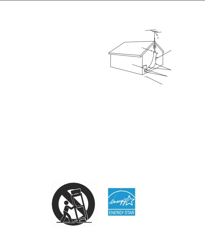
E X AMP L E O F ANT E NNA G R O UNDING
|
|
|
|
|
|
|
ANT E NNA |
|
|
|
|
|
|
|
|
|
|
|
|
|
|
|
L E AD IN W IR E |
G R O UND C L AMP |
|
|
|
||||
|
|
|
|
|
|
|
ANT E NNA |
|
|
|
|
|
|
|
DIS C HAR G E UNIT |
E L E C T R IC |
|
|
(NE C AR T IC L E 810-20) |
||||
|
|
|
|||||
S E R V IC E |
|
G R O UNDING |
|||||
E Q UIP ME NT |
|
||||||
|
C O NDUC T O R S |
||||||
|
|
|
|
|
|
||
|
|
|
|
|
|
(NE C AR T IC L E 810-21) |
|
|
|
|
|
|
|
G R O UND C L AMP S |
|
|
|
|
|
|
|
||
|
|
|
|
|
|||
|
|
|
|
|
|
P O W E R S E R V IC E G R O UNDING |
|
|
|
|
|
|
|
E L E C T R O DE S Y S T E M |
|
NE C — NAT IO NAL E L E C T R IC AL C O DE |
|
(NE C AR T 250, P AR T H) |
|||||
Outdoor Antenna Grounding
If an outside antenna or cable system is connected to the TV, be sure the antenna or cable system is grounded so as to provide some protection against voltage surges and built-up static charges.
Replacement Parts
When replacement parts are required, be sure the service technician has used replacement parts specified by the manufacturer or have the same characteristics as the original part. Unauthorized substitutions may result in fire, electric shock or other hazards.
The following TV models are
ENERGY STAR® qualified:
WD-65738, WD-73738, WD-82738
WD-65838, WD-73838, WD-82838
Products that earn the ENERGY STAR prevent greenhouse gas emissions by meeting strict energy efficiency guidelines set by the U.S. Environmental Protection Agency and the U.S. Department of Energy.
For assistance call 1(800) 332-2119
5
1 Basic Setup and Operation
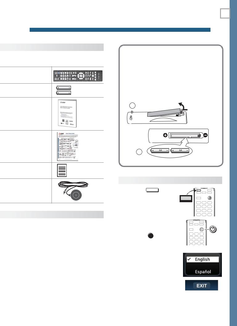
Package Contents
Please take a moment to review the following list of items to ensure that you have received everything.
Remote Control
Two AA Batteries |
AA |
|
AA |
Basic Owner’s Guide |
|
HDTV Quick Setup
Guide
Product Registration
Card
838 Series. Calibration
Microphone
Before You Begin
1.Review the important safety, installation, and operating information at the beginning of this book.
2.Choose a location for your TV.
•Allow at least four inches of space on all sides of the TV to help prevent overheating. Overheating may cause premature failure of the TV as well as shortened lamp life.
•Avoid locations where light may reflect off the screen.
•See the stand requirements on page 2.
3.Install the batteries in the remote control.
4.Plug the TV into an AC power outlet.
Installing the Remote Control
Batteries
1.Remove the remote control’s back cover by gently pressing in the tab and lifting off the cover.
2.Load the batteries, making sure the polarities
(+)and (-) are correct. For best results, insert the negative (-) end first.
3.Snap the cover back in place.
1 |
The remote |
|
control requires |
|
two AA |
|
batteries. |
2
First-Time Power-On
1. Press the TV |
key to |
TV |
|
ensure that the remote
control is in TV mode. |
TV |
|
2. Aim the emitter (bulb) end of the remote control at the TV and press the
POWER key . Wait for the
Welcome screen.
3.If you wish to change the menu language to Español, press  .
.
4.Press  to highlight EXIT. Press ENTER to clear the menu.
For assistance call 1(800) 332-2119

6 |
1. Basic Setup and Operation |
Remote Control
Sleep Timer
|
|
|
Number/letter keys |
|
|
|
Channel tuning, page 8 |
|
|
|
Pass code entry, page 26 |
|
|
|
Adds a separator in digital channel |
|
|
|
|
|
|
|
numbers. Clears some menu entries. |
MUTE |
Mutes the TV speakers. |
||
TOOLS |
Displays shortcuts for the number keys. |
||
|
|
|
Press to check if shortcuts are available |
|
|
|
for the current device. |
VOL |
Controls volume of TV speakers. |
||
CH |
Changes channels; moves to another |
||
PAGE |
page in a menu or list. |
||
ENTER Selects a channel number or menu item.
Navigation and adjustment controls
GUIDE ChannelView listings, page 15.
INFO TV status or TV help.
(PAUSE) Freezes a broadcast TV picture.
Record/Playback controls for external devices. Additional setup is required.
 Emitter End
 TV CAB/SAT DVD AUDIO VCR
Press the key for the device type to control. Leave in TV mode for normal TV viewing.
|
|
|
|
|
|
|
|
Powers TV on or off. |
|
|
|
|
|
|
|
LAST Returns to the previous channel. |
|
|
|
|
|
|
|
|
FAV |
Displays up to nine favorite |
|
|
|
|
|
|
|
||
|
|
|
|
|
|
|
||
|
|
|
|
|
|
|
|
sources. See page 14. |
|
|
|
|
|
|
|
FORMAT |
Changes picture shape, |
|
|
|
|
|
|
|
||
|
|
|
|
|
|
|
|
page 14 |
|
|
|
|
|
|
|
INTERNET |
Connects to internet content |
|
|
|
|
|
|
|
||
|
|
|
|
|
||||
|
|
|
|
|
|
|
|
provided by VUDU™. See |
|
|
|
|
|
|
|
|
|
|
|
|
|
|
|
|
|
|
|
|
|
|
|
|
|
|
page 19. |
|
|
|
|
|
|
|
INPUT |
Press to select a TV input. |
|
|
|
|
|
|
|
|
See page 8. |
|
|
|
|
AUDIO |
Audio adjustments, page 22 |
|
|
|
|
VIDEO |
Video adjustments, page 21 |
|
|
|
|
MENU |
Displays or clears the TV main |
|
|
|
|
||
|
|
|
|
||
|
|
|
|
|
menu (page 21). Also steps |
|
|
|
|
|
|
|
|
|
|
|
back one menu. |
|
|
|
|
EXIT |
Clears all menus. |
|
|
|
|
||
|
|
|
|
 838 Series. Special keys for use with NetCommand IR control. See the detailed owner’s guide at www.mitsubishi-tv.com.
The TV’s remote control can operate other audio/video devices using any of these methods:
•Program the remote control for the device (page 30).
•Set up HDMI Control for HDMI devices compatible with the TV.
•838 Series. Perform NetCommand setup for device keys.
See the detailed owner’s guide at www.mitsubishi-tv.com for information.
If You Turn Off the TV by Mistake
•Press POWER again, within about 60 seconds, to have the TV come back on immediately.
•If the STATUS indicator is green and blinking rapidly, (about 60 seconds after you shut off power), wait a few moments for the indicator to stop blinking and press POWER to turn the TV on again.
For assistance call 1(800) 332-2119
1. Basic Setup and Operation |
7 |
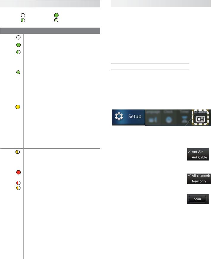
The STATUS Indicator
Key |
Off |
Steady On |
|
|
Slow Blinking |
Fast Blinking |
|
|
|
|
|
LED Color |
TV Condition |
|
|
|
|
||
None |
TV is powered off. Normal operation. |
||
|
|
||
|
|
||
Green |
TV is powered on. Normal operation. |
||
|
|
||
|
|
||
Green |
TV powered off, auto-on TV Timer is |
||
set. |
|
||
|
|
||
|
Normal operation. TV can be turned on |
||
|
at any time. |
|
|
|
|
||
Green |
TV just powered off and lamp is |
||
cooling. |
|
||
|
|
||
|
Sixty seconds after turning off TV, LED |
||
|
will start to blink. TV can be turned back |
||
|
on before blinking starts or after blink- |
||
|
ing stops, but not while the indicator is |
||
|
blinking. Normal operation. |
||
|
|
||
Yellow |
TV is too hot. The TV will display a |
||
warning message and shut off if it over- |
|||
|
|||
|
heats. |
|
|
•Ambient room temperature may be too high. Turn off the TV and let the room temperature drop.
•Clear blocked air vents. Ensure at least a four-inch clearance on all sides of the TV.
Yellow |
Lamp access door is not secure or no |
|
lamp installed. |
||
|
||
|
TV will not operate until lamp access |
|
|
door is secured. See Appendix A. |
|
|
|
|
Red |
Lamp failure. Replace the lamp. See |
|
Appendix A. |
||
|
||
|
|
|
Red/ |
TV may require service. |
|
|
||
Yellow |
• Hold power button on front panel for |
|
|
10 seconds to reset TV. |
•If LED continues to flash red and yellow after reset, turn off the TV and unplug it from the AC power source. Wait one minute and then plug the set back in.
•If LED continues to flash red and yellow, go to www.mitsubishi-tv.com or call 1-800-332-2119 to receive Authorized Service Center information.
You may be asked to count how many times the LED flashes each color to aid in troubleshooting.
Setting Up and Using TV Inputs
Using the ANT (Antenna) Input
If using an antenna or direct cable service (no cable box), connect the incoming coaxial cable to the TV’s ANT input. Refer to page 12.
You must perform a channel scan to enable reception of digital channels. If you skip this step, the TV will receive only analog channels. The channel scan will search for high-definition and standard-definition channels available in the local area.
Memorizing Channels with Channel Scan
For the ANT input
To start channel memorization
1.Power on the TV.
2.Press MENU and open the Setup > Channel menu.
First press  to navigate to the Setup icon, then use
  to highlight the Channel icon.
Start channel memorization from the Setup > Channel menu.
3.Press  to enter the menu.
4.Highlight Ant Air if connected to an over-the-air antenna. Highlight Ant Cable for service over direct cable (no cable box). Press ENTER to add a check.
5.For first-time setup, highlight All channels. To scan for channels not already in memory, highlight New only. Press ENTER to add a check.
6.Highlight Scan and press ENTER. Channel memorization may take up to 15 minutes to complete.
To stop channel memorization before completion, press CANCEL.
For assistance call 1(800) 332-2119
8 1. Basic Setup and Operation
Setting Up and Using TV Inputs, continued
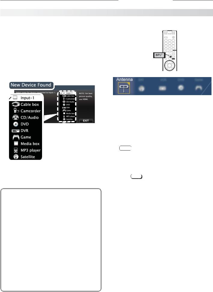
Setting Up Other Inputs |
Selecting an Input to Watch |
|
1. |
Power on the TV. |
|
2. |
Power on the devices to ensure detection. |
|
3. |
Connect one device to the TV, making note of the |
1. Press INPUT. |
|
TV input jack. |
|
|
The TV will display the New Device Found screen if |
|
|
the connection type is detectable. |
|
4. |
Highlight the device type in the on-screen list and |
|
|
press ENTER. The name you select here will appear |
|
|
in the Input Selection menu. |
|
Sample Input Selection menu, antenna input selected
2. Press
 to highlight an input icon.
3. Press ENTER to switch to the input.
Sample New Device
Found screen.
5.Press EXIT to close the New Device Found screen.
6.Repeat steps 3 through 5 for each additional device you want to add.
Tuning to Channels on the Antenna Input
•Enter the channel number using the number keys on the remote control and press ENTER.
•For a two-part digital channel, such as 3-1, press 3
—
CANCEL .
•Press CH /
/ to change channels one channel at a time.
•Press and hold CH /
/ to speed through channels.
•Press LAST to return to the previous channel.
•Use the Fav (Favorites) feature to tune to up to nine favorite channels. See page 14.
About Auto Input Sensing
This TV’s Easy Connect™ Auto Input Sensing feature detects most input connections automatically. Some exceptions are:
•A connection on the ANT input
•TV audio outputs (analog and digital)
•An HDMI-equipped device that is powered off. Power on the device first to ensure detection.
•Ethernet
Auto Input Sensing for Most Devices
When you first connect a device, the TV will:
a.Detect the connected device and automatically switch to it.
b.Prompt you to identify the device type.
c.Repeat these steps for other newly detected devices.
•Press GUIDE to display ChannelView channel listings, highlight a channel number, and press ENTER to tune.
For assistance call 1(800) 332-2119
1. Basic Setup and Operation |
9 |
|
|
|
|
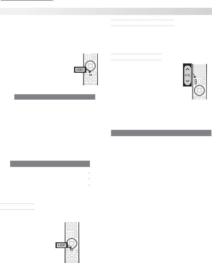
Basic TV Operation
Picture Settings
1.To get the best picture under different viewing conditions, set the Picture Mode first before changing other video settings. See page 21 for a description of the options.
a. Press VIDEO.
b. Press  until the Picture Mode option displays.
c. Press to make one of these selections:
Name |
When to Use |
|
Brilliant |
Under bright light |
|
Game |
With gaming consoles (inputs |
|
|
named Game or PC only) |
|
Bright |
For most daytime viewing |
|
Natural |
For most nighttime viewing |
|
2.Press to display the name of another adjustment.
3.Press
 to make the adjustment.
4.Wait a few seconds and the display will clear.
Additional picture options are available through the following menus:
Menu |
|
Page |
Picture > Picture Plus |
21 |
|
|
|
|
Picture > Perfect (838 series) |
22 |
|
|
|
|
Picture > 3D Mode |
16 |
|
|
|
|
Audio Controls
Changing the Audio Output
To switch from the internal TV speakers to an external sound system:
1. Press AUDIO.
2. Press to display the
TV Speakers option.
3. Press
 to change.
Changing Audio Settings (TV Speakers Only)
1.Press AUDIO.
2.Press to display the name of the adjustment you want. See page 22 for descriptions.
3.Press
 to change.
Controlling Sound Volume
• Press VOL /
/ to adjust the sound level of the TV speakers.
• See the full owner’s guide at www.mitsubishi-tv.com for methods of controlling A/V receiver volume.
More TV Features
Features covered in this Basic Owner’s Guide include:
Feature |
|
|
Page |
Parental controls (Lock menu) |
26 |
||
|
|
|
|
TV Clock. Set the TV Clock if you plan to use |
24 |
||
the TV Timer (page 24) or ChannelView (page |
|
|
|
15). |
|
|
|
|
|
|
|
Favorite sources |
14 |
||
|
|
|
|
ChannelView and custom channel collections |
15 |
||
|
|
|
|
Changing the input names that appear in the |
25 |
||
Input Selection menu (Inputs > Name menu) |
|
|
|
|
|
|
|
3D Video |
16 |
||
|
|
|
|
Internet video streaming with VUDU |
19 |
||
|
|
|
|
Digital camera images as composite video |
|
15 |
|
|
|||
|
|
|
|
838 Series. Listening to a wireless audio |
|
20 |
|
device with the TV speakers |
|
|
|
|
|
|
|
See the detailed Owner’s Guide at www.mitsubishi-tv.com for more on the features described here and to learn about other features, including:
•HDMI control (CEC) of other A/V devices
•838 Series. NetCommand IR control of other A/V devices. Use of NetCommand requires purchase of IR emitter cables available from Mitsubishi.
•838 Series. Center and rear channel audio output
•838 Series. Using an external subwoofer.
•838 Series. Viewing photo files from a USB device.
For assistance call 1(800) 332-2119

10 2 TV Connections
Main Connection Panel
838 Series Jacks. See the full owner’s guide at www.mitsubishi-tv.com.
 SUB
SUB  CENTER WOOFER INPUT OUTPUT
AUDIO/SURROUND
OUTPUT
(838 series, page 23)
DIGITAL |
DVI/PC AUDIO |
AUDIO |
AUDIO/SURROUND |
|||||||
AUDIO |
INPUT |
OUTPUT |
||||||||
R |
|
OUTPUT |
|
L |
||||||
|
|
|||||||||
OUTPUT |
page 11 |
(page |
13) |
|
|
|
|
|
||
(page 13) |
|
|
|
|
|
|
|
|
|
|
|
|
|
|
|
|
|
|
|
|
|
DIGITAL |
DVI/PC AUDIO |
|
|
AUDIO |
|
|
||
AUDIO |
R |
|
INPUT L |
R |
|
OUTPUT |
|
L |
|
|
|
||||||
OUTPUT |
|
|
|
|
|
|
|
|
ANT
IR-NetCommand
Output/EXTERNAL
CONTROLLER INPUT
HDMI
LAN
1 2 3
|
|
|
|
|
|
|
|
|
|
|
|
|
|
|
|
|
|
|
|
|
|
|
|
|
|
|
|
|
|
|
|
|
|
|
|
|
|
|
|
|
|
|
|
|
|
|
|
|
|
|
|
|
|
|
|
|
|
|
|
HDMI |
USB |
|
|
|
|
|
|
|
|
|
|
|
|
|
|
|
|
|
|
(Accessory power |
|
LAN |
|||||||||||||||||
page 11 |
|
||||||||||||||||||
on all models; |
(Ethernet, port |
||||||||||||||||||
|
|||||||||||||||||||
|
738 Series, wireless |
page 19) |
|||||||||||||||||
|
adapter, page 19) |
||||||||||||||||||
|
|
|
|
|
|
|
|
|
|
|
|
|
|
|
|
|
|
||
|
|
|
|
|
|
|
|
|
|
|
|
|
|
|
|
|
|
|
|
|
|
|
|
|
|
|
|
VIDEO |
Pb |
2 |
3D |
|||||||
|
|
|
|
|
|
|
|
|
|
|
|
|
INPUT |
|||||
|
|
|
|
|
|
|
|
|
|
|
|
|
GLASSES |
|||||
|
|
|
|
|
|
|
|
|
|
|
|
|
|
EMITTER |
||||
|
|
|
|
|
|
|
|
|
|
|
|
|
INPUT 1 |
|
|
|
|
|
|
|
|
|
|
|
|
|
VIDEO |
|
|
|
|
|
|
|
ANT |
||
|
|
|
|
|
|
|
|
|
|
|
|
|
||||||
|
|
|
|
|
|
|
|
|
|
|
|
|
||||||
|
|
|
|
|
|
|
|
|
|
|
|
|
|
|
|
page 12 |
||
R |
|
AUDIO |
|
|
L |
(480i / 480p / 720p / 1080i) |
|
|
|
|
|
|||||||
|
|
|
|
|
|
|
|
|
|
|||||||||
|
|
|
|
|
|
|
|
|
|
|
|
|
|
|
||||
|
|
|
|
|
|
|
|
|
|
|
|
|
|
|
||||
|
|
|
|
|
|
|
|
|
|
|
|
|
|
|
|
|
|
|
|
R & L |
|
|
|
|
VIDEO |
|
|
|
|
3D GLASSES |
|
||||||
|
|
|
|
|
|
Y Pb Pr |
|
|
||||||||||
Analog |
|
|
|
(composite |
|
|
|
EMITTER |
|
|||||||||
|
|
|
|
(component |
|
|
|
|||||||||||
Audio |
|
|
|
|
video) |
|
video) |
|
|
(page 16) |
|
|||||||
|
Input |
|
|
|
|
|
|
|
|
|
|
|
|
|
||||
|
|
|
|
|
|
|
|
|
|
|
|
|
|
|
|
|||
|
|
|
|
|
|
|
|
|
|
|
|
|
|
|
|
|
|
|
838 Series Side Inputs
INPUT 3
Pr Pb Y/ VIDEO L AUDIO R USB HDMI 4
|
|
|
|
|
|
|
|
|
|
|
|
|
|
|
|
|
|
|
|
|
|
|
|
|
|
|
|
|
|
Y Pb Pr |
|
|
|
USB |
|
|
|
|
|
|
|
|
|
|
|
|
|
|
|
|
|
|
|||
|
|
|
|
|
|
|
|
|
|
|
|||
|
|
|
|
|
|
|
|
|
|
|
|||
|
|
VIDEO |
R & L |
HDMI |
|||||||||
|
|
||||||||||||
|
|
(component |
(composite |
Analog |
(page 19) |
|
|
|
|
|
|
||
|
|
video) |
video) |
Audio |
|
|
|
|
|
|
|
|
|
|
|
|
|
|
|
|
|
|
|||||
|
|
|
|
|
|
|
|
|
|||||
|
|
|
|
|
Input |
|
|
|
|
|
|
|
|
Auto Input Sensing
The TV’s Auto Input Sensing feature automatically recognizes many connections and prompts you to identify the type of device connected. See page 8 for more on Auto Input Sensing.
Connection Types and Audio/Video Quality
|
|
|
|
|
|
VIDEO QUALITY |
|
|
|
|
|
|
|
AUDIO QUALITY |
|||||||||
|
|
BEST |
|
GOOD |
|
|
BEST |
|
|
GOOD |
|||||||||||||
|
|
|
|
|
|
|
|
|
|
|
Component |
Composite |
|
|
|
|
|
Digital |
L/R Analog |
||||
HDMI HDMI-to-DVI |
Video |
Video |
HDMI |
Audio |
Audio |
||||||||||||||||||
|
|
|
|
|
|
|
|
|
|
|
|
|
|
|
|
|
|
|
|
|
|
|
|
|
|
|
|
|
|
|
|
|
|
|
|
|
|
|
|
|
|
|
|
|
|
|
|
|
|
|
|
|
|
|
|
|
|
|
|
|
|
|
|
|
|
|
|
|
|
|
|
|
|
|
|
|
|
|
|
|
|
|
|
|
|
|
|
|
|
|
|
|
|
|
|
|
|
|
|
|
|
|
|
|
|
|
|
|
|
|
|
|
|
|
|
|
|
|
|
|
|
|
|
|
|
|
|
|
|
|
|
|
|
|
|
|
|
|
|
|
|
|
|
|
|
|
|
|
|
|
|
|
|
|
|
|
|
|
|
|
|
|
|
|
|
|
|
|
|
|
|
|
|
|
|
|
|
|
|
|
|
|
|
|
|
|
|
|
|
|
|
|
|
|
|
|
|
|
|
|
|
|
|
|
|
|
|
|
|
|
|
|
|
|
|
|
|
|
|
|
|
|
|
|
|
|
|
|
|
|
|
|
|
|
|
|
|
|
|
For assistance call 1(800) 332-2119
2. TV Connections |
11 |
HDMI Device |
Y Pb Pr Component Video Device |
|
Mitsubishi recommends using high-speed HDMI |
Required: |
|
cables to connect newer devices incorporating HDMI |
• |
RCA-type component video cables |
technology. |
• |
Left/right analog audio cables. |
DIGITAL |
|
AUDIO |
|
DVI/PC AUDIO |
ANT |
||
AUDIO |
R |
L |
R |
INPUT |
L |
|
|
OUTPUT |
OUTPUT |
|
|||||
Y/VIDEO |
Pb |
Pr |
2 |
|
DIGITAL |
|
AUDIO |
|
DVI/PC AUDIO |
||
|
AUDIO |
R |
L |
R |
INPUT |
L |
|||||
|
|
|
INPUT |
3D |
OUTPUT |
OUTPUT |
|||||
|
|
|
GLASSES |
|
|
|
|
|
|
|
|
|
|
|
|
EMITTER |
|
|
|
|
|
|
|
|
|
|
|
|
1 |
|
|
|
|
|
|
|
|
INPUT |
Y/VIDEO |
Pb |
Pr |
|
|
Y/VIDEO |
Pb |
Pr |
HDMI |
|
|
|
|
|
|
|
|
||||
R |
AUDIO |
L |
(480i / 480p / 720p / 1080i) |
|
LAN |
|
|
|
|
|
|
Y/VIDEO |
|
Pb |
Pr |
R |
|
L |
|
|
||
AUDIO |
(480i / 480p / 720p / 1080i) |
|||||
TV main panel
INPUT 1 INPUT 2
ANT
3D  GLASSES
EMITTER
|
HDMI-to-HDMI |
TV main panel |
|
cable |
|
|
|
|
|
|
|
Y/ VIDEO |
Pb |
Pr |
R– AUDIO –L
Any HDMI device
HDMI and Digital Surround Sound
738 Series. The TV’s HDMI inputs can receive digital stereo audio signals only when using the TV speakers.
838 Series. The TV’s HDMI inputs can receive digital surround sound from an HDMI device. Use an HDMI connection if you want to hear digital surround sound from the TV’s internal speaker array.
|
|
|
|
|
|
|
|
|
|
|
|
|
|
|
Audio |
|
Component |
||
cables |
|
video cables |
||
|
|
|
|
|
|
|
|
|
|
|
|
|
|
|
Incoming from cable service or satellite dish
|
|
|
|
L |
R |
|
Y Pb Pr |
||
|
|
|
|
|
|||||
|
|
|
|
AUDIO |
|
|
|
|
|
|
|
|
|
|
|
|
|
|
|
|
|
or |
Component video |
|
|
||||
CABLE IN |
|
|
|||||||
SATELLITE IN |
|
device |
|||||||
DVI Video Device |
Composite Video Device |
|
Required: |
Required: |
|
• DVI-to-HDMI cable or DVI/HDMI adapter and |
• |
Composite video cable (usually yellow) |
HDMI cable |
• |
Analog stereo audio cables. |
•Left/right analog audio cables
|
|
|
|
|
|
|
|
|
DIGITAL |
|
AUDIO |
|
DVI/PC AUDIO |
|
|
ANT |
|||
|
|
|
|
|
|
|
|
|
AUDIO |
|
R |
L |
R |
INPUT |
L |
|
|
|
|
|
|
|
|
|
|
|
|
|
OUTPUT |
OUTPUT |
|
|
|
||||||
DIGITAL |
DVI/PC AUDIO |
|
AUDIO |
|
|
|
ANT |
|
|
|
|
|
|
|
|
|
|
||
AUDIO |
R |
INPUT |
L |
|
R OUTPUT |
L |
|
|
|
|
|
Y/VIDEO |
|
Pb |
Pr |
|
2 |
|
|
OUTPUT |
|
|
|
|
|
|
|
|
3D |
Y/VIDEO |
|||||||||
|
|
|
|
|
|
|
|
|
HDMI |
|
|
|
|
|
|
|
INPUT |
||
|
|
|
|
|
|
|
|
|
|
|
|
|
|
|
R |
GLASSES |
|||
|
|
|
|
|
|
|
|
|
LAN |
|
|
|
|
|
|
AUDIOTTER L |
|||
|
|
|
|
|
|
|
|
|
|
|
|
|
|
|
|
– |
|
EM |
– |
|
|
Y/VIDEO |
|
Pb |
Pr |
|
|
|
|
|
|
|
|
|
|
|
1 |
|
|
LAN |
|
|
|
INPUT2 |
GLASSES |
|
|
|
Y/VIDEO |
|
Pb |
Pr |
|
INPUT |
|
|
|||
|
|
|
|
|
|
|
|
3D |
|
|
|
|
|
|
|
|
|
|
|
|
|
|
|
|
|
|
|
EMITTER |
R |
AUDIO |
L |
|
|
(480i / 480p / 720p / 1080i) |
|
|
|
|
|
|
|
|
|
DVI/PC AUDIO |
1 |
|
|
|
|
|
|
|
|||||||
|
|
|
|
INPUT |
|
|
|
|
|
|
|
|
|
|
|
|
|||
|
|
Y/VIDEO |
|
R |
INPUT |
L |
|
|
|
|
|
|
|
|
|
|
|
|
|
|
|
|
Pb |
Pr |
|
|
|
|
|
|
|
|
|
|
|
|
|
|
|
R AUDIO |
L |
|
|
(480i / 480p / 720p / 1080i) |
|
|
|
L |
|
|
|
|
|
|
|
|
|
|
|
|
|
|
|
|
|
|
|
|
|
|
|
|
|
|
|
|
|
|
|
TV main panel
TV main panel
L 


|
|
|
|
|
DVI-to-HDMI |
|
|
|
R |
Audio |
|
||
|
|
|
|
|
|
|
|
|
|||||
|
|
|
|
|
Audio |
|
|
cables |
|
||||
|
DVI OUT |
|
|
cable |
|
AUDIO OUT |
Composite |
||||||
|
|
|
|
|
|
cables |
|
|
video cable |
||||
R |
|
|
|
|
|
|
|
|
|
||||
|
|
|
|
|
|
|
|
|
|||||
|
|
|
|
|
|
|
|
|
|
|
|||
L |
|
|
|
|
|
COMPOSITE |
|
|
|||||
|
|
|
|
|
|
|
|
|
|
||||
|
AUDIO |
|
|
|
|
|
|
VIDEO OUT VCR or other device with |
|
||||
|
|
|
Digital DVI |
|
|
|
|
|
|
composite video output |
|
||
|
|
|
|
|
|
|
|
|
|
||||
|
|
|
device |
|
|
|
|
|
|
|
|
||
|
|
|
|
|
|
|
|
|
|
|
|||
|
|
|
|
|
|
|
|
|
|
|
|||
For assistance call 1(800) 332-2119
12 |
2. TV Connections |
Antenna or Cable TV Service
Connect the incoming cable to the TV’s ANT input.
Antenna 
Direct cable (no cable box)
Cable TV |
|
or |
|||||
|
|
|
|
|
|
|
|
service |
|
|
|
|
|
|
|
|
IN |
OUT |
|
|
|
|
|
|
Older cable box |
|
or |
||||
|
|||||||
|
|||||||
Not recommeded. Other |
|
|
|
|
|||
|
|
|
|
||||
connection types provide |
|
|
|
|
|||
|
|
|
|
||||
better quality audio and video. |
|||||||
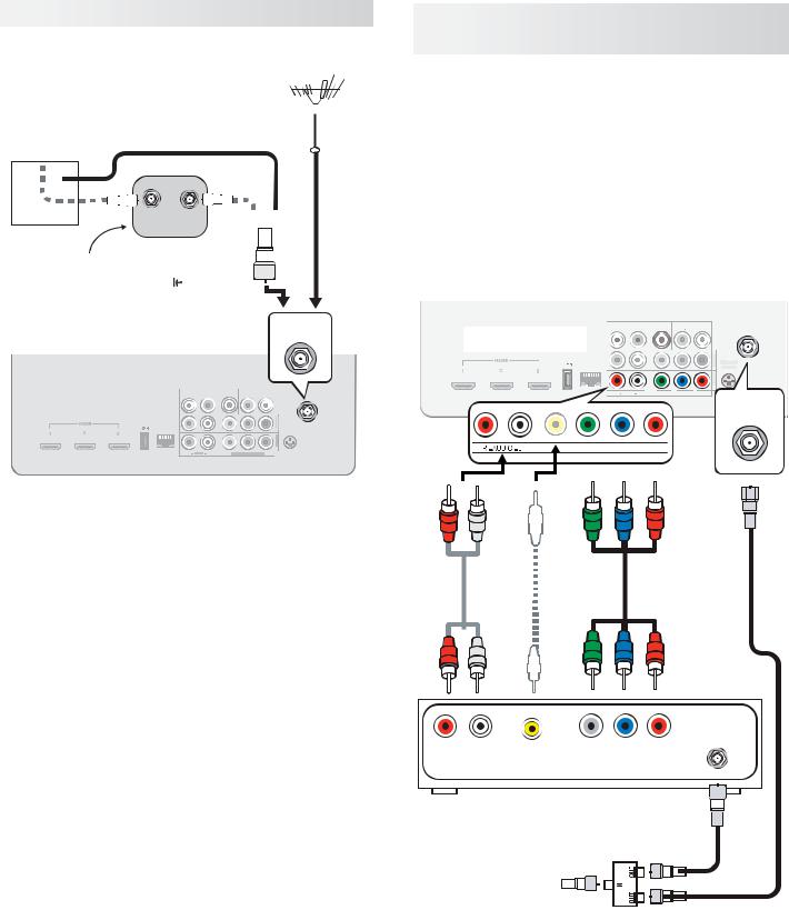
VCR or DVD Recorder to an Antenna or Wall Outlet Cable
Required:
1.Video cables
1a. Component video cables (red/blue/green) or
1b. Composite video cable (usually yellow)
2.Left/right analog audio cables.
3.Two-way RF splitter
4.Two coaxial cables
Note: If your recording device has an analog-only tuner, you must use a digital converter box to enable recording of digital broadcasts.
TV main panel
LAN
ANT |
DIGITAL |
|
AUDIO |
|
DVI/PC AUDIO |
||
AUDIO |
R |
L |
R |
INPUT |
L |
||
OUTPUT |
OUTPUT |
||||||
TV main panel
Y/VIDEO |
Pb |
Pr |
LAN
DIGITAL |
|
AUDIO |
|
DVI/PC AUDIO |
|
ANT |
AUDIO |
L |
Y/VIDEO |
Pb |
Pr |
||
AUDIO |
R |
L |
R |
INPUT |
L |
|
R |
|
(480i / 480p / 720p / 1080i) |
||||
OUTPUT |
OUTPUT |
|
|
|
|
|
|
|
|||||
|
|
Y/VIDEO |
|
Pb |
Pr |
|
2 |
3D |
|
|
|
|
|
|
|
|
|
|
|
|
INPUT |
|
|
|
|
|
|
|
|
|
|
|
|
|
GLASSES |
|
|
|
|
|
|
|
|
|
|
|
|
|
|
EMITTER |
|
|
|
|
|
|
|
|
|
|
|
|
|
Y/VIDEO |
Y/VIDEO |
Pb |
Pr |
||
|
|
|
|
|
|
1 |
|
|
|
|
|
|
|
|
|
|
|
|
|
INPUT |
|
|
|
|
|
|
|
|
|
|
|
|
|
|
|
|
|
|
|
|
|
|
|
Y/VIDEO |
Pb |
Pr |
|
|
|
|
|
|
|
||
R |
AUDIO |
L |
(480i / 480p / 720p / 1080i) |
|
|
|
|
|
|
|
|
||
ANT
|
2 |
|
3D |
|
INPUT |
|
|
|
|
GLASSES |
|
|
|
||
|
|
|
EMITTER |
|
|
|
|
INPUT1 |
|
|
ANT
2.
Composite video cable
1b.
or
1a.
|
|
|
|
|
|
ANTENNA |
|||
|
|
|
|
|
|||||
|
R |
L |
COMPOSITE |
COMPONENT |
|
|
IN |
||
|
|
|
|
|
|||||
|
AUDIO OUT |
VIDEO OUT |
VIDEO OUT |
|
|
|
|
||
|
|
|
|
|
|
|
|
|
|
|
|
|
|
|
|
|
|
|
|
|
|
|
|
|
|
|
|
|
|
DVD Recorder or VCR
3. |
|
|
|
|
|
4. |
|||||||||
|
|
RF Splitter |
|||||||||||||
|
|
|
|
||||||||||||
Incoming cable |
|
|
|
|
|
|
|
|
4. |
||||||
|
|
|
|
|
|
|
|
||||||||
|
|
|
|
|
|||||||||||
|
|
|
|
|
|
|
|
|
|
|
|
|
|
|
|
|
|
|
|
|
|
|
|
|
|
|
|
|
|
|
|
|
|
|
|
|
|
|
|
|
|
|
|
|
|
|
|
|
|
|
|
|
|
|
|
|
|
|
|
|
|
|
|
|
|
|
|
|
|
|
|
|
|
|
|
|
|
|
|
For assistance call 1(800) 332-2119
 Loading...