


 Loading...
 MITSUBISHI ELECTRIC
MELFA
Industrial Robots
Specifications Manual
RV-1A/RV-2AJ Series
Art. no.: 132309 05 07 2002 BFP-A8050-F
 MITSUBISHI ELECTRIC INDUSTRIAL AUTOMATION


 Safety Precautions
Always read the following precautions and the separate "Safety Manual" before starting use of the robot to learn the required measures to be taken.
|
|
CAUTION |
All teaching work must be carried out by an operator who has received special training. |
|
|||
|
|
||
|
|
|
(This also applies to maintenance work with the power source turned ON.) |
|
|
|
→ Enforcement of safety training |
|
|
CAUTION |
For teaching work, prepare a work plan related to the methods and procedures of oper- |
|
|
||
|
|
||
|
|
||
|
|
|
ating the robot, and to the measures to be taken when an error occurs or when restart- |
|
|
|
ing. Carry out work following this plan. (This also applies to maintenance work with the |
|
|
|
power source turned ON.) |
|
|
|
→ Preparation of work plan |
|
|
WARNING |
Prepare a device that allows operation to be stopped immediately during teaching work. |
|
|
||
|
|
||
|
|
||
|
|
|
|
|
|
|
(This also applies to maintenance work with the power source turned ON.) |
|
|
|
→ Setting of emergency stop switch |
|
|
CAUTION |
During teaching work, place a sign indicating that teaching work is in progress on the |
|
|
||
|
|
||
|
|
||
|
|
|
start switch, etc. (This also applies to maintenance work with the power source turned |
|
|
|
ON.) |
|
|
|
→ Indication of teaching work in progress |


 WARNING


 CAUTION


 CAUTION
Provide a fence or enclosure during operation to prevent contact of the operator and robot.
→ Installation of safety fence
Establish a set signaling method to the related operators for starting work, and follow this method.
→ Signaling of operation start
As a principle turn the power OFF during maintenance work. Place a sign indicating that maintenance work is in progress on the start switch, etc.
→ Indication of maintenance work in progress
|
|
CAUTION |
Before starting work, inspect the robot, emergency stop switch and other related |
|
|||
|
|
||
|
|
|
devices, etc., and confirm that there are no errors. |
|
|
|
→ Inspection before starting work |

The points of the precautions given in the separate "Safety Manual" are given below. Refer to the actual "Safety Manual" for details.


 CAUTION Use the robot within the environment given in the specifications. Failure to do so could lead to a drop or reliability or faults. (Temperature, humidity, atmosphere, noise environ- ment, etc.)


 CAUTION


 CAUTION


 CAUTION


 CAUTION


 CAUTION


 WARNING


 WARNING

 CAUTION


 WARNING


 CAUTION


 CAUTION


 CAUTION


 CAUTION


 WARNING
Transport the robot with the designated transportation posture. Transporting the robot in a non-designated posture could lead to personal injuries or faults from dropping.
Always use the robot installed on a secure table. Use in an instable posture could lead to positional deviation and vibration.
Wire the cable as far away from noise sources as possible. If placed near a noise source, positional deviation or malfunction could occur.
Do not apply excessive force on the connector or excessively bend the cable. Failure to observe this could lead to contact defects or wire breakage.
Make sure that the workpiece weight, including the hand, does not exceed the rated load or tolerable torque. Exceeding these values could lead to alarms or faults.
Securely install the hand and tool, and securely grasp the workpiece. Failure to observe this could lead to personal injuries or damage if the object comes off or flies off during operation.
Securely ground the robot and controller. Failure to observe this could lead to malfunc- tioning by noise or to electric shock accidents.
Indicate the operation state during robot operation. Failure to indicate the state could lead to operators approaching the robot or to incorrect operation.
When carrying out teaching work in the robot's movement range, always secure the pri- ority right for the robot control. Failure to observe this could lead to personal injuries or damage if the robot is started with external commands.
Keep the jog speed as low as possible, and always watch the robot. Failure to do so could lead to interference with the workpiece or peripheral devices.
After editing the program, always confirm the operation with step operation before starting automatic operation. Failure to do so could lead to interference with peripheral devices because of programming mistakes, etc.
Make sure that if the safety fence entrance door is opened during automatic operation, the door is locked or that the robot will automatically stop. Failure to do so could lead to personal injuries.
Never carry out modifications based on personal judgments, or use non-designated maintenance parts.
Failure to observe this could lead to faults or failures.
When the robot arm has to be moved by hand from an external area, do not place hands or fingers in the openings. Failure to observe this could lead to hands or fingers catching depending on the posture.


 CAUTION Do not stop the robot or apply emergency stop by turning the robot controller's main power OFF.
If the robot controller main power is turned OFF during automatic operation, the robot accuracy could be adversely affected.
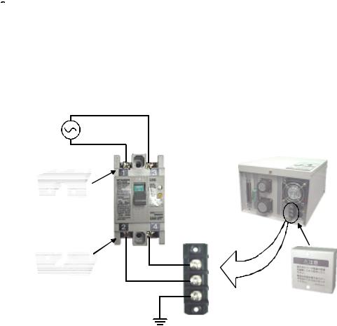
C.Precautions for the basic configuration are shown below.(When CR1-571 is used for the controller.)


 CAUTION Provide an earth leakage breaker that packed together on the primary power supply of the controller as protection against electric leakage. Confirm the set- ting connector of the input power supply voltage of the controller, if the type which more than one power supply voltage can be used. Then connect the power supply.
Failure to do so could lead to electric shock accidents.
Power supply *RV-1A/2AJ series and RP-1AH/3AH/5AH series: Single phase 90-132VAC, 180-253VAC. *Except the above: Single phase 180-253VAC.
Rear side of controller
Earth leakage breaker
(NV)
Cover
Terminal
Cover
Terminal cover
Protective earth terminal
(PE)
■ Revision history
Date of print |
Specifications No. |
Details of revisions |
|
|
|
|
|
|
2000-02-08 |
BFP-A8050Z |
First print |
|
|
|
2000-04-05 |
BFP-A8050 |
Formal style |
|
|
|
2000-06-09 |
BFP-A8050-A |
The power supply voltage of CR1 controller was corrected |
|
|
|
2001-03-12 |
BFP-A8050-B |
Error in writing correction. |
|
|
|
2002-01-23 |
BFP-A8050-C |
LNG, RLNG and MESNGLSW parameters were added. |
|
|
Error in writing correction. |
|
|
|
2002-04-01 |
BFP-A8050-D |
CR1-MB (controller protction box) was added. |
|
|
Error in writing correction. |
|
|
|
2002-06-03 |
BFP-A8050-E |
RV-1AC-SB, RV-2AJC-SB was added. |
|
|
Error in writing correction. |
|
|
|
2002-07-05 |
BFP-A8050-F |
The description of input/output circuit terminal was corrected. |
|
|
Error in writing correction. |
|
|
|
|
|
|
■ Introduction
The "RV-1A" and "RV-2AJ" are compact industrial robots developed with Mitsubishi's advanced technology. These robots respond to users needs for compact and flexible production facilities generated due to the recent diffusion of compact and highly accuracy products such as personal computer related devices, information termi- nal devices and compact electronic devices for mounting on vehicles, and due to shorter product life cycles.
However, to comply with the target application, a work system having a well-balanced robot arm, peripheral devices or robot and hand section must be structured.
When creating these standard specifications, we have edited them so that the Mitsubishi robot's characteristics and specifications can be easily understood by users considering the implementation of robots. However, if there are any unclear points, please contact your nearest Mitsubishi branch or dealer.
Mitsubishi hopes that you will consider these standard specifications and use our robots.
In this manual, the specifications regarding the robot arm are given in Page 5, "2 Robot arm" and following, and the specifications regarding the controller are given in Page 38, "3 Controller" and following. Refer to the correspond- ing sections for details on the specifications, options and maintenance parts, etc.
Note:
No part of this manual may be reproduced by any means or in any form, without prior consent from Mitsubishi.
The contents of this manual are subject to change without notice.
The specifications values are based on Mitsubishi standard testing methods.
The information contained in this document has been written to be accurate as much as possible. Please inter- pret that items not described in this document "cannot be performed.".
Please contact your nearest dealer if you find any doubtful, wrong or skipped point.
|
Contents |
|
|
|
Page |
1 General configuration .................................................................................................................................................................... |
1-1 |
|
1.1 Structural equipment ............................................................................................................................................................. |
1-1 |
|
1.1.1 Standard structural equipment .................................................................................................................................. |
1-1 |
|
1.1.2 Shipping special specifications ................................................................................................................................... |
1-1 |
|
1.1.3 Options ................................................................................................................................................................................. |
1-1 |
|
1.1.4 Maintenance parts ........................................................................................................................................................... |
1-1 |
|
1.2 |
Contents of the structural equipment ............................................................................................................................ |
1-2 |
1.2.1 Robot arm ........................................................................................................................................................................... |
1-2 |
|
1.3 |
Controller .................................................................................................................................................................................... |
1-3 |
1.4 |
Contents of the Option equipment and special specification .............................................................................. |
1-4 |
2 Robot arm ........................................................................................................................................................................................... |
2-5 |
|
2.1 |
Standard specifications ........................................................................................................................................................ |
2-5 |
2.2 |
Definition of specifications .................................................................................................................................................. |
2-6 |
2.2.1 Pose repeatability and distance accuracy ............................................................................................................ |
2-6 |
|
2.2.2 Rated load (mass capacity) ......................................................................................................................................... |
2-7 |
|
2.2.3 Protection specifications and working environment ......................................................................................... |
2-8 |
|
|
(1) Types of protection specifications ...................................................................................................................... |
2-8 |
2.2.4 Clean specifications ........................................................................................................................................................ |
2-9 |
|
|
(1) Types of clean specifications ................................................................................................................................. |
2-9 |
2.3 |
Names of each part of the robot .................................................................................................................................... |
2-10 |
2.4 |
Outside dimensions Operating range diagram ........................................................................................................ |
2-11 |
|
(1) RV-1A/1AC-SB ........................................................................................................................................................ |
2-11 |
|
(2) RV-2AJ/2AJC-SB ................................................................................................................................................... |
2-12 |
|
(3) Mechanical interface and Installation surface of RV-1A/2AJ, RV-1AC-SB/2AJC-SB .......... |
2-13 |
2.5 |
Tooling ........................................................................................................................................................................................ |
2-14 |
2.5.1 Wiring and piping for hand .......................................................................................................................................... |
2-14 |
|
|
(1) RV-1A/2AJ (General environment) .................................................................................................................. |
2-14 |
|
(2) RV-1AC-SB/2AJC-SB (Clean specification) .............................................................................................. |
2-15 |
2.5.2 Internal air piping ............................................................................................................................................................ |
2-16 |
|
2.5.3 Internal wiring for the pneumatic hand output cable ...................................................................................... |
2-16 |
|
2.5.4 Internal wiring for the hand check input cable .................................................................................................. |
2-16 |
|
2.5.5 Wiring and piping system diagram for hand ......................................................................................................... |
2-17 |
|
|
(1) RV-1A/2AJ (General environment) .................................................................................................................. |
2-17 |
|
(2) RV-1AC-SB/2AJC-SB (Clean specification) .............................................................................................. |
2-19 |
2.5.6 Electrical specifications of hand input/output .................................................................................................. |
2-21 |
|
2.5.7 Air supply circuit example for the hand ............................................................................................................... |
2-22 |
|
2.6 |
Shipping special specifications, options, and maintenance parts ...................................................................... |
2-23 |
2.6.1 Shipping special specifications ................................................................................................................................. |
2-23 |
|
|
(1) Machine cable extension ........................................................................................................................................ |
2-24 |
2.7 |
Options ....................................................................................................................................................................................... |
2-26 |
|
(1) Motorized hand set ................................................................................................................................................... |
2-27 |
|
(2) Pneumatic hand set .................................................................................................................................................. |
2-29 |
|
(3) Solenoid valve set ..................................................................................................................................................... |
2-31 |
|
(4) Hand input cable ........................................................................................................................................................ |
2-33 |
|
(5) Hand output cable ..................................................................................................................................................... |
2-34 |
|
(6) Hand curl tube ............................................................................................................................................................ |
2-35 |
|
(7) Hand adapter ............................................................................................................................................................... |
2-36 |
2.8 |
Maintenance parts ................................................................................................................................................................. |
2-37 |
3 Controller .......................................................................................................................................................................................... |
3-38 |
|
3.1 |
Standard specifications ...................................................................................................................................................... |
3-38 |
3.1.1 Standard specifications ............................................................................................................................................... |
3-38 |
|
3.1.2 Protection specifications and operating supply ................................................................................................ |
3-39 |
|
3.2 |
Names of each part .............................................................................................................................................................. |
3-40 |
3.3 |
Outside dimensions/Installation dimensions .............................................................................................................. |
3-42 |
i
|
|
|
Page |
3.3.1 Outside dimensions ...................................................................................................................................................... |
3-42 |
||
3.3.2 Installation dimensions ................................................................................................................................................ |
3-43 |
||
3.4 |
External input/output ......................................................................................................................................................... |
3-44 |
|
3.4.1 Types .................................................................................................................................................................................. |
3-44 |
||
3.4.2 Explanation ....................................................................................................................................................................... |
3-44 |
||
3.5 |
Dedicated input/output ...................................................................................................................................................... |
3-45 |
|
3.6 |
Emergency stop input/output ......................................................................................................................................... |
3-47 |
|
3.6.1 Connection of the external emergency stop ..................................................................................................... |
3-47 |
||
3.6.2 Door switch function ................................................................................................................................................... |
3-48 |
||
3.7 |
Parallel input/output unit .................................................................................................................................................. |
3-49 |
|
3.8 |
Options ...................................................................................................................................................................................... |
3-53 |
|
|
(1) Teaching pendant (T/B) ........................................................................................................................................ |
3-54 |
|
|
(2) |
Pneumatic hand interface ..................................................................................................................................... |
3-57 |
|
(3) |
Controller protection box ...................................................................................................................................... |
3-59 |
|
(4) |
Expansion option box .............................................................................................................................................. |
3-62 |
|
(5) |
Parallel I/O unit ......................................................................................................................................................... |
3-64 |
|
(6) |
External I/O cable .................................................................................................................................................... |
3-72 |
|
(7) |
Personal computer cable ....................................................................................................................................... |
3-74 |
|
(8) |
Personal computer support software/Personal computer support software mini ....................... |
3-76 |
3.9 |
Maintenance parts ................................................................................................................................................................ |
3-78 |
|
4 Software |
........................................................................................................................................................................................... |
4-79 |
|
4.1 |
List of commands ................................................................................................................................................................. |
4-79 |
|
|
(1) The procedure of robot language selection ................................................................................................... |
4-79 |
|
|
(2) |
MELFA-BASIC commands ..................................................................................................................... |
........ 4-80 |
|
(3) |
MOVEMASTER commands ................................................................................................................................... |
4-82 |
4.2 |
List of parameters ................................................................................................................................................................ |
4-85 |
|
|
(1) List of parameters .................................................................................................................................................... |
4-85 |
|
|
(2) |
Change the display language / .............................................................................. |
4-87 |
5 Safety ...................................................................................................................... |
.......................................................................... |
5-88 |
|
5.1 |
Safety ........................................................................................................................................................................................ |
5-88 |
|
5.1.1 Self-diagnosis stop functions .................................................................................................................................. |
5-88 |
||
5.1.2 External input/output signals that can be used for safety protection measures ............................. |
5-88 |
||
5.1.3 Precautions for using robot ...................................................................................................................................... |
5-89 |
||
5.1.4 Safety measures for automatic operation .......................................................................................................... |
5-89 |
||
5.1.5 Safety measures for teaching .................................................................................................................................. |
5-89 |
||
5.1.6 Safety measures for maintenance and inspections, etc. ............................................................................. 5-89 |
|||
5.1.7 Examples of safety measures .................................................................................................................................. |
5-90 |
||
5.2 |
Working environment ........................................................................................................................................................... |
5-91 |
|
5.3 |
Precautions for handling .................................................................................................................................................... |
5-91 |
|
6Appendix .............................................................................................................................................................................. |
|
Appendix-92 |
|
Appendix 1 Specifications discussion material ........................................................................................... |
Appendix-92 |
||
ii

1General configuration
1 General configuration
1.1 Structural equipment
Structural equipment consists of the following types.
1.1.1 Standard structural equipment
The following items are enclosed as a standard. (1) Robot arm
(2)Controller
(3)Machine cable
(4)Robot arm installation bolts
(5)Instruction manual, Safety manual
(6)Guarantee card
1.1.2 Shipping special specifications
Part of the standard structural equipment is changed at the time of factory shipment. Consequently, kindly con- firm the delivery date.
To make changes to the specifications after shipment, service work must be performed at the work site or the robot must be returned for service.
1.1.3 Options
Installation is possible after shipment. Customer needs to perform the installation work.
1.1.4 Maintenance parts
Consumable parts and spare parts for maintenance use.
For items not listed, contact the dealer where you made your purchase.
Structural equipment 1-1
1General configuration
1.2 Contents of the structural equipment
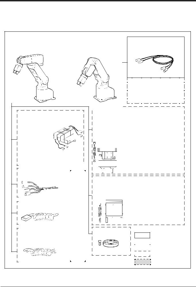
1.2.1 Robot arm
The list of structural equipment is shown in Fig. 1-1.
Vertical six-axis |
|
Vertical five-axis |
||||||||||||
RV-1A:General environment |
|
multiple-jointed type |
||||||||||||
RV-1AC-SB:Clean specification |
|
RV-2AJ:General environment |
||||||||||||
|
|
RV-2AJC-SB:Clean specification |
||||||||||||
|
or |
|
|
|||||||||||
|
|
|
|
|
|
|
|
|
|
|
|
|
|
|
|
|
|
|
|
|
|
|
|
|
|
|
|
|
|
|
|
|
|
|
|
|
|
|
|
|
|
|
|
|
Machine cable fixed type 5m |
1A-5CBL-1 |
Machine cable |
Fixed type:1A- □□ CBL-1 |
Flexed type:1A- □□ LCBL-1 |
Note) □□ refer the length.
Refer to section "1.4" for datails.
Solenoid valve set <sink type>
1 set: 1E-VD01
2 set: 1E-VD02
<source type>
1 set: 1E-VD01E2 set: 1E-VD02E
With installation bolts.
Note) Not clean specification
|
|
|
|
|
|
|
|
|
|
|
|
|
|
|
|
|
|
|
|
|
|
|
|
|
|
|
|
|
|
|
|
|
|
|
|
|
|
|
|
|
|
|
|
|
|
|
|
|
|
|
|
|
|
|
|
|
|
|
|
|
|
|
|
|
|
|
|
|
|
|
|
|
|
|
|
|
|
|
|
|
|
Hand output cable |
|
|
|
|
|
|
|
|
|
|
|
|
|
|
|
|
|
|
|
|||||||||||||||||||||
|
|
|
|
|
|
|
|
|
|
|
|
|
|
|
|
|
|
|
||||||||||||||||||||||
|
|
|
|
|
|
|
|
|
|
|
|
|
||||||||||||||||||||||||||||
|
|
|
|
|
|
|
|
|
|
|
|
|
|
|
||||||||||||||||||||||||||
1E-GR35S |
|
|
|
|
|
|
|
|
|
|
|
|
|
|
|
|
|
|
|
|||||||||||||||||||||
|
|
|
|
|
|
|
|
|
|
|
|
|
|
|
||||||||||||||||||||||||||
|
|
|
|
|
|
|
|
|
|
|
|
|
|
|
|
|
|
|
|
|
|
|
|
|
|
|
|
|
|
parts |
|
|||||||||
|
|
|
|
|
|
|
|
|
|
|
|
|
|
|
|
|
|
|
|
|
|
|
|
|
|
|
|
|
|
|
||||||||||
|
|
|
|
|
|
|
|
|
|
|
|
|
|
|
|
|
|
|
|
|
|
|
|
|
|
|
|
|
|
|
||||||||||
|
|
|
|
|
|
|
|
|
|
|
|
|
|
|
|
|
|
|
|
|
|
|
|
|
|
|
|
|
|
manufactured |
|
|||||||||
|
|
|
|
|
|
|
|
|
|
|
|
|
|
|
|
|
|
|
|
|
|
|
|
|
|
|
|
|
|
|
||||||||||
|
|
|
|
|
|
|
|
|
|
|
|
|
|
|
|
|
|
|
|
|
|
|
|
|
|
|
|
|
|
|
||||||||||
|
|
|
|
|
|
|
|
|
|
|
|
|
|
|
|
|
|
|
|
|
|
|
|
|
|
|
|
|
|
|
||||||||||
|
|
|
|
|
|
|
|
|
|
|
|
|
|
|
|
|
|
|
|
|
|
|
|
|
|
|
|
|
|
|
||||||||||
|
|
|
|
|
|
|
|
|
|
|
|
|
|
|
|
|
|
|
|
|
|
|
|
|
|
|
|
|
|
|
||||||||||
|
|
|
|
|
|
|
|
|
|
|
|
|
|
|
|
|
|
|
|
|
|
|
|
|
|
|
|
|
|
|
||||||||||
1A-HC20 |
|
|
|
|
||||||||||||||||||||||||||||||||||||
Hand input cable |
|
|
|
|
|
|
|
|
|
|
|
|
|
|
|
|
|
|
|
|||||||||||||||||||||
|
|
|
|
|
|
|
|
|
|
|
|
|
|
|
|
|
|
|
|
|
|
|
|
|
|
|
|
|
|
|
|
|
|
|
|
|||||
|
|
|
|
|
|
|
|
|
|
|
|
|
|
|
|
|
|
|
|
|
|
|
|
|
|
|
|
|
|
customer- |
|
|||||||||
|
|
|
|
|
|
|
|
|
|
|
|
|
|
|
|
|
|
|
|
|
|
|
|
|
|
|
|
|
|
|
||||||||||
|
|
|
|
|
|
|
|
|
|
|
|
|
|
|
|
|
|
|
|
|
|
|
|
|
|
|
|
|
|
|
||||||||||
|
|
|
|
|
|
|
|
|
|
|
|
|
|
|
|
|
|
|
|
|
|
|
|
|
|
|
|
|
|
|
||||||||||
|
|
|
|
|
|
|
|
|
|
|
|
|
|
|
|
|
|
|
|
|
|
|
|
|
|
|
|
|
|
|
||||||||||
|
|
|
|
|
|
|
|
|
|
|
|
|
|
|
|
|
|
|
|
|
|
|
|
|
|
|
|
|
|
|
||||||||||
|
|
|
|
|
|
|
|
|
|
|
|
|
|
|
|
|
|
|
|
|
|
|
|
|
|
|
|
|
|
|
||||||||||
|
|
|
|
|
|
|
|
|
|
|
|
|
|
|
|
|
|
|
|
|
|
|
|
|
|
|
|
|
|
|
||||||||||
Hand curl tube |
|
|
|
|
|
|
|
|
hand |
|
||||||||||||||||||||||||||||||
|
|
|
|
|
|
|
|
|
|
|
|
|
|
|
|
|
|
|
||||||||||||||||||||||
|
|
|
|
|
|
|
|
|
|
|
|
|
|
|
|
|
|
|
||||||||||||||||||||||
1 set, 2pc. 1E-ST0402C |
|
|
|
|
|
|
|
|
|
|
|
|
|
|
|
|
|
|
|
|||||||||||||||||||||
|
|
|
|
|
|
|
|
|
|
|
|
|
|
|
||||||||||||||||||||||||||
2 set, 4pc. 1E-ST0404C |
|
|
|
|
|
|
|
|
Pneumatic |
|
||||||||||||||||||||||||||||||
|
|
|
|
|
|
|
|
|
|
|
|
|
|
|
|
|
|
|
||||||||||||||||||||||
|
|
|
|
|
|
|
|
|
|
|
|
|
|
|
||||||||||||||||||||||||||
|
|
|
|
|
|
|
|
|
|
|
|
|
|
|
|
|
|
|
|
|
|
|
|
|
|
|
|
|
|
|
|
|
|
|
|
|
|
|
|
|
|
|
|
|
|
|
|
|
|
|
|
|
|
|
|
|
|
|
|
|
|
|
|
|
|
|
|
|
|
|
|
|
|
|
|
|
|
|
|
|
|
|
|
|
|
|
|
|
|
|
|
|
|
|
|
|
|
|
|
|
|
|
|
|
|
|
|
|
|
|
|
|
|
|
|
|
|
|
|
|
|
|
|
|
|
|
|
|
|
|
|
|
|
|
|
|
|
|
|
|
|
|
|
|
|
|
|
|
|
|
|
|
|
|
|
|
|
|
|
|
|
|
|
|
|
|
|
|
|
|
|
|
|
|
|
|
|
|
|
|
|
|
|
|
|
|
|
|
|
|
|
|
|
|
|
|
|
|
|
|
|
|
|
|
|
|
|
|
|
|
|
|
|
|
|
|
|
|
|
|
|
|
|
|
|
|
|
|
|
|
|
|
|
|
|
|
|
|
|
|
|
|
|
|
|
|
|
|
|
|
|
|
|
|
|
|
|
|
|
|
|
|
|
|
|
|
|
|
|
|
|
|
|
|
|
|
|
|
|
|
|
|
|
|
|
|
|
|
|
|
|
|
|
|
|
|
|
|
|
|
|
|
|
|
|
|
|
|
|
|
|
|
|
|
|
|
|
|
|
|
|
|
|
|
|
|
|
|
|
|
|
|
|
|
|
|
|
|
|
|
|
|
|
|
|
|
|
|
|
|
|
|
|
|
|
|
|
|
|
|
|
|
|
|
|
|
|
|
Fig.1-1 Structural equipment (Robot arm)
Pneumatic hand set
4A-HP01(sink type)/4A-HP01E (source type)
The set consists of the following parts.
Pneumatic hand |
1A-HP01/1A-HP01E |
Solenoid valve set (1 pc.) 1E-VD01/1E-VD01E |
|
Curl cable |
1A-GHCD/1A-GHCD |
Hand curl tube |
1A-ST0402C/1A-ST0402C |
Pneumatic hand I/F |
2A-RZ365/2A-RZ375 |
Hand adapter |
1A-HA01/1A-HA01 |
With installation bolts.
Note) Not clean specification
Motorized hand set 4A-HM01 |
|
||||||
Motorized hand |
1A-HM01 |
||||||
Curl cable |
1A-GHCD |
||||||
Motorized hand I/F |
2A-RZ364 |
||||||
Hand adapter |
1A-HA01 |
||||||
|
|
|
|
|
|
|
|
|
|
|
|
|
|
|
|
|
|
|
|
|
|
|
|


 With
With installation bolts.
 Note) Not clean specification
Hand adapter1A-HA01
With installation bolts.
Caution
Standard configuration
equipment


 Special shipping


 specifications
 Option
Prepared by customer |
1-2 Contents of the structural equipment
1General configuration
1.3 Controller
The devices shown below can be installed on the controller.
Controller |
|
|
|
|
|
|
|
|
|
|
|
|
|
|
|
|
|
|
|
|
|
|
|
|
|
|
|
|
|
|
|
|
|
|
|
|
|
|
|
|
|
|
|
|
|
|
|
|
|
|
|
|
|
|
||||||||||
|
|
|
|
|
|
|
|
|
|
|
|
|
|
|
|
|
|
|
|
|
|
|
|
|
|
|
|
|
|
|
|
|
|
|
|
|
|
|
|
|
|
|
|
|
|
|
|
|
|
|
|
|
|
|||||||||||
CR1-571 |
|
|
|
|
|
|
|
|
|
|
|
|
|
|
|
|
|
|
|
|
|
|
|
|
|
|
|
|
|
|
|
|
|
|
|
|
|
|
|
|
|
|
|
|
|
|
|
|
|
|
|
|
|
|
||||||||||
|
|
Teaching pendant(T/B) |
|
|
|
|
|
Controller protection box |
||||||||||||||||||||||||||||||||||||||||||||||||||||||||
|
|
|
|
|||||||||||||||||||||||||||||||||||||||||||||||||||||||||||||
|
|
|
|
|
|
|
|
|
|
|
|
|
R28TB |
|
|
|
|
|
CR1-MB |
|||||||||||||||||||||||||||||||||||||||||||||
|
|
|
|
|
|
|
|
|
|
|
|
|
|
|
||||||||||||||||||||||||||||||||||||||||||||||||||
|
|
|
|
|
|
|
|
|
|
|
|
|
|
|
|
|
|
|
|
|
|
|
|
|
|
|
|
|
|
|
|
|
|
|
|
|
|
|
|
|
|
|
|
|
|
|
|
|
|
|
|
|
|
|
|
|
|
|
|
|
|
|
|
|
|
|
|
|
|
|
|
|
|
|
|
|
|
|
|
|
|
|
|
|
|
|
|
|
|
|
|
|
|
|
|
|
|
|
|
|
|
|
|
|
|
|
|
|
|
|
|
|
|
|
|
|
|
|
|
|
|
|
|
|
|
|
|
|
|
|
|
|
|
|
|
|
|
|
|
|
|
|
|
|
|
|
|
|
|
|
|
|
|
|
|
|
|
|
|
|
|
|
|
|
|
|
|
|
|
|
|
|
|
|
|
|
|
|
|
|
|
|
|
|
|
|
|
|
|
|
|
|
|
|
|
|
|
|
|
|
|
|
|
|
|
|
|
|
|
|
|
|
|
|
|
|
|
|
|
|
|
|
|
|
|
|
|
|
|
|
|
|
|
|
|
|
|
|
|
|
|
|
|
|
|
|
|
|
|
|
|
|
|
|
|
|
|
|
|
|
|
|
|
|
|
|
|
|
|
|
|
|
|
|
|
|
|
|
|
|
|
|
|
|
|
|
|
|
|
|
|
|
|
|
|
|
|
|
|
|
|
|
|
|
|
|
|
|
|
|
|
|
|
|
|
|
|
|
|
|
|
|
|
|
|
|
|
|
|
|
|
|
|
|
|
|
|
|
|
|
|
|
|
|
|
|
|
|
|
|
|
|
|
|
|
|
|
|
|
|
|
|
|
|
|
|
|
|
|
|
|
|
|
|
|
|
|
|
|
|
|
|
|
|
|
|
|
|
|
|
|
|
|
|
|
|
|
|
|
|
|
|
|
|
|
|
|
|
|
|
|
|
|
|
|
|
|
|
|
|
|
|
|
|
|
|
|
|
|
|
|
|
|
|
|
|
|
|
|
|
|
|
|
|
|
|
|
|
|
|
|
|
|
|
|
|
|
|
|
|
|
|
|
|
|
|
|
|
|
|
|
|
|
|
|
|
|
|
|
|
|
|
|
|
|
|
|
|
|
|
|
|
|
|
|
|
|
|
|
|
|
|
|
|
|
|
|
|
|
|
|
|
|
|
|
|
|
|
|
|
|
|
|
|
|
|
|
|
|
|
|
|
|
|
|
|
|
|
|
|
|
|
|
|
|
|
|
|
|
|
|
|
|
|
|
|
|
|
|
|
|
|
|
|
|
|
|
|
|
|
|
|
|
|
|
|
|
|
|
|
|
|
|
|
|
|
|
|
|
|
|
|
|
|
|
|
|
|
|
|
|
|
|
|
|
|
|
|
|
|
|
|
|
|
|
|
|
|
|
|
|
|
|
|
|
|
|
|
|
|
|
|
|
|
|
|
|
|
|
|
|
|
|
|
|
|
|
|
|
|
|
|
|
|
|
|
|
|
|
|
|
|
|
|
|
|
|
|
|
|
|
|
|
|
|
|
|
|
|
|
|
|
|
|
|
|
|
|
|
|
|
|
|
|
|
|
|
|
|
|
|
|
|
|
|
|
|
|
|
|
|
|
|
|
|
|
|
|
|
|
|
|
|
|
|
|
|
|
|
|
|
|
|
|
|
|
|
|
|
|
|
|
|
|
|
|
|
|
|
|
|
|
|
|
|
|
|
|
|
|
|
|
|
|
|
|
|
|
|
|
|
|
|
|
|
|
|
|
|
|
Pneumatic I/F |
|
|
|
Parallel I/O unit |
|
|
|
|
External I/O cable |
|
|
|
|
|
|
|
|
|
|
|
|
|
|
|
|
|
|
|
|
|
|
|
|
|
|
|
|
|
|
|
|||||||||||||||||||||||||||||||||||||||||
|
|
|
|
|
|
|
|
|
|
|
|
|
|
|
|
|
|
|
|
|
|
|
|
|
|
|
|
|
|
|
|
|
|
|||||||||||||||||||||||||||||||||||||||||||||||||
|
2A-RZ365 (Sink) |
|
|
|
2A-RZ361 (Sink) |
|
|
|
|
2A-CBL05(5m) |
|
|
|
|
|
|
|
|
|
|
|
|
|
|
|
|
|
|
|
|
|
|
|
|
|
|
|
|
|
|
|
|||||||||||||||||||||||||||||||||||||||||
|
|
|
|
|
|
|
|
|
|
|
|
|
|
|
|
|
|
|
|
|
|
|
|
|
|
|
|
|
|
|
|
|
|
|||||||||||||||||||||||||||||||||||||||||||||||||
|
2A-RZ375 (Source) |
|
|
|
2A-RZ371 (Source) |
|
|
|
|
2A-CBL15(15m) |
|
|
|
PLC(Programmable |
|
|||||||||||||||||||||||||||||||||||||||||||||||||||||||||||||||||||
|
|
|
|
|
|
|
|
|
|
|
|
|||||||||||||||||||||||||||||||||||||||||||||||||||||||||||||||||||||||
|
|
|
|
|
|
|
|
|
|
|
|
|
|
|
|
|
|
|
|
|
|
|
|
|
|
|
|
|
|
|
|
|
|
|
|
|
|
|
|
|
|
|
|
|
|
|
|
|
|
|
|
|
|
|
Logic Controller) |
|
||||||||||||||||||||||||||
|
|
|
|
|
|
|
|
|
|
|
|
|
|
|
|
|
|
|
|
|
|
|
|
|
|
|
|
|
|
|
|
|
|
|
|
|
|
|
|
|
|
|
|
|
|
|
|
|
|
|
|
|
|
|
|
|||||||||||||||||||||||||||
|
|
|
|
|
|
|
|
|
|
|
|
|
|
|
|
|
|
|
|
|
|
|
|
|
|
|
|
|
|
|
|
|
|
|
|
|
|
|
|
|
|
|
|
|
|
|
|
|
|
|
|
|
|
|
External device |
|
||||||||||||||||||||||||||
|
|
|
|
|
|
|
|
|
|
|
|
|
|
|
|
|
|
|
|
|
|
|
|
|
|
|
|
|
|
|
|
|
|
|
|
|
|
|
|
|
|
|
|
|
|
|
|
|
|
|
|
|
|
|
|
|||||||||||||||||||||||||||
|
|
|
|
|
|
|
|
|
|
|
|
|
|
|
|
|
|
|
|
|
|
|
|
|
|
|
|
|
|
|
|
|
|
|
|
|
|
|
|
|
|
|
|
|
|
|
|
|
|
|
|
|
|
|
|
|
|
|
|
|
|
|
|
|
|
|
|
|
|
|
|
|
|
|
|
|
|
|
|
|
|
|
|
|
|
|
|
|
|
|
|
|
|
|
|
|
|
|
|
|
|
|
|
|
|
|
|
|
|
|
|
|
|
|
|
|
|
|
|
|
|
|
|
|
|
|
|
|
|
|
|
|
|
|
|
|
|
|
|
||||||||||||||||||||||||||
|
|
|
|
|
|
|
|
|
|
|
|
|
|
|
|
|
|
|
|
|
|
|
|
|
|
|
|
|
|
|
|
|
|
|
|
|
|
|
|
|
|
|
|
|
|
|
|
|
|
|
|
|
|
|
Prepared by customer |
|
||||||||||||||||||||||||||
|
|
|
|
|
|
|
|
|
|
|
|
|
|
|
|
|
|
|
|
|
|
|
|
|
|
|
|
|
|
|
|
|
|
|
|
|
|
|
|
|
|
|
|
|
|
|
|
|
|
|
|
|
|
|
|
|||||||||||||||||||||||||||
|
|
|
|
|
|
|
|
|
|
|
|
|
|
|
|
|
|
|
|
|
|
|
|
|
|
|
|
|
|
|
|
|
|
|
|
|
|
|
|
|
|
|
|
|
|
|
|
|
|
|
|
|
|
|
|
|
|
|
|
|
|
|
|
|
|
|
|
|
|
|
|
|
|
|
|
|
|
|
|
|
|
|
|
|
|
|
|
|
|
|
|
|
|
|
|
|
|
|
|
|
|
|
|
|
|
|
|
|
|
|
|
|
|
|
|
|
|
|
|
|
|
|
|
|
|
|
|
|
|
|
|
|
|
|
|
|
|
|
|
|
|
|
|
|
|
|
|
|
|
|
|
|
|
|
|
|
|
|
|
|
|
|
|
|
|
|
|
|
|
|
|
|
|
|
|
|
|
|
|
|
|
|
|
|
|
|
|
|
|
|
|
|
|
|
|
|
|
|
|
|
|
|
|
|
|
|
|
|
|
|
|
|
|
|
|
|
|
|
|
|
|
|
|
|
|
|
|
|
|
|
|
|
|
|
|
|
|
|
|
|
|
|
|
|
|
|
|
|
|
|
|
|
|
|
|
|
|
|
|
|
|
|
|
|
|
|
|
|
|
|
|
|
|
|
|
|
|
|
|
|
|
|
|
|
|
|
|
|
|
|
|
|
|
|
|
|
|
|
|
|
|
|
|
|
|
|
|
|
|
|
|
|
|
|
|
|
|
|
|
|
|
|
|
|
|
|
|
|
|
|
|
|
|
|
|
|
|
|
|
|
|
|
|
|
|
|
|
|
|
|
|
|
|
|
|
|
|
|
|
|
|
|
|
|
|
|
|
|
|
|
|
|
|
|
|
|
|
|
|
|
|
|
|
|
|
|
|
|
|
|
|
|
|
|
|
|
|
|
|
|
|
|
|
|
|
|
|
|
|
|
|
|
|
|
|
|
|
|
|
|
|
|
|
|
|
|
|
|
|
|
|
|
|
|
|
|
|
|
|
|
|
|
|
|
|
|
|
|
|
|
|
|
|
|
|
|
|
|
|
|
|
|
|
|
|
|
|
|
|
|
|
|
|
|
|
|
|
|
|
|
|
|
|
|
|
|
|
Expansion option box |
|
|
Extended serial I/F |
|
|
CC-LINK I/F |
|
|
|
|
ETHERNET I/F |
|
Additional axis I/F |
|||||||||||||||||||||||||||||||||||||||||||||||||||||||||
|
CR1-EB3 |
|
|
2A-RZ581E |
|
|
2A-HR575E |
|
|
|
|
2A-HR533E |
|
2A-RZ541E |
|||||||||||||||||||||||||||||||||||||||||||||||||||||||||
|
|
|
|
|
|
|
|
|
|
||||||||||||||||||||||||||||||||||||||||||||||||||||||||||||||
|
|
|
|
|
|
|
|
|
|
|
|
|
|
|
|
|
|
|
|
|
|
|
|
|
|
|
|
|
|
|
|
|
|
|
|
|
|
|
|
|
|
|
|
|
|
|
|
|
|
|
|
|
|
|
|
|
|
|
|
|
|
|
|
|
|
|
|
|
|
|
|
|
|
|
|
|
|
|
|
|
|
|
|
|
|
|
|
|
|
|
|
|
|
|
|
|
|
|
|
|
|
|
|
|
|
|
|
|
|
|
|
|
|
|
|
|
|
|
|
|
|
|
|
|
|
|
|
|
|
|
|
|
|
|
|
|
|
|
|
|
|
|
|
|
|
|
|
|
|
|
|
|
|
|
|
|
|
|
|
|
|
|
|
|
|
|
|
|
|
|
|
|
|
|
|
|
|
|
|
|
|
|
|
|
|
|
|
|
|
|
|
|
|
|
|
|
|
|
|
|
|
|
|
|
|
|
|
|
|
|
|
|
|
|
|
|
|
|
|
|
|
|
|
|
|
|
|
|
|
|
|
|
|
|
|
|
|
|
|
|
|
|
|
|
|
|
|
|
|
|
|
|
|
|
|
|
|
|
|
|
|
|
|
|
|
|
|
|
|
|
|
|
|
|
|
|
|
|
|
|
|
|
|
|
|
|
|
|
|
|
|
|
|
|
|
|
|
|
|
|
|
|
|
|
|
|
|
|
|
|
|
|
|
|
|
|
|
|
|
|
|
|
|
|
|
|
|
|
|
|
|
|
|
|
|
|
|
|
|
|
|
|
|
|
|
|
|
|
|
|
|
|
|
|
|
|
|
|
|
|
|
|
|
|
|
|
|
|
|
|
|
|
|
|
|
|
|
|
|
|
|
|
|
|
|
|
|
|
|
|
|
|
|
|
|
|
|
|
|
|
|
|
|
|
|
|
|
|
|
|
|
|
|
|
|
|
|
|
|
|
|
|
|
|
|
|
|
|
|
|
|
|
|
|
|
|
|
|
|
|
|
|
|
|
|
|
|
|
|
|
|
|
|
|
|
|
|
|
|
|
|
|
|
|
|
|
|
|
|
|
|
|
|
|
|
|
|
|
|
|
|
|
|
|
|
|
|
|
|
|
|
|
|
|
|
|
|
|
|
|
|
|
|
|
|
|
|
|
|
|
|
|
|
|
|
|
|
|
|
|
|
|
|
|
|
|
|
|
|
|
|
|
|
|
|
|
|
|
|
|
|
|
|
|
|
|
|
|
|
|
|
|
|
|
|
|
|
|
|
|
|
|
|
|
|
|
|
|
|
|
|
|
|
|
|
|
|
|
|
|
|
|
|
|
|
|
|
|
|
|
|
|
|
|
|
|
|
|
|
|
|
|
|
|
|
|
|
|
|
|
|
|
|
|
|
|
|
|
|
|
|
|
|
|
|
|
|
|
|
|
|
|
|
|
|
|
|
|
|
|
|
|
|
|
|
|
|
|
|
|
|
|
|
|
|
|
|
|
|
|
|
|
|
|
|
|
|
|
|
|
|
|
|
|
|
|
|
|
|
|
|
|
|
|
|
|
|
|
|
|
|
|
|
|
|
|
|
|
|
|
|
|
|
|
|
|
|
|
|
|
|
|
|
|
|
|
|
|
|
|
|
|
|
|
|
|
|
|
|
|
|
|
|
|
|
|
|
|
|
|
|
|
|
|
|
|
|
|
|
|
|
|
|
|
|
|
|
|
|
|
|
|
|
|
|
|
|
|
|
|
|
|
|
|
|
|
|
|
|
|
|
|
|
|
|
|
|
|
|
|
|
|
|
|
|
|
|
|
|
|
|
|
|
|
|
|
|
|
|
|
|
|
|
|
|
|
|
|
|
|
|
|
|
|
|
|
|
|
|
|
|
|
|
|
|
|
|
|
|
|
|
|
|
|
|
|
|
|
|
|
|
|
|
|
|
|
|
|
|
|
|
|
|
|
|
|
|
|
|
|
|
|
|
|
|
|
|
|
|
|
|
|
|
|
|
|
|
|
|
|
|
|
|
|
|
|
|
|
|
|
|
|
|
|
|
|
|
|
|
|
|
|
|
|
|
|
|
|
|
|
|
|
|
|
|
|
|
|
|
|
|
|
|
|
|
|
|
|
|
|
|
|
|
|
|
|
|
|
|
|
|
|
|
|
|
|
|
|
|
|
|
|
|
|
|
|
|
|
|
|
|
|
|
|
|
|
|
|
|
|
|
|
|
|
|
|
|
|
|
|
|
|
|
|
|
|
|
|
|
|
|
|
|
|
|
|
|
|
Personal computer |
|
Personal computer |
||||||||||||||||||||||||||||||||||||||
|
|
||||||||||||||||||||||||||||||||||||||||
|
|
cable |
|
Prepared |
|||||||||||||||||||||||||||||||||||||
|
|
|
|||||||||||||||||||||||||||||||||||||||
|
RS-MAXY-CBL |
|
by customer |
||||||||||||||||||||||||||||||||||||||
|
|
||||||||||||||||||||||||||||||||||||||||
|
RS-AT-RCBL |
|
|
|
|
|
|
|
|
|
|
|
|
|
|
|
|
|
|
|
|
|
|
|
|
|
|
||||||||||||||
|
|
|
|
|
|
|
|
|
|
|
|
|
|
|
|
|
|
|
|
|
|
|
|
|
|
|
|
|
|
|
|
|
|
|
|
|
|
|
|
|
|
|
|
|
|
|
|
|
|
|
|
|
|
|
|
|
|
|
|
|
|
|
|
|
|
|
|
|
|
|
|
|
|
|
|
|
|
|
|
|
|
|
|
|
|
|
|
|
|
|
|
|
|
|
|
|
|
|
|
|
|
|
|
|
|
|
|
|
|
|
|
|
|
|
|
|
|
|
|
|
|
|
|
|
|
|
|
|
|
|
|
|
|
|
|
|
|
|
|
|
|
|
|
|
|
|
|
|
|
|
|
|
|
|
|
|
|
|
|
|
|
|
|
|
|
|
|
|
|
|
|
|
|
|
|
|
|
|
|
|
|
|
|
|
|
|
|
|
|
|
|
|
|
|
|
|
|
|
|
|
|
|
|
|
|
|
|
|
|
|
|
|
|
|
|
|
|
|
|
|
|
|
|
|
|
|
|
|
|
|
|
|
|
|
|
|
|
|
|
|
|
|
|
|
|
|
|
|
|
|
|
|
|
|
|
|
|
|
|
|
|
|
|
|
|
|
|
|
|
|
|
|
|
|
|
|
|
|
|
|
|
|
|
|
|
|
|
|
|
|
|
|
|
|
|
|
|
|
|
|
|
|
|
|
|
|
|
|
|
|
|
|
|
|
|
|
|
|
|
|
|
|
|
|
|
|
|
|
|
|
|
|
|
|
|
|
|
|
|
|
|
|
|
|
|
|
|
|
|
|
|
|
|
|
|
|
|
|
|
|
|
|
|
|
|
|
|
|
|
|
|
|
|
|
|
|
|
|
|
|
|
|
|
|
|
|
|
|
|
|
|
|
|
|
|
|
|
|
|
|
|
|
|
|
|
|
|
|
|
|
|
|
|
|
|
|
|
|
|
|
|
|
|
|
|
|
|
|
|
|
|
|
|
|
|
|
|
|
|
|
|
|
|
|
|
|
|
|
|
|
|
|
|
|
|
|
|
|
|
|
|
 Personal computer support software
(MS-Windows95/98/NT4.0)
3A-01C-WINE(CD-ROM)
Personal computer support software mini
(MS-Windows95/98/NT4.0)3A-02C-WINE(CD-ROM)
Caution
Standard configuration equipment


 Special shipping


 specifications
 Option
Prepared by customer |
Fig.1-2 Structural equipment(Controller)
Controller 1-3

1General configuration
1.4 Contents of the Option equipment and special specification
A list of all Optional equipments and special specifications are shown below. Table 1-1 The list of Option equipment and special specification
Item |
Type |
Specifications |
Classific |
Descripsion |
|
ation |
|||||
|
|
|
|
||
|
|
|
|
|
|
|
|
|
|
|
|
Extended machine cables |
1A-10CBL-1 |
For fixing |
□ |
10 |
|
|
|
|
|
||
|
1A-15CBL-1 |
(Two sets for power and signal) |
□ |
15 |
|
|
|
||||
|
|
|
|
|
|
|
1A-05LCBL-1 |
|
□ |
5m |
|
|
|
For flexed |
|
|
|
|
1A-10LCBL-1 |
□ |
10 |
||
|
(Two sets for power and signal) |
||||
|
|
|
|
||
|
1A-15LCBL-1 |
|
□ |
15 |
|
|
|
|
|
|
|
Pneumatic hand set |
4A-HP01 |
Pneumatic hand, Solenoid valve set |
○ |
The pneumatic hand and required parts are pre- |
|
|
|
(1 pc.), Curl tube(1 pc.), Pneumatic |
pared in a set.(sink type) |
||
|
|
|
|
||
|
4A-HP01E |
hand I/F, Hand adapter, Installation |
○ |
The pneumatic hand and required parts are pre- |
|
|
bolts |
||||
|
|
|
|
pared in a set.(source type) |
|
Motorized hand set |
4A-HM01 |
Motorized hand, Hand curl cable, |
|
The motorized hand and required parts are pre- |
|
Motorized hand I/F, Hand adapter, |
○ |
||||
|
|
||||
|
|
Installation bolts |
|
pared in a set. |
|
Solenoid valve set |
1E-VD01 |
1 set(Sink type) |
○ |
A solenoid valve set for the pneumatic hand. |
|
|
|
|
|
|
|
|
1E-VD02 |
2 set(Sink type) |
○ |
|
|
|
|
|
|
|
|
|
1E-VD01E |
1 set(Source type) |
○ |
|
|
|
|
|
|
|
|
|
1E-VD02E |
2 set(Source type) |
○ |
|
|
|
|
|
|
|
|
Hand output cable |
1E-GR35S |
Length 350mm with robot side con- |
○ |
The cable is connected to the hand output con- |
|
|
|
nector. One terminal is not treated. |
|
nector by the customer. |
|
Hand input cable |
1A-HC20 |
Length 200mm with robot side con- |
○ |
The cable is connected to the sensor by the cus- |
|
|
|
nector. One terminal is not treated. |
|
tomer. |
|
Hand curl tube |
1E-ST0402C |
For solenoid valve 1set.:Φ4x2 |
○ |
|
|
|
|
|
|
Curl type air tube |
|
|
1E-ST0404C |
For solenoid valve 2set.:Φ4x4 |
○ |
||
|
|
|
|
|
|
Hand adapter |
1A-HA01 |
|
○ |
For RV-M1 hand installation flange conversion. |
|
Teaching pendant |
R28TB |
Cable length 7m |
○ |
With 3-position deadman switch/ IP 65 |
|
|
|
|
|
|
|
Pneumatic hand interface |
2A-RZ365 |
DO: 8 point (Sink type) *1) |
○ |
It is necessary when the hand output signal of the |
|
|
|
|
|
robot arm is used. (Integrated in the controller.) |
|
|
|
|
|
||
|
2A-RZ375 |
DO: 8 point (Source type) *1) |
○ |
*1)In RV-1A/2AJ type, even four points are |
|
|
|
|
|
effective. |
|
Parallel I/O interface |
2A-RZ361 |
DO: 32 point (Sink type)/ |
○ |
The unit for expansion the external input/output. |
|
|
|
DI : 32 point (Sink type) |
|
Electrical isolated Type |
|
|
|
|
|
(100mA/Point) |
|
|
2A-RZ371 |
DO: 32 point (Source type)/ |
○ |
||
|
|
||||
|
DI : 32 point (Source type) |
|
|||
|
|
|
|
||
|
|
|
|
|
|
External I/O cable |
2A-CBL05 |
5m |
○ |
Use to connect the external peripheral device to |
|
|
|
|
|
the parallel input/output unit |
|
|
2A-CBL15 |
15m |
○ |
||
|
|
|
|
|
|
Personal computer cable |
RS-MAXY-CBL |
RS-232C cable 3m for PC-AT com- |
○ |
Use RS-AT-RCBL for the connection from the |
|
|
|
patible model |
|
expansion option box. |
|
|
RS-AT-RCBL |
|
○ |
|
|
|
|
|
|
|
|
Personal computer |
3A-01C-WINE |
CD-ROM |
○ |
MS-Windows95/98/NT4.0 |
|
Support software |
(With the simulation function) |
||||
|
|
|
|
|
|
Personal computer |
3A-02C-WINE |
CD-ROM |
○ |
MS-Windows95/98/NT4.0 |
|
Support software mini |
(Without the simulation function) |
||||
|
|
|
|
|
|
Expansion option box |
CR1-EB3 |
Up to three option cards can be |
○ |
Install on the side of the controller |
|
|
|
mounted |
|||
|
|
|
|
||
|
|
|
|
|
|
Extended serial interface |
2A-RZ581E |
RS-232C x 1 |
○ |
CR-EB3 is need. |
|
|
|
RS-232C or RS-422 x 1 |
|
|
|
CC-Link interface |
2A-HR575E |
Local station (The local station |
○ |
for MELSEC PLC with CC-Link connection. CR- |
|
|
|
alone is supported.) |
EB3 is need. |
||
|
|
|
|
|
|
ETHERNET interface |
2A-HR533E |
ETHERNET x 1 |
○ |
CR-EB3 is need. |
|
|
|
|
|
|
|
Additional axis interface |
2A-RZ541E |
SSC x 1 |
○ |
MR-J2 servoAmplifer Unit connection. CR-EB3 is |
|
|
|
Up to 8 axises can be added |
need. |
||
|
|
|
|
|
|
|
|
|
|
The controller protection box is used to protect |
|
Controller protection box |
CR1-MB |
IP54 |
□ |
the controller from an oil mist or other operating |
|
|
|
|
|
environment. Note2) |
Note1) In the classification column, ○ refers to an option,and □ to a Sipping special specifications.
Note2) Use this option to protect the controller from the oil mist when the controller will be installed in the environ- ment such as the oil mist.
1-4 Contents of the Option equipment and special specification

2Robot arm
2 Robot arm
2.1 Standard specifications
2.1.1 Standard specifications
Table 2-1 Tab Standard specifications of robot
|
Item |
Unit |
|
|
Specifications |
|
|
|
||
|
|
|
|
|
|
|
|
|
|
|
|
|
|
|
|
|
|
|
|
|
|
Type |
|
|
|
RV-1A |
|
RV-1AC-SB |
RV-2AJ |
|
RV-2AJC-SB |
|
|
|
|
|
|
|
|
|
|
||
Degree of freedom |
|
|
6 |
|
5 |
|
||||
|
|
|
|
|
|
|
|
|
||
Installation posture |
|
On floor, hanging |
|
On floor |
On floor, hanging |
|
On floor |
|||
|
|
|
|
|
|
|
|
|
|
|
Structure |
|
|
|
|
|
Vertical, multiple-joint type |
|
|
|
|
|
|
|
|
|
|
|
||||
Drive system |
|
|
|
ACservo motor (J1 toJ3:50W with brake, |
J4,J6:15W no brake, |
J5:15Wwith brake) |
||||
|
|
|
|
|
|
|
|
|||
Position detection method |
|
|
|
Absolute encoder |
|
|
|
|||
|
|
|
|
|
|
|
|
|
|
|
|
|
Shoulder shift |
|
|
0 |
|
|
|
||
|
|
|
|
|
|
|
|
|
||
|
|
Upper arm |
|
|
250 |
|
|
|
||
|
|
|
|
|
|
|
|
|
||
Arm length |
|
Fore arm |
|
|
160 |
|
|
|
||
|
|
|
|
|
|
|
|
|
|
|
|
|
Elbow shift |
|
|
90 |
|
0 |
|
||
|
|
|
|
|
|
|
|
|
|
|
|
|
Wrist length |
|
|
72 |
|
|
|
||
|
|
|
|
|
|
|
|
|
|
|
|
|
J1 |
|
|
|
300(-150 to +150) |
|
|
|
|
|
|
|
|
|
|
|
|
|
|
|
|
|
J2 |
|
|
|
180(-60 to +120) |
|
|
|
|
|
|
|
|
|
|
|
|
|||
Operating |
|
J3 |
Degree |
95(+60 to +155) |
230(-110 to +120) |
|||||
range |
|
|
|
|
|
|
|
|
|
|
|
J4 |
320(-160 to +160) |
|
|
||||||
|
|
|
||||||||
|
|
|
|
|
|
|
|
|
|
|
|
|
J5 |
|
|
|
180(-90 to +90) |
|
|
|
|
|
|
|
|
|
|
|
|
|
|
|
|
|
J6 |
|
|
|
400(-200 to +200) |
|
|
|
|
|
|
|
|
|
|
|
|
|
||
|
|
J1 |
|
|
180 |
|
|
|
||
|
|
|
|
|
|
|
|
|
||
|
|
J2 |
|
|
90 |
|
|
|
||
|
|
|
|
|
|
|
|
|
||
Speed of |
|
J3 |
Degree/ |
|
135 |
|
|
|
||
motion |
|
|
s |
|
|
|
|
|
|
|
|
J4 |
|
180 |
|
|
|||||
|
|
|
|
|
|
|
|
|
|
|
|
|
J5 |
|
|
180 |
|
|
|
||
|
|
|
|
|
|
|
|
|
||
|
|
J6 |
|
|
210 |
|
|
|
||
|
|
|
|
|
|
|
|
|||
Maximum resultant velocity |
mm/s |
Approx. 2200 |
Approx. 2100 |
|||||||
|
|
|
|
|
|
|
|
|
|
|
Load |
|
MaximumNote1) |
kg |
|
1.5 |
|
2 |
|
||
|
Rating |
|
1 |
|
1.5 |
|
||||
|
|
|
|
|
|
|||||
|
|
|
|
|
|
|
|
|
|
|
Pose repeatability Note2) |
|
|
± 0.02 |
|
|
|
||||
Ambient temperature |
|
|
|
0 to 40 |
|
|
|
|||
|
|
|
|
|
|
|
|
|||
Mass |
|
|
kg |
Approx. 19 |
Approx. 17 |
|||||
|
|
|
|
|
|
|
|
|
|
|
Allowable |
|
J4 |
|
|
1.44 |
|
|
|||
|
|
N m |
|
|
|
|
|
|
|
|
|
J5 |
|
1.44 |
|
2.16 |
|
||||
moment load |
|
|
|
|
||||||
|
|
|
|
|
|
|
|
|
|
|
|
J6 |
|
|
0.73 |
|
1.10 |
|
|||
|
|
|
|
|
|
|||||
|
|
|
|
|
|
|
||||
Allowable |
|
J4 |
|
2.16x10⁻² |
|
|
||||
|
J5 |
kg 2 |
2.16x10⁻² |
3.24x10⁻² |
||||||
inertia |
|
|||||||||
|
J6 |
|
5.62x10⁻³ |
8.43x10⁻³ |
||||||
|
|
|
||||||||
Arm reachable radius |
mm |
|
418 |
|
410 |
|
||||
(front p-axis center point) |
|
|
|
|||||||
|
|
|
|
|
|
|
|
|||
|
|
|
|
|
|
|
|
|||
Tool wiring Note3) |
|
Four input signals (Hand section), |
Four output signals (Base section), |
|||||||
|
|
|
Motorized hand output (Hand section) |
|
|
|
||||
|
|
|
|
|
|
|
|
|
||
|
|
|
|
|
|
|
|
|
|
|
Tool pneumatic pipes |
|
Φ4x4 (Base to hand |
|
Φ4x3 (Base to hand |
Φ4x4 (Base to hand |
|
Φ4x3 (Base to hand |
|||
|
section) |
|
section) |
section) |
|
section) |
||||
|
|
|
|
|
|
|||||
|
|
|
|
|
|
|
|
|
||
Supply pressure |
MPa |
|
0.5 ± 10% |
|
|
|
||||
|
|
|
|
|
|
|
|
|
||
Protection specificationNote4) |
|
IP30 |
|
|
IP30 |
|
|
|||
Degree of cleanlinessNote5) |
|
|
|
100(0.3μm) |
|
|
100(0.3μm) |
|||
Paint color |
|
|
|
|
|
Light gray (Equivalent to Munsell: 7.65Y7.6/0.73) |
||||
|
|
|
|
|
|
|
|
|
|
|
Note1)The maximum load capacity is the mass with the flange posture facing downword at the ± 10 degree limit.
Note2)The pose repeatability details are given in Page 6, "2.2.1 Pose repeatability and distance accuracy" Note3)When using the 4-point hand output, the pneumatic hand interface (option) is required.
Note4)The protection specification details are given in Page 8, "2.2.3 Protection specifications and working environment" .
Note5)The down flow (0.3m/s or more) in the clean room and the internal suction by using attached vacuum generating valve are necessary conditions for the cleanliness.
Standard specifications 2-5
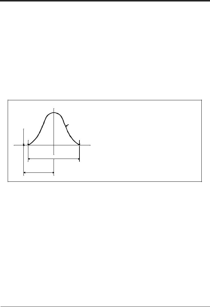
2 Robot arm
2.2 Definition of specifications
The accuracy of pose repeatability mentioned in catalogs and in the specification manual is defined as follows.
2.2.1 Pose repeatability and distance accuracy
This robot, the pose repeatability and distance accuracy are defined and calculated in Table 2-2.
(1) The pose accuracy in terms of coordinates (XYZ) for the standard point which is obtained repeatedly under the same conditions and motions when the robot is on an operating course.
(2) The standard point is the intersection between the J6 axis and the flange surface for tooling installation.
Table 2-2 Specified accuracy
Item |
Specified conditionds |
|
|
|
|
Pose repeatability |
The value equal to the average of the maximum value and the minimum value of the group of |
|
attained poses, with (+) or (-) added. |
|
|
Distance accuracy |
The distance from the teaching point to the point that is equal to the average of the maximum |
|
value and the minimum value of the group of attained poses. |
|
|
|
Group of attained poses |
Programmed pose |
(X, Y, Z) |
Min. |
Max. |
Measuring conditions |
|
|
|
|
Load ................................................................ |
A load equal to the rated |
|
|
|
|
load at the mass capacity |
|
Double of |
pose repeatability |
|
reference point |
|
The number of repitition and speed |
100 times at 100% speed |
|||
|
|
|||
Distance |
|
Measuring instrument .............................. |
Non-contact displace- |
|
|
|
ment meter |
||
accuracy |
|
|
||
|
|
|
Fig.2-1 Specified accuracy
[Caution] The pose accuracy given in the specifications is the accuracy measured under the same conditions. It does not include the effect of the robot working environment or conditions. Thus, even when used on the same path, the repeatability according to the presence of a workpiece, or the repeatability when the temperature changes will cause arm slack or expansion, so the accuracy will drop slightly. This also applies to when the teaching speed and actual speed are different or when the coordinates set with val- ues.
2-6 Definition of specifications
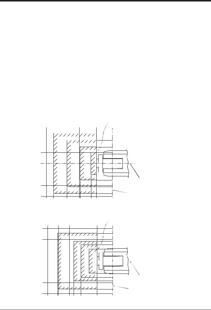
Robot arm
2.2.2 Rated load (mass capacity)
The robot's mass capacity is expressed solely in terms of mass, but even for tools and works of similar mass, eccentric loads will have some restrictions. When designing the tooling or when selecting a robot, consider the fol- lowing issues.
(1) The tooling should have the value less or equal than the smaller of the tolerable inertia and the tolerable moment found in Page 5, "Table 2-1 Tab Standard specifications of robot".
(2)Fig. 2-2 and Fig. 2-3shows the distribution dimensions for the center of gravity in the case where the vol- ume of the load is relatively small. Use this figure as a reference when designing the tooling.
(3)When the load is not mass, but force, you should design the tooling so that it does not exceed the value for allowable moment described in Page 5, "Table 2-1 Tab Standard specifications of robot".
[Caution] The mass capacity is greatly influenced by the operating speed of the robot and the motion posture. Even if you are within the allowable range mentioned previously, an overload or generate an overcurrnt alarm could occur. In such cases, it will be necessary to change the time setting for acceleration/decel- eration, the operating speed, and the motion posture.
[Caution] The overhang amount of the load for the specified moment and inertia in this section is the dynamic limit value determined by the motor driving each axis and by the capacity of the reduction gears. Conse- quently, accuracy cannot be guaranteed for the entire tooling area. Since accuracy is based on the cen- ter point of the mechanical interface surface, position accuracy can diminish as you go away from the flange surface, or vibration can result, with tooling that is not rigid or that is long.
Maximum load capacity
with the flange posture facing downword
 150
150 
 136
136
|
|
0.3kg |
|
|
|
106 |
|
|
|
|
|
|
|
|
|
|
|
|
0.5kg |
|
|
100 |
|
|
|
|
|
|
75 |
|
|
|
|
|
1.0kg |
|
|
||
|
|
|
|
50 |
|
||
|
|
|
|
|
|
|
|
|
|
|
|
|
1.5 |
|
|
|
|
|
|
|
kg |
|
|
300 |
250 |
200 |
150 |
100 |
72 |
0 |
|
|
|
|
|
|
|
50 |
|
|
|
|
|
|
|
75 |
Rotation center for J6 axis |
|
|
|
|
|
|
|
|
|
|
|
|
|
|
100 |
|
|
|
|
|
|
|
106 |
|
|
|
|
|
|
|
136 |
Rotation center for J5 axis |
|
|
|
|
|
|
150 |
|
|
268 |
207 |
147 |
97 |
|
|
|
Fig.2-2 Position of center of gravity for loads (for loads with comparatively small volume) RV-1A/1AC-SB
Maximum load capacity
with the flange posture facing downword
|
|
|
|
|
|
150 |
|
|
|
|
|
|
|
129 |
|
|
|
0.5kg |
|
|
|
100 |
|
|
|
|
1.0kg |
|
|
91 |
|
|
|
|
|
|
75 |
|
|
|
|
|
|
1.5kg |
|
|
|
|
|
|
|
|
56 |
|
|
|
|
|
|
|
2kg |
|
|
|
|
|
|
|
|
|
|
300 |
250 |
200 |
150 |
100 |
72 |
0 |
|
|
|
|
|
|
|
56 |
|
|
|
|
|
|
|
75 |
Rotation center for J6 axis |
|
|
|
|
|
|
|
|
|
|
|
|
|
|
91 |
|
|
|
|
|
|
|
100 |
|
|
|
|
|
|
|
129 |
Rotation center for J5 axis |
|
|
|
|
|
|
|
|
|
|
|
|
|
|
150 |
|
254 180 147 110
Fig.2-3 Position of center of gravity for loads (for loads with comparatively small volume) RV-2AJ/2AJC-SB
Definition of specifications 2-7

Robot arm
2.2.3Protection specifications and working environment (1) Types of protection specifications
The robot arm has protection specifications that comply with the IEC Standards. The protection specifications and applicable fields are shown in Table 2-3.
Table 2-3 Protection specifications and applicable fields
Protection |
IEC Standards |
Applicable field |
Remarks |
|
specifications |
value |
|||
|
|
|||
|
|
|
|
|
|
|
|
|
|
General-purpose envi- |
IP30 |
General assembly |
|
|
ronment specifications |
|
Slightly dusty environment |
|
|
|
|
|
|

 CAUTION Use the controller protection box (CR1-MB) optional to protect the controller from
  the environment when the controller will be used in the environment such as the oil mist shown in the Table 2-3. Refer to the section Page 59, "(3) Controller protection box" for details on the controller protection box.
InformationThe IEC IP30
IP30 refers to a protective structure with which the tip of a solid object, such as a tool or wire, having a diameter or thickness exceeding 2.5mm cannot enter. No particular protection is provided against the entry of water.
The warranty is invalid for any faults that occur when the robot is used under the following conditions. 1) In surroundings that generate inflammable gases or corrosive gasses.
2)In surroundings where water, oil, and chips fall directly on the robot.
3)Mist atmosphere exceeding the specification.
2-8 Definition of specifications

Robot arm
2.2.4 Clean specifications
(1) Types of clean specifications
The clean specifications of robot arm shown in Table 2-4.
Please confirm the delivery date, because both are special specifications. Table 2-4 Clean specifications
Clean |
Type |
Degree of |
Internal suction |
Remarks |
|
specifications |
cleanliness |
||||
|
|
|
|||
|
|
|
|
|
|
|
|
|
|
|
|
Type SB |
RV-1AC-SB |
100(0.3μm) |
Internal suction with vaccum generating valve. |
A vacuum generating |
|
|
RV-2AJC-SB |
|
|
valve (refer to Table 2- |
|
|
|
|
|
5) is enclosed. |
|
|
|
|
|
|
Table 2-5 Specifications of vacuum generation valve
Type |
Maker |
Air pressure |
|
|
|
|
|
|
MEDT 10 |
Koganei |
0.2 to 0.6 MPa |
|
|
|
■ Precautions for use
1) When using a device that moves or rotates the robot arm, the down flow may not be secured because of the air flow. In this case, the degree of cleanliness cannot be ensured.
2)In the case of clean specification robot, the base side hoses are four and fore arm side hoses are three. Prepare the hose of Φ4 x 2.5 and connect this joint to the appended vacuum generating valve or the vac- uum pump prepared by the customer.
*If the appended vacuum generating valve is used, connect the rear joint of the robot to the joint on the "VACUUM" side of the vacuum generating valve. Moreover, in order to prevent the exhaust of the vacuum generating valve from impairing the cleanness, install the vacuum generating valve on the downstream side of the down flow or attach the filter to the exhaust section as possible.
Recommended filter: Exhaust filter EF300-02, Koganei Corporation
*If any vacuum pump is prepared by the customer, assure on the vacuum side flow rate 50 liters/min.(ANR) or more .
Definition of specifications 2-9
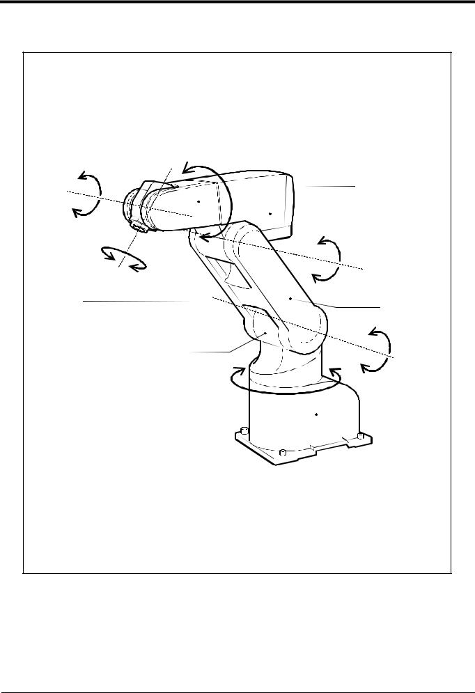
Robot arm
2.3 Names of each part of the robot
Fore arm |
|
|
|
|
|
|
|
|
|
|
|
J5-axis |
Note) |
Elbow block |
|
|
|
||
J4-axis |
|
|
|
|
|
|
|
|
|
|
|
|
|
|
|
|
|
|
|
J6-axis |
|
J3-axis |
|
|
|
||
|
|
|
|
Mechanical interface |
|
Upper arm |
|
(Hand installation flange surface) |
|
|
|
|
|
|
|
|
|
|
|
Shoulder |
|
|
|
|
|
|
J2-axis |
J1-axis
Base
Note)J4-axis dosen't exist for 5-axis type.
Fig.2-4 Names of each part of the robot
2-10 Names of each part of the robot
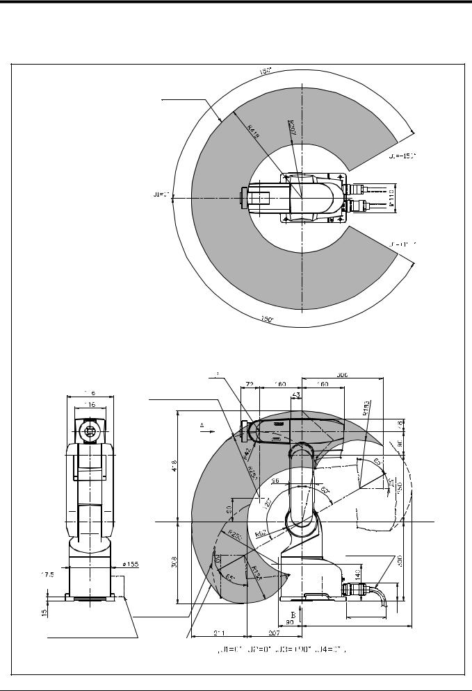
Robot arm
2.4 Outside dimensions Operating range diagram
(1) RV-1A/1AC-SB
point path
Operating range at section of X-X
Flange downward limit line(dotted line)
X
 (Front)
Flange downward singular point path
Solenoid valve (optional) |
|
installation position |
point path |
X
Machine cable (Connect to the controller)
150 or more |
Approx. 70 |
|


 (Back projects)


 pose
pose
Note 1) Refer to Fig. 2-7 for the hand installation flange section and installation base section dimensions.
Fig.2-5 Outside dimensions for RV-1A/1AC-SB
Outside dimensions Operating range diagram 2-11

Robot arm
(2)RV-2AJ/2AJC-SB
point path
Operating range at section of X-X
Flange downward |
P |
|
|
|
|
|
|
||||||||||||||||||||||||||||||||||||||||||||||||||||||||
limit line(dotted line) |
|
|
|
|
|
|
|||||||||||||||||||||||||||||||||||||||||||||||||||||||||
|
|
|
|
|
|
|
|
|
|
|
|
|
|
|
|
|
|
|
|
|
|
|
|
|
|
|
|
|
|
|
|
|
|
|
|
|
|
|
|
|
|
|
|
|
|
|
|
|
|
|
|
|
|
|
|
|
|
|
|
|
|||
|
|
|
|
|
|
|
|
|
|
|
|
|
|
|
|
|
|
|
|
|
|
|
|
|
|
|
|
|
|
|
|
|
|
|
|
|
|
|
|
|
|
|
|
|
|
|
|
|
|
|
|
|
|
|
|
|
|
|
|
|
|
|
|
|
|
|
|
|
|
|
|
|
|
|
|
|
|
|
|
|
|
|
|
|
|
|
|
|
|
|
|
|
|
|
|
|
|
|
|
|
|
|
|
|
|
|
|
|
|
|
|
|
|
|
|
|
|
|
|
|
|
|
|
|
|
|
|
|
|
|
|
|
|
|
|
|
|
|
|
|
|
|
|
|
|
|
|
|
|
|
|
|
|
|
|
|
|
|
|
|
|
|
|
|
|
|
|
|
|
|
|
|
|
|
|
|
|
|
|
|
|
|
|
|
|
|
|
|
|
|
|
|
|
|
|
|
|
|
|
|
|
|
|
|
|
|
|
|
|
|
|
|
|
|
|
|
|
|
|
|
|
|
|
|
|
|
|
|
|
|
|
|
|
|
|
|
|
|
|
|
|
|
|
|
|
|
|
|
|
|
|
|
|
|
|
|
|
|
|
|
|
|
|
|
|
|
|
|
|
|
|
|
|
|
|
|
|
|
|
|
|
|
|
|
|
|
|
|
|
|
|
|
|
|
|
|
|
|
|
|
|
|
|
|
|
|
|
|
|
|
|
|
|
|
|
|
|
|
|
|
|
|
|
|
|
|
|
|
|
|
|
|
|
|
|
|
|
|
|
|
|
|
|
|
|
|
|
|
|
|
|
|
|
|
|
|
|
|
|
|
|
|
|
|
|
|
|
|
|
|
|
|
|
|
|
|
|
|
|
|
|
|
|
|
|
|
|
|
|
|
|
|
|
|
|
|
|
|
|
|
|
|
|
|
|
|
|
|
|
|
|
|
|
|
|
|
|
|
|
|
|
|
|
|
|
|
|
|
|
|
|
|
|
|
|
|
|
|
|
|
|
|
|
|
|
|
|
|
|
|
|
|
|
|
|
|
|
|
|
|
|
|
|
|
|
|
|
|
|
|
|
|
|
|
|
|
|
|
|
|
|
|
|
|
|
|
|
|
|
|
|
|
|
|
|
|
|
|
|
|
|
|
|
|
|
|
|
|
|
|
|
|
|
|
|
|
|
|
|
|
|
|
|
|
|
|
|
|
|
|
|
|
|
|
|
|
|
|
|
|
|
|
|
|
|
|
|
|
|
|
|
|
|
|
|
|
|
|
|
|
|
|
|
|
|
|
|
|
|
|
|
|
|
|
|
|
|
|
|
|
|
|
|
|
|
|
|
|
|
|
|
|
|
|
|
|
|
|
|
|
|
|
|
|
|
|
|
|
|
|
|
|
|
|
|
|
|
|
|
|
|
|
|
|
|
|
|
|
|
|
|
|
|
|
|
|
|
|
|
|
|
|
|
|
|
|
|
|
|
|
|
|
|
|
|
|
|
|
|
|
|
|
|
|
|
|
|
|
|
|
|
|
|
|
|
|
|
|
|
|
|
|
|
|
|
|
|
|
|
|
|
|
|
|
|
|
|
|
|
|
|
|
|
|
|
|
|
|
|
|
|
|
|
|
|
|
|
|
|
|
|
|
|
|
|
|
|
|
|
|
|
|
|
|
|
|
|
|
|
|
|
|
|
|
|
|
|
|
|
|
|
|
|
|
|
|
|
|
|
|
|
|
|
|
|
|
|
X |
X |
 (Front)
point path
Solenoid valve (optional) installation position
Machine cable |
Back side limitations |
|
(Connect to |
|
|
the controller) |
(Two dotted line) |
|
150 or more |
Approx. 70 |
|
|
|
|


 pose
pose
Note 1) Refer to Fig. 2-7 for the hand installation flange section and installation base section dimensions.
Fig.2-6 Outside dimensions for RV-2AJ/2AJC-SB
2-12 Outside dimensions Operating range diagram
Robot arm
(3) Mechanical interface and Installation surface of RV-1A/2AJ, RV-1AC-SB/2AJC-SB
φ5H7, depth 8
( reference hole ) 4-M5 screw,depth 8
4-M3 screw, depth 6
40H8,φ depth6.5 |
4 |
φ |
|
|
20H7, |
|
depth |
View from A
Detail of Mechanical interface (ISO9409-1)
Front
*
6.3a
4-φ9 hole
(Installation bolts for M8×35)
Installation reference surface
6.3a
View from B : Installation dimension details
The contact section shown with shading on the robot installation surface must be finished to 6.3a.
The section marked with * must be contacted against the installation surface to ensure the robot rigidity.
Fig.2-7 Mechanical interface and Installation surface of RV-1A/2AJ, RV-1AC-SB/2AJC-SB
Outside dimensions Operating range diagram 2-13
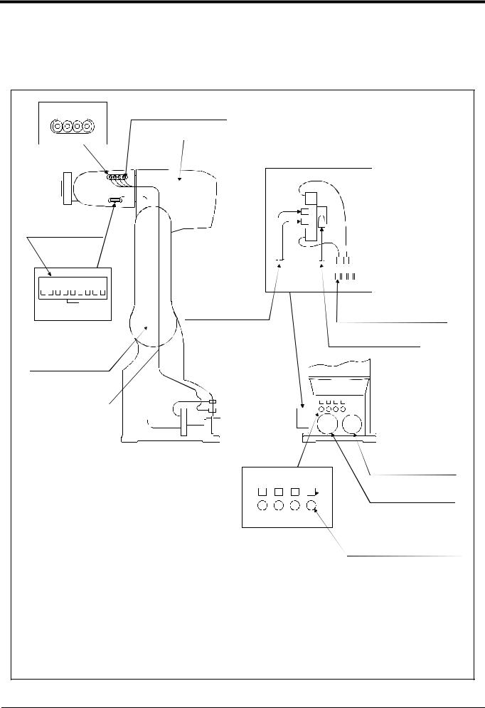
Robot arm
2.5 Tooling
2.5.1 Wiring and piping for hand
Shows the wiring and piping configuration for a standard-equipped hand.
(1) RV-1A/2AJ (General environment)
Number of coupling for hand |
|
AIR OUT |
(3) 1 to 4 : Secondary piping |
1 2 3 4 |
couplings (φ4) |
|
Note) This parts dosn't exist for 5-axis type |
|
Note) Solenoid valve set(optional) |
|
installation section |
|
a) |
(1) Hand input signal or |
|
motorized hand |
|
connectors |
|
|
b) |
9 8 7 6 5 4 3 2 1
|
Secondary piping |
GR1 to GR4 : Connect to the b) |
|
pneumatic hoses(φ4) |
Hand output connector |
||
Hand connector pin assignment |
|||
Note2) |
|
Primary piping pneumatic hoses(φ6*1)
Hand input signal and  Note2) motorized hand
cables
Secondary piping hoses (φ4*4)
CN2 |
CN1 |
Magnification |
Machine cable connector |
|
(Power supply) |
GR1 GR2 GR3 GR4 |
Machine cable connector |
Note1)When using the hand output signal, it is necessary |
|
to use the optional pneumatic hand interface |
(Signals) |
(2A-RZ365/2A-RZ375) |
1 2 3 4 |
|
Note2)The user must prepare the φ4 and φ6 |
(2)GR1 to GR4:Connect to the b) |
|
pneumatic hoses for connecting to the solenoid |
AIR IN |
Hand output connector |
|
valve set. |
|
Number of connector |
|
|
|
|
|
||
|
|
|
|
for hand output. |
|
(4) AIR IN 1 to 4:Connect to the a) |
||||
|
|
|
|
Number of coupling for hand. |
||||||
|
|
|
|
|
|
|
Secondary piping air coupling(φ4) |
|||
Connector and pneumatic coupling |
|
|
|
|
|
|
|
|||
|
|
|
|
|
|
|
|
|
|
|
|
|
|
Robot side(Robot arm side) |
Counter side (customer-prepared) |
|
|
|
|||
No |
Name |
Qty. |
|
|
|
|
|
Manufacturer |
|
|
Connectors, |
|
|
|
|
|
|||||
|
|
|
Connector pins |
Connector |
Connector pins |
|
|
|
||
|
|
|
couplings |
|
|
|
||||
|
|
|
|
|
|
|
|
|
|
|
|
|
|
|
|
|
|
|
|
||
|
|
|
|
|
|
|
|
|
|
|
(1) |
Connector |
1 |
SMP-09V-BC |
BHF-001GI-0.8BS |
SMP-09V-B |
BYM-001T-0.6 |
Japan solderless ter- |
|
||
|
|
|
|
|
|
|
|
minal MFG. Co.,LTD |
|
|
(2) |
Connector |
4 |
SMP-02V-BC |
BHF-001GI-0.8BS |
SMR-02V-B |
BYM-001T-0.6 |
|
|||
|
|
|
||||||||
|
|
|
|
|
|
|
|
|
|
|
(3) |
Coupling |
4 |
TSH4-M5M |
|
|
|
|
Koganei |
|
|
|
|
|
|
|
|
|
|
|
|
|
(4) |
Coupling |
4 |
UKBL4 |
|
|
|
|
|
|
|
|
|
|
|
|
|
|
|
|
|
|
Fig.2-8 Wiring and piping for hand (RV-1A/2AJ)
2-14 Tooling
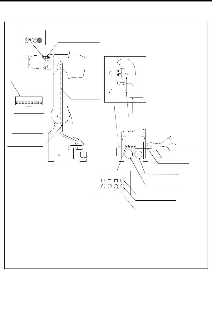
Robot arm
(2) RV-1AC-SB/2AJC-SB (Clean specification)
Number of coupling for hand AIR OUT
1 2 3 4 (3) 1 to 3 : Secondary piping 


 couplings (φ4)
Not use |
Note) This parts dosn't exist |
|
for 5-axis type |
||
|
Note3) Solenoid valve set
(optional, not clean secification) installation section
a)
(1) Hand input signal or motorized hand connectors
9 8 7 6 5 4 3 2 1 |
Internal suction φ4 |
|
|
||
|
Secondary piping |
|
pneumatic hoses(φ4) |
||
Hand connector pin assignment |
||
Note2) |
Hand input signal and motorized hand cables
Not use
Secondary piping hoses

 b)
b)
GR1 to GR4 : Connect to the b)
Hand output connector
Primary piping pneumatic hoses(φ6*1)
Note2)
Exhaustφ6 Note3
φ4x4: One of those is used for internal suction
Note1)When using the hand output signal, it is necessary to use the optional pneumatic hand interface. (2A-RZ365/2A-RZ375)
Note2)The user must prepare the φ4 and φ6
pneumatic hoses for connecting to the solenoid valve set.
Note3)The φ 6 pneumatic hose (for exhaust and compressed air) and φ 4 pneumatic hose (for suction) must be prepared by the user.
Note4)The vacuum solenoid valve must be fixed by the user.
Note5)Suction is possible by connecting the vacuum pump which is prepared by the user. In this case, select a flow rate of 50 liters/min. as a guideline.
|
|
|
|
|
Compressed airφ6 Note3) |
|
|
|
|
CN2 |
CN1 |
Vacuum solenoid valve Note4) |
|
|
|
|
|
|
||
|
|
|
|
|
For suctionφ4 Note5) |
|
Magnification |
|
|
|
Machine cable connector |
||
|
|
|
|
|
(Power supply) |
|
GR1 GR2 GR3 GR4 |
|
Machine cable connector |
||||
|
|
|
|
|
||
|
|
|
|
|
(Signals) |
|
1 |
2 |
3 |
4 |
(2)GR1 to GR4:Connect to the b) |
||
Hand output connector |
||||||
|
AIR IN |
|
||||
|
|
|
|
|||
Number of connector |
Coupling for internal suction |
|
for hand output. |
||
|
||
Number of coupling for hand. |
(4) AIR IN 1 to 4:Connect to the a) |
|
|
||
|
Secondary piping air coupling(φ4) |
Connector and pneumatic coupling
|
|
|
Robot side(Robot arm side) |
Counter side (customer-prepared) |
|
|
|||
No |
Name |
Qty. |
|
|
|
|
Manufacturer |
||
Connectors, |
|
|
|
||||||
|
|
|
Connector pins |
Connector |
Connector pins |
|
|
||
|
|
|
couplings |
|
|
||||
|
|
|
|
|
|
|
|
||
|
|
|
|
|
|
|
|
||
|
|
|
|
|
|
|
|
|
|
(1) |
Connector |
1 |
SMP-09V-BC |
BHF-001GI-0.8BS |
SMP-09V-B |
BYM-001T-0.6 |
Japan solderless ter- |
||
|
|
|
|
|
|
|
minal MFG. Co.,LTD |
||
(2) |
Connector |
4 |
SMP-02V-BC |
BHF-001GI-0.8BS |
SMR-02V-B |
BYM-001T-0.6 |
|||
|
|
||||||||
|
|
|
|
|
|
|
|
||
(3) |
Coupling |
3 |
TSH4-M5M |
|
|
|
Koganei |
||
|
|
|
|
|
|
|
|
|
|
(4) |
Coupling |
4 |
UKBL4 |
|
|
|
|
|
|
|
|
|
|
|
|
|
|
|
|
Fig.2-9 Wiring and piping for hand (RV-1AC-SB/2AJC-SB)
Tooling 2-15

Robot arm
2.5.2 Internal air piping
(1) The robot has four φ4 x 2.5 urethane hoses from the pneumatic entrance on the base section to the foure- arm side.They are three in the case of clean specification.
(2)The hose end section has four coupling bridges for a φ4 hose on both the base and forearm side. In the case of clean specification robot, the base side hoses are four and fore arm side hoses are three.
(3)The robot can have up to two pneumatic valve sets on the side of base (optional).
(4)Refer to Page 31, "Solenoid valve set" for details on the electronic valve set (optional).
2.5.3Internal wiring for the pneumatic hand output cable
(1) The hand output cable extends from the connector of the base section to the side of the base section.
(AWG#24(0.2mm2) x 2 : 4 cables) The cable terminals have connector bridges for four hand outputs. The connector names are GR1 to GR4.
2.5.4 Internal wiring for the hand check input cable
(1) The hand check input cable is wired to four points on the forearm side from the base.
2-16 Tooling
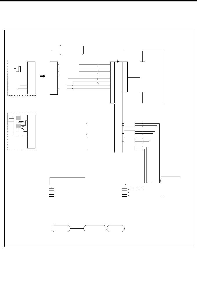
Robot arm
2.5.5 Wiring and piping system diagram for hand
Shows the wiring and piping configuration for a standard-equipped hand.
(1) RV-1A/2AJ (General environment)
<Sink type>
1
2
3
4
5
6
7
8
9
During use of motorized
hand I/F(optional)
 1
1
2
3 4 5 6 7 8 9
During use of pneumatic
hand I/F(optional)
1
2
3
4
5
6
7
8
9
During use of pneumatic hand I/F.
<Hand check 1> |
White |
||
Black |
|||
<Hand check 2> |
|||
White |
|||
<Hand check 3> |
|||
Black |
|||
<Hand check 4> |
|||
White |
|||
<+24V> |
|
||
|
Black |
||
<0V(COM)> |
|
||
White |
*1 |
||
<DC+> |
Black |
*1 |
|
<DC-> |
|||
|
|
||
Note1 *1 is dedicated for the motorized hand.
It is valid when the motorized hand interface is installed.
General-purpose input No.
900
901
902
903 Robot controller
<Hand check 1> |
|
|
|
|
|
|
|
|
|
|
|
|
|
GR1 |
|
<Hand check 1> |
|
|
900 |
|
|
White |
|
|
|
General-purpose output |
|
|
|
||
|
|
|
|
||||
|
Hand 1 |
+24V |
|
|
Black |
||
|
|
|
|
|
GR2 |
|
|
<+24V> |
ON/OFF |
|
901 |
|
|
White |
|
General-purpose output |
|
|
|
||||
<0V(COM)> |
|
+24V |
|
|
Black |
||
|
|
902 |
|
|
GR3 |
White |
|
|
|
|
|
|
|||
|
|
General-purpose output |
|
|
|
||
|
Hand 2 |
+24V |
|
|
Black |
||
|
|
|
|
||||
|
|
|
GR4 |
|
|||
|
ON/OFF |
General-purpose output |
903 |
|
|
White |
|
|
|
|
|||||
|
|
|
|
|
Black |
||
|
|
|
+24V |
|
|
|
|
|
|
|
|
|
|
|
|
φ4 quick coupling bridge(1 to 4)
AIR OUT1 |
φ4 hose(4 hoses) |
|
|
AIR OUT2 |
|
AIR OUT3 |
|
AIR OUT4 |
|
|
|
Solenoid valve |
φ quick |
|
section |
|
|
|
coupling |
|
|
AIR IN1 |
Solenoid valve |
|
AIR IN2 |
installation |
Solenoid valve |
AIR IN3 |
section |
manifold |
AIR IN4 |
(optional) |
|
Connect to the
primary air supply
(φ6 hose)
Wrist section |
Shoulder section Base section |
*Refer to Fig. 2-14 for air supply cir- cuit example.
Fig.2-10 Wiring and piping system diagram for hand and example the solenoid valve installation(Sink type)
Tooling 2-17
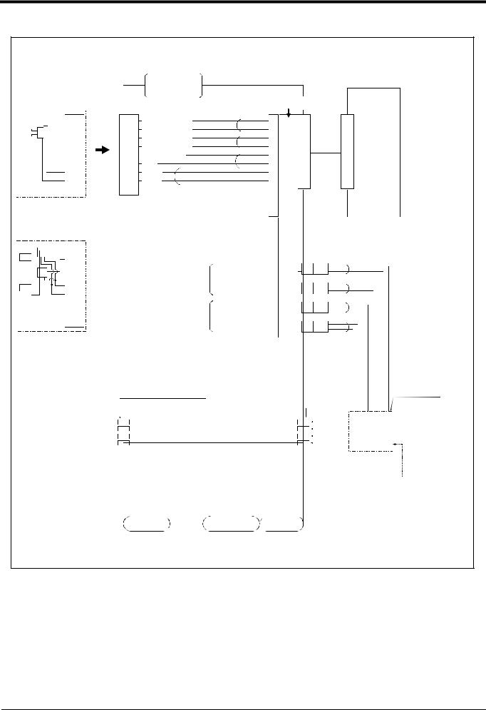
Robot arm
<Source type>
1
2
3
4
5
6
7
8
9
During use of motorized
hand I/F(optional)
|
During use of |
|
||
|
pneumatic |
|
||
|
hand I/F. |
|
|
|
|
<Hand check 1> |
White |
||
1 |
||||
Black |
||||
2 |
<Hand check 2> |
|||
White |
||||
3 |
<Hand check 3> |
|||
Black |
||||
4 |
<Hand check 4> |
|||
White |
||||
5 |
<+24V(COM)> |
|||
Black |
||||
6 |
<0V> |
|
||
White |
*1 |
|||
7 |
<DC+> |
|||
Black |
*1 |
|||
8 |
<DC-> |
|||
|
|
|||
9 |
|
|
|
|
|
|
|
|
|
Note1 *1 is dedicated for the motorized hand.
It is valid when the motorized hand interface is installed.
General-purpose input No.
900
901
902
903Robot controller
|
1 |
|
<Hand check 1> |
|
|
|
|
|
|
|
|
|
2 |
|
|
|
|
|
|
|
|
GR1 |
|
|
|
<Hand check 1> |
|
|
900 |
|
|
White |
|||
|
3 |
|
|
|
|
General-purpose output |
|
|
|
||
|
|
|
|
|
|
|
|||||
|
|
|
|
Hand 1 |
24G |
|
|
Black |
|||
|
4 |
|
|
|
|
|
|
|
GR2 |
|
|
|
|
|
|
|
|
|
|
||||
|
|
|
|
|
|
|
|
|
|||
|
|
|
|
|
ON/OFF |
|
|
|
|
White |
|
5 |
|
<+24V(COM)> |
General-purpose output |
901 |
|
|
|
||||
|
|||||||||||
|
|
|
|
|
|
24G |
|
|
Black |
||
6 |
<0V> |
|
|
||||||||
|
|
|
|
||||||||
|
|
|
|
|
GR3 |
|
|||||
7 |
|
|
|
|
|
902 |
|
|
White |
||
|
|
|
|
General-purpose output |
|
|
|
||||
8 |
|
|
|
Hand 2 |
24G |
|
|
Black |
|||
|
|
|
|
|
|
||||||
|
|
|
|
|
GR4 |
|
|||||
9 |
|
|
|
ON/OFF |
General-purpose output |
903 |
|
|
White |
||
|
|
|
|
|
|||||||
|
|
|
|
|
|
|
|
|
Black |
||
|
|
|
|
|
|
|
24G |
|
|
|
|
During use of pneumatic
hand I/F(optional)
|
Solenoid valve |
φ4 quick coupling bridge(1 to 4) |
section |
|
φ quick |
|
coupling |
AIR OUT1 |
φ4 hose(4 hoses) |
|
|
AIR OUT2 |
|
AIR OUT3 |
|
AIR OUT4 |
|
AIR IN1 |
Solenoid valve |
|
AIR IN2 |
installation |
Solenoid valve |
AIR IN3 |
section |
manifold |
AIR IN4 |
(optional) |
|
Connect to the
primary air supply
(φ6 hose)
Wrist section |
Shoulder section Base section |
*Refer to Fig. 2-14 for air supply cir- cuit example.
Fig.2-11 Wiring and piping system diagram for hand and example the solenoid valve installation(Source type)
2-18 Tooling
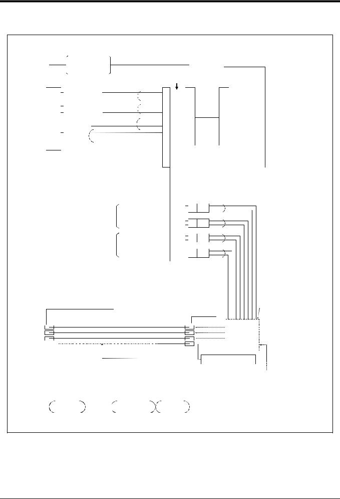
Robot arm
(2) RV-1AC-SB/2AJC-SB (Clean specification)
<Sink type>
|
During use of |
|
|
|
|
|
|
|
|
|
|
|
pneumatic |
|
|
|
|
|
|
|
|
|
|
|
hand I/F. |
|
|
|
General |
- |
purpose |
|
|
||
|
|
|
|
|
|
|
|||||
|
|
|
|
|
input No. |
|
|
|
|||
|
<Hand check 1> |
White |
|
900 |
|
|
|
|
|
|
|
1 |
|
|
|
|
|
|
|
||||
Black |
|
|
|
|
|
|
|
||||
2 |
<Hand check 2> |
|
901 |
|
|
|
|
|
|
||
White |
|
|
|
|
|
|
|
||||
3 |
<Hand check 3> |
|
902 |
|
|
|
|
|
|
||
Black |
|
|
|
|
|
|
|
||||
4 |
<Hand check 4> |
|
903 |
|
|
|
|
|
Robot |
||
White |
|
|
|
|
|
|
|||||
5 |
<+24V> |
|
|
|
|
|
|
|
|
||
|
Black |
|
|
|
|
|
|
|
controller |
||
6 |
<0V(COM)> |
|
|
|
|
|
|
|
|
||
|
|
|
|
|
|
|
|
|
|||
White |
|
|
|
|
|
|
|
|
|
||
7 |
<Not use> |
|
|
|
|
|
|
|
|
|
|
8 |
<Not use> |
Black |
|
|
|
|
|
|
|
|
|
9 |
|
|
|
|
|
|
|
|
|
|
|
|
|
|
|
|
|
|
|
|
|
|
|
|
|
|
|
|
|
|
|
|
|
|
|
|
|
|
|
|
|
|
|
|
|
|
|
|
|
900 |
|
|
GR1 |
White |
|
General-purpose output |
|
|
|
||
Hand 1 |
+24V |
|
|
Black |
||
|
|
|
|
GR2 |
|
|
ON/OFF |
|
901 |
|
|
White |
|
General-purpose output |
|
|
|
|||
|
+24V |
|
|
Black |
||
|
|
902 |
|
|
GR3 |
White |
|
General-purpose output |
|
|
|
||
Hand 2 |
+24V |
|
|
Black |
||
|
|
|
||||
|
|
GR4 |
|
|||
ON/OFF |
General-purpose output |
903 |
|
|
White |
|
|
|
|||||
|
|
|
|
Black |
||
|
|
+24V |
|
|
|
|
|
|
|
|
|
|
|
|
|
|
|
Solenoid valve |
|
φ4 quick coupling bridge(1 to 4) |
φ quick |
|
section |
|
|
|
|
|
|
|
coupling |
|
|
AIR OUT1 |
φ4 hose(4 hoses) |
AIR IN1 |
Solenoid valve |
Solenoid valve |
AIR OUT2 |
|
AIR IN2 |
installation |
|
|
AIR IN3 |
manifold |
||
AIR OUT3 |
|
section |
||
|
AIR IN4 |
(optional) |
Connect to the |
|
|
|
|||
|
|
|
|
primary air supply
Internal suction
Vacuum solenoid valve 
(φ6 hose)
Wrist section |
Shoulder section Base section |
*Refer to Fig. 2-14 for air supply cir- |
|
|
|
|
|
cuit example. |
Fig.2-12 Wiring and piping system diagram for hand and example the solenoid valve installation(Sink type)
Tooling 2-19
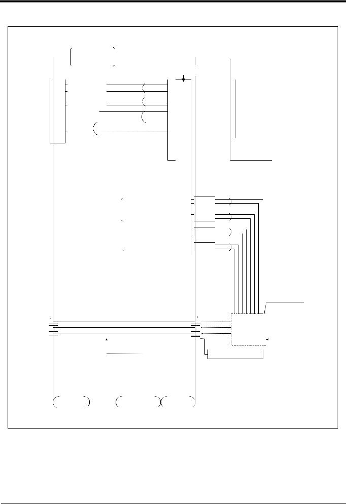
Robot arm
<Source type>
|
During use of |
|
|
|
|
|
|
|
|
|
|
|
pneumatic |
|
|
|
|
|
|
|
|
|
|
|
hand I/F. |
|
|
|
General |
- |
purpose |
|
|
||
|
|
|
|
|
|
|
|||||
|
|
|
|
|
input No. |
|
|
|
|||
|
<Hand check 1> |
White |
|
900 |
|
|
|
|
|
|
|
1 |
|
|
|
|
|
|
|
||||
Black |
|
|
|
|
|
|
|
||||
2 |
<Hand check 2> |
|
901 |
|
|
|
|
|
|
||
White |
|
|
|
|
|
|
|
||||
3 |
<Hand check 3> |
|
902 |
|
|
|
|
|
|
||
Black |
|
|
|
|
|
|
|
||||
4 |
<Hand check 4> |
|
903 |
|
|
|
|
|
Robot |
||
White |
|
|
|
|
|
|
|||||
5 |
<24V(COM)> |
|
|
|
|
|
|
|
|||
Black |
|
|
|
|
|
|
|
controller |
|||
6 |
<0V> |
|
|
|
|
|
|
|
|
||
|
|
|
|
|
|
|
|
|
|||
White |
|
|
|
|
|
|
|
|
|
||
7 |
<Not use> |
|
|
|
|
|
|
|
|
|
|
8 |
<Not use> |
Black |
|
|
|
|
|
|
|
|
|
9 |
|
|
|
|
|
|
|
|
|
|
|
|
|
|
|
|
|
|
|
|
|
|
|
|
|
|
|
|
|
|
|
|
|
|
|
|
|
|
|
|
|
|
|
|
|
|
|
|
|
900 |
|
|
GR1 |
White |
|
General-purpose output |
|
|
|
||
Hand 1 |
24G |
|
|
Black |
||
|
|
|
||||
|
|
|
|
GR2 |
|
|
ON/OFF General-purpose output |
901 |
|
|
White |
||
|
|
|
||||
|
|
Black |
||||
|
|
24G |
|
|
|
|
|
|
902 |
|
|
GR3 |
White |
|
General-purpose output |
|
|
|
||
Hand 2 |
24G |
|
|
Black |
||
|
|
|
||||
|
|
GR4 |
|
|||
ON/OFF |
General-purpose output |
903 |
|
|
White |
|
|
|
|||||
|
|
|
|
Black |
||
|
|
24G |
|
|
|
|
|
|
|
|
|
|
|
|
Solenoid valve |
φ4 quick coupling bridge(1 to 4) |
section |
|
φ quick |
|
coupling |
AIR OUT1 |
φ4 hose(4 hoses) |
|
|
AIR OUT2 |
|
AIR OUT3 |
|
Internal suction
AIR IN1 |
Solenoid valve |
|
AIR IN2 |
installation |
Solenoid valve |
AIR IN3 |
section |
manifold |
AIR IN4 |
(optional) |
Connect to the |
primary air supply
Vacuum solenoid valve 
 (φ6 hose)
Wrist section |
Shoulder section Base section |
*Refer to Fig. 2-14 for air supply cir- |
|
|
|
|
|
cuit example. |
Fig.2-13 Wiring and piping system diagram for hand and example the solenoid valve installation(Source type)
2-20 Tooling
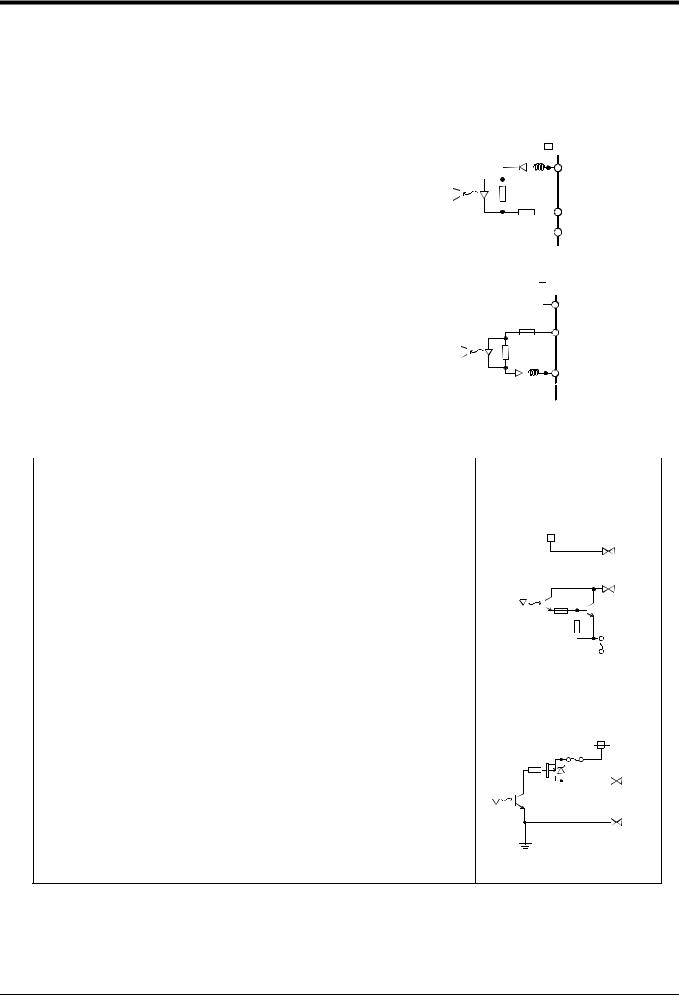
Robot arm
2.5.6 Electrical specifications of hand input/output
Table 2-6 Electrical specifications of input circuit
Item |
|
|
|
Specifications |
|
|
|
|
|
|
|
|
|
Internal circuit |
||||||||||||||||||||||||||||||||
|
|
|
|
|
|
|
|
|
|
|
|
|
|
|
|
|
|
|
|
|
|
|
|
|
|
|
|
|
|
|
|
|
|
|
|
|
|
|
|
|
|
|
|
|
|
|
|
|
|
|
|
|
|
|
|
|
|
|
|
|
|
|
|
|
|
|
|
|
|
|
|
|
|
|
|
|
|
|
|
|
|
|
|
|
|
|
|
|
|
|
|
|
|
Type |
|
|
DC input |
<Sink type> |
|
|
|
|
|
|
|
|
|
|
|
|
|
|
|
|||||||||||||||||||||||||||
No. of input points |
|
|
4 |
|
|
|
|
|
|
|
|
|
|
|
|
24V |
|
|
|
|
|
|
|
|
|
|
|
|
|
|
|
|
|
|
|
|
||||||||||
|
|
|
|
|
|
|
|
|
|
|
|
|
|
|
|
|
|
|
|
|
|
|
|
|
|
|
|
|
|
|
|
|
|
|
|
|
||||||||||
Insulation method |
|
|
Photo-coupler insulation |
|
|
|
|
|
|
|
|
|
|
|
|
|
|
24V |
||||||||||||||||||||||||||||
|
|
|
|
|
|
|
|
|
|
|
|
|
|
|
|
|
|
|
|
|
|
|
|
|
|
|
|
|||||||||||||||||||
|
|
|
|
|
|
|
|
|
|
|
|
|
|
|
|
|
|
|
|
|
|
|
|
|
|
|
|
|
|
|
|
|||||||||||||||
Rated input voltage |
12VDC/24VDC |
|
|
|
|
|
|
|
|
|
|
|
|
|
|
|
|
|
|
|
|
|
|
|
|
|
|
|||||||||||||||||||
|
|
|
|
|
|
|
|
|
|
|
|
|
|
|
|
|
|
|
|
|
|
|
|
|
|
|
|
|
|
|
|
|
|
|
|
|
|
|
|
|
||||||
|
|
|
|
|
|
|
|
|
|
|
|
|
|
|
|
|
|
|
|
|
|
|
|
|
|
|
|
|
|
|
|
|
|
|
|
|
|
|
|
|
|
|
|
|
||
Rated input current |
Approx. 3mA/approx. 7mA |
|
|
|
|
|
|
|
|
|
820 |
|
|
|
|
|
|
|
|
|
|
HCn* |
|
|||||||||||||||||||||||
|
|
|
|
|
|
|
|
|
|
|
|
|
|
|
|
|
|
|
||||||||||||||||||||||||||||
|
|
|
|
|
|
|
|
|
|
|
|
|
|
|
|
|
|
|
|
|
|
|
|
|||||||||||||||||||||||
Working voltage range |
DC10.2 to 26.4V(ripple rate within 5%) |
|
|
|
|
|
|
|
|
|
|
|
|
|
|
|
|
|
|
|
|
|
|
|
|
|
|
|||||||||||||||||||
|
|
|
|
|
|
|
|
|
|
|
|
|
|
|
3.3K |
|
|
|
|
|
|
|
|
|
|
|
|
|
|
|
||||||||||||||||
ON voltage/ON current |
8VDC or more/2mA or more |
|
|
|
|
|
|
|
|
|
0V(COM) |
|||||||||||||||||||||||||||||||||||
OFF voltage/OFF current |
4VDC or less/1mA or less |
|
|
|
|
|
|
|
|
|
|
|
|
|
|
|
|
|
|
|
|
|
|
|
|
|
|
|
|
|
|
|
|
|
|
|
|
|
|
|
|
|
||||
|
|
|
|
|
|
|
|
|
|
|
|
|
|
|
|
|
|
|
|
|
|
|
|
|
|
|
|
|
|
|
|
|
|
|
|
|
|
|
|
|
|
|
|
|
|
|
Input resistance |
|
|
Approx. 3.3kΩ |
<Source type> |
|
|
|
|
|
|
|
|
|
|
|
|
|
|
|
|||||||||||||||||||||||||||
|
|
|
|
|
|
|
|
|
|
|
|
|
|
|
|
|
|
|
|
|
||||||||||||||||||||||||||
Response time |
|
OFF-ON |
10ms or less(DC24V) |
|
|
|
|
|
|
|
|
|
|
|
|
|
|
|
||||||||||||||||||||||||||||
|
|
|
|
|
|
|
|
|
|
24V |
|
|
|
|
|
|
|
|
|
|
|
|
|
|
|
|
|
|
|
|
|
|
|
|||||||||||||
|
|
ON-OFF |
10ms or less(DC24V) |
|
|
|
|
|
|
|
|
|
|
|
|
|
|
24V(COM) |
|
|||||||||||||||||||||||||||
|
|
|
|
|
|
|
|
|
|
|
|
|
|
|
|
|
|
|
|
|
|
|
|
|
|
|
|
|||||||||||||||||||
|
|
|
|
|
|
|
|
|
|
|
|
|
|
|
|
|
|
|
|
|
|
|
|
|
|
|
|
|
|
|
|
|||||||||||||||
|
|
|
|
|
|
|
|
|
|
|
|
|
|
|
3.3K |
HCn* |
|
|||||||||||||||||||||||||||||
|
|
|
|
|
|
|
|
|
|
|
|
|
|
|
|
|
|
|
|
|
|
|
|
|
|
|
|
|
|
|
|
|||||||||||||||
|
|
|
|
|
|
|
|
820 |
|
|
|
|
|
|
|
|
|
|
|
|
|
|
|
|
|
|
|
|
|
|
|
|
|
|
||||||||||||
|
|
|
|
|
|
|
|
|
|
|
|
|
|
|
|
|
|
|
|
|
|
|
|
|
|
|
|
|
|
|
|
|
||||||||||||||
|
|
|
|
|
|
|
|
|
|
|
|
|
|
|
|
|
|
|
|
|
|
|
|
|
|
|
|
|
|
|
|
|
|
|
|
|
|
|
|
|
|
|
|
|
|
|
|
|
|
|
|
|
|
|
|
|
|
|
|
|
|
|
|
|
|
|
|
|
|
|
|
|
|
|
|
|
|
|
0V |
||||||||||||||
|
|
|
|
|
|
* HCn HC1 HC4 |
|
|
|
|
|
|
|
|
|
|
|
|
|
|
|
|||||||||||||||||||||||||
|
|
|
|
|
|
|
|
|
|
|
|
|
|
|
|
|
|
|
|
|
|
|
|
|
|
|
|
|
|
|
|
|
|
|
|
|
|
|
|
|
|
|
|
|
|
|
Table 2-7 Electrical specifications of output circuit |
|
|
|
|
|
|
|
|
|
|
|
|
|
|
|
|
|
|
|
|
|
|
|
|
|
|
|
|
|
|
|
|
|
|
|
|
|
|
|
|
|
|||||
|
|
|
|
|
|
|
|
|
|
|
|
|
|
|
|
|
|
|
|
|
|
|
|
|
|
|
|
|
|
|
|
|
|
|
|
|
|
|
|
|
|
|
|
|||
Item |
|
Specification |
|
|
|
|
|
|
|
|
|
|
|
|
|
|
|
|
Internal circuit |
|||||||||||||||||||||||||||
|
|
|
|
|
|
|
|
|
|
|
|
|
|
|
|
|
|
|
|
|
|
|
|
|
|
|
|
|
|
|
|
|
|
|
|
|
|
|
|
|
|
|
|
|
|
|
|
|
|
|
|
|
|
|
|
|
|
|
|
|
|
|
|
|
|
|
|
|
|
|
|
|
|
|
|
|
|
|
|
|
|
|
|
|
|
|
|
|
|
|
|
|
|
Type |
|
|
|
Transistor output |
|
|
|
|
|
<Sink type> |
|
|
|
|
|
|
|
|
|
|
|
|
|
|
|
|||||||||||||||||||||
No. of output points |
|
4 |
|
|
|
|
|
|
|
|
|
|
|
|
|
|
|
|
|
|
|
24V |
|
|
|
|
|
|
|
|
|
|
|
|
|
|
|
|||||||||
Insulation method |
|
|
|
Photo coupler insulation |
|
|
|
|
|
|
|
Internal power supply |
||||||||||||||||||||||||||||||||||
|
|
|
|
|
|
|
|
|
|
|
|
|
|
|
|
|
|
|
|
|
|
|
|
|
|
|
|
|
|
|
|
|
|
|
|
|
|
|
|
|
|
|
|
|
|
|
Rated load voltage |
|
|
|
DC24V |
|
|
|
|
|
|
|
|
|
|
|
|
|
|
|
|
|
|
|
|
|
|
|
|
|
|
|
|
|
|
|
|
|
|
|
|
|
|
|
|
|
|
|
|
|
|
|
|
|
|
|
|
|
|
|
|
|
|
|
|
|
|
|
|
|
|
|
|
|
|
|
|
|
|
|
|
|
|
|
|
|
|
|
|
|
|
|||
|
|
|
|
|
|
|
|
|
|
|
|
|
|
|
|
|
|
|
|
|
|
|
|
|
|
|
|
|
|
|
|
|
|
|
|
|
|
|
|
|
|
|
|
|||
Rated load voltage range |
|
DC21.6 to 26.4VDC |
|
|
|
|
|
|
|
|
|
|
|
|
|
|
|
|
|
|
|
|
|
|
|
|
|
|
|
|
|
|
|
|
|
|
|
|
|
|
|
|
|
|||
|
|
|
|
|
|
|
|
|
|
|
|
|
|
|
|
|
|
|
|
|
|
|
|
|
|
|
|
|
|
|
|
|
|
|
|
GRn* |
||||||||||
Max. current load |
|
|
|
0.1A/ 1 point (100%) |
|
|
|
|
|
|
|
|
|
|
|
|
|
|
|
|
|
|
|
|
|
|
|
|
|
|
|
|
|
|
|
|||||||||||
Current leak with power OFF |
|
0.1mA or less |
|
|
|
|
|
|
|
|
|
|
|
|
|
|
|
|
|
|
|
|
|
|
|
|
|
|
|
|
|
|
|
|
|
|
|
|
|
|
|
|
|
|||
Maximum voltage drop with power ON |
DC0.9V(TYP.) |
|
|
|
|
|
|
|
|
|
|
|
|
|
|
|
|
|
|
|
|
|
|
|
|
|
|
|
|
|
|
|
|
|
|
|
|
|
|
|
|
|
||||
|
|
|
|
|
|
|
|
|
|
|
|
|
|
|
|
|
|
|
|
|
|
|
|
|
|
|
|
|
|
|
|
|
|
|
|
|
|
|
|
|
|
|
|
|
|
|
Response time |
|
OFF-ON |
2ms or less (hardware response time) |
|
|
|
|
|
|
|
|
|
|
|
|
|
|
|
|
|
|
|
|
|
|
|
|
|
|
|
|
|
|
|
|
|
|
|
|
|
|
|
|
|
||
|
|
|
|
|
|
|
|
|
|
|
|
|
|
|
|
|
|
|
|
|
|
|
|
|
|
|
|
|
|
|
|
|
Fuse |
|||||||||||||
|
|
|
ON-OFF |
2 ms or less (resistance load) (hardware response time) |
|
|||||||||||||||||||||||||||||||||||||||||
|
|
|
|
|
|
|
|
|
|
|
|
|
|
|
|
|
|
|
|
|
|
|
|
|
|
|
|
|
|
|
|
|
1.6A |
|
|
|
|
|||||||||
|
|
|
|
|
|
|
|
|
|
|
|
|
|
|
|
|
|
|
|
|
|
|
|
|
|
|
|
|
|
|
|
|
|
|||||||||||||
Fuse rating |
|
|
|
1.6A (each one common) Cannot be exchanged |
||||||||||||||||||||||||||||||||||||||||||
|
|
|
|
|
|
|
|
|
|
|
|
|
|
|
|
|
|
|||||||||||||||||||||||||||||
|
|
|
|
|
|
|
|
|
|
|
|
|
|
|
|
|
|
|
|
|
|
|
|
|
|
|
|
|
|
|
|
|
|
|
|
|
|
|
|
|
|
|
|
|
|
|
|
|
|
|
|
|
|
|
|
|
|
|
|
|
|
|
|
|
|
|
|
|
|
|
|
|
|
|
|
|
|
|
|
|
|
|
|
|
|
|
|
|
|
|
|
|
|
|
|
|
|
|
|
|
|
|
|
|
|
|
|
|
|
|
|
|
|
|
|
|
|
|
|
|
|
|
|
|
|
|
|
|
|
|
|
|
|
|
|
|
|
|
|
|
0V
<Source type>
Fuse 24V
GRn*
0V
* GRn GR1 GR4
Note) An optional air hand interface (2A-RZ365/RZ375) is required to use hand output.
Tooling 2-21

2 Robot arm
2.5.7 Air supply circuit example for the hand
Fig. 2-14 shows an example of pneumatic supply circuitry for the hand. (1) Place diodes parallel to the solenoid coil.
(2)When the factory pneumatic pressure drops, as a result of the hand clamp strength weakening, there can be damage to the work. To prevent it, install a pressure switch to the source of the air as shown in Fig. 2-14 and use the circuit described so that the robot stops when pressure drops. Use a hand with a spring-pressure clamp, or a mechanical lock-type hand, that can be used in cases where the pressure switch becomes dam- aged.
|
|
|
|
|
|
|
Pressure switch |
|
|
|
|
|
|
|
|
|
To the solenoid valve |
|
|
|
|
|
|
|
|
|
|
|
|
|
|
|
|
|
primary air supply port |
Pneumatic source |
|
|
|
|
|
|
0.5MPa ±10% |
|
|
|
|
|
|
|
|
||
0.7MPa less |
Filter |
Regurater |
||||||
Fig.2-14 Air supply circuit example for the hand
2-22
Loading...