


PLK-G4030

Industrial Sewing Machine
TECHNICAL MANUAL
SEWING MACHINE HEAD
Electronic Pattern Sewing Machine
Model PLK-G4030
PLK-G6030
A180E646P01
FOR SAFE USE
Before the installation, operation, and inspection for this product, read the “FOR SAFE USE” and the
technical manuals carefully. Also read the other technical manuals, “Control Unit” and “Operation Panel”
describing some instructions, which are not in this manual, and use the sewing machine properly.
SAFETY INDICATIONS
DANGER
CAUTION
Indicates that incorrect handling may cause hazardous conditions, resulting
in death or severe injury.
Indicates that incorrect handling may cause hazardous conditions, resulting
in medium or slight personal injury or physical damage. Note that CAUTION
level may lead to a serious consequence according to the circumstances.
Always follow the instructions of both levels because they are important to
personal safety.
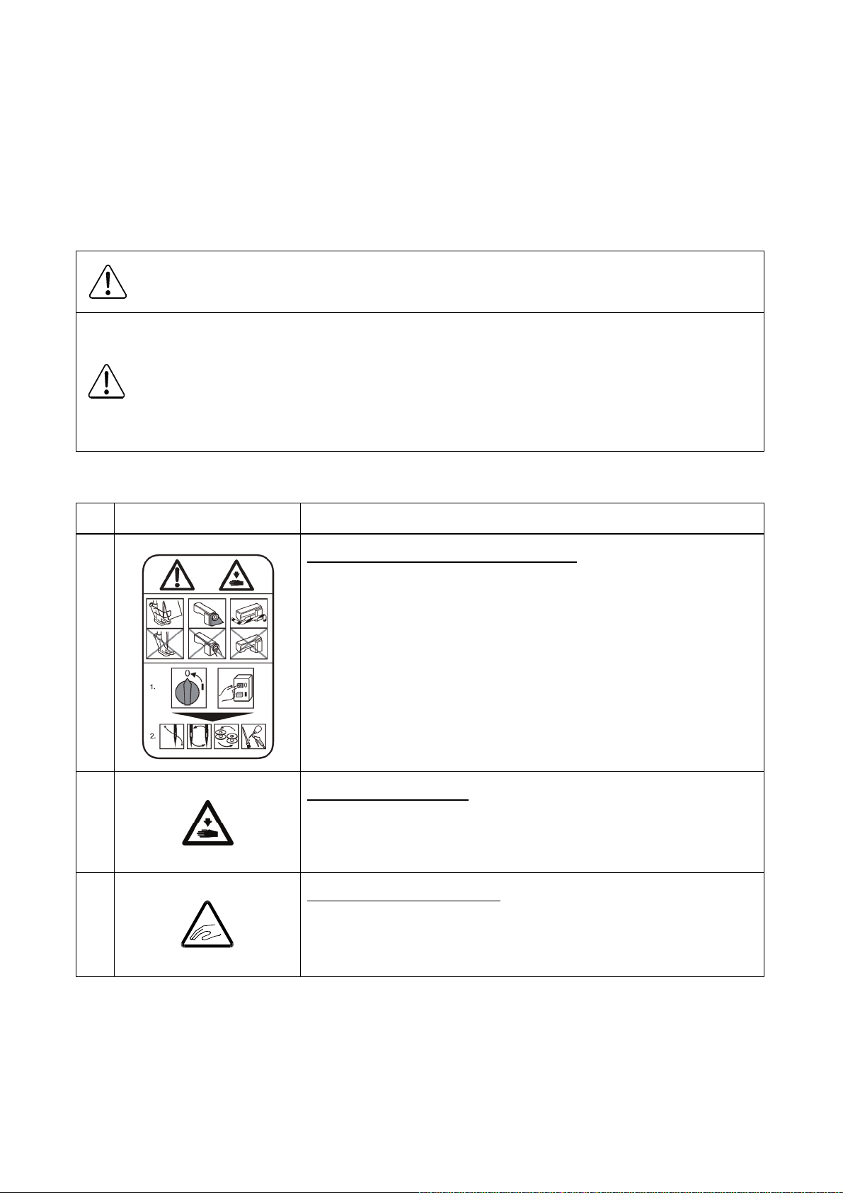
CAUTION INDICATIONS
No. Caution indication Description
1
Precaution for sewing machine operation
Indicates that removing the safety and operating the sewing
machine for some other purposes with power-on are prohibited.
Please do not operate the sewing machine without
protective equipment such as a needle guard, an eye guard,
:
a belt cover or the others.
Please turn off the power switch when threading, changing
a needle and a bobbin, cleaning, and lubricating.
2
3
Caution for fingers injury
Indicates a possibility of fingers (hands) injury in a certain
condition.
Caution for squeezing fingers
Indicates a possibility of squeezing fingers in a certain condition.
:
:

SAFETY PRECAUTIONS
DANGER
To prevent from receiving an electric shock, always turn off a power switch and unplug power supply
when opening a control box, and then open after ten minutes passes.
CAUTION
USAGE ENVIRONMENT
Please do not operate the sewing machine under the following conditions.
(1) In the ambient temperature of 35 degrees (95°F) or more than 35 degrees, or the ambient
temperature of 5 degrees or less than 5 degrees (41°F).
(2) In the ambient temperature of 55 degrees (131°F) or more than 55 degrees, or the ambient
temperature of -10 degrees or less than -10 degrees (18°F) during transportation.
(3) In the relative humidity exceeding 85% or less than 45%.
(4) In the open-air place or the location that receives direct sunlight.
(5) In the place near heat sources such as heating devices.
(6) In the atmosphere filled with dust, explosive gas, or corrosive gas.
(7) In the place where the fluctuation in the power voltage of 10% or more than 10%, or the power
voltage of -10% or less than -10% of the fixed power voltage.
(8) In the place where the power source cannot supply enough voltage to keep the motor running.
(9) In the place filled with strong electric noises such as high-frequency welders.
INSTALLATION
(1) Please have some specialists, who have enough experience for the sewing machine installations,
install the sewing machine.
(2) Please have a qualified electrician perform necessary electric wiring.
(3) Please do not operate until the sewing machine is repaired when any damage or fault is found on
the sewing machine at the installation.
(4) Please do not refurbish the sewing machine.
(5) The sewing machine is heavy. For the safety, please make sure to install the sewing machine head
by more than one person.
(6) Please make sure to fit the safety protective equipment (the motor cover or the others) and the
accessory protective equipment (the eye guard) that removed temporarily for installation.

SEWING
(1) Please make sure to turn the power switch off before installing or replacing needles.
(2) Please pay attention for the fingers not to be injured by the needle point.
(3) Please make sure to turn power switch off before lubricating.
(4) Please pay attention that oil does not get on your skin or in your eyes as it may cause an
inflammation.
(5) Please make sure to keep oil out of the reach of children who may drink oil by mistake.
(6) Please make sure to turn the power switch off before threading a needle.
(7) Before starting the sewing, please make sure the position and the function of the halt switch.
(8) Please do not touch the operating parts during sewing operation.
(9) It is very dangerous to operate the sewing machine without safety guards (eye guards, belt covers,
link covers, finger guards or the others).
Please make sure to operate the sewing machine with safety guards.
(10) Please make sure to turn the power switch off when stopping the sewing machine temporarily.
ADJUSTMENT
(1) Please make sure to turn the power switch off before adjusting the sewing machine.
(2) If the adjustment is required while the power switch on, do not step on the foot switch by mistake.
(3) Please be careful not to be injured by a sharp part such as the needle and the shuttle hook point.
(4) Please make sure to put the safety guards (eye guards, belt guards, link covers, and finger guards
or the others) back on the initial position after the sewing machine adjustment.

CONTENTS
1. STRUCTURE OF THE SEWING MACHINE····································
2. SPECIFICATION·······································································
3. INSTALLATION········································································
3-1. Installation of the foot switch····································································
3-2. Connection of the air tube·······································································
3-3. Installation of the thread stand·································································
3-4. Installation of the eye guard····································································
3-5. Installation of the spindle motor································································
4. LUBRICATION·········································································
41. Filling the oil tank···················································································
42. Oiling··································································································
5. PROPER OPERATION······························································
1
2
3
3
3
4
4
5
6
6
6
7
5-1. Initial setting of the control box·································································
5-2. Installation of the needle·········································································
5-3. Threading the upper thread·····································································
5-4. Winding the bobbin thread······································································
5-5. Setting the bobbin·················································································
5-6. Setting the bobbin case··········································································
6. SEWING·················································································
6-1. The sewing operation············································································
6-2. Operation of the halt switch·····································································
6-3. Adjustment of the thread tension······························································
6-4. Operation of the presser foot 2-stage lifting device·······································
6-5. Adjustment of the lifting volume································································
7
7
8
9
10
10
11
11
12
13
14
15

7. STANDARD ADJUSTMENT························································
7-1. Adjustment of the needle bar position························································
7-2. Adjustment of the position between the needle and the shuttle hook················
7-3. Adjustment of the clearance between the shuttle hook and the needle··············
7-4. Adjustment of the clearance between the driver and the needle······················
7-5. Adjustment of the shuttle race thread guide················································
7-6. Adjustment of the presser foot·································································
7-6-1. Adjustment of the presser foot position·················································
7-6-2. Adjustment of the presser foot lift during the sewing································
7-6-3. Adjustment of the presser foot timing····················································
7-7. Adjustment of the wiper··········································································
7-8. Adjustment of the bobbin winder······························································
7-9. Adjustment of the work holder·································································
7-9-1. Adjustment of the work holder pressure················································
7-9-2. Changing the work holder··································································
7-10. Adjustment of the trimmer cam follower····················································
16
16
16
17
18
19
19
19
21
22
23
24
24
24
24
25
7-11. Adjustment of the position of movable knife···············································
7-12. Adjustment of the blade drive arm spring force··········································
7-13. Adjustment of the fixed knife position·······················································
7-14. Adjustment of the thread take up spring swing stroke··································
7-15. Adjustment of the thread take up spring tension·········································
7-16. Adjustment of the thread tail after the trimming··········································
7-17. Adjustment of the upper thread tension release ·········································
7-18. Adjustment of the mechanical home position·············································
7-18-1. Adjustment of the X direction····························································
7-18-2. Adjustment of the Y direction····························································
7-19. Adjustment of the X-Y timing belt tension··················································
7-19-1. Adjustment of the X timing belt tension················································
7-19-2. Adjustment of the Y timing belt tension················································
8. MAINTENANCE·······································································
8-1. Cleaning·····························································································
26
26
27
28
28
28
29
30
31
32
33
33
34
35
35
8-2. Disposing of oil waste············································································
9. TROUBLESHOOTING·······························································
35
36
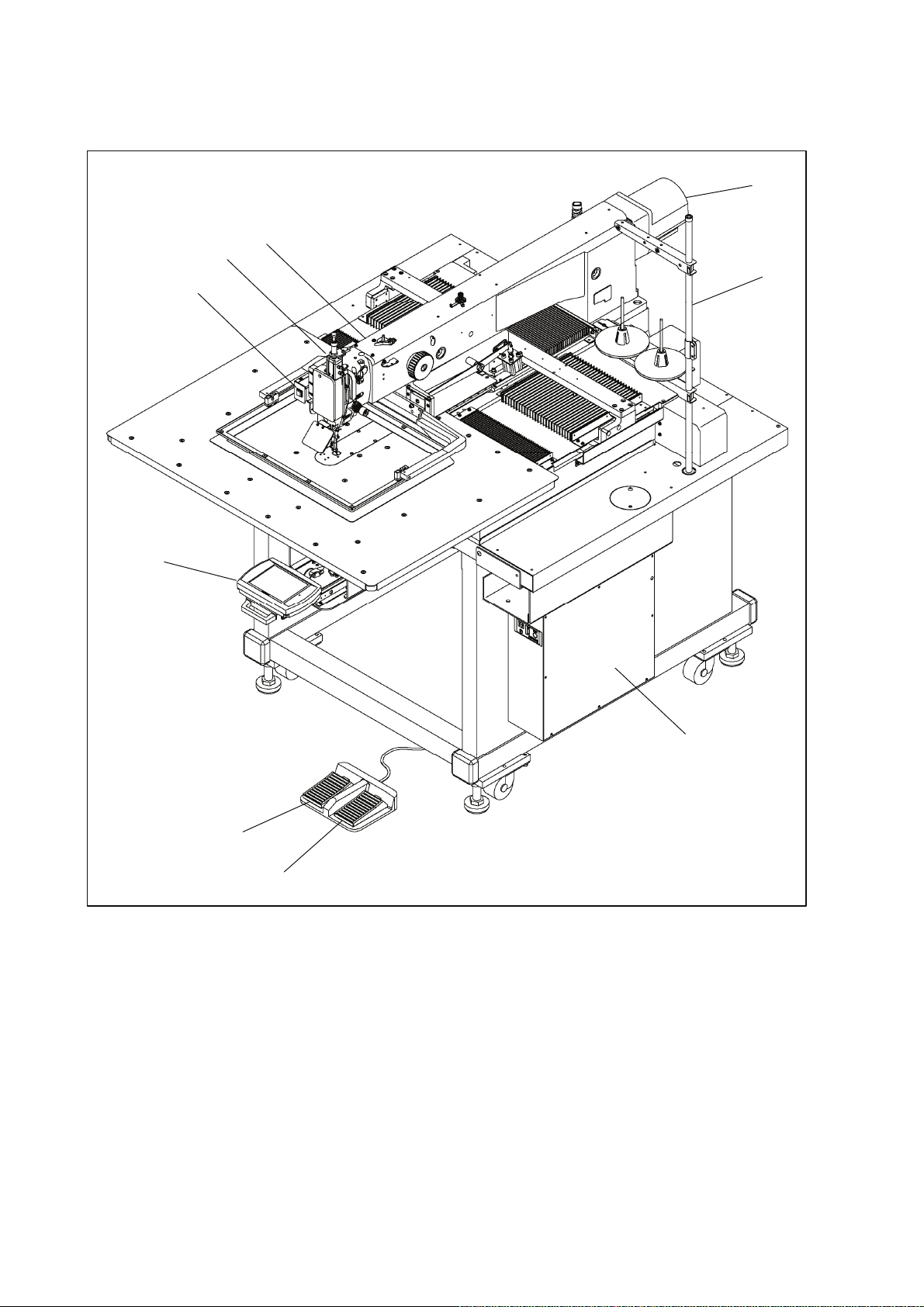
1. STRUCTURE OF THE SEWING MACHINE
PLK-G4030/G6030 electronic pattern sewing machine consists of the following main parts.
<3>
<5>
<1>
<9>
<2>
<8>
<1>: Sewing machine head <2>: Main shaft motor <3>: Halt switch <4>: Control box
<5>: Operation panel <6>: Work holder foot switch <7>: Start foot switch <8>: Thread stand
<9>: Presser foot 2-stage lifting device
<7>
<6>
<4>
- 1 -

2. SPECIFICATIONS
Model PLK-G4030 PLK-G6030
Sewing area
Maximum sewing speed 2,000rpm
Setting speed 10 speed levels in 200 rpm to 2,800 rpm
Stitch length 0.1 to 20.0 mm
Stitch type Single needle lock stitch
Maximum number of needles 20,000 per pattern
Storable sewing data item 520 patterns (internal memory)
Data memory Internal memory, USB memory
Needle bar stroke 41.2 mm
Thread take up lever stroke 68 mm
Class of needle DPX17#18 (at standard installation)
Wiper system Back to front wiping system
Presser foot lift *1 15 mm (12 mm as factory default setting)
Presser foot stroke *2 In 4 mm to 10 mm (4 mm as factory default setting)
Work holder lift 30 mm
X-direction (left/right) 400 mm X-direction (left/right) 600 mm
Y-direction (front / back) 300 mm
Hook Large size shuttle hook
Bobbin case With non racing spring
Bobbin Aluminum bobbin
Thread trimmer system Horizontal engagement with fixed knife and movable knife
Lubrication system Manual oiling and replenishment with the oil braids from the oil tanks
Lubrication oil Pulley SF oil
X-Y drive system
Machine dimensions
(W)x(L)x(H)
Weight Total 420 Kg Total 440Kg
Type of motor XL-K756-20
Type of controller PLK-G-CU-20
Type of operation panel PLK-G-PAL-2
Power
Stepping motor feedback control
Timing belt drive system. Intermittent or continuous feeding
1,185mm x 1,572mm x
1,234mm
The power in 110V to 120V or in 380V to 415V is compatible with
power unit (option)
1,350mm x 1,572mm x
1,234mm
*1:Presser foot lift is the height of the presser foot after the sewing has stopped.
*2:Presser foot stroke is the up and down movement of the presser foot while sewing.
- 2 -
3. INSTALLATION
CAUTION
(1) Please have some specialists, who have enough experience for the sewing machine installations,
install the sewing machine.
(2) Please have a Qualified Electrician perform necessary electric wiring.
(3) Please do not operate until the sewing machine is repaired when any damage or fault is found on the
sewing machine at the installation.
(4) Please do not refurbish the sewing machine.
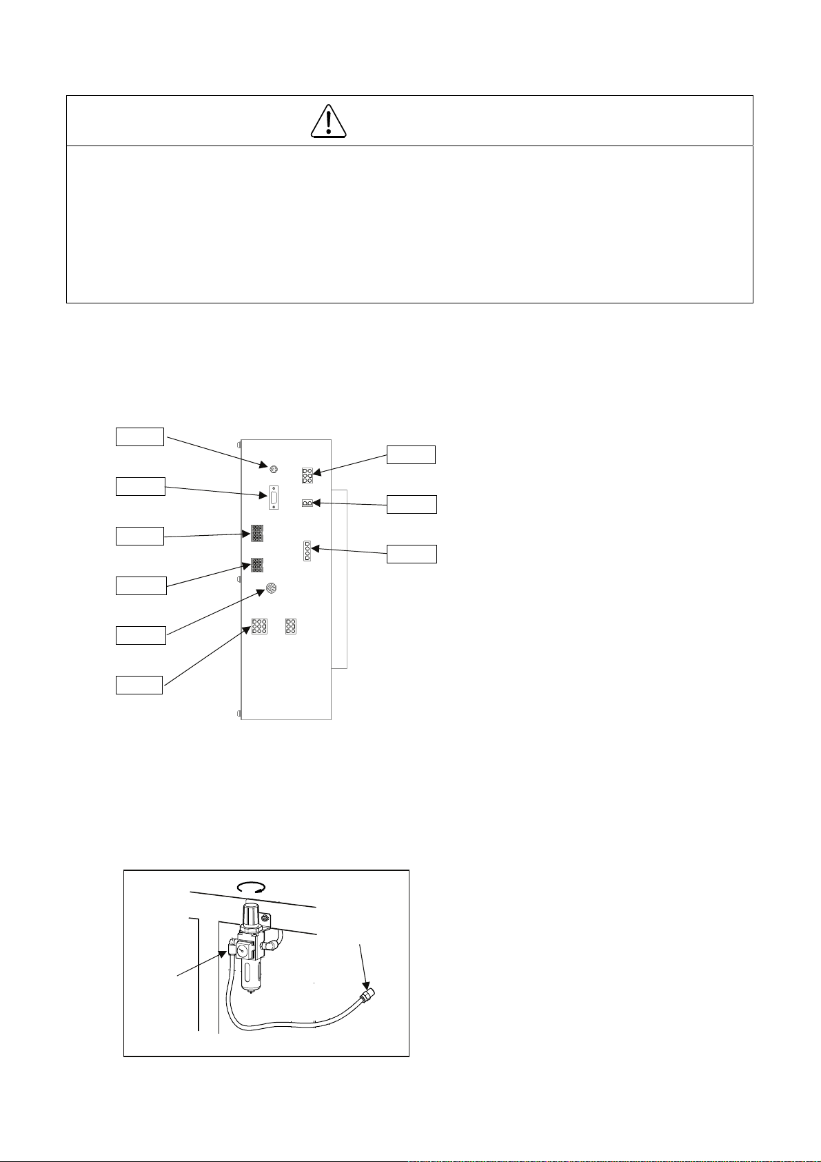
3-1. Installation of the foot switch
Connect the foot switch to the connector CON H.
The foot switch is enclosed in the accessory box.
CON A
CON E
CON F
CON G
CON H
CON J
CON B
CON C
CON D
CON A: Operation panel
CON B: Power supply
CON C: Various solenoid DC power
CON D: Spindle motor
CON E: Various solenoid
CON F: Spindle encoder
CON G: X-Y spindle encoder
CON H: Foot switch
CON J: X-Y spindle stepping motor
3-2. Connection of the air tube
Insert the one end of the air tube (8mm Diameter) into the intake air fitting of the filter regulator (No.1)
then, join the other end of the air tube with the suitable air coupling to be adopted with the air supply
source provided in your factory. One of the air couplings (No.2) is enclosed in the accessory box.
<1>
①
<2>
②
- 3 -
<1>: Intake air fitting
<2>: Air coupling
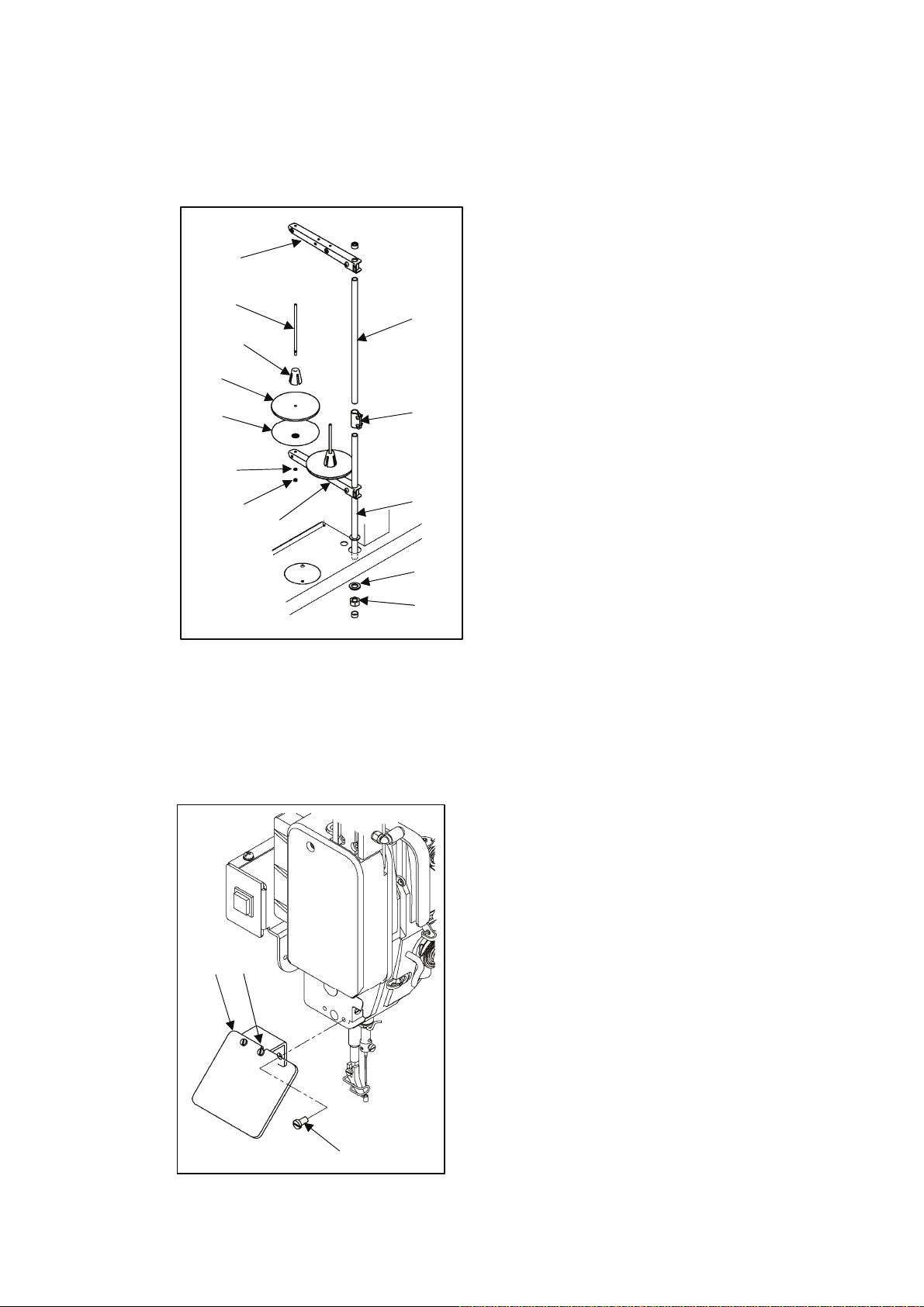
3-3. Installation of the thread stand
(1) Assemble the parts (No.1 to No.11) of the thread stand as shown on the figure.
(2) Fit the thread stand into the hole at the far right on the table stand with the nut (No.13) and the
washers (No.12).
<9>
<6>
<4>
<3>
<7>
<5>
<8>
<1>
<11>
<2>
<10>
<12>
<13>
<1>: Upper column pipe
<2>: Lower column pipe
<3>: Spool stand base (two stand bases)
<4>: Spool mat (two mats)
<5>: Spool holder (two holders)
<6>: Spool shaft (two shafts)
<7>: Spring washer (two washers)
<8>: Nut (four nuts)
<9>: Thread hunger
<10>: Spool holder
<11>: Column joint
<12>: Washer
<13>: Nut
3-4. Installation of the eye guard
(1) Loosen the screws (No.2) on the eye guard unit (No.1) then, mount the screws (No.3) to the flat place
of the sewing machine with the open guard.
(2) Return the open guard to the initial position then, tighten the screws (No.2).
<1>
<2>
<1>: Eye guard unit
<2>: Screw
<3>: Screw (two screws)
<3>
- 4 -
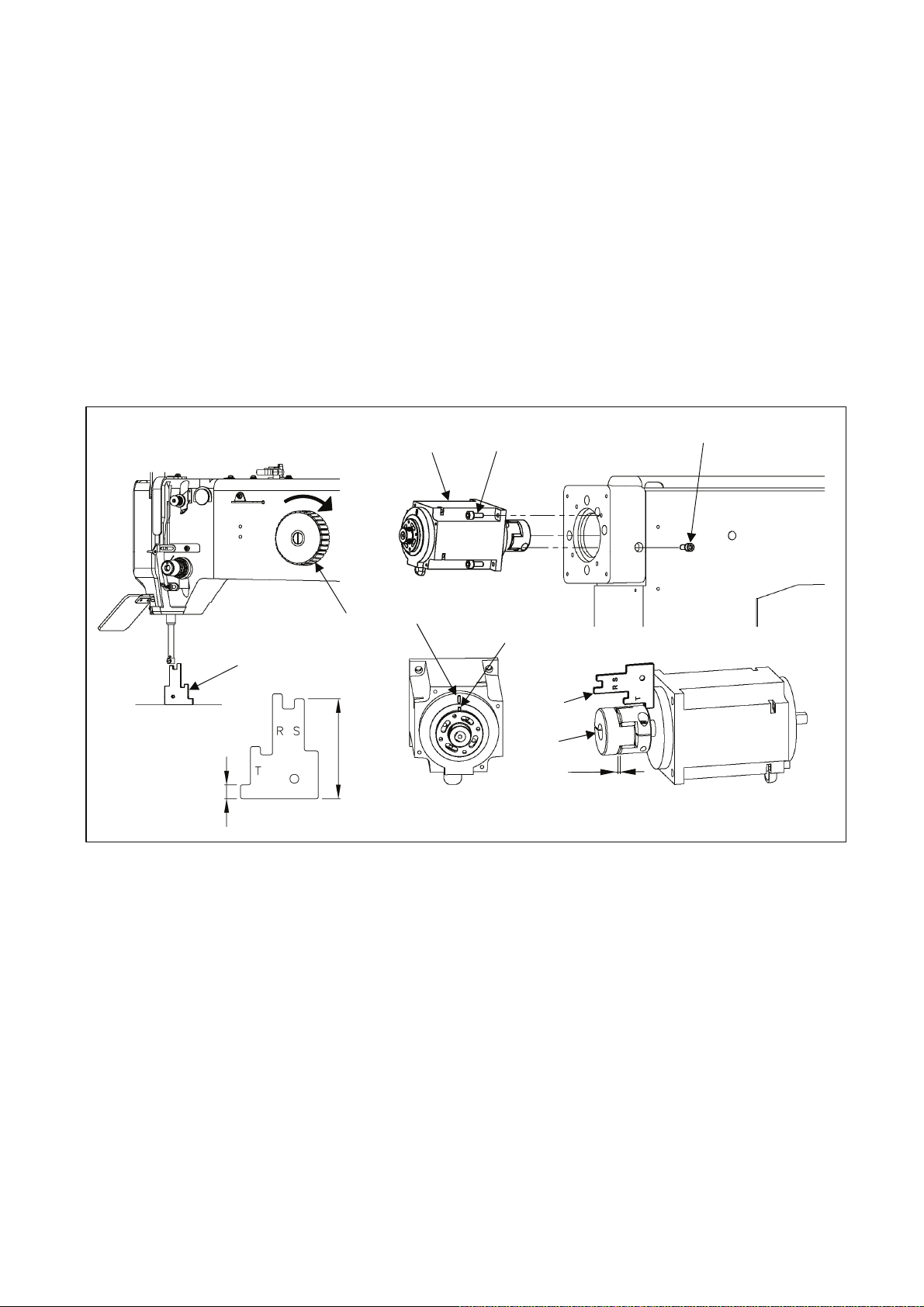
3-5. Installation of the spindle motor
(1) If the spindle motor (No.1) has been removed from the machine for the adjustment or the like, fix the
spindle motor as the procedure described below.
(2) Set the pin (No.3) position of the bushing to the motor mark (No.2).
(3) Adjust the clearance between the motor and the coupling (No.4). Use the part measuring 7mm on the
gauge (No.5). Position Bolt “A” (No.6) in the below described position when reinstalling the coupling to
the machine top shaft. Make sure the clearance of the coupling is from 2.0 to 3.2mm.
(4) Turn the pulley (No.8) in the direction of the arrow then, slip the gauge (No.5) in between the needle
bar and the needle plate. Use the part of S side (50.1mm) on the gauge.
(5) Be careful not to make the motor turn and fit the coupling to the upper shaft, and then tighten the bolt
A (No.6) first and the bolt B (No.7) second.
<1>
<7>
<6>
<5>
<8>
<2>
<3>
<5>
<4>
2.0~3.2mm
7
<1>: Spindle motor <2>: Motor mark <3>: Pin <4>: Coupling <5>: Gauge <6>: Bolt A
<7>: Bolt B <8>: Pulley
- 5 -
4. LUBRICATION
CAUTION
(1) Please make sure to turn power switch off before lubricating.
(2) Please pay attention that oil does not get on your skin or in your eyes as it may cause an inflammation.
(3) Please make sure to keep oil out of the reach of children who may drink oil by mistake.
[Notice] Please make sure to lubricate when operating for the first time after the installation. Also, please
make sure to check the amount of oil when the machine has not been used for a long time.
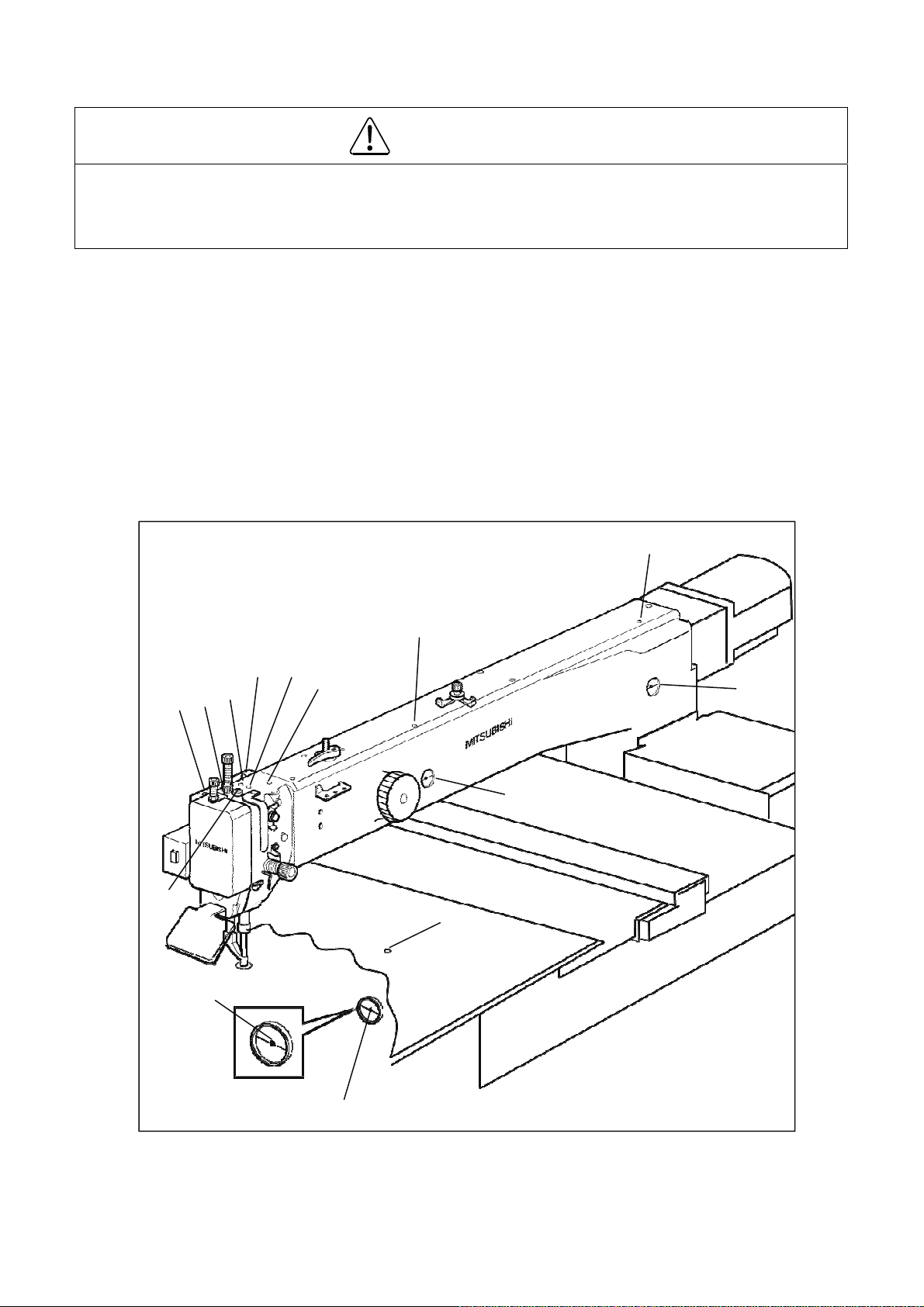
4-1. Filling the oil tank
Pour the oil through the oil hole (No.1 and 3) to the oil tank (No.2 and 4) on the machine arm. Pour
the oil hole (No.5) to the oil tank (No.6) on the machine bed. Please fill with the oil over level mark
(No.7) of the oil tank.
4-2. Oiling
Put some oil to the red marked oil holes (No.8 ~ 14).
<1>
<8>
<14>
<9>
<11>
<10>
<12>
<13>
<3>
<2>
<4>
<5>
<7>
<6>
- 6 -
5. PROPER OPERATION
5-1. Initial setting of the control box
When using the sewing machine for the first time, the model and the language of the sewing machine in
use have to be set.
Refer to the instructions in the paragraph “[6] Initial Setting of System (Model/language Setting)” in the
CONTROL UNIT technical manual.
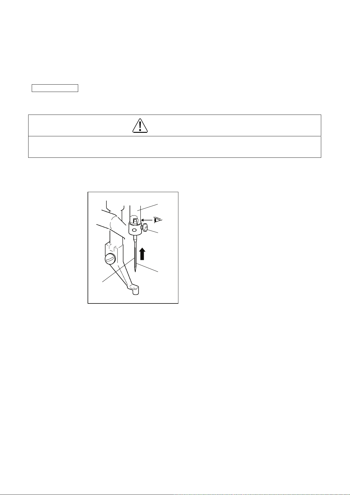
5-2. Installation of the needle
CAUTION
(1) Please make sure to turn the power switch off before installing or replacing needles.
(2) Please pay attention for the fingers not to be injured by the needle point.
(1) Loosen the set screw (No.1) then, insert a new needle (No.2) until the needle head is reached the end
of the hole of the needle bar (No.3).
(2) Tighten the set screw (No.1) with facing the needle groove (No.4) to the front.
<3>
<1>
<1>: Set screw
<2>: Needle
<3>: Needle bar
<4>: Needle groove
<2>
<4>
- 7 -
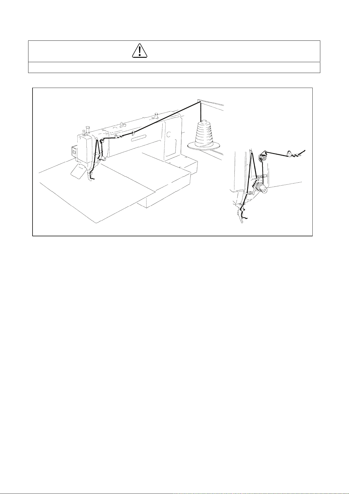
5-3. Threading the upper thread
CAUTION
(1) Please turn the power switch off when threading a needle.
Thread the upper thread as shown on the figure.
- 8 -
 Loading...