

Page 1

BeneVision TMS60
Telemetry Monitoring System
Service Manual
Page 2

Page 3

Intellectual Property Statement
SHENZHEN MINDRAY BIO-MEDICAL ELECTRONICS CO., LTD. (hereinafter called Mindray)
owns the intellectual property rights to this product and this manual. This manual may
refer to information protected by copyrights or patents and does not convey any license
under the patent rights of Mindray, nor the rights of others. Mindray does not assume any
liability arising out of any infringements of patents or other rights of third parties.
Mindray intends to maintain the contents of this manual as confidential information.
Disclosure of the information in this manual in any manner whatsoever without the
written permission of Mindray is strictly forbidden.
Release, amendment, reproduction, distribution, rent, adaptation and translation of this
manual in any manner whatsoever without the written permission of Mindray is strictly
forbidden.
, and are the registered trademarks or trademarks
owned by Mindray in China and other countries. All other trademarks that appear in this
manual are used only for editorial purposes without the intention of improperly using
them. They are the property of their respective owners.
This posting serves as notice under 35 U.S.C.§287(a) for Mindray patents:
http://www.mindrayna.com/patents.
For this manual, the issued Date is January 2019 (Version: 4.0).
© 2015-2019 Shenzhen Mindray Bio-Medical Electronics Co., Ltd. All rights reserved
WARNING
Federal Law (USA) restricts this device to sale by or on the order of a
physician or other practitioner licensed by U.S. state law to use or
order the use of this device..
NOTE
This manual describes all features and options. The equipment may not
have all of them. Contact Mindray service department for any questions.
BeneVision TMS60 Service Manual I
Page 4

Manufacturer’s Responsibility
Contents of this manual are subject to changes without prior notice.
All information contained in this manual is believed to be correct. Mindray shall not be
liable for errors contained herein nor for incidental or consequential damages in
connection with the furnishing, performance, or use of this manual.
Mindray is responsible for the effects on safety, reliability and performance of this
product, only if:
All installation operations, expansions, changes, modifications and repairs of
this product are conducted by Mindray authorized personnel;
The electrical installation of the relevant room complies with the applicable
national and local requirements;
The product is used in accordance with the instructions for use.
WARNING
This manual is for biomedical engineers or technicians responsible for
troubleshooting, repairing, and maintaining the telemetry monitoring
system.
II BeneVision TMS60 Service Manual
Page 5

Return Policy
In the event that it becomes necessary to return a unit to Mindray, follow the instructions
below.
1. Obtain a return authorization.
Contact the Mindray Service Department and obtain a Mindray Customer Service
Authorization Number. The Mindray Customer Service Authorization Number must
appear on the outside of the shipping container. Return shipments will not be accepted if
the Mindray Customer Service Authorization Number is not clearly visible. Please provide
the model number, serial number, and a brief description of the reason for return.
2. Freight policy
The customer is responsible for freight charges when this product is shipped to Mindray
for service (including any relevant customs fees or other freight related charges).
3. Return address
Please send the part(s) or equipment to the address offered by Customer Service
Department.
BeneVision TMS60 Service Manual III
Page 6

Contact Information
Manufacturer: Shenzhen Mindray Bio-Medical Electronics Co., Ltd.
Address: Mindray Building, Keji 12th Road South, High-tech Industrial
park, Nanshan, Shenzhen 518057,P.R.China
Website: www.mindray.com
E-mail Address: service@mindray.com
Tel : +86 755 81888998
Fax: +86 755 26582680
Distributor: Mindray DS USA, Inc.
Address: 800 MacArthur Boulevard, Mahwah, New Jersey 07430, USA
Tel : 1.800.288.2121, 1.201.995.8000
Website: http://www.mindraynorthamerica.com/
IV BeneVision TMS60 Service Manual
Page 7

Contents
1 Safety .................................................................................................................. 1-1
1.1 Safety Information ...................................................................................................................... 1-1
1.1.1 Warnings ........................................................................................................................... 1-2
1.1.2 Cautions ............................................................................................................................ 1-2
1.1.3 Notes ................................................................................................................................. 1-2
1.2 Equipment Symbols ................................................................................................................... 1-3
2 Principles .................................................................................................................... 2-1
2.1 System Operating Principle ...................................................................................................... 2-1
2.2 Hardware Operating Principles ............................................................................................... 2-2
2.2.1 Transmitter Principle ..................................................................................................... 2-2
2.2.2 Overview .......................................................................................................................... 2-2
2.2.3 Receiver ............................................................................................................................ 2-3
2.2.4 Central Monitoring System (CMS) ............................................................................. 2-5
2.2.5 Central Charger ............................................................................................................... 2-5
2.3 Software Principles ..................................................................................................................... 2-8
2.3.1 Transmitter Software System ...................................................................................... 2-8
2.3.2 Receiver System Software ............................................................................................ 2-9
3 Receiver Physical Views .............................................................................................. 3-1
3.1 Front View ..................................................................................................................................... 3-1
3.2 Rear View ....................................................................................................................................... 3-2
3.3 Restoring Latest Configuration Automatically .................................................................... 3-3
4 BP10 Physical Views ................................................................................................... 4-1
4.1 Front View ..................................................................................................................................... 4-1
4.2 Side View ....................................................................................................................................... 4-2
4.3 Top Vie w ........................................................................................................................................ 4-3
5 Central Charger Physical Views .................................................................................. 5-1
5.1 Front View ..................................................................................................................................... 5-1
5.2 Rear View ....................................................................................................................................... 5-1
6 Maintenance ............................................................................................................... 6-1
6.1 Recommended Maintenance and Test Frequency ............................................................. 6-2
6.2 Parameter Tests ............................................................................................................................ 6-3
6.2.1 ECG Test s .......................................................................................................................... 6-3
6.2.2 Resp Test ........................................................................................................................... 6-4
6.2.3 SpO2 Tes t ........................................................................................................................... 6-5
6.2.4 NIBP Tests ......................................................................................................................... 6-6
6.3 Miscellaneous Tests .................................................................................................................... 6-9
BeneVision TMS60 Service Manual 1
Page 8

6.3.1 Visual Inspection ............................................................................................................ 6-9
6.3.2 Power-On Te st ................................................................................................................. 6-9
6.3.3 Nurse Call Test ................................................................................................................. 6-9
6.3.4 Electric Safety Test....................................................................................................... 6-10
6.3.5 Network Print Test ....................................................................................................... 6-10
6.3.6 Battery Check ............................................................................................................... 6-10
6.3.7 Tests in Service Menu ................................................................................................. 6-10
7 Service Menu .............................................................................................................. 7-1
7.1 Entering the Service Menu ....................................................................................................... 7-1
7.2 Performing Software Update ................................................................................................... 7-1
7.3 Service Log ................................................................................................................................... 7-1
7.4 Fa cto ry Test ................................................................................................................................... 7-1
7.4.1 Device Test ....................................................................................................................... 7-1
7.4.2 Screen Test ....................................................................................................................... 7-2
7.4.3 Tou ch Scr een Te st ........................................................................................................... 7-2
7.4.4 Keys Test ........................................................................................................................... 7-2
7.4.5 Sound & Light Test ......................................................................................................... 7-3
7.4.6 USB Interface Test .......................................................................................................... 7-3
7.4.7 System Watchdog Test .................................................................................................. 7-3
7.4.8 MO Module Watchdog Test ......................................................................................... 7-3
7.4.9 Bluetooth Module Test.................................................................................................. 7-4
7.4.10 Processing Method ...................................................................................................... 7-4
7.5 Checking System Software Version ........................................................................................ 7-5
8 Troubleshooting ......................................................................................................... 8-1
8.1 Telemetry Monitoring System Problems ............................................................................... 8-1
8.1.1 Troubleshooting Tools .................................................................................................. 8-1
8.1.2 Technical Alarm Messages ........................................................................................... 8-1
8.1.3 Error Codes ...................................................................................................................... 8-3
8.1.4 Other Failures .................................................................................................................. 8-7
8.1.5 Failure Examinations ..................................................................................................... 8-9
8.2 Central Charger Problems ...................................................................................................... 8-25
9 Parts ........................................................................................................................... 9-1
9.1 Transmitter (P/N 115-029485-00/115-047566-00).............................................................. 9-1
9.1.1 Exploded View of Main Unit ........................................................................................ 9-1
9.2 Receiver (P/N 115-029486-00) ................................................................................................. 9-5
9.2.1 Exploded View of Receiver ........................................................................................... 9-5
9.2.2 Front Cover Assembly of Receiver ............................................................................. 9-8
9.2.3 Power Assembly of Receiver ....................................................................................... 9-9
9.2.4 Amplifying and Branching Assembly of Receiver (P/N 0152-30-39691) ...... 9-10
9.2.5 Active Antenna (P/N 115-059711-00) .................................................................... 9-11
9.2.6 4-Channel Receiver Module Assembly (P/N 115-029487-00) .......................... 9-12
9.3 Power Injector (P/N 115-035637-00) ................................................................................... 9-13
9.4 Signal Switching Box (P/N 115-020216-00) ....................................................................... 9-14
2 BeneVision TMS60 Service Manual
Page 9

9.5 BP 10 (P/N 115-047557-00) .................................................................................................... 9-15
9.5.1 BP10 Front Housing Assembly................................................................................. 9-15
9.5.2 BP10 Rear Housing Assembly .................................................................................. 9-16
9.5.3 BP10 Main Unit ............................................................................................................ 9-17
9.6 Exploded View of Central Charger (PN:115-030108-00) ................................................ 9-18
9.7 Miscellaneous: .......................................................................................................................... 9-19
A Electrical Safety Inspection ....................................................................................... A-1
A.1 Power Cord Plug ........................................................................................................................ A-1
A.2 Device Enclosure and Accessories ........................................................................................ A-2
A.3 Device Labeling ......................................................................................................................... A-2
A.4 Scheduled Electrical Safety Inspection ............................................................................... A-2
A.5 Electrical Safety Inspection after Repair ............................................................................. A-2
A.6 Electrical Safety Inspection Form ......................................................................................... A-3
BeneVision TMS60 Service Manual 3
Page 10

This page intentionally left blank.
4 BeneVision TMS60 Service Manual
Page 11

1 Safety
1.1 Safety Information
WARNING
Indicates a potential hazard or unsafe practice that, if not avoided, could
result in death or serious injury.
CAUTION
Indicates a potential hazard or unsafe practice that, if not avoided, could
result in minor personal injury or product/property damage.
NOTE
Provides application tips or other useful information to ensure that you
get the most from your product.
BeneVision TMS60 Service Manual 1-1
Page 12

1.1.1 Warnings
WARNING
There is high voltage inside the system. Never disassemble the system
before it is disconnected from the AC power source.
The system must be connected to a properly installed power outlet with
protective earth contacts only. If the installation does not provide for a
protective earth conductor, disconnect it from the power line.
To completely disconnect the power supply, unplug the power cord.
To avoid the electric shock, disassemble the central charger after the
central charger is disconnected from the AC power source for five minutes
la ter.
Dispose of the package material, observing the applicable waste control
regulations and keeping it out of children’s reach.
1.1.2 Cautions
CAUTION
Make sure that no electromagnetic radiation interferes with the
performance of the system when preparing to carry out performance tests.
Mobile phone, X-ray equipment or MRI devices are a possible source of
interference as they may emit higher levels of electromagnetic radiation.
Before connecting the system to the power line, check that the voltage and
frequency ratings of the power line are the same as those indicated on the
system’s label or in this manual.
Protect the system from damage caused by drop, impact, strong vibration
or other mechanical force during servicing.
1.1.3 Notes
NOTE
Refer to Operator’s Manual for detailed operation and other information.
1-2 BeneVision TMS60 Service Manual
Page 13

1.2 Equipment Symbols
See TMS60 Telemetry Monitoring System/TM80 Telemetry Monitor Operator’s Manual
for information about the symbols used on this product and its packaging.
BeneVision TMS60 Service Manual 1-3
Page 14

This page intentionally left blank.
1-4 BeneVision TMS60 Service Manual
Page 15
2 Principles
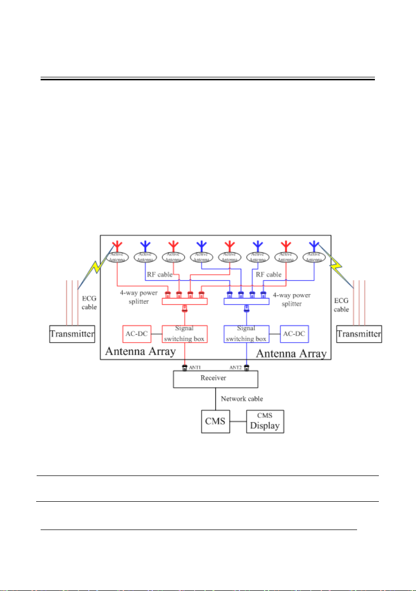
2.1 System Operating Principle
TMS60 is a digital telemetry monitoring system consisting of the transmitter (TD60), the
receiver (RC60), the antenna array. The transmitter sends the patient’s physiological
information to the receiver, which then transmits the information to the Central
Monitoring System (CMS) for analysis, displaying, storage and printing. The transmitter is
attached to the patient, whereas the receiver is used together with the CMS. TMS60
telemetry monitoring system is intended to monitor and display a fixed set of parameters
including ECG, Resp, SpO
module, SpO
The following is a simple illustration:
module, and NIBP module are optional.
2
, N IB P, HR and PR under hospital environments. The Resp
2
Figure 2-1 TMS60 Telemetry Monitoring System Diagram
NOTE
The distance between the TD60 and the antenna should be at least one
meter.
BeneVision TMS60 Service Manual 2-1
Page 16
WMTS IC
TCXO
12.8
M
LDO
Match
LPF
PLL
MCU
ECG circuit
SpO2
connector
ECG
leadwire
Externally
connecting with
SpO2
module
Power
Circuit
Display and
Control Module
Bluetooth
module
Antenna
NIBP module
2.2 Hardware Operating Principles
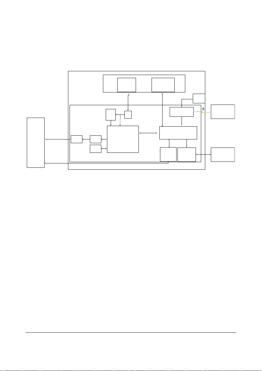
2.2.1 Transmitter Principle
Figure 2-2 Transmitter Principle Diagram
2.2.2 Overview
The transmitter mainly consists of the MCU, ECG circuit, SpO2 connector, WMTS circuit,
Bluetooth module, Power Circuit, and Display and Control Module.
The ECG circuit provides the amplified ECG signals, which supports 3-lead and 5-lead
modes.
SpO
module is externally connected to the transmitter.
2
WMTS circuit is to send ECG data, SpO2 data and status information out .The shielding
layer of the ECG lead is the transmitter antenna.
Bluetooth module is used to transfer configuration between the transmitters.
The Display and Control Module consists of a LCD, a touch screen, a LED indicator, a
speaker, and three keys. It is used to display ECG, SpO
etc, and allow users to control transmitter.
2-2 BeneVision TMS60 Service Manual
waveforms and transmitter status,
2
Page 17
The MCU circuit is the core of the transmitter, enabling the following functions:
Button signal detection
SpO
connector
2
Status detection, such as ECG overload detection, lead off detection, PACE
detection, etc.
ECG data processing
MWTS circuit control and Baseband signal generation
Bluetooth module control
2.2.3 Receiver
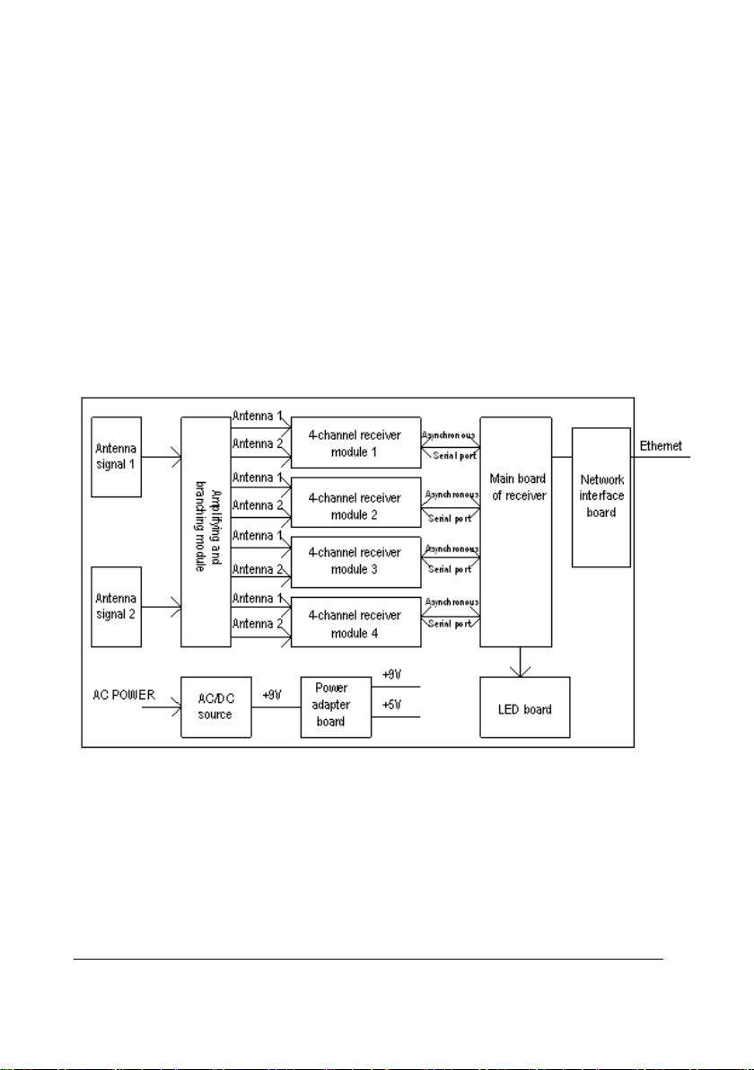
2.2.3.1 Principle Diagram
Figure 2-3 Receiver Principle Diagram
The receiver comprises the AC/DC power source, power adapter board, amplifying and
branching module, 4-channel receiver, LED board, main control board and network
interface board.
BeneVision TMS60 Service Manual 2-3
Page 18

2.2.3.2 AC/DC Source
The AC/DC source is to convert the externally inputted AC source into a 9V DC by means
of isolation. The inputted AC voltage range is from 90V to 264V, and the outputted
voltage/current is 9V/6.5A.
2.2.3.3 Power Adapter Board
The power adapter board is to drop the 9V DC coming from the AC/DC source to a 5V DC
and then output it with the 9V DC.
2.2.3.4 Amplifying and Branching Module
The amplifying and branching module is to amplify, filter and branch RF signals. The
module allows two amplifying, filtering & branching circuits with circuit parameters in full
symmetry. Each circuit amplifies, filters and branches the RF signals received by its
corresponding antenna and then outputs 4 channels of RF signals. Therefore, there are a
total of 8 channels of RF signals, which are then sent to the 4-channel receiver for
processing. The 9V DC linearly drops down to an 8V DC, which then goes to the
amplifying and branching module. The antenna array is shared by all receiving modules.
Therefore, in order to compensate for the branching attenuation of the signal, a LNA (low
noise amplification) is added before the branch divider. Besides, to avoid that the LNA is
blocked by strong out-band signal interference, filtering circuits shall be added in front of
and behind the LNA.
2.2.3.5 4-Channel Receiver
The 4-channel receiver divides the two channels of antenna signals coming from the
amplifying and branching module into four channels of RF signals through the 4-channel
branch divider. The MCU of the 4-channel receiving board will estimate the received
signal strength (RSSI) and then select the corresponding antenna signals through the
antenna switch. The selected signals will be respectively sent to the receiving modules for
filtering, amplifying, mixing, filtering and demodulating. The demodulated 4-channel
analog signals will then be sent to the MCU system for clock and data regenerating. The
regenerated data is packed by CPU and then delivered via the asynchronous serial port to
the main control board for processing. The 9V DC linearly drops down to an 8V DC, which
is then stabilized into a 5V and a 3.5 V supplying power for the 4-channel receiver.
2.2.3.6 Main Control Board
After receiving the data coming from the 4-channel receiving board, the main control
board will pack them and then delivers them to theCMS through the Ethernet. The
speaker of the main control board will give a short beep when the initialization is over,
and will beep continuously when an initialization failure or a hardware fault occurs.
2-4 BeneVision TMS60 Service Manual
Page 19
1
2.2.3.7 LED Board
The LED board has two green LEDs, respectively indicating the power status and the
communication status of the receiving module.
2.2.3.8 Network Interface Board
The interface between the main control board and Ethernet consists of the network
isolating transformer and interface connector.
2.2.4 Central Monitoring System (CMS)
BeneVision Central Monitoring System comprises powerful system software and
high-performance computer components. It constructs a monitoring network by
connecting monitors and telemetry transmitters. By collecting, processing, analysing and
outputting the information coming from monitors and telemetry transmitters, the CMS
can achieve centralized monitoring over multiple patients so as to greatly promote the
efficiency and quality of the monitoring work.
The CMS is capable of connecting up to 32 telemetry transmitters.
2.2.5 Central Charger
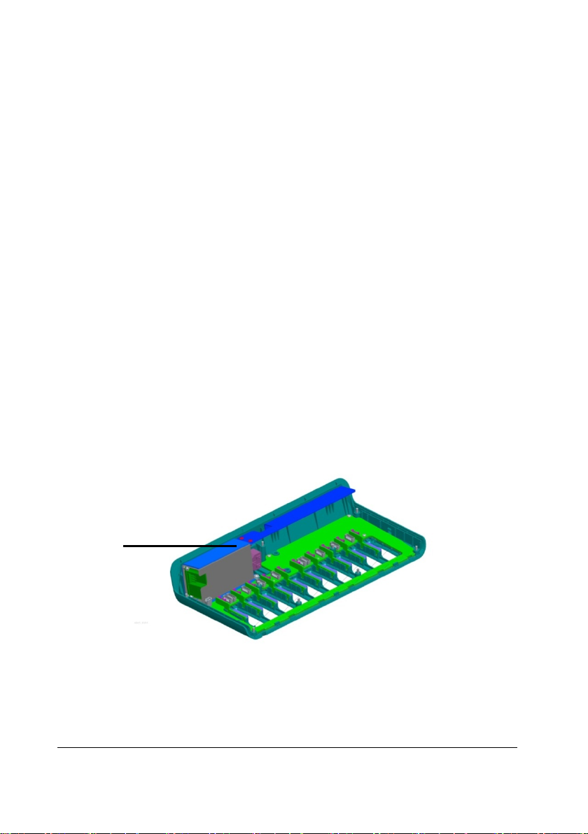
The central charger inner structure consists of three boards, as shown in Figure 2-4:
BeneVision TMS60 Service Manual 2-5
Page 20
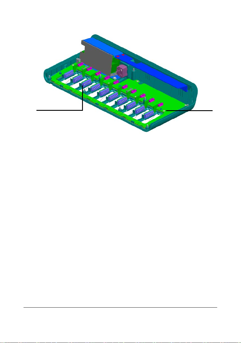
2
3
Figure 2-4 Central Charger Inner Structure
1. AC-DC board (one)
Switching the AC circuit to the DC circuit.
2. Main board (one)
Including the charge circuit, MCU, and LED indicator.
3. Battery interface board (10)
Switching the circuit from the battery contact terminal to the main board.
Three kinds of wires connect with those boards:
AC-DC socket + wire (P/N 0651-20-76879)
The wire connects the AC socket and the AC-DC board.
Main board wire (P/N 009-003327-00)
The wire connects the AC-DC board and the main board.
Battery interface board wires (10) (P/N 009-003325-00)
The wires connect the main board and the battery interface boards.
2-6 BeneVision TMS60 Service Manual
Page 21
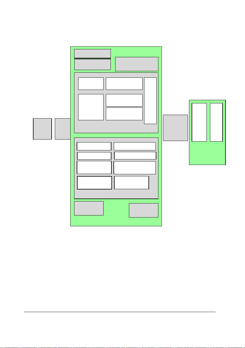
Main board
AC-DC socket
MCU power supply
circuit
Charge Circuit (10)
EN Circuit
Charge
voltage
selecting
circuit
Charge current
selecting circuit
NTC detection
circuit
Battery switch board
socket
MCU (10)
LED control
Burning upgrade
I2C access
EN control
Charge voltage
control
Charge current
control
Battery-LED
circuit (10)
AC-LED
circuit
AC-DC
board
Main
board
wire
Battery
interface
board wire
(10)
Battery
interface board
(10)
Battery interface
socket Battery contact
terminal
DC-DC
MOS Switch
circuit
voltage AD
detect
MOS switch
control
BeneVision TMS60 Service Manual 2-7
Figure 2-5 Central Charger Hardware Boards and Wires
Page 22
Transmitter Software
System
ECG Circuit
SpO2 Module
Display Unit
Toucher
Power Hard Key
Menu Hard Key
Nurse Call Hard Key
Patient
Signal
User
Serial Port
Speaker
Alarm Light
Battery
Central Monitoring
System
RF Module
2.3 Software Principles
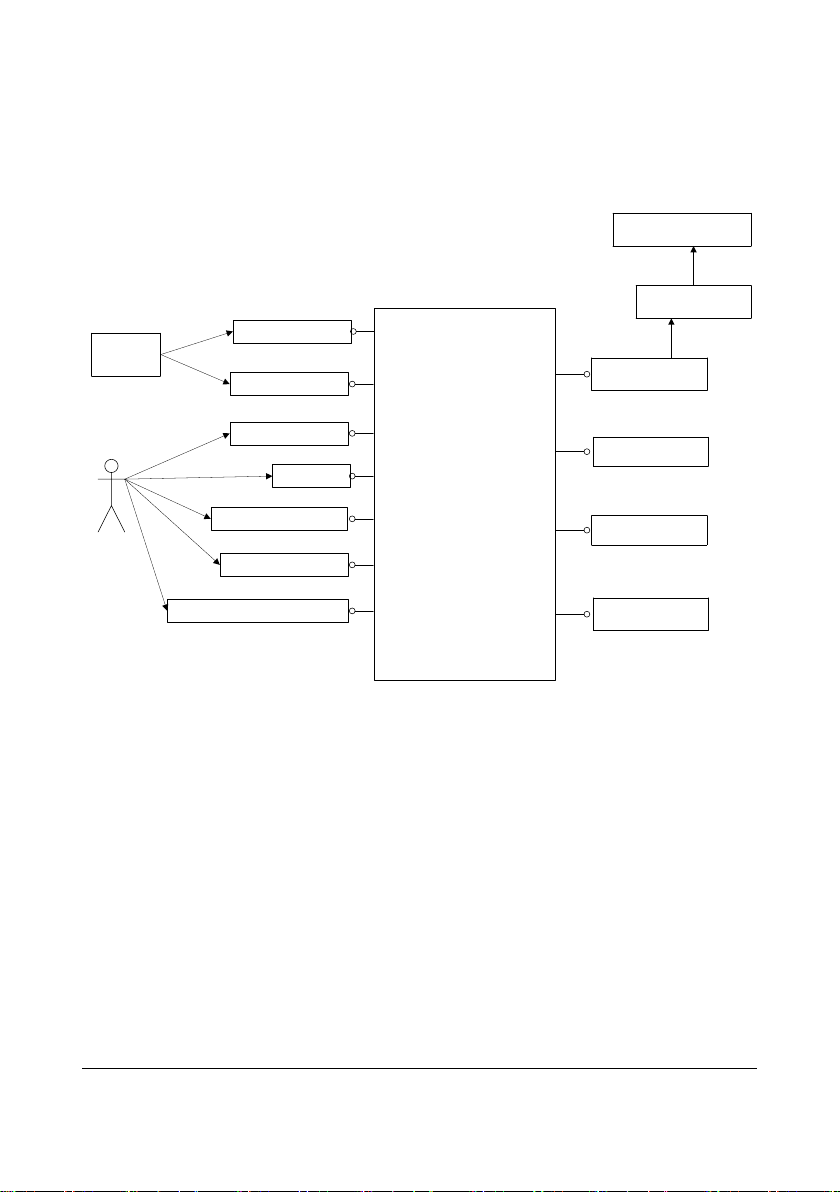
2.3.1 Transmitter Software System
2.3.1.1 Overview
Figure 2-6 Interfacing Diagram between the Transmitter Single-Chip Software and
Peripherals
Inside the solid frame is the transmitter software system (hereinafter called the software
system), and outside the solid frame are the inputs and outputs of the software system.
The patient’s ECG data are inputted into the software system by means of sampling.
The external SpO
and the collected SpO
CMS and external SpO
serial port. The user commands and online upgrade files of the transmitter software are
inputted into the software system through this serial port.
Patient calls can be inputted into the software system through the nurse call button. The
pa t i e nt ’s ECG and SpO
by the software system and then transmitted to the RF module. In addition, the indicator
and speaker are also controlled by the software system.
module communicates with the transmitter through the serial port,
2
data are inputted into the software system via the serial port. The
2
module communicate with the transmitter through the same
2
parameter signals and the transmitter’s status data are processed
2
2-8 BeneVision TMS60 Service Manual
Page 23
2.3.1.2 Transmitter System Task
The transmitter collects the patient’s ECG and SpO2 signals, and then detects the pace
pulse, SpO
and other status information in them by amplifying and digitalizing them,
2
and finally sends the detected information to the receiver through wireless channels.
The transmitter supports the auto detection of 3-lead or 5-lead leadwire, lead off
detection and PACE detection. It also supports the external SpO
connector, through which the CMS can perform the parameter configuration and
SpO
2
module through the
2
online software upgrade to the transmitter.
The transmitter also enables these functions including battery voltage detection,
hardware button detection including the Power On/Off and Display On/Off button ,
Nurse Call button , Main menu/Main screen button . Besides, it supports
audible and visual alarms and enables the standby mode, sleep mode, and lock screen
mode.
2.3.2 Receiver System Software
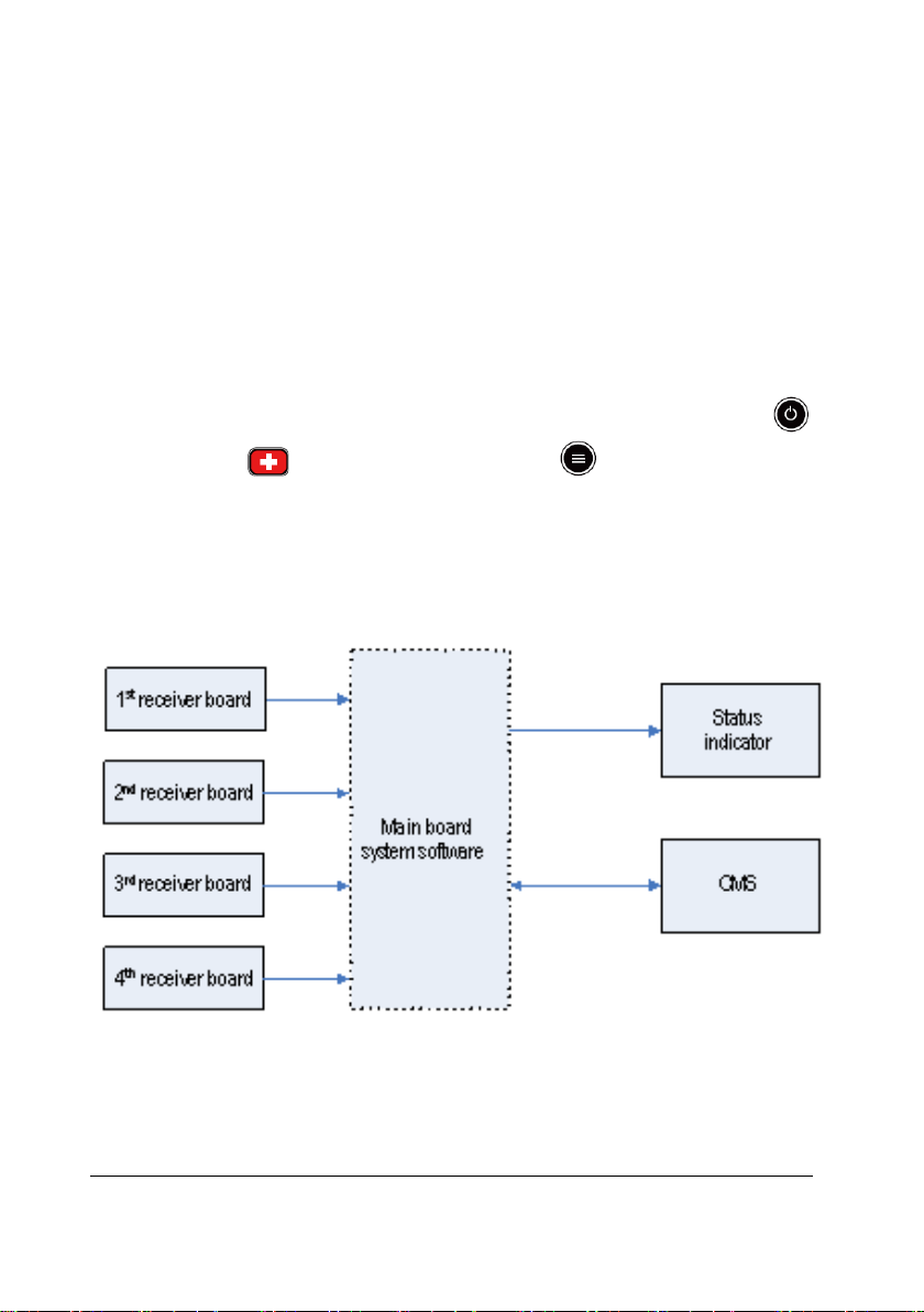
2.3.2.1 Overview
Figure 2-7 Receiver system software diagram
Inside the dashed frame is the system software of the main control board (hereinafter
called the software system), and outside the dashed frame is the inputs and outputs of
the software system. The data coming from the 4-channel receiver are sent to the
software system through the serial port.
BeneVision TMS60 Service Manual 2-9
Page 24
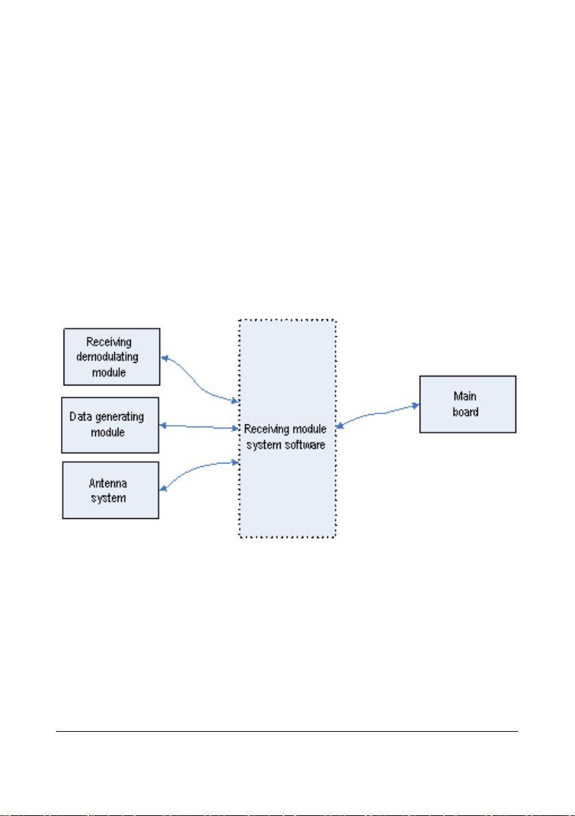
The main control board and receiver controller communicate through the serial port. The
main control board directly controls the LED indicator through the I/O port and
communicates with the CMS through the Ethernet.
2.3.2.2 Receiver System Task
The receiver receives data from boards, descrambles data, analyses the integrity of data,
generates relevant alarm messages and sends them together with data to the CMS.
Through the receiving controller, the receiver obtains and controls the operating status of
the receiving demodulator, including the operating frequency and signal strength of the
demodulator. After detecting the operating status, the receiver will give prompt
information through the communication status indicator.
2.3.2.3 Overview of the 4-Channel Receiver Software
Figure 2-8 Diagram for the 4-Channel Receiver Software
Inside the dashed frame is the receiving module control software (hereinafter call
software system), and outside the dashed frame are the inputs and outputs of the
software system. Through the serial port and signal line, the software system
communicates with the receiving demodulator, resolves the data coming from the
data-generating module and controls the antenna system via switch. Besides, it also
communicates with the main control board via the serial port.
2-10 BeneVision TMS60 Service Manual
Page 25

2.3.2.4 4-Channel Receiver Software Task
The 4-channel receiver mainly undertakes the following tasks:
Recover and resolve the wireless transmission space protocol;
Configure frequency for the 4-channel receiver on the receiving board;
Collect the RSSI from the 4-channel receiver on the receiving board;
Select antenna according to the received signal strength;
Collect the status information of the 4-channel receiver on the receiving board;
Carry out the communication with the main control board.
BeneVision TMS60 Service Manual 2-11
Page 26

This page intentionally left blank.
2-12 BeneVision TMS60 Service Manual
Page 27
3 Receiver Physical Views
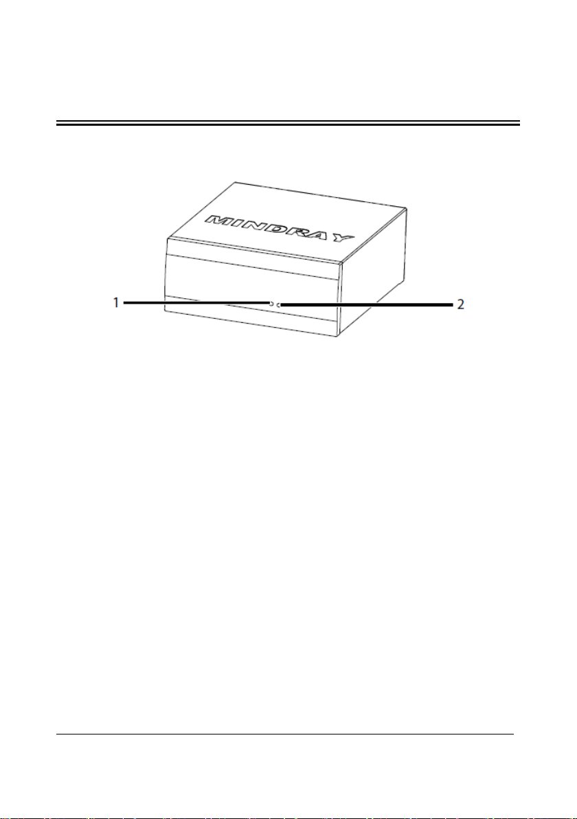
3.1 Front View
Figure 3-1 Receiver Front View
1. Communications indicator
Flashes periodically: communications is occurring.
On: communications is not occurring.
Off: there is a startup failure or hardware failure.
2. Power indicator
On: the receiver is powered on.
Off: the receiver is powered off.
BeneVision TMS60 Service Manual 3-1
Page 28

3.2 Rear View
Figure 3-2 Receiver Rear View
1. Antenna connectors
The receiver has two antenna connectors. Each connector connects an antenna
cable.
2. Power switch
Place the switch to “┃” to turn the receiver on. Place the switch to “〇” to turn
the receiver off.
3. Fuse holder
You can open the cover to replace the fuse.
4. AC power input connector
5. Equipotential grounding terminal
When the receiver and other device are to be used together, their equipotential
grounding terminals should be connected together to eliminate the potential
difference.
6. Network connector
A standard RJ45 connector that connects the receiver to the central monitoring
system.
3-2 BeneVision TMS60 Service Manual
Page 29

WARNING
Only use the approved power cord with the grounded mains plug to firmly
connect the receiver to a grounded AC mains socket. Never refit the mains
plug to fit an ungrounded AC mains socket.
Do not use the Multiple Portable Socket Outlets (MPSO) or AC mains
extension cords. Use an IEC 60601-1 approved isolation / separation
transformer, otherwise, it may result in leakage current. Insure that the
sum of the individual ground leakage currents does not exceed the
allowable limits.
3.3 Restoring Latest Configuration Automatically
To prevent the changes from losing in case of a sudden power failure, the device, such as
the receiver or the BeneVision CMS, stores the configuration in real time. The saved
configuration is the latest configuration.
The device restores the latest configuration if it restarts within 60 seconds after the power
failure. And the device will restore the default configuration rather than the latest
configuration if it restarts 120 seconds after the power failure. The device may load either
the latest configuration or the default configuration if it restarts from 60-120 seconds
after the power failure.
BeneVision TMS60 Service Manual 3-3
Page 30

This page intentionally left blank.
3-4 BeneVision TMS60 Service Manual
Page 31

1 7 6 5 4
2
3
4 BP10 Physical Views
4.1 Front View
1. Display
2. Confirmation key
When the desired option is highlighted, press this key to select or activate the
corresponding function.
3. Main menu key
Press this key to turn to the main menu.
4. NIBP start/stop key
When NIBPmeasurement is in process, press this key to stop the
proceeding NIBP measurement.
When NIBP measurement is not performed, press this key to start an NIBP
measurement.
5. Down key
Press this key to move down along the column of menu options or configuration
choices.
BeneVision TMS60 Service Manual 4-1
Page 32

1 1 2
3
6. Return key
Press this key to return to the previous menu and save the settings.
Press this key to switch between two main screens.
7. Up key
Press this key to move up along the column of menu options or configuration
choices.
4.2 Side View
1. Power On/Off key
When BP10 is powered off, press this key to turn BP10 on.
When BP10 is powered on, press and hold this key to display the power off
confirmation menu.
If the screen display is on, press this key to turn the display off.
2. Mindray Patient Area Network (MPAN) key
When BP10 is disconnected from the MPAN, press this key to begin the
bluetooth pairing process.
When BP10 is connected with the MPAN , press this key to unpair any
connected bluetooth devices.
You can also set up the MPA N communication in the main menu.
3. USB port
This port is used for software upgrade.
4-2 BeneVision TMS60 Service Manual
Page 33

NIBP cuff connector: connect the NIBP hose.
4.3 Top Vie w
For further details about the BP10 NIBP module, refer to the BP10 NIBP Module
Operator’s Manual (P/N 046-011008-00).
BeneVision TMS60 Service Manual 4-3
Page 34

FOR YOUR NOTES
4-4 BeneVision TMS60 Service Manual
Page 35

1
5 Central Charger Physical Views
5.1 Front View
Figure 4-1 Central Charger Front Vi ew
1. Charging slot
2. AC power indicator
Off: No AC power supply connected, or the AC-DC board is abnormal.
Green: AC power supply is connected.
3. LED indicators: indicates the charging status for the corresponding charging slot.
5.2 Rear View
Figure 4-2 Central Charger Rear View
1. AC power socket
For further details about the central charger such as how to mount the central charger
and how to charge and remove batteries, refer to the BeneVision Central Charger
Operator’s Manual (P/N 046-007059-00).
BeneVision TMS60 Service Manual 5-1
Page 36

This page intentionally left blank.
5-2 BeneVision TMS60 Service Manual
Page 37

6 Maintenance
To ensure that the telemetry monitoring system always functions normally, qualified
service personnel should perform regular inspection, maintenance and test. This chapter
provides a checklist of the testing procedures for the telemetry monitoring system with
recommended test equipment and frequency. The service personnel should perform the
testing and maintenance procedures as required and use appropriate test equipment.
The testing procedures provided in this chapter are intended to verify that the telemetry
monitoring system meets the performance specifications. If the telemetry monitoring
system fails to perform as specified in any test, repairs or replacement must be done to
correct the problem. If the problem persists, contact our Customer Service Department.
CAUTION
All tests should be performed by qualified service personnel only.
Care should be taken to change the settings in the Maintenance menu to
avoid loss of data.
Service personnel should acquaint themselves with the test tools and
make sure that test tools and cables are applicable.
BeneVision TMS60 Service Manual 6-1
Page 38

Visual inspection
When first installed or reinstalled.
1. When first installed or reinstalled
transmitter components
Performance test
Calibration
Pressure check
Leakage test
1. After the transmitter or central charger
as needed
1. When first installed.
replaced.
1. When first installed.
2. Whenever a battery is replaced.
Once every two months or when the
noticeably shorter.
6.1 Recommended Maintenance and Test Frequency
Check/Maintenance Item Frequency
Power-on test
ECG test
Resp test Performance test
SpO2 test
NIBP test
Nurse call test
Electrical safety tests
Network print test
Functionality test
Battery check
Performance test
2. Following any repairs or replacement of
1. If the user suspects that the measurement
is incorrect.
2. Following any repairs or replacement of
relevant module.
3. At least once every two years.
Note: NIBP test should be performed at least
once a year.
If the user suspects that the measurement is
incorrect.
2. Performed at least once every two years or
2. Whenever the printer is serviced or
lithium-ion battery’s run time becomes
falls off.
6-2 BeneVision TMS60 Service Manual
Page 39

6.2 Parameter Tes ts
6.2.1 ECG Tests
6.2.1.1 ECG Performance Test
Tool required:
Medsim 300B patient simulator recommended
Follow this procedure to perform the test:
1. Connect the patient simulator with the ECG module using an ECG cable.
2. Set the patient simulator as follows: ECG sinus rhythm, HR=80 bpm with the
amplitude as 1mV.
3. Check the ECG waves are displayed correctly without noise and the displayed HR
value is within 80±1 bpm.
4. Disconnect each of the leads in turn and observe the corresponding lead off
message displayed on the screen.
5. Set that the simulator outputs paced signals and set
Check the pace pulse marks on the transmitter’s screen.
6.2.1.2 ECG Calibration
The ECG signal may be inaccurate due to hardware or software problems. As a result, the
ECG wave amplitude becomes greater or smaller.
Tool required:
Vernier caliper
To verify the ECG waveform amplitude:
1. In the main menu, select Parameter Setup.
2. Select ECG.
3. Set Filter to Monitor.
4. Return to the main menu and select Maintenance.
5. Input the maintenance passcode.
6. Tap Accept.
7. In the Maintenance menu, select General.
8. Enable Calibrate ECG. A square wave appears on the screen and the message ECG
Calibrating is displayed in the technical alarm area of the transmitter’s screen.
Compare the amplitude of the square wave with the wave scale. The difference
should be within 5%.
9. After completing the verification, disable Calibrate ECG. If necessary, you can print
out the square wave and wave scale through the recorder and then measure the
difference.
Paced to Yes on the transmitter.
BeneVision TMS60 Service Manual 6-3
Page 40

6.2.2 Resp Test
6.2.2.1 Enabling Resp Functionality
Before performing the Resp performance test, you need to enable the Resp functionality.
Follow this procedure to enable the Resp functionality:
1. After powering on the TD60, press to enter the main menu of the transmitter.
2. Select Maintenance→input the maintenance passcode→tap Accept→select
Service.
3. Input the passcode.
4. Tap Accept.
5. Enable Support Resp.
6. Return to the main menu.
7. Select Maintenance→input the maintenance passcode→tap Accept→select
General.
8. Enable Resp.
6.2.2.2 Resp Performance Test
Tools required:
Medsim300B patient simulator
1. Connect the patient simulator to the TD60 using an ECG cable and set lead II as the
respiration lead.
2. Configure the simulator as follows: lead II as the respiration lead, base impedance
line as 500 Ω; delta impedance as 1 Ω, respiration rate as 20 rpm.
3. Verify that the Resp wave is displayed without any distortion and the displayed Resp
value is within 20±1 rpm.
NOTE
The Resp functionality for the TMS60 telemetry monitoring system is
supported by the CMS whose version is 03.00 or above.
6-4 BeneVision TMS60 Service Manual
Page 41

6.2.3 SpO
Test
2
Tool required:
None
Follow this procedure to perform the test:
1. Connect an adult SpO
sensor to the SpO2 connector of the transmitter.
2
2. In the main menu, select Patient Info and set Patient Category to Adult on the
transmitter
3. Measure SpO
on your finger. (Assume that you stay healthy)
2
4. Check the Pleth wave and PR reading on the screen and make sure that the
displayed SpO
5. Remove the SpO
is within 95%-100%.
2
sensor from your finger and make sure that an alarm of SpO
2
2
Sensor Off is triggered.
Measurement accuracy verification:
The accuracy of Masimo and Nonin SpO2 modules has been verified in human
experiments by comparing with arterial blood sample reference measured with a
CO-oximeter. Pulse oximeter measurements are statistically distributed and about
two-thirds of the measurements are expected to come within the specified accuracy
range compared to CO-oximeter measurements.
NOTE
A functional tester cannot be used to assess the accuracy of a pulse
oximeter monitor. However, it can be used to demonstrate that a particular
pulse oximeter monitor reproduces a calibration curve that has been
independently demonstrated to fulfill a particular accuracy specification.
BeneVision TMS60 Service Manual 6-5
Page 42

BP10
Tubing
Balloon
Rigid vessel
Connector for NIBP cuff
Manometer
6.2.4 NIBP Tes ts
Perform NIBP accuracy test and leakage test at the BP10.
NOTE
The NIBP functionality for the TMS60 telemetry monitoring system is
supported by the CMS whose version is 03.00 or above.
6.2.4.1 NIBP Accuracy Test
Tools required:
T-shape connector
Appropriate tubing
Balloon pump
Rigid Vessel with volume 500 ± 25 ml
Reference manometer (calibrated with accuracy equal to or greater than 1
mmHg)
Follow this procedure to perform the test:
1. Connect the equipment as shown below.
2. Before inflation, the reading of the manometer should be 0. If not, turn off the
balloon pump to let the whole airway open to the atmosphere. Turn on the balloon
pump after the reading is 0.
3. On the main menu of the BP10, select System→Maintenance→NIBP Accuracy
Test.
6-6 BeneVision TMS60 Service Manual
Page 43

4. Check the manometer values and the values displayed on the BP10. Both should be
0mmHg.
5. Raise the pressure in the rigid vessel to 50 mmHg with the balloon pump. Then, wait
for 10 seconds until the measured values become stable.
6. Compare the manometer values with the values displayed on the BP10. The
difference should be 3 mmHg. If it is greater than 3 mmHg, contact your service
personnel.
7. Raise the pressure in the rigid vessel to 200 mmHg with the balloon pump. Then,
wait for 10 seconds until the measured values become stable and repeat step 6.
NOTE
You can use an NIBP simulator to replace the balloon pump and the
reference manometer to perform the test.
You can use an appropriate cylinder and a cuff instead of the rigid
vessel.
6.2.4.2 NIBP Leakage Test
NOTE
You should perform NIBP accuracy test and make sure the test result is
pass prior to NIBP leakage test.
Tools required:
NIBP cuff for adult patient
Appropriate tubing
Cylinder
Follow this procedure to perform the test:
1. Set Patient Category to Adult.
2. Connect the NIBP cuff with the NIBP connector on the monitor.
3. Apply the cuff to the cylinder as shown below.
BeneVision TMS60 Service Manual 6-7
Page 44

Cylinder
Air tubing
Cuff
Connector for NIBP cuff
BP10
4.
On the main menu of the BP10, select System→Maintenance→NIBP Leakage Test.
The NIBP parameter area displays Leakage Testing….
5. The cuff automatically deflates after 20s, which means NIBP leakage test is
completed. If no message is displayed in the NIBP parameter area, it indicates that
the system has no leakage. If the message NIBP Pneumatic Leak is displayed, it
indicates that the system may have a leakage. In this case, check if all connections
are good and the cuff and tubing have no leakage. Perform the test again after
making sure all connections are good and the cuff and tubing have no leakage.
You can either perform a manual leakage test:
1. Perform Steps 1 to-4 in the NIBP Accuracy Test section.
2. Raise the pressure in the rigid vessel to 250 mmHg with the balloon pump. Then,
wait for 5 seconds to let the measured values becoming stable.
3. Record the current pressure value and meanwhile use a time counter to count time.
Then, record the pressure value after counting to 60s.
4. Compare the two values and make sure the difference should not be greater than 6
mmHg.
6-8 BeneVision TMS60 Service Manual
Page 45

6.3 Miscellaneous Tests
6.3.1 Visual Inspection
Perform a visual inspection before the equipment is first used every day. Verify that the
equipment meets the following requirements:
The housing and display screen are free from cracks or other damages.
All keys function properly.
Connectors are not loose, cracked, or bent and cables have no cuts, nicks, or
fraying.
ECG leadwires are securely connected with the equipment.
Battery pack is installed and has sufficient charge.
Chest electrodes are free from cracks and limb electrodes can properly clamp.
6.3.2 Power-O n Te st
This test is to verify that the transmitter can power up correctly.
Follow this procedure to perform the test:
1. Install a lithium-ion rechargeable battery pack or AA batteries into the transmitter’s
battery compartment.
2. Press the Power on/off key to turn on the transmitter. The cyan alarm light will
momentarily turn on to indicate that the device is starting.
When the boot screen appears, the device sounds a beep, and the alarm light serially
turns red, yellow, cyan, and then off. This indicates that the alarm system functions
correctly. When the boot screen disappears, the main screen displays and the device
finishes starting.
WARNING
Check that visual and auditory alarm signals are presented correctly when
the equipment is powered on. Do not use the equipment for any
monitoring procedure on a patient if you suspect the equipment is not
working properly or if the equipment is mechanically damaged. Contact
your service personnel or Mindray.
6.3.3 Nurse Call Test
Follow this procedure to perform the test:
1. Press the nurse call button on the transmitter.
2. Observe corresponding display on the CMS. If a nurse call icon appears, it indicates
that the nurse call test passes.
BeneVision TMS60 Service Manual 6-9
Page 46

6.3.4 Electric Safety Test
Refer to A Electrical Safety Inspection for details.
6.3.5 Network Print Test
Follow this procedure to perform the test:
1. Power on the transmitter.
2. Connect the transmitter to the CMS wirelessly.
3. Press to enter the main menu of the transmitter or swipe your finger up from
the bottom of the main screen to display the quick keys area.
4. Select Print.
5. Verify that the network printer shall print out a report correctly.
6.3.6 Battery Check
Refer to 11 Battery in BeneVision TMS60 Telemetry Monitoring System Operator’s
Manual (P/N 046-007056-00) for methods to check battery status and verify battery
supply specifications.
6.3.7 Tests in Service Menu
Refer to 6 Service Menu for test items in the service menu.
6-10 BeneVision TMS60 Service Manual
Page 47

7 Service Menu
In the Service menu, you can update TD60 software, check the service log, perform the
factory test, and check the system software version.
7.1 Entering the Service Menu
1. Press to enter the main menu
2. Select Maintenance.
3. Input the passcode, and then tap Accept.
4. Select Service.
5. Input the passcode, and then tap Accept.
7.2 Performing Software Update
Software upgrade must be performed by Mindray. Please contact Mindray for software
upgrade.
7.3 Service Log
The service log stores and displays the error codes.
To check the service log, select Service Log in the Service menu.
For details on the error codes, refer to 7.1.3 Error Codes.
7.4 Factory Test
To enter the Factory Test menu, select Factory Test from the Service menu.
7.4.1 Device Test
The option is to do the device self-test.
1. In the Factory Test menu, select Device Test.
2. Tap Start.
The device self-tests including device test, MO module test, and Bluetooth module
test start.
BeneVision TMS60 Service Manual 7-1
Page 48

The test results will correspondingly display to the right of the test. If the test fails, refer to
6.4.10 Processing Method.
7.4.2 Screen Test
This option is to test the screen.
1. In the Factory Test menu, select Screen Test.
2. Tap the screen in turn.
If the screen color turns red, green, cyan, white, and then off, tap Pass. If the screen color
is not displayed in this way, tap Fail.
If the test fails, refer to 6.4.10 Processing Method.
7.4.3 Touch Screen Test
This option is to test the touch screen.
1. In the Factory Test menu, select Touch Screen Test.
2. Touch the white blank screen, and move around.
If a touch line appears on the screen, tap Pass.
If a touch line does not appear on the screen, tap Fail. If the test fails, refer to 6.4.10
Processing Method.
7.4.4 Keys Te st
This option is to test the hard keys.
1. In the Factory Test menu, select Keys Test.
2. Press each key to test.
Press and the screen displays “Power Key is Pressed Shortly”; or keep
pressing and the screen displays “Power Key is Pressed Long”.
Press and the screen displays “Nurse Call Key is Pressed”.
Press and the screen displays “Menu Key is Pressed”.
3. Tap Pass to finish the keys test.
If any key test fails, refer to 6.4.10 Processing Method.
7-2 BeneVision TMS60 Service Manual
Page 49

7.4.5 Sound & Light Test
This option is to test speaker, and red, yellow, cyan LEDs.
1. In the Factory Test menu, select Sound & Light Test.
2. Select Sound Test. If the speaker sounds, tap Pass.
3. Select Red Light Test. If the red light flickers, tap Pass.
4. Select Yellow Light Test. If the yellow light flickers, tap Pass.
5. Select Cyan Light Test. If the cyan light flickers, tap Pass.
7.4.6 USB Interface Test
This option is to test USB interface.
1. Insert a USB drive.
2. In the Factory Test menu, select USB Interface Test.
If the test is completed successfully, tap Pass. If it fails, refer to 6.4.10 Processing Method.
NOTE
The upgrade tools kit (Dubhe) P/N 115-033434-00 is required to perform
the USB interface test.
7.4.7 System Watchdog Test
This option is to test the system watchdog.
1. In the Factory Test menu, select System Watchdog Test.
2. Tap Yes. Then, the device will be restarted. If the test fails, refer to 6.4.10 Processing
Method.
7.4.8 MO Module Watchdog Test
This option is to test the MO module watchdog.
1. In the Factory Test menu, select MO Module Watchdog Test.
2. Tap Ye s. The device will be restarted. If the test fails, refer to 6.4.10
Processing Method.
BeneVision TMS60 Service Manual 7-3
Page 50

7.4.9 Bluetooth Module Test
This option is to test the Bluetooth module. Two or more TD 60 devices are required for
this test. To show the test procedures clearer, we use two TD 60 devices which are called
as TD 60-2 and TD 60-1 hereinafter.
1. For TD 60-2, in the Factory Test menu, select Bluetooth Module Test.
2. For TD 60-1, in the Maintenance menu, select Defaults and then select Import
Device Settings.
3. Slide the MPAN on/off switch of TD 60-2 to right. Then, TD 60-2 starts searching
devices.
4. Tap Connect when TD 60-1 was found. When they are connected successfully, the
connection status on the right of TD 60-1 will be changed to Connected, as shown in
Figure 6-1.
Figure 6-1 Example of Bluetooth Module Test Screen
If the test fails, refer to 6.4.10 Processing Method.
7.4.10 Processing Method
If the factory test fails, please contact your service personnel or Mindray.
7-4 BeneVision TMS60 Service Manual
Page 51

7.5 Checking System Software Version
In the Service menu, select System Software Version.
The screen displays the software version of development as follows:
Format: xx.xx.xx.xx.
Compile Time: Month day, year
BeneVision TMS60 Service Manual 7-5
Page 52

This page intentionally left blank.
7-6 BeneVision TMS60 Service Manual
Page 53

Low Battery
The battery charge of the
Replace the battery of the
No RF signal (The
1. The battery charge of the
1. Check if the battery charge of
CMS.
RF interference
(The transmitter
1. The transmitter signal is
weak.
1. Check if the Patient is at the
edge of the coverage area or
8 Troubleshooting
8.1 Telemetry Monitoring System Problems
The section describes the troubleshooting about the transmitter, and the receiver.
8.1.1 Troubleshooting Tools
Receiver
Transmitter
8.1.2 Technical Alarm Messages
Alarm
Message
Possible Cause Processing Method
transmitter is to be depleted.
receiver does not
receive valid
data for
consecutive 5
seconds)
BeneVision TMS60 Service Manual 8-1
2. The transmitter in the
3. The patient is out of the
4. There is an error in the
5. The transmitter is not
6. The receiver frequency is
7. There is an IP addresses
transmitter is to be
depleted.
dormant status.
antenna array coverage
area.
antenna array.
connected with the ECG
cable.
not paired with the
transmitter frequency.
conflict.
transmitter.
the transmitter is depleted.
2. Check if the corresponding
transmitter is in dormant
status.
3. Check if the patient is out of
the coverage area.
4. Check if there is an error in the
antenna array. Refer to 7.1.5.1
Determining RF Signal
Interference and 7.1.5.2 Low
RSSI Signal Check for details.
5. Check if the transmitter is
connected with the ECG cable
properly.
6. Check if the receiver frequency
configuration that is
consistent with the
transmitter.
7. Reset the IP addresses at the
Page 54

receives three
2. There is RF interference
in an elevator. Remove behind
for details.
Wrong Channel
1. The channel name for
1. Reset the channel name at the
the frequency.
Receiver Offline
1. The receiver is not
1. Check if the receiver is
SpO2 No Pulse
The SpO2 sensor failed to
Check the patient’s condition and
sensor.
Transmitter key
The transmitter detects that a
10 seconds.
Check if the key is pressed by a
Receiver Fault
An error occurred to the
receiver.
Restart the receiver.
MPAN
The MAPN is disconnected.
1. Enable the MPAN switch.
to each other.
NIBP Cuff or
The NIBP airway may leak air.
1. Verify that the cuff is properly
not leak air.
NIBP Timeout
Time is out.
over 120 seconds.
Check the patient’s condition and
Replace the cuff.
Alarm
Message
consecutive
wrong frames.)
Possible Cause Processing Method
around.
the transmitter is
incorrect.
2. The receiver receives the
data sent from some
other transmitter which
does not belong to the
system.
3. The same frequency is
allocated to different
transmitters.
powered on.
2. The receiver cannot be
connected to the CMS.
obtain pulse signal.
a reinforced concrete wall.
2. Check for RF Interference.
Refer to 7.1.5.1 Determining
RF Signal Interference and
7.1.5.2 Low RSSI Signal Check
CMS.
2. Check if there is another
telemetry monitoring system
in the vicinity. Re-configure
the frequency. Refer to 7.1.5.3
Programming Telemetry
Packs for details.
3. Check the frequencies of all
the transmitters. If duplicated
frequency exists, re-allocate
powered on;
2. Check if the network cable is
properly connected.
change the sensor application site.
If the error persists, replace the
error
Disconnected
Airway Leak
8-2 BeneVision TMS60 Service Manual
key has been pressed for over
The measurement time is
foreign object or jammed.
2. Put the TD60 and BP10 closer
connected.
2. 2. Verify that the airway does
NIBP connections.
Page 55

Power off and then on
Power off and then on
board.
Power off and then on
board.
1. The SpO
abnormal.
1. Replug the SpO
1. The Bluetooth
module is
1. Power off and
8.1.3 Error Codes
Error
Code
001
002 ECG ASIC Init Err
Message Displayed
on the Screen
Module Selftest
Err(0xff)
Possible Cause Processing Method
the transmitter to see if
The parameter board
MCU is faulty.
the fault disappears. If
the fault persists,
change the parameter
board.
the transmitter to see if
The ECG ASIC chip is
faulty.
the fault disappears. If
the fault persists,
change the parameter
003 ECG ASIC 3.3V Err
004 SPO2 Init Err
006 Bluetooth Init Err
BeneVision TMS60 Service Manual 8-3
The power supply for
the parameter board
is abnormal.
module is faulty.
2
2. The SpO
2
module is not
supported by
the transmitter.
3. The SpO
2
connection
circuit of the
transmitter is
firmware is
abnormal.
2. The Bluetooth
firmware is
faulty.
3. The power
supply for the
Bluetooth
the transmitter to see if
the fault disappears. If
the fault persists,
change the parameter
module.
2
2. Replace with a
SpO
module
2
supported by the
transmitter.
3. Replace the SpO
2
connection circuit
or the parameter
board.
then on the
transmitter to see
if the fault
disappears.
2. Upgrade the
Bluetooth
firmware.
3. Replace the
parameter board.
Page 56

abnormal.
1. Reinstall batteries
batteries.
1. Battery voltage
abnormal.
1. Replace with new
1. Move the
parameter board.
1. Power off and
parameter board.
1. RTC battery is
1. Replace the RTC
The main control
EEPROM is faulty.
Replace the parameter
An error occurred
1. Move the
Error
Code
Message Displayed
on the Screen
008 Battery Comm Err
011 Power 2.5V Err(0xff)
020 ECG Selftest(0xff )
Possible Cause Processing Method
1. Batteries are not
installed
properly.
2. The battery
contacts inside
the battery
compartment of
the transmitter
are damaged or
distorted.
3. Batteries are
faulty.
is low.
2. The power
supply circuit of
the parameter
board is
per instructions in
Operator’s
Manual.
2. Check that the
battery contacts
are not depressed.
If they are
depressed, pull
the battery
contacts to the
original positions.
3. Replace with new
batteries.
2. Replace the
parameter board
with a known
good one.
transmitter away
The ECG detection
circuit is abnormal.
from interference
sources and then
restart it.
2. Replace the
021 Module Watchdog Err
103 RTC Comm Err
104 E2PROM Err
105 ECG Init Err
8-4 BeneVision TMS60 Service Manual
The watchdog circuit
on the parameter
board is abnormal.
low.
2. RTC chip is
faulty.
while initializing the
then on the
transmitter.
2. Replace the
battery.
2. Replace the
parameter board.
board.
transmitter away
Page 57

parameter board
from interference
parameter board.
1. Move the
parameter board.
1. Move the
parameter board.
1. Move the
parameter board.
Error
Code
Message Displayed
on the Screen
106 ECG Comm Stop
107 ECG Comm Abnormal
Possible Cause Processing Method
ECG.
sources and then
restart it.
2. Replace the
transmitter away
from interference
sources and then
Communication
between the
parameter board and
the main control
board is abnormal.
restart it.
2. Check the FPC
connection
between the
parameter board
and the main
control board.
3. Replace the
transmitter away
from interference
sources and then
Communication
between the
parameter board and
the main control
board is abnormal.
restart it.
2. Check the FPC
connection
between the
parameter board
and the main
control board.
3. Replace the
108 ECG COMM Err
BeneVision TMS60 Service Manual 8-5
Communication
between the
parameter board and
the main control
board is abnormal.
transmitter away
from interference
sources and then
restart it.
2. Check the FPC
connection
between the
parameter board
and the main
control board.
3. Replace the
Page 58

1. Move the
module.
1. Move the
module.
1. Move the
module.
1. Move the
module.
The parameter board
Replace the parameter
Communication
control board is
1. Move the
restart it.
Error
Code
Message Displayed
on the Screen
109 SPO2 Init Err
110 SPO2 Comm Stop
111
SPO2 Comm
Abnormal
Possible Cause Processing Method
transmitter away
from interference
An error occurred
while initializing the
SpO
module.
2
sources.
2. Replug the SpO
module.
3. Replace with a
known good SpO
transmitter away
Communication
between the SpO
module and the
transmitter is
abnormal.
2
from interference
sources.
2. Replug the SpO
module.
3. Replace with a
known good SpO2
transmitter away
Communication
between the SpO
module and the
transmitter is
abnormal.
2
from interference
sources.
2. Replug the SpO
module.
3. Replace with a
known good SpO
2
2
2
2
2
112 SPO2 Comm Err
114 Module Init Err
115 Module Comm Err
8-6 BeneVision TMS60 Service Manual
Communication
between the SpO
module and the
transmitter is
abnormal.
MCU is abnormal.
between the
parameter board
MCU and the main
2
2. Replug the SpO
3. Replace with a
board.
transmitter away
from interference
sources.
2
module.
known good SpO2
transmitter away
from interference
sources and then
Page 59

abnormal.
2. Check the FPC
parameter board.
1. Power off and
control board.
The receiver
1. Bad network cable
1. Replug the network cable of
same network segment.
The telemetry
CMS.
1. Incorrect network cable
1. Check the network cable
Error
Code
116 Main Board Selftest Err
Message Displayed
on the Screen
8.1.4 Other Failures
Symptom Possible Cause Processing Method
cannot connect
to network.
2. The IP address of the
Possible Cause Processing Method
The main board
selftest error
connection
receiver is set incorrectly.
connection
between the
parameter board
and the main
control board.
3. Replace the
then on the
transmitter.
2. Replace the main
the receiver and make sure
that it is connected securely.
2. Connect the receiver to the
PC via a network cable. The
PC is installed with a
telemetry configuration tool.
Change the receiver IP
address and confirm the
change at the PC side. If the IP
address of the CMS is set to
DHCP, the IP address of the
receiver should be set to
DHCP. If the IP address of the
CMS is set to a static IP, the IP
address of the receiver should
be set to a static IP in the
monitoring
system cannot
connect to the
network of the
BeneVision TMS60 Service Manual 8-7
connection.
2. Incorrect IP address
setting
connection.
2. Configure correct IP address.
Page 60

The CMS does
1. The SpO
module is not
SpO2 module.
1. Connect the SpO
module to
module with a new one.
ECG noise
ECG waveforms are
Check that the electrodes are
electric device.
ECG signal
The transmitter detects that
1. Check if patient has excessive
Low signal
The signal of theCMS (average
Check if the ECG cable is firmly
The AC power
1. The receiver is not
1. Check if the receiver is
on.
Transmitter or
The battery charge of the
Replace the battery of the
The TD60 and
When the TD60/TM80 and
blocked by the patient’s body.
Put the TD60 and BP10 closer.
Symptom Possible Cause Processing Method
not display the
SpO
data.
2
saturation
intensity
connected to the
2
transmitter.
2. There may be error in the
overlapped with the noise
interference.
ECG signal saturation or
overload.
value) is less than -75dBm.
the transmitter.
2
2. If there is an error in the SpO
module, replace the SpO
2
properly attached, the leadwires
are secured properly, and the
patient does not come into
contact with any ungrounded
movement.
2. Check if the electrodes are in
good contact with the skin.
3. Check if the electrodes
operating time is over the
electrode service life.
connected to the transmitter.
1.
2
indicator on the
receiver is off.
SpO2 module
2. The receiver is power off.
transmitter is to be depleted.
restarting
repeatedly.
BP10 are prone
to offline.
BP10 are secured to the
patient, signals may be
8-8 BeneVision TMS60 Service Manual
connected to the power.
connected to the power.
2. Check if the receiver sounds a
beep when turn the receiver
transmitter.
Page 61

8.1.5 Failure Examinations
8.1.5.1 Determining RF Signal Interference
1. Connect a receiver to the antenna array.
2. Turn on the telemetry monitoring system and the CMS. Ensure that the
telemetry monitoring system works normally.
3. Remove the battery of interference transmitter; make sure its RSSI in the
telemetry window of the CMS is not higher than 130 (-105dBm). If the RSSI is
higher than 130 (-105dBm), use the CMS configuration tool to scan all of the
frequencies, and choose a frequency, of which the signal is lower than
-105dBm, and program it to the interference transmitter.
Method to enter the telemetry window of the CMS (version earlier tha
03.00) : select the System Setup button→select the Admin Setup button
→select the Telemetry tab→select the Frequency Setup section
Method to enter the telemetry window of the CMS (version 03.00 or
above) : select the system menu area in the upper left corner
of the CMS screen to enter the System Setup menu→enter the passcode
→select the Telemetry tab→enter the passcode→select the OK button
4. If there is more than one transmitter with interference, resolve each transmitter
one by one according to step 2.
Figure 8-1 Example of Telemetry Tab in the CMS (Version Earlier than 03.00)
BeneVision TMS60 Service Manual 8-9
Page 62

Figure 8-2 Example of Telemetry Tab in the CMS (Version 03.00 or Above)
8.1.5.2 Low RSSI Signal Check
1. When a transmitter has a low signal strength indication, access the “Telemetry”
tab and check the RSSI to see if it is low.
2. Choose a known good transmitter whose RSSI is above-75dBm.
3. Program the known good transmitter to the frequency of the suspected bad
transmitter and vice versa.
4. If the low RSSI follows the transmitter, the transmitter is defective. If the low
RSSI stays with the channel, the receiver board is defective.
8-10 BeneVision TMS60 Service Manual
Page 63

LAN2
(Hospital NetWork)
LAN
(Patient NetWork)
DP2 Monitor2
DP1 Montor1
DP3 Monitor3
Audio
COM2
(Paging)
COM 1
(Recorder/Programming)
DVI Monitor4
USB 2.0(Keyboard/Mouse/USB module devices
USB 3.0(Keyboard/Mouse/USB module devices
Redundant Power
8.1.5.3 Programming Telemetry Packs
Programming Telemetry Packs at the CMS (Version Earlier than 03.00)
1. Connect one end of the dedicated programming cable to the serial port 1 (COM1) on
the CMS, and the other end to the SpO
connector on the transmitter.
2
Figure 8-3 CMS Host Rear View
2. At the CMS, select System Setup and then select Admin Setup. After entering a
passcode, tap OK to enter the “Admin Setup” win d o w.
3. Select the Telemetry tab, and then select Frequency Setup. The “Telemetry” tab
displays as shown in Figure 8-4.
BeneVision TMS60 Service Manual 8-11
Page 64

Figure 8-4 Example of Telemetry Tab in the CMS (Version Earlier than 03.00)
4. View the transmitter SN number, and remember the last eight digitals, such as
12345678.
5. In the “Frequency Setup” field, select the desired transmitter name, such as
“TEL-0001”, from the “Monitor Name” column.
6. Tap Program to display the “Program” window as shown in Figure 8-5.
8-12 BeneVision TMS60 Service Manual
Page 65

Figure 8-5 Example of Program Window in the CMS (Version Earlier than 03.00)
7. In the “Frequency” input field, enter the frequency as desired.
8. Tap OK to start programming.
NOTE
The power is 23. Do not change the power level.
9. After the programming succeeds, the prompt message “Frequency setup completed
successfully” displays.
10. Tap OK to close the dialog. So far the programming of a pair of transmitter and
receiver is finished.
If you want to program another pair of transmitter and receiver, repeat the above
step 6-10.
BeneVision TMS60 Service Manual 8-13
Page 66

LAN2
(Hospital NetWork)
LAN
(Patient NetWork)
DP2 Monitor2
DP1 Montor1
DP3 Monitor3
Audio
COM2
(Paging)
COM 1
(Recorder/Programming)
DVI Monitor4
USB 2.0(Keyboard/Mouse/USB module devices
USB 3.0(Keyboard/Mouse/USB module devices
Redundant Power
Programming Telemetry Packs at the CMS (Version 03.00 or Above)
1. Connect one end of the dedicated programming cable to the serial port 1
(COM1) on the CMS, and the other end to the SpO
connector on the
2
transmitter.
Figure 8-6 CMS Host Rear View
2. Select the system menu area in the upper left corner of the CMS
screen to enter the System Setup menu → enter the required
passcodetap OKselect the Telemetry
tab enter the required
passcodetap OK.
3. Select Frequency Setup and then click Frequency Setup, as shown in Figure
below.
4. After tapping Frequency Setup, the window of Telemetryonfiguration Tool
displays. By tapping Scan the Frequency Information, you can check the
information of all the receivers connected to the CMS. By select the IP Address
of the receiver you want to check, such as "196.76.5.54", you can check the
channel information corresponding to the selected receiver. If there are any
8-14 BeneVision TMS60 Service Manual
Page 67

frequency conflicts, the number of these frequency points will be shown. If not,
the prompt "There are no frequency conflicts in the network" displays. As
shown as below.
Figure 8-7 Example of the Telemetry Configuration Tool
5. View the information of the transmitter, such as SN number. Select one of the
transmitters and then tap Program. When the prompt window "Please ensure
this channel is not used to monitor patients" displays, tap OK. Then the
following window displays as shown below.
BeneVision TMS60 Service Manual 8-15
Page 68

6. In the “Frequency” input field, enter the desired frequency, for example:
608.7MHz, as shown as Figure
7. Tap “OK” to finish programming.
8. After the programming succeeds, the prompt message “Frequency setup
completed successfully” displays and the frequency of the channel has been
changed successfully.
8-16 BeneVision TMS60 Service Manual
Page 69

BeneVision TMS60 Service Manual 8-17
Page 70

8.1.5.4 Admitting the Transmitter
After programming the telemetry packs, you can continue to admit the transmitter at the
CMS.
Admitting the Transmitter at the CMS (Version Earlier than 03.00)
1. In the “Admin Setup” window, select the “Monitor List” tab. The “Monitor List”
tab displays, as shown in Figure 8-8.
Figure 8-8 Example of the Monitor List Tab
2. Select your desired transmitter name from the “Monitor Name” column, such as
TEL 7398.
3. Tap Admit.
4. Click the button to enter the multi-bed menu and then select Admit
Telemetry Patient by clicking the patient admission button. Then, the
patient will be admitted successfully.
8-18 BeneVision TMS60 Service Manual
Page 71

Figure 8-9 Example of Admit Telemetry Patient
WARNING
If frequencies of different transmitters in one area are the same,
malfunction may occur.
NOTE
Do not admit one transmitter at different central stations.
Before configuring transmitters, plan transmitter frequencies properly by
following instructions in this chapter and create a list that establishes a
one to one correspondence between transmitters and frequencies to avoid
frequency conflicts. This list should contain Telemetry Device SN,
Telemetry Device ID, Department, Central Station Network IP, and
Telemetry Device Frequency points. Then configure transmitters in strict
accordance with this list.
If you need to change a transmitter frequency, observe the frequency
points in the list and make sure that the frequency after change does not
conflict with frequencies for other transmitters. Please configure the
frequency at the central station where the transmitter was admitted last
time.
BeneVision TMS60 Service Manual 8-19
Page 72

Admitting the Transmitter at the CMS (Version 03.00 or Above)
After programming the telemetry packs, you can continue to admit the transmitter at the
CMS.
1. Select the system menu area in the upper left corner of the CMS
screen to enter the System Setup menu enter the required passcodetap
OKselect the Device Management
tab enter the required passcodetap
OKselect the Device Assignment tab to enter the Device Assignment
screen.
2. Select an idle patient sector on the left of the screen.
3. Check the list of the WMTS devices on the right of the screen. Then tap the
button
besides the desired transmitter to admit the transmitter.
After successfully the transmitter is admitted successfully, the parameter data
and waveforms such as ECG waveform will be displayed on the CMS.
WARNING
If frequencies of different transmitters in one area are the same,
malfunction may occur.
8-20 BeneVision TMS60 Service Manual
Page 73

8.1.5.5 Discharging the Transmitter Channel/Frequency from the CMS
Discharging the Transmitter from the CMS (Version Earlier than 03.00)
1. Connect one end of the dedicated programming cable to the serial port 1
(COM1) on the CMS, and the other end to the SpO
connector on the
2
transmitter.
2. At the CMS, select Admin Setup from System Setup, input the correct
passcode, and then tap OK to enter the “Admin Setup” window.
3. Select the “Telemetry” tab.
4. In the “Frequency Setup” field, select the desired transmitter name, such as TEL
7398 from the “Monitor Name” column.
5. Tap Discharge to release the transmitter from the CMS. Please be noted that if
there is still a valid waveform on the transmitter, the transmitter will be
connected to the CMS automatically after a patient is discharged from the
CMS.
Discharging the Transmitter from the CMS (Version 03.00 or Above)
There are two ways to discharge patients.
Method 1:
1. Access the Discharge Patient dialog box at the CentralStation/WorkStation in
either of the following ways:
On the patient management screen, select the Discharge Patient button.
Select the bed number and room number area in the upper left corner of
the desired patient sector on the multibed screen and then select
Discharge Patient
from the drop-down list.
2. If you need to print an end case report, select Print End Case Report.
3. Select whether to let this monitoring device enter standby mode after the
patient is discharged.
4. Select the OK button.
BeneVision TMS60 Service Manual 8-21
Page 74

Method 2:
1. Select the system menu area in the upper left corner of the CMS
screen to enter the System Setup menu enter the required passcodetap
OKselect the Telemetry
the Frequency Setup
2. Select the Frequency Setup button. The Telemetry Configuration Tool
window displays.
tab enter the required passcodetap OK select
tab.
3. Select the desired transmitter.
4. Tap Discharge.
8.1.5.6 Programming the Replacement Telemetry Packs
Programming the Replacement Telemetry Packs at the CMS (Version Earlier than
03.00)
If a telemetry transmitter is damaged, you need to replace a new telemetry transmitter.
1. At the CMS, select Admin Setup from System Setup, input the correct
passcode, and then
2. Select the “Telemetry” tab. The “Telemetry” tab displays.
3. In the “Frequency Setup” field, select the damaged transmitter name, such as
“TEL 0007”, from the “Monitor Name” column.
4. Tap the Discharge button to free the transmitter channel/frequency from the
CMS.
5. Connect one end of the dedicated programming cable to the serial port 1
(COM1) on the CMS, and the other end to the SpO2 connector on the new
transmitter.
8-22 BeneVision TMS60 Service Manual
tap OK to enter the “Admin Setup” window.
Page 75

LAN1
(Hospital NetWork)
LAN2
(
Patient NetWork)
DP2 Monitor2
DP1 Montor1
DP3 Monitor3
Audio
COM
2
(Paging
/
Touch Screen2
)
COM 1
(
Recoder
/
Touch Screen
1
)
DVI
USB
2.
0
(Keyboa
rd/
Mouse
/USB module devices
)
USB 3
.
0(
Keyboa
rd/Mouse/
USB module devices)
Redundant Power
Figure 8-10 Example of COM1 Serial Port
6. Tap the Program button to display the “Program” window.
7. In the “Frequency” input field, enter a frequency that is not being use or the
same frequency as the transmitter that was replaced, as shown in Figure 7-6.
Figure 8-11 Example of Program Window
BeneVision TMS60 Service Manual 8-23
Page 76

8. Tap OK to start programming.
9. After the programming succeeds, the prompt message “Frequency setup
completed successfully” displays.
10. Tap OK to close the dialog. So far the programming the replaced telemetry
transmitter is finished.
Programming the Replacement Telemetry Packs at the CMS (Version 03.00 or Above)
For details on how to program the replacement telemetry packs at the CMS (version
03.00 or above), see Programming Telemetry Packs at the CMS (Version 03.00 or Above) in
Section 8.1.5.3 Programming Telemetry Packs.
NOTE
For how to admit a transmitter, refer to 8.1.5.4 Admitting the Transmitter.
8-24 BeneVision TMS60 Service Manual
Page 77

The AC power indicator
1. The AC power socket
1. Change another available
After the lithium-ion
1. The battery is not
1. Pull the battery from the
with a new one.
8.2 Central Charger Problems
Symptom Possible Cause Processing Method
is off.
battery is plugged in the
charger slot, the
corresponding LED
indicator is still off.
WARNING
To avoid the electric shock, disassemble the central charger after the
central charger is disconnected from the AC power source for five minutes
la ter.
is unavailable.
2. The connection is not
good.
3. The main board is
abnormal.
4. The AC-DC board is
abnormal.
plugged in the
charger slot correctly.
2. The corresponding
LED indicator is
broken.
3. The corresponding
battery interface
board is abnormal.
4. The main board is
abnormal.
AC power socket. Check if
the AC power indicator is
still off.
2. Correctly reconnect the
central charger to the AC
power socket. Check if
the AC power indicator is
still off.
3. Replace the main board
with a new one, check if
the AC power indicator is
off.
4. Replace the AC-DC board
with a new one.
charger slot, and then
re-plug the battery to the
end of the charger slot.
Check if the LED indicator
is still off.
2. Remove the battery from
the current charger slot.
Try to use other charger
slots. Check if the LED
indicator is still off.
3. Replace the battery
interface board with a
new one. Check if the LED
indicator is still off.
4. Replace the main board
BeneVision TMS60 Service Manual 8-25
Page 78

FOR YOUR NOTES
8-26 BeneVision TMS60 Service Manual
Page 79

115-026846-00
Front cover assembly(old plastic, new BT)
115-053694-00
Front cover assembly(new plastic, new BT)
2 / Back cover assembly FRU
3
030-000659-00
Screws M1.6x13.3mm color zinc plating
4
030-000660-00
Screws M1.6x9.8mm color zinc plating
5
047-014418-00
Blank label
6
047-014659-00
The host label (FDA)
9 Parts
9.1 Transmitter (P/N 115-029485-00/115-047566-00)
9.1.1 Exploded View of Main Unit
Figure 8-1 Exploded View of Main Unit
No. P/N Description
1
BeneVision TMS60 Service Manual 9-1
Page 80

115-030105-00
Battery frame (2AA) (with 3pcs)
115-030106-00
Battery frame (3AA) (with 3pcs)
8
0000-10-10902
AA battery
9
030-000658-00
Screws M1.6x3.5mm color zinc plating
10
030-000661-00
Screws M1.6x2.4mm color zinc plating
No. P/N Description
7
9.1.1.1 Exploded View of Front Cover Assembly(P/N 115-026846-00/115-053694-00)
Figure 8-2 Exploded View of Front Cover Assembly
9-2 BeneVision TMS60 Service Manual
Page 81

1
LCD TFT 3.5" 480*272 3.3V PCT
2
TP Front Cover
3
TP key gasket (small)
4
TP key gasket (big)
7
Seal 5 051-001986-02
0155 main board PCBA
6
030-000661-00
Screws M1.6x2.4mm color zinc plating
8
048-004511-00
TP warning light PCBA gasket
9
048-004512-00
TP outlet gasket
No. P/N Description
115-032157-00(old
plastic)
115-053696-00(new
plastic)
9.1.1.2 Exploded View of Back Cover Assembly
Figure 8-3 Exploded View of Back Cover Assembly
BeneVision TMS60 Service Manual 9-3
Page 82

1
030-000658-00
Screws M1.6x3.5mm color zinc plating
2
042-011883-00
Shield cover
3
050-001539-01
0156 FPC for main and parameter Board
4
051-001705-02
New Telemetry ECG Board PCBA
5
USB silica gel plug
6
Speaker 0.5W IPX8
7
ECG and SpO2 socket gasket
8
Speaker bracket
9
TP horn dust network
12
Bluetooth antenna (P/N 024-000750-00)
14
TP back Cover
17
SpO2 silicone plugs (P/N 049-000782-00)
19
SpO2 gasket
10
TP battery sheet metal bayonet mount
11
TP battery snaps shrapnel
13
TP battery snaps
15
ECG-connector
18
ECG limit frame
16
051-001709-00
SpO2 connector assembly
20
047-013564-00
TP insulation sheet
No. P/N Description
115-032160-00
115-032156-00
115-032159-00
9-4 BeneVision TMS60 Service Manual
Page 83

9.2 Receiver (P/N 115-029486-00)
9.2.1 Exploded View of Receiver
Figure 8-4 Exploded View-1 of Receiver
BeneVision TMS60 Service Manual 9-5
Page 84

Figure 8-5 Exploded View-2 of Receiver
9-6 BeneVision TMS60 Service Manual
Page 85

2
0152-20-39746
Main bracket 2 of the receiver
1
11
115-029487-00
4-channel receiver (608-614)
1
Cross recessed countersunk screw
Amplifying and branching assembly
of the receiver (608-614)
No. P/N Description Quantity
1 0152-20-39747 Main bracket 3 of the receiver 1
3 801-0152-00080-00 Ethernet interface board 1
4 M04-002505--- Cross pan head screw M3×6 2
5 801-0152-00085-00 9210 main control board 1
6 900E-20-04894 Dust washer1 1
7 M04-021003--- Plain washer GB97.26 1
8 M04-004504--- Spring washer BF93 6 4
9 M04-004401--- Stainless steel hexagon nut M6 1
10 0152-20-39744 Bottom plate of the receiver 1
12 M04-000405---
M3×8
13 045-001817-00 Front cover of the receiver 1
14 0152-20-39948 Upper cover of the receiver 1
15 801-0152-00002-00 Power adapter board 1
16 0152-30-39738 Power assembly of the receiver 1
17 0152-20-39732 Rubber foot of the receiver 1
18 801-0152-00128-00
21
BeneVision TMS60 Service Manual 9-7
Page 86

1
045-001817-00
Front cover of the receiver
1 2 0152-20-39748
Main bracket 4 of the receiver
1 3 0152-30-39726
LED board
1
4
M04-004012---
Cross pan head screw M3×6
4
9.2.2 Front Cover Assembly of Receiver
Figure 8-6 Front Cover Assembly of Receiver
No. P/N Description Quantity
9-8 BeneVision TMS60 Service Manual
Page 87

2
801-0000-00009-00
Power module AC/DC 90-264VAC 9VDC
1 3 M04-004012---
Cross pan head screw M3×6
4
9.2.3 Power Assembly of Receiver
Figure 8-7 Power Assembly of Receiver
No. P/N Description Quantity
1 0152-20-40046 Power cover of the receiver 1
BeneVision TMS60 Service Manual 9-9
Page 88

Upper cover of the amplifying and branching
assembly of the receiver
Cross pan head screw M3×6
3 / Antenna socket
2
Bottom cover of the amplifying and branching
5 / Amplifying and branching board (185-205)
1 6 /
Feedthrough capacitor
1 7 /
SMA radio frequency socket
8
9.2.4 Amplifying and Branching Assembly of Receiver (P/N
0152-30-39691)
Figure 8-8 Amplifying and Branching Assembly of Receiver
No. P/N Description Quantity
1 /
2 /
4 /
8 /
9-10 BeneVision TMS60 Service Manual
assembly of the receiver
Cross pan head screw M2×6
1
9
1
66
Page 89

1
030-000338-00
ST3. 3X8 screw
5 2 043-010221-00
Cable gland
1 3 043-010217-00
Front panel of active antenna
1 4 042-022799-00
Shield cover of active antenna
1 5 051-003071
0155 antenna PCBA
1
6
043-010218-00
Back cover of active antenna
1
7
047-025555-00
Dustproof sheet
1 8 043-010220-00
SPACER, FLANGE
1 9 043-010219-00
FLANGE, MOUNTING
1
10
0992-00-1003
Flexible Antenna 608-614 MHz
1
9.2.5 Active Antenna (P/N 115-059711-00)
No. P/N Description Quantity
BeneVision TMS60 Service Manual 9-11
Figure 8-9 Active Antenna
Page 90

2 / Back panel of the receiver module
1 3 /
Receiver module cavity
1 4 /
4-channel receiving board
1 5 /
Front panel of the receiver module
1
9.2.6 4-Channel Receiver Module Assembly (P/N 115-029487-00)
Figure 8-10 4-Channel Receiver Module Assembly
No. P/N Description Quantity
1 /
Cross pan head screw M2.5×8
12
9-12 BeneVision TMS60 Service Manual
Page 91

1
M04-051099---
Countersunk flat head screws M2.5X8
8 2 041-008877-00
Back plate signal converter(printing)
1 3 041-008875-00
Signal converter box
1 4 051-002362-00
0155 Signal Converter PCBA
1
9.3 Power Injector (P/N 115-035637-00)
No. P/N Description Quantity
BeneVision TMS60 Service Manual 9-13
Page 92

1 / Countersunk flat head screws
8 2 /
Back plate signal converter(printing)
1 3 /
Signal converter box
1 4 /
0164 Signal Connection Board PCBA
1 5 /
WIRE power cable American Domestic
1 6 022-000138-00
Adapter 100-240VAC 9V 70W
1
9.4 Signal Switching Box (P/N 115-020216-00)
Figure 8-11 Signal Switching Box
No. P/N Description Quantity
9-14 BeneVision TMS60 Service Manual
Page 93

9.5 BP 10 (P/N 115-047557-00)
9.5.1 BP10 Front Housing Assembly
No. P/N Description Remarks
1
2
3
4
5
6
7
11
12
13
14
8 /
9
10
BeneVision TMS60 Service Manual 9-15
115-035519-00 BP10 front housing assembly (FRU) /
Self-made cross recessed cap head screws
M1.6x3.4 mm
115-035518-00 BP10 main control board (FRU) /
/
Page 94

9.5.2 BP10 Rear Housing Assembly
No. P/N Description Remarks
3
5
7
8
9
10
11
12
1 082-002009-00 Air pump DC 4.2 V 300 mmHg /
2
13 /
14 /
4
3
6
7
9-16 BeneVision TMS60 Service Manual
115-035520-00 BP10 rear housing assembly (FRU) /
115-035522-00
115-035521-00 BP10 maintenance kit (FRU)
BP10 integrated gas circuit and valve
assembly (FRU)
/
/
/
Page 95

No. P/N Description Remarks
16
15 051-001707-00 NIBP POD parameter board PCBA /
17 / BP-POD pump support sheet metal /
9.5.3 BP10 Main Unit
No. P/N Description Remarks
1 / NIBP-POD front housing assembly /
6 / NIBP-POD rear housing assembly /
2
5
7
3 / 0156 main unit label (FDA) /
4 045-001700-00 BP-two AA battery tray assembly /
BeneVision TMS60 Service Manual 9-17
115-035521-00 BP10 maintenance kit (FRU) /
Page 96

9.6 Exploded View of Central Charger (PN:115-030108-00)
Figure 8-12 Exploded View of Central Charger
9-18 BeneVision TMS60 Service Manual
Page 97

1 / Gasket of top housing
2 / AC light pipe
3 / Pan head screw M4X8
4 / Charger-main-support
5 / Spring, EMI
6 / ST3.3X8 screw
7 / Charger Connector Board PCBA
8 / Charger Charge main Board PCBA
9 / AC power socket & connecting cable
10 / Charger bottom housing(SY)
11 / FOOT-VS
12 / Screw hole cover 1
13 / Screw hole cover 2
14 / Screw, Pan Head W/Washer Phillips M3X6
15 / POWER SUPPLY BOARD 15V 63W
16 / Thermal Pad
17 / AC-DC insulating trip
18 / Indicator label
19 / Light pipe of central charger
20 / Charger top housing
21 / The host label (FDA)
22 / Main board wire
23 / Battery interface board wires
1
009-005427-00
Programming cable
2
DA8K-10-14452
Power cords
3
0000-10-10902
AA batteries
4
115-030109-00
Central charger wall mount
5
115-033434-00
Upgrade tools kit (including update cable and adapter)
No. P/N Description
9.7 Miscellaneous:
No. P/N Description
BeneVision TMS60 Service Manual 9-19
Page 98

Page 99

The power plug pins
No broken or bent pin. No discolored pins.
The plug body
No physical damage to the plug body.
No physical damage to the strain relief. No plug
warmth for device in use.
The power plug
No loose connections.
No physical damage to the cord. No deterioration
to the cord.
For devices with detachable power cords, inspect
the connection at the device.
For devices with non-detachable power cords,
inspect the strain relief at the device.
A Electrical Safety Inspection
The following electrical safety tests are recommended as part of a comprehensive
preventive maintenance program. They are a proven means of detecting abnormalities
that, if undetected, could prove dangerous to either the patient or the operator.
Additional tests may be required according to local regulations.
All tests can be performed using commercially available safety analyzer test equipment.
These procedures assume the use of a 601PROXL International Safety Analyzer or
equivalent safety analyzer. Other popular testers complying with IEC 60601-1 used in
Europe, such as Fluke, Metron, or Gerb, may require modifications to the procedure.
Please follow the instructions of the analyzer manufacturer.
The consistent use of a safety analyzer as a routine step in closing a repair or upgrade is
emphasized as a mandatory step if an approved agency status is to be maintained. The
safety analyzer also proves to be an excellent troubleshooting tool to detect
abnormalities of line voltage and grounding, as well as total current loads.
A.1 Power Cord Plug
Test Item Acceptance Criteria
The
power
plug
The strain relief
The power cord
BeneVision TMS60 Service Manual A-1
Page 100

No physical damage to the enclosure and accessories.
No physical damage to meters, switches, connectors, etc.
No residue of fluid spillage (e.g., water, coffee, chemicals, etc.).
No loose or missing parts (e.g., knobs, dials, terminals, etc.).
No unusual noises (e.g., a rattle inside the case).
No unusual odors (e.g., burning or smoky odor, particularly
from ventilation holes).
No taped notes that may suggest device deficiencies or
operator concerns.
A.2 Device Enclosure and Accessories
A.2.1 Visual Inspection
Test Item Acceptance Criteria
The enclosure and
accessories
A.2.2 Contextual Inspection
Test Item Acceptance Criteria
The enclosure and
accessories
A.3 Device Labeling
Check the labels provided by the manufacturer or the healthcare facility are present and
legible.
Main unit label
Integrated warning labels
A.4 Scheduled Electrical Safety Inspection
For scheduled electrical safety inspection, perform all the test items listed in A.6 Electrical
Safety Inspection Form.
A.5 Electrical Safety Inspection after Repair
The following table specifies test items to be performed after the equipment is repaired.
Refer to A.6 Electrical Safety Inspection Form for the description of the test items.
Repair with main unit not disassembled
Repair with main
unit
disassembled
When neither power
supply PCBA nor patient
electrically-connected
PCBA is repaired or
replaced
Test items: 1, 2, 3
Test items: 1, 2, 3, 4
A-2 BeneVision TMS60 Service Manual
 Loading...