

Page 1
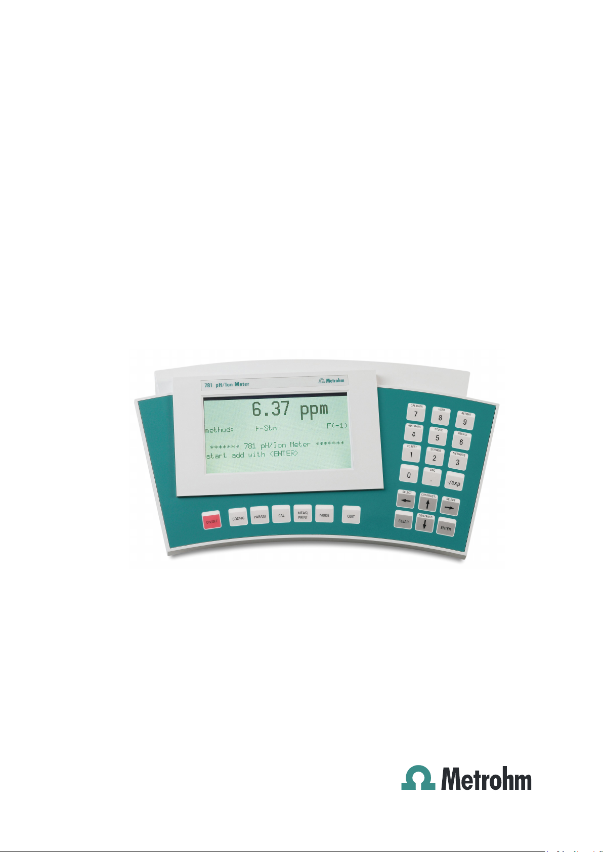
780 pH Meter / 781 pH/Ion Meter
Manual
8.781.8002EN / 2014-07-31
Page 2

Page 3

Metrohm AG
CH-9100 Herisau
Switzerland
Phone +41 71 353 85 85
Fax +41 71 353 89 01
info@metrohm.com
www.metrohm.com
780 pH Meter / 781 pH/Ion Meter
Program Version 5.780.0020 und 5.781.0020
8.781.8002EN / 2014-07-31
Manual
jb/ebe
Page 4

Teachware
Metrohm AG
CH-9100 Herisau
teachware@metrohm.com
This documentation is protected by copyright. All rights reserved.
Although all the information given in this documentation has been
checked with great care, errors cannot be entirely excluded. Should you
notice any mistakes please send us your comments using the address
given above.
Documentation in additional languages can be found on
http://documents.metrohm.com.
Page 5

Contents
780/781 pH/Ion Meter, Manual
Table of contents
1 Introduction .......................................................... 1
1.1 Instrument description ................................................................................. 1
1.2 Parts and controls ........................................................................................ 3
1.3 Information about this Manual ..................................................................... 5
1.3.1 Notation and pictograms ......................................................................... 5
1.4 Safety information ........................................................................................ 6
1.4.1 Electrical safety ........................................................................................ 6
1.4.2 General handling rules ............................................................................. 6
2 Installation ........................................................... 7
2.1 Instrument setup .......................................................................................... 7
2.1.1 Packaging ................................................................................................. 7
2.1.2 Checks ...................................................................................................... 7
2.1.3 Location .................................................................................................... 7
2.2 Connecting the accessories ........................................................................ 8
2.3 Connecting optional devices ....................................................................... 9
2.3.1 Connecting the 801 Magnetic Stirrer ....................................................... 9
2.3.2 Connecting the 802 Rod Stirrer ..............................................................10
2.3.3 Connecting a Dosimat Plus (only 781) ..................................................11
2.3.4 Connecting a sample changer ...............................................................12
2.3.5 Connecting a printer ...............................................................................13
2.3.6 Connecting a computer .........................................................................15
2.4 Connecting the electrodes and sensors ................................................... 16
2.5 Mains connection ....................................................................................... 17
2.6 Switch on .................................................................................................... 17
2.7 Initial configuration .................................................................................... 18
3 Short operating tutorial ..................................... 19
3.1 pH measurement ........................................................................................ 19
3.1.1 Requirements .........................................................................................19
3.1.2 Preparations ...........................................................................................19
3.1.3 pH calibration .........................................................................................20
3.1.4 pH measurement ....................................................................................22
3.2 Determination of an ion concentration (only 781: Conc mode) ............... 23
3.2.1 Requirements .........................................................................................23
3.2.2 Preparations ...........................................................................................23
3.2.3 Calibrating the fluoride ISE .....................................................................24
3.2.4 Direct measurement of fluoride ..............................................................28
4 Operation ........................................................... 31
4.1 The keypad ................................................................................................. 31
4.2 Operating concept ..................................................................................... 32
4.3 All key functions at a glance ...................................................................... 33
4.4 Operating principles .................................................................................. 38
4.4.1 Configuration and method parameters .................................................38
4.4.2 Editing menu entries ..............................................................................38
4.4.3 Entering text ............................................................................................39
I
Page 6

Contents
780/781 pH/Ion Meter, Manual
5 Configuration ..................................................... 41
5.1 Report ......................................................................................................... 42
5.2 Printing out measured values .................................................................... 44
5.3 Storing measured values ........................................................................... 47
5.4 Auxiliaries ................................................................................................... 48
5.5 Monitoring .................................................................................................. 51
5.6 Peripheral units .......................................................................................... 52
5.7 RS232 settings ........................................................................................... 54
6 Methods / Parameters ........................................ 55
6.1 Method management ................................................................................. 55
6.2 pH measurement (pH mode) ..................................................................... 56
6.2.1 Measuring parameters ........................................................................... 56
6.2.2 Calibration parameters........................................................................... 58
6.2.3 Limits pH ................................................................................................ 62
6.2.4 Limits T ................................................................................................... 62
6.2.5 Plot parameters ...................................................................................... 63
6.2.6 Preselections .......................................................................................... 63
6.2.7 Electrode test ......................................................................................... 64
6.3 Temperature measurement (T mode) ........................................................ 65
6.3.1 Measuring parameters ........................................................................... 65
6.3.2 Limits T ................................................................................................... 66
6.3.3 Plot parameters ...................................................................................... 67
6.3.4 Preselections .......................................................................................... 67
6.4 Potential measurement (U mode) .............................................................. 68
6.4.1 Measuring parameters ........................................................................... 68
6.4.2 Limits U................................................................................................... 69
6.4.3 Plot parameters ...................................................................................... 70
6.4.4 Preselections .......................................................................................... 70
6.5 Direct ion measurement (781 only: Conc mode) ...................................... 71
6.5.1 Type of measurement ............................................................................ 71
6.5.2 Ion parameters ....................................................................................... 71
6.5.3 Measuring parameters ........................................................................... 72
6.5.4 Calculation parameters .......................................................................... 74
6.5.5 Calibration parameters........................................................................... 75
6.5.6 Limits Conc ............................................................................................ 77
6.5.7 Limits T ................................................................................................... 78
6.5.8 Plot parameters ...................................................................................... 78
6.5.9 Preselections .......................................................................................... 79
6.6 Standard and sample addition (781 only: Conc mode) ............................ 80
6.6.1 Standard / Sample addition ................................................................... 80
6.6.2 Preselections .......................................................................................... 83
7 Various functions ............................................... 85
7.1 Calibration and addition/subtraction data ................................................ 85
7.1.1 pH calibration data ................................................................................. 85
7.1.2 Conc calibration data (781 pH/Ion Meter only) ..................................... 89
7.1.3 Addition/Subtraction data (781 pH/Ion Meter only) ............................... 93
7.2 Reports ....................................................................................................... 96
II
Page 7

Contents
780/781 pH/Ion Meter, Manual
7.2.1 Arrangement of a report .........................................................................98
7.2.2 Report identification ...............................................................................99
7.2.3 Measuring point report ...........................................................................99
7.2.4 Calibration report ..................................................................................101
7.2.5 Result report (781 pH/Ion Meter only) ..................................................102
7.2.6 Configuration report .............................................................................103
7.2.7 Parameter report ..................................................................................104
7.2.8 Measured values memory report .........................................................105
7.2.9 User method report ..............................................................................106
7.3 Measured values memory ........................................................................ 107
7.3.1 Save measured values .........................................................................107
7.3.2 Print measured values ..........................................................................107
7.3.3 Show measured values ........................................................................108
7.4 Limit monitoring ....................................................................................... 109
7.4.1 Uses ......................................................................................................109
7.4.2 How it functions ....................................................................................110
7.5 Setup ........................................................................................................ 111
7.5.1 Locking .................................................................................................111
7.5.2 Input assignment ..................................................................................112
7.5.3 Graphics ...............................................................................................112
8 Troubleshooting – Messages – Maintenance .. 113
8.1 Troubleshooting ....................................................................................... 113
8.2 Messages ................................................................................................. 115
8.3 QM support............................................................................................... 120
8.4 Validation .................................................................................................. 122
8.4.1 Electronic tests .....................................................................................122
8.4.2 Wet tests ...............................................................................................123
8.4.3 pH/Ion Meter maintenance...................................................................123
8.5 Diagnosis .................................................................................................. 124
8.6 pH electrode test ...................................................................................... 126
8.6.1 Preparations .........................................................................................126
8.6.2 Procedure .............................................................................................127
8.6.3 Results ..................................................................................................129
8.6.4 Messages and measures .....................................................................131
8.6.5 Care and maintenance of pH glass electrodes ...................................132
9 Annex ................................................................ 135
9.1 Technical data .......................................................................................... 135
9.1.1 Measuring modes ................................................................................135
9.1.2 Measuring inputs ..................................................................................135
9.1.3 Measuring input specifications ............................................................136
9.1.4 Interfaces ..............................................................................................136
9.1.5 Power supply ........................................................................................136
9.1.6 Safety specifications ............................................................................137
9.1.7 Electromagnetic compatibility (EMC) ..................................................137
9.1.8 Ambient temperature ............................................................................137
9.1.9 Reference conditions ...........................................................................137
9.1.10 Dimensions ...........................................................................................137
9.2 Evaluation ................................................................................................. 138
III
Page 8

Contents
780/781 pH/Ion Meter, Manual
9.2.1 pH calibration ....................................................................................... 138
9.2.2 Calibration for ion measurements ........................................................ 142
9.2.3 Addition method ................................................................................... 143
9.3 Menu structures ....................................................................................... 144
9.3.1 Instrument configuration ...................................................................... 144
9.3.2 Method parameters in the pH mode ................................................... 146
9.3.3 Method parameters in the T mode ...................................................... 147
9.3.4 Method parameters in the U mode...................................................... 147
9.3.5 Method parameter in the Conc mode ................................................. 148
9.4 Stored buffer series ................................................................................. 150
9.5 Remote box .............................................................................................. 156
9.5.1 Pin occupancy of the remote connection of the Remote box ............. 156
9.5.2 Functions of the individual remote lines .............................................. 157
9.6 Accessories .............................................................................................. 158
9.7 Warranty (guarantee) ............................................................................... 160
10 Index ................................................................. 163
IV
Page 9

Contents
780/781 pH/Ion Meter, Manual
List of illustrations
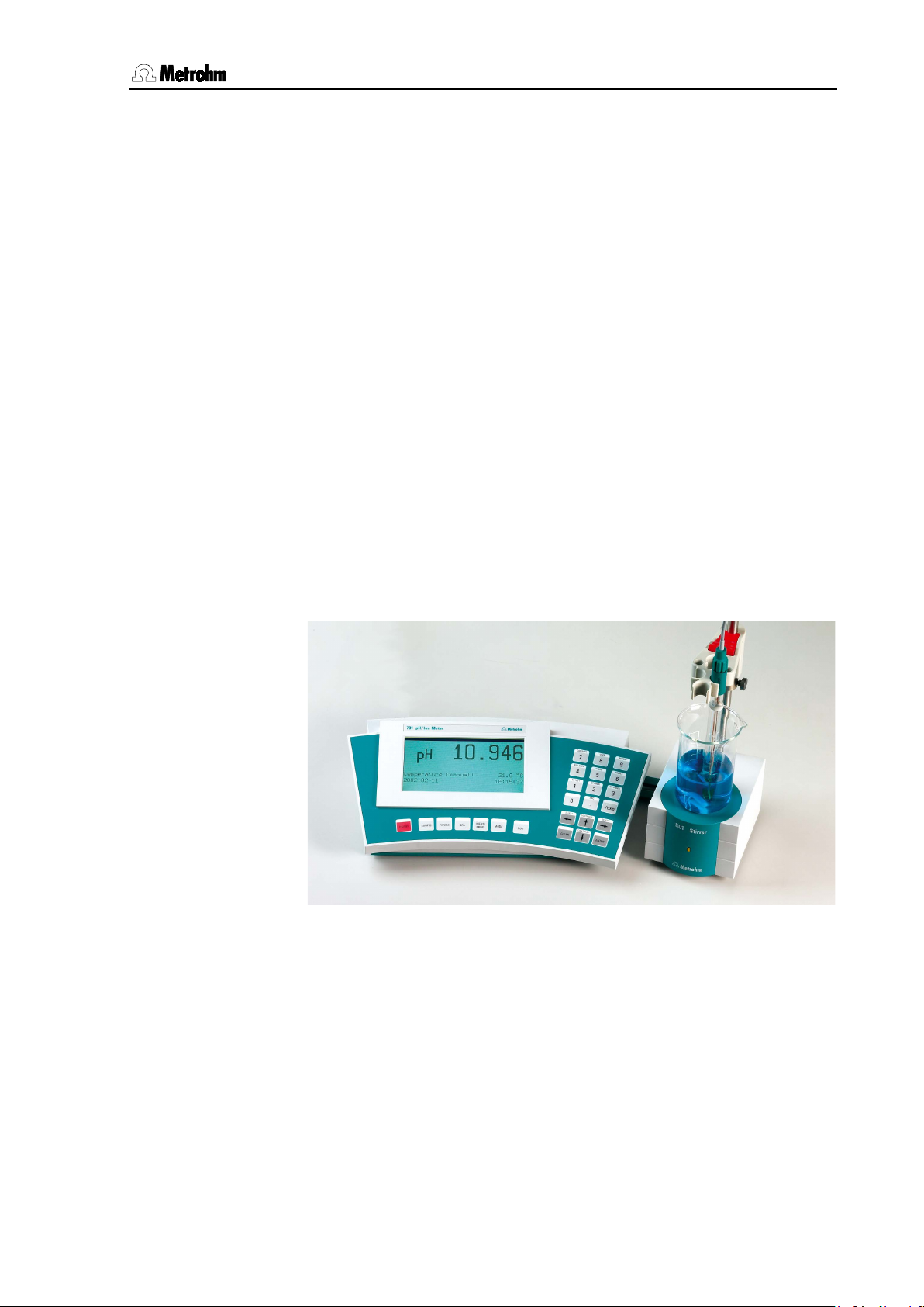
Fig. 1: 781 pH/Ion Meter connected to 801Magnetic Stirrer .................................................... 1
Fig. 2: Front view of the 780 pH Meter or 781 pH/Ion Meter .................................................... 3
Fig. 3: Rear view of the 780 pH Meter or 781 pH/Ion Meter ..................................................... 4
Fig. 4: Possible arrangements for mounting the base plate .................................................... 8
Fig. 5: Attaching the support rod and base plate..................................................................... 8
Fig. 6: Ready-mounted pH/ISE measuring system .................................................................. 9
Fig. 7: 780 pH Meter / 781 pH/Ion Meter – 801 Magnetic stirrer .............................................. 9
Fig. 8: 780 pH Meter / 781 pH/Ion Meter – 802 Rod stirrer .................................................... 10
Fig. 9: 781 pH/Ion Meter – Dosimat Plus ................................................................................ 11
Fig. 10: 781 pH/Ion Meter – Dosimat Plus – Sample changer ............................................... 12
Fig. 11: 780 pH Meter / 781 pH/Ion Meter – Printer ............................................................... 13
Fig. 12: Connecting sensors ................................................................................................... 16
Fig. 13: Remote outputs in limit monitoring .......................................................................... 110
Fig. 14: Diagram showing changes in potential during an electrode test ........................... 129
Fig. 15: Theoretical U/pH relationship ................................................................................ 138
Fig. 16: 3-Point pH calibration .............................................................................................. 139
Fig. 17: Connections of the optional 6.2148.010 Remote box ............................................. 156
Fig. 18: Pin occupancy at remote interface .......................................................................... 156
V
Page 10

Page 11
1 Introduction
780/781 pH/Ion Meter, Manual
780 pH Meter
781
pH/Ion Meter
Electrodes in Potentiometry
Application Notes
Application
Bulletins
781 pH/Ion Meter
780 pH Meter,
781 pH/Ion Meter
780 pH Meter
Conc
mode
1 Introduction
This Manual provides you with a comprehensive overview of the installation, working principles and operation of the
measuring modes of the 780 pH Meter are concerned (pH, temperature
and potential) and their operation in these modes is also identical, the
Manuals for both have been incorporated in a single document. The
special measuring mode of the 781 pH/Ion Meter – the measurement of
concentration – is, like the other measuring modes, described in separate sections. These sections, which apply only to the operation of the
781 pH/Ion Meter, are marked accordingly.
Information about the use of Metrohm pH or ion-selective electrodes
can be found in the appropriate leaflet and the ISE Manual that is included with the electrode.
Additional theoretical principles can be found in the Metrohm Monograph "
. As these two instruments are identical as far as the three
".
and
You can also request our descriptions of applications involving pH and
ISE measurements in the form of
Internet under
from your local Metrohm agency or download them from the
www.metrohm.com.
Fig. 1: 781 pH/Ion Meter connected to 801Magnetic Stirrer
1.1 Instrument description
and
Both instrument versions, the
are used for measuring pH, temperature and potential reliably and at
high resolution. The
having an additional operating mode for the potentiometric determination of the concentration by using ion-selective electrodes (
).
Both instruments have comprehensive monitoring functions (for calibration, validation and service intervals), diagnostic functions and an au-
differs from the
and the
by
1
Page 12

1.1 Instrument description
780/781 pH/Ion Meter, Manual
781 pH/Ion Meter
Conc mode
calibration
standard addition
tomatic pH electrode test. Up to 100 values can be stored in the
memory together with the most important additional data; these can be
viewed and outputted as a report. All the parameter settings for a
measuring mode can be permanently stored as a method.
All stored information (measured values, configuration, parameters,
etc.) can be transmitted via the RS 232 interface to a printer or computer for output as a report.
Both instruments have the following features:
• Dot-matrix display for both the continuous display of the measured
value and for showing the user dialog.
• High-impedance measuring input for pH, redox or ISE sensors, a
connection for a separate reference electrode and an input for temperature sensors (Pt1000 or NTC).
• MSB connection (Metrohm Serial Bus) for a stirrer and for a
Dosimat Plus.
• RS 232 connection for a serial printer or a computer.
• A connection for an external keyboard or a barcode reader.
The
has an additional
which allows the
measurement of the concentration by using ion-selective electrodes, either directly after calibration or by standard or sample addition methods. Such a
or
can be carried out either
manually or automatically. In the latter method a standard solution is
added automatically by a Dosimat Plus included in the system. The calibration concentrations or the standard additions are calculated automatically according to the given conditions and these are added with
great accuracy.
2
Page 13
1 Introduction
780/781 pH/Ion Meter, Manual
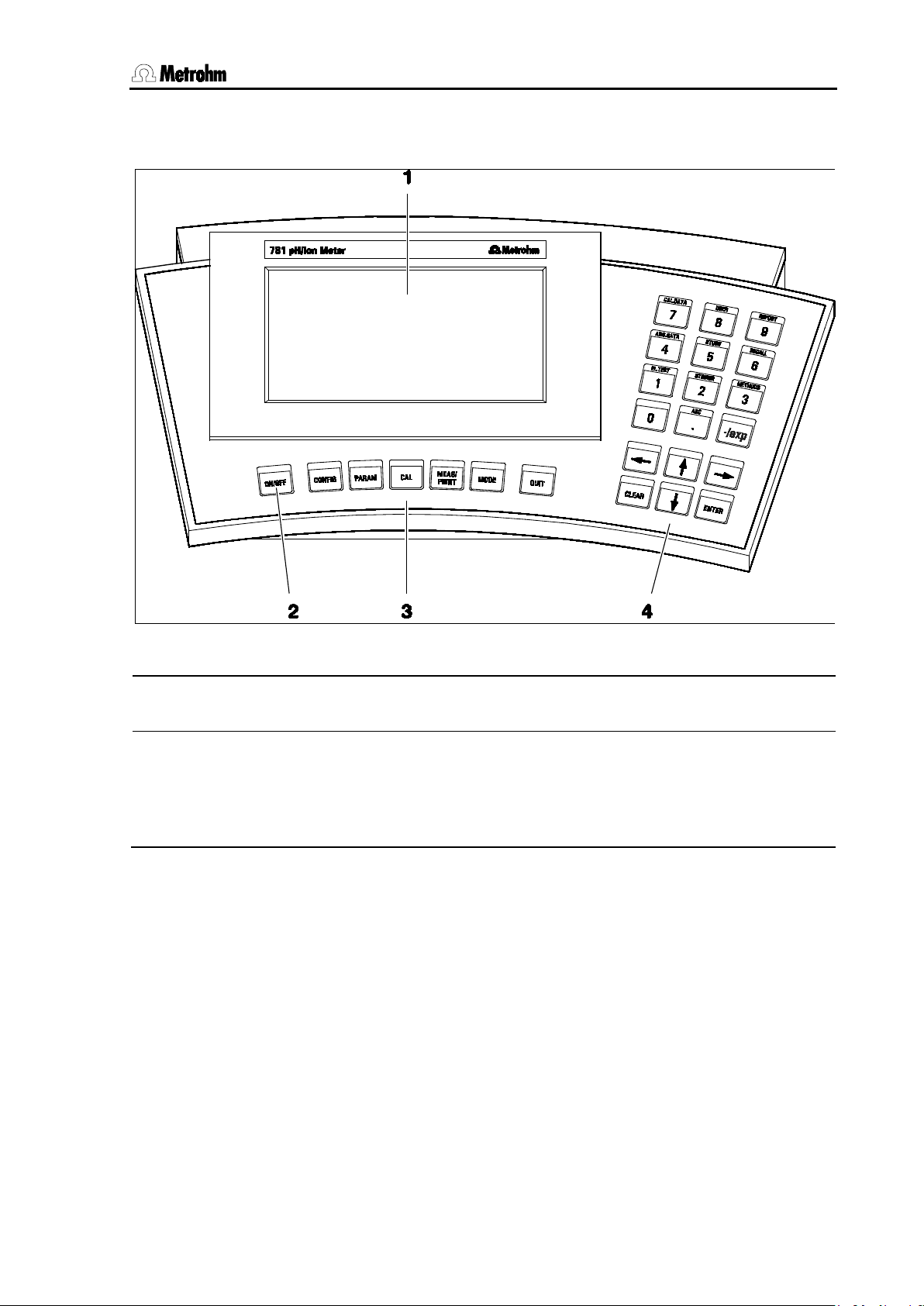
1 LCD display
3 Main function keys
2 On/Off key
4 Input, navigation and
function keys
1.2 Parts and controls
Fig. 2: Front view of the 780 pH Meter or 781 pH/Ion Meter
Key for switching the instrument on and
off
Each key has several functions;
the particular function depends on the
work status of the instrument
3
Page 14
1.2 Parts and controls
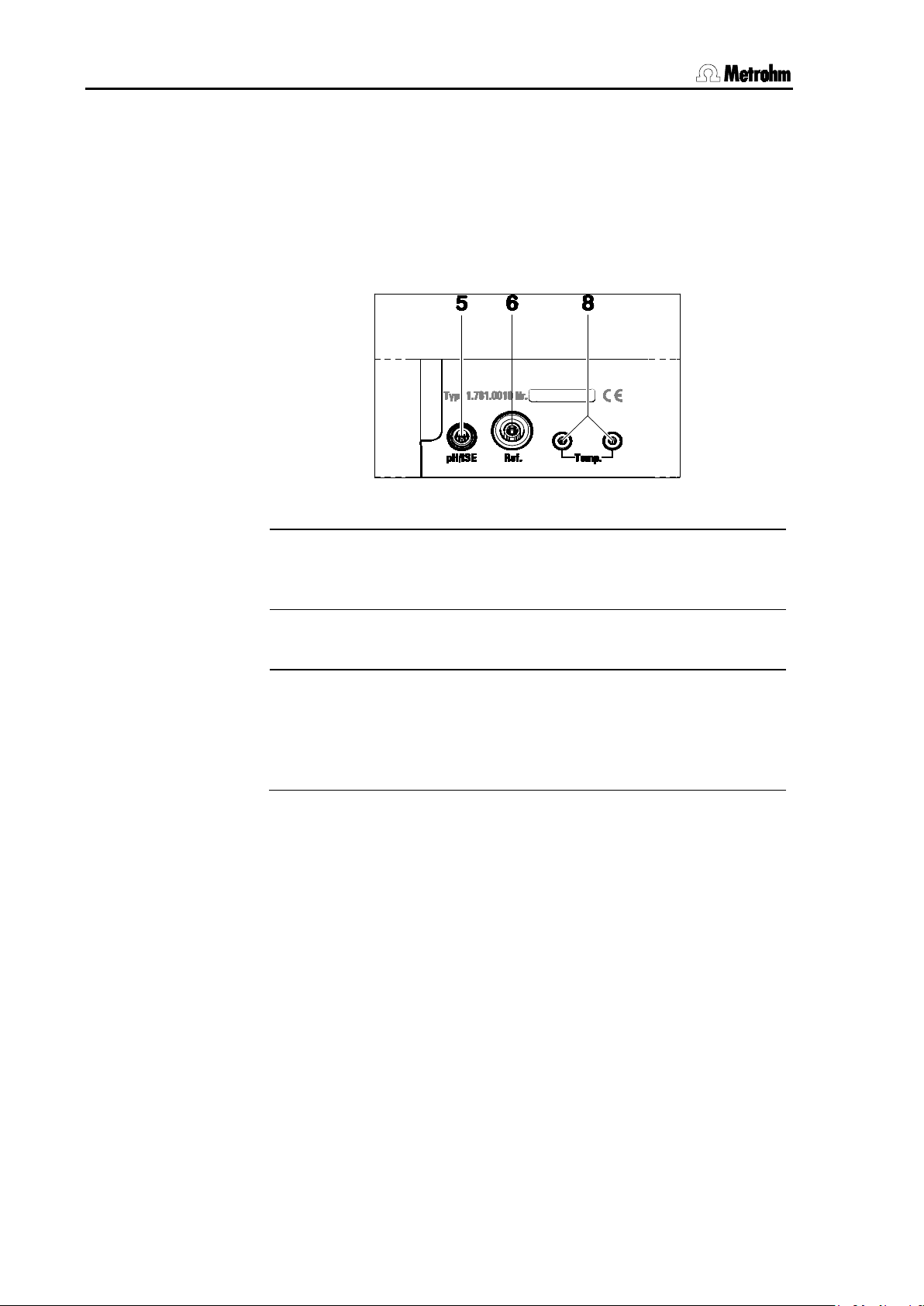
780/781 pH/Ion Meter, Manual
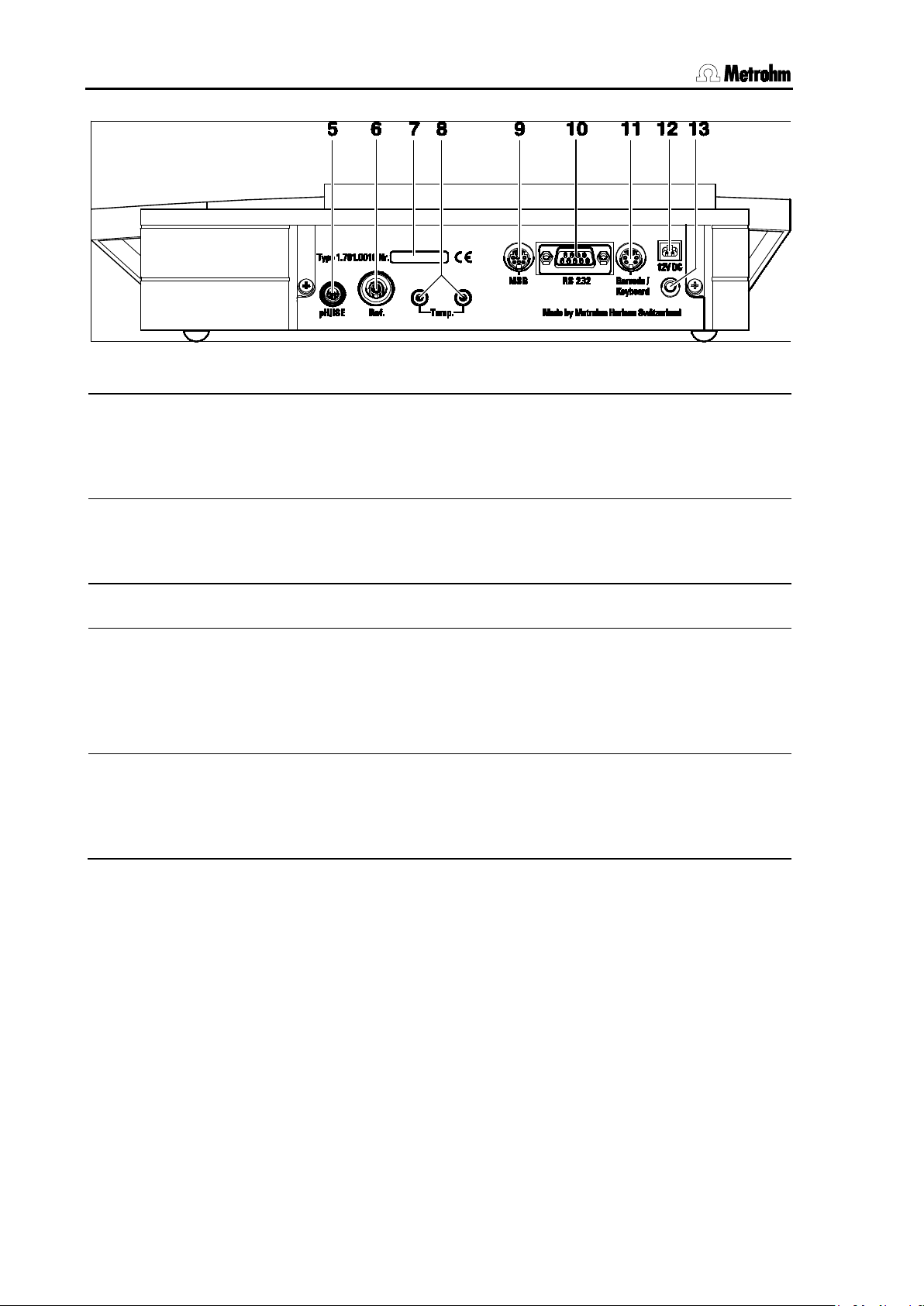
5 Connection for potentiometric electrodes
10
RS232 interface
6 Connection for separate reference
electrode
11
Barcode reader/
Keyboard connection
7 Serial number
12
12V power connection
8 Connection for temperature sensor
13
Grounding connection
9
MSB connection
, directly or via
Fig. 3: Rear view of the 780 pH Meter or 781 pH/Ion Meter
pH, ISE, redox or silver electrodes
Connection for printer or PC
with built-in or separate reference electrode; socket type F
4 mm socket type B
Pt1000 or NTC, for connection with two 2
mm B-plugs; 6.2103.130 and 6.2103.140
Adapters are included for use with 4 mm
banana plugs
(Metrohm Serial Bus) for connecting a
stirrer and/or Dosimat Plus
the optional Remote Box (6.2148.010)
For measurements in grounded solu-
tions, grounding of the instrument
may be advantageous to avoid inter-
ferences; 4 mm socket type B
4
Page 15
1 Introduction
780/781 pH/Ion Meter, Manual
Menu item, parameter or input value
<MODE>
Key
12
Operating element
Danger
Warning
Attention
Information
TIP !
TIP
1.3 Information about this Manual
Please study this Manual carefully before you start to use the instrument. The Manual contains information and warnings that must be observed by the user in order to guarantee the safe use of the instrument.
1.3.1 Notation and pictograms
The following notations and pictograms (symbols) are used in this
Manual:
Range
This symbol indicates a possible risk of death
or injury if the given information is not properly
observed.
This symbol indicates a possible risk of damage to the instrument or its components if the
given information is not properly observed.
This symbol indicates important information.
Please read it carefully before you continue.
This symbol indicates additional information
and tips.
This symbol indicates information that may be
of particular use to you.
5
Page 16
1.4 Safety information
780/781 pH/Ion Meter, Manual
Warning!
ng with water or other solutions in the immediate vicinity of
1.4 Safety information
This instrument should only be used in accordance with the information given in this Manual.
1.4.1 Electrical safety
Please observe the following guidelines:
• Only qualified Metrohm technicians should carry out service work
on electronic components.
• Do not open the pH/Ion Meter housing. This could destroy the
pH/Ion Meter. Inside the housing there are no components that the
user can service or exchange.
Electrical safety when handling the 780 pH Meter and the 781 pH/Ion
Meter is guaranteed within the framework of the IEC 61010 Standard.
The following points must be observed:
Please make sure that the external power supply is always kept dry.
Protect it against direct liquid contact .
Electronic components are sensitive to electrostatic charges and can
be destroyed by a discharge. Always switch off the pH/Ion Meter before making or breaking electrical connections on the rear panel of the
instrument.
1.4.2 General handling rules
Handling solutions
When worki
the pH/Ion Meter please avoid excessive liquid splashes on the instrument housing or power supply. Any such splashes must be removed as quickly as possible in order to prevent the liquid from entering the instrument or the power supply.
6
Page 17

2 Installation
780/781 pH/Ion Meter, Manual
2 Installation
2.1 Instrument setup
2.1.1 Packaging
The 780/781 pH/Ion Meter and its specially packed accessories are
supplied in very protective special packaging made of shock absorbing
polypropylene foam. Please store this packaging in a safe place; it is
the only way in which the safe transport of the instrument can be guaranteed. Should you wish to dispose of it please consider suitable disposal or recycling processes.
2.1.2 Checks
Please check that the delivery is complete and undamaged immediately on receipt (compare with delivery note and list of accessories given in
Section 9.6).
2.1.3 Location
Place the instrument on a suitable vibration-free laboratory bench, protected from corrosive atmospheres and contact with chemicals.
7
Page 18

2.2 Connecting the accessories
780/781 pH/Ion Meter, Manual
stand base
C
2.2 Connecting the accessories
Both the stand for attaching the stirrer, clamping ring and electrode
holder as well as the pH/Ion Meter itself can be mounted on the supplied
You can chose between the arrangements shown in Fig. 4 to suit your
own particular working preference.
.
Fig. 4: Possible arrangements for mounting the base plate
Versions A and B are intended for mounting an 801 Magnetic stirrer on
the left- and right-hand side of the pH/Ion Meter respectively. If you frequently work without such a permanently attached stirrer then you can
mount the base plate so that you have space for the sample vessel directly in front of the support rod (versions
Attach the base plate with the screws provided as shown in Fig. 5. The
rubber feet included prevent the system from slipping about on the
work bench and should therefore be stuck on to the base plate.
and D).
Fig. 5: Attaching the support rod and base plate
8
Page 19
2 Installation
780/781 pH/Ion Meter, Manual
9
801 Magnetic Stirrer
802 Rod Stirrer
804 Ti-Stand
Dosimat Plus
801 Magnetic Stirrer
2.3 Connecting optional devices
Devices which are to be remotely controlled from the pH/Ion Meter (e.g.
Metrohm stirrers or Dosimat Plus devices) are connected to MSB connection
6.2148.010 Remote Box (e.g.
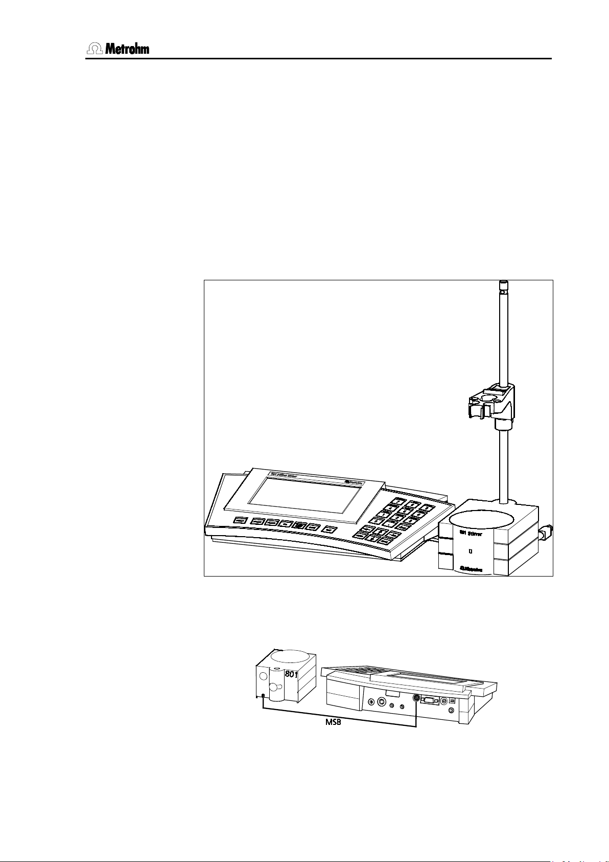
2.3.1 Connecting the 801 Magnetic Stirrer
Mount the magnetic stirrer on the support rod before attaching the
clamping ring (6.2013.010) and the electrode holder (6.2021.020). Further details are given in the corresponding Manual.
For example, the ready-mounted system could look like this:
. This can be carried out either directly (
with
) or via the optionally available
).
or
Fig. 6: Ready-mounted pH/ISE measuring system
The
is connected to it directly:
Fig. 7: 780 pH Meter / 781 pH/Ion Meter – 801 Magnetic stirrer
is controlled via MSB connection 9. The stirrer
9
Page 20
2.3 Connecting optional devices
780/781 pH/Ion Meter, Manual
802 Rod Stirrer
804 Ti Stand,
9
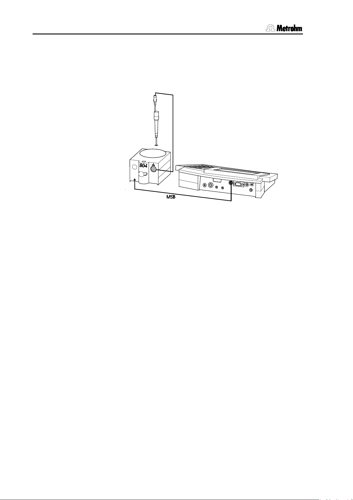
2.3.2 Connecting the 802 Rod Stirrer
The
connected directly to the pH/Ion Meter. This is done by plugging the
MSB connection cable of the 804 Ti Stand into MSB connection
pH/Ion Meter:
Fig. 8: 780 pH Meter / 781 pH/Ion Meter – 802 Rod stirrer
, in combination with the
can also be
of the
10
Page 21
2 Installation
780/781 pH/Ion Meter, Manual
Controlled addition of standard or sample solutions
781 pH/Ion Meter
865
876
DOS
Furthermore, the Dosimat Plus
“HOLD”
“HOLD”
“HOLD”
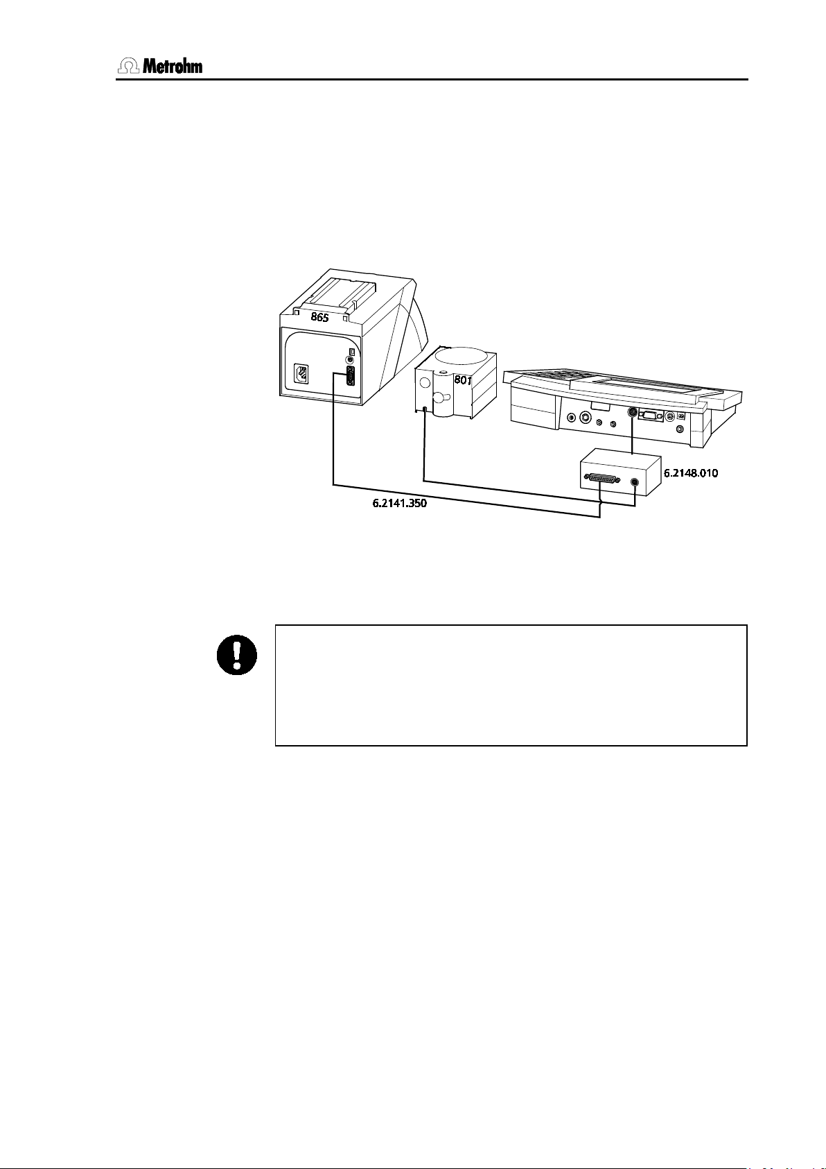
2.3.3 Connecting a Dosimat Plus (only 781)
For automatic calibration as well as for the addition of standard or
samples in the Conc mode with the
and
available 6.2148.010 Remote Box. Control is carried out via the
6.2141.350 cable:
Dosimat Plus devices can be connected via the separately
the Metrohm
Fig. 9: 781 pH/Ion Meter – Dosimat Plus
If a Dosimat Plus is used then a stirrer is normally also required. This is
then connected directly with the MSB connection of the 6.2148.010
Remote Box (stirrer: 801 or 802+804).
Please note that for the standard addition the mode “
the Dosimat Plus. The activation pulse must be activated on the pH
Meter as well as the Dosimat Plus.
must be in the status
pressing the “Go” key once (check: the display of the Dosimat Plus
shows
in the top right-hand corner).
. You can set the status to
” is set on
by
11
Page 22
2.3 Connecting optional devices
780/781 pH/Ion Meter, Manual
Compact Sample Changer 869
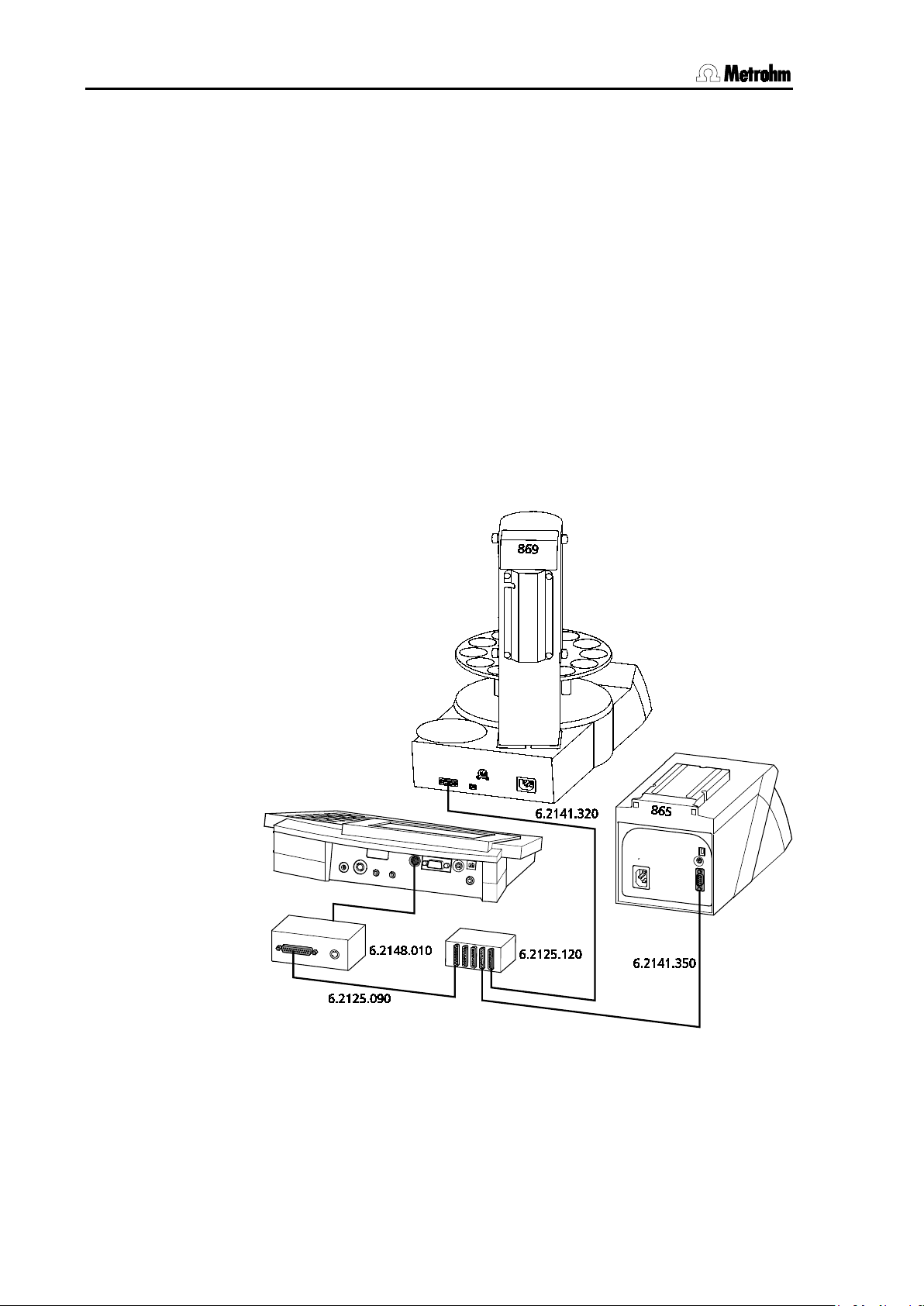
2.3.4 Connecting a sample changer
For simple automated measurement of several samples and standards
with the pH/Ion Meter the Metrohm
be connected. Communication takes place via the 6.2148.010 Remote
Box, i.e. the measurements are triggered by the sample changer and
their completion is also transmitted by the pH/Ion Meter via the remote
connection. The individual steps for processing a series of samples or
standards are defined as a method in the sample changer.
Please note that when work is carried out in this way that no sample data is transferred between the sample changer and the pH/Ion Meter.
This means that the assignment of the report outputs is only possible
by using the consecutive run number (see Section 5.4).
The connection of a Compact Sample Changer 869 and a Dosimat Plus
865 for automatic calibration with standard addition is described here
as an example. A detailed description of how to program a method in
the Compact Sample Changer 869 is given in the corresponding Manual of the instrument.
can
Fig. 10: 781 pH/Ion Meter – Dosimat Plus – Sample changer
12
Page 23
2 Installation
780/781 pH/Ion Meter, Manual
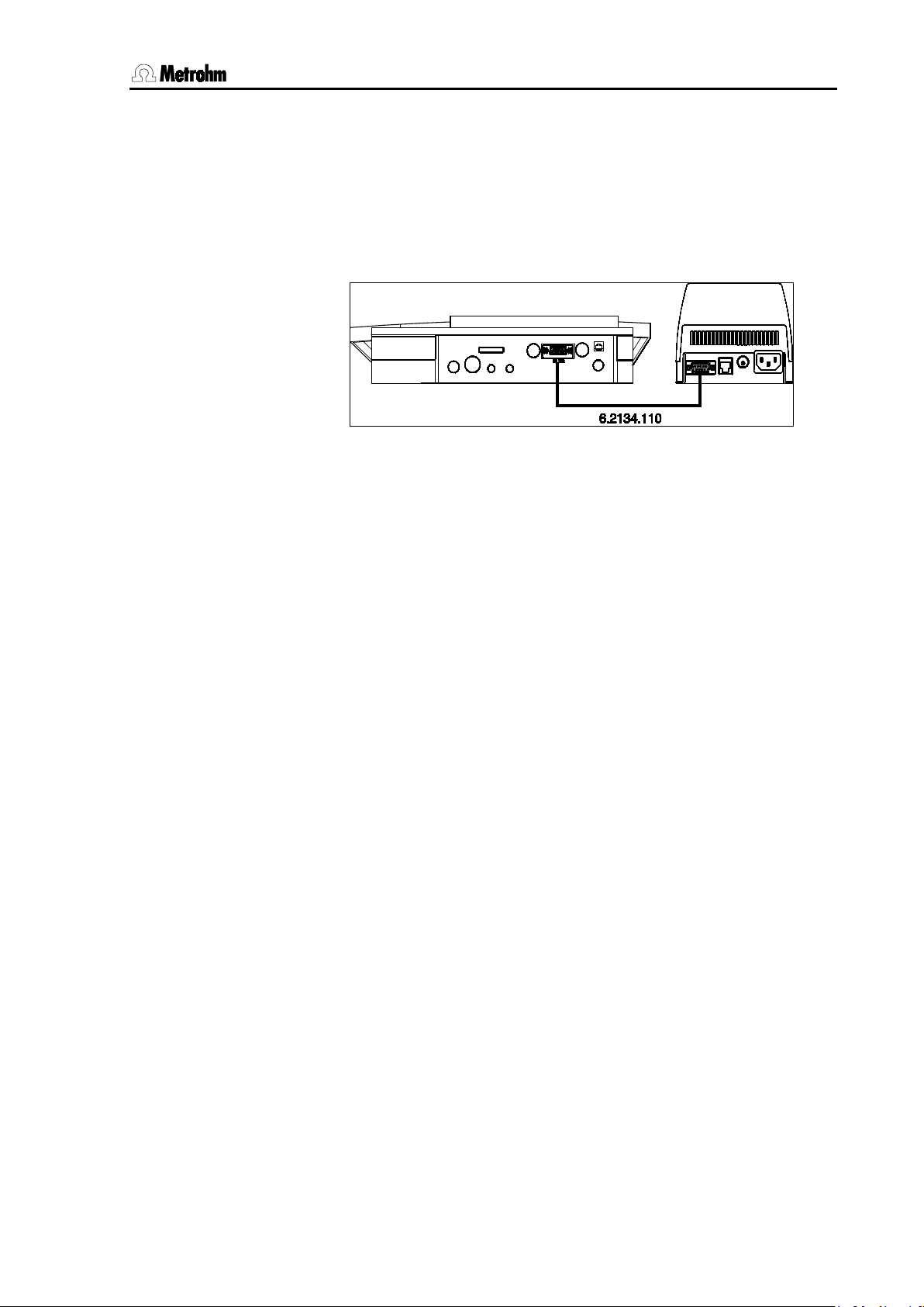
2.3.5 Connecting a printer
A printer with a serial or parallel interface can be connected to the
RS232 interface for printing out reports.
The connection of the 40-character Custom DP40-S4N printer
(Metrohm ordering number: 2.140.0200) with the serial 6.2134.110 Cable is described as an example:
Fig. 11: 780 pH Meter / 781 pH/Ion Meter – Printer
The transmission parameters for the pH/Ion Meter and the printer must
be the same. On the pH/Ion Meter these are set under
CONFIG/peripheral units/character set: (see Section 5.6)
and under
CONFIG/RS232 settings (see Section 5.7).
These settings and other possible printer connections are given in the
following table. If you wish to connect a printer which is not mentioned
here then make sure that it emulates the Epson mode or uses the international character set according to IBM Standard Table 437 and IBMcompatible graphics control characters.
Please observe the paper feed settings after each report printout (see
Section 5.1).
The settings for graph sizes in the printer output are accessible in the
setup of the pH/Ion Meter and are described in Section 7.5.3. This can
particularly be necessary for single sheet printers (i.e. HP Desk Jet).
13
Page 24
2.3 Connecting optional devices
780/781 pH/Ion Meter, Manual
IDP-560 EMULATION
GERMANY also for Swedish.
Seiko
6.2134.110
Character Set: Seiko
Handshake: HWs
none
Handshake: HWs
Character Set: Epson
Handshake: HWs
HP Desk Jet
2.145.0330
Character Set: HP
see Printer Manual
ON
1 2 3 4 5 6 7 8 9
10
SSW1
2
1 2 3 4 5 6 7
8
B:
A4 Paper
A:
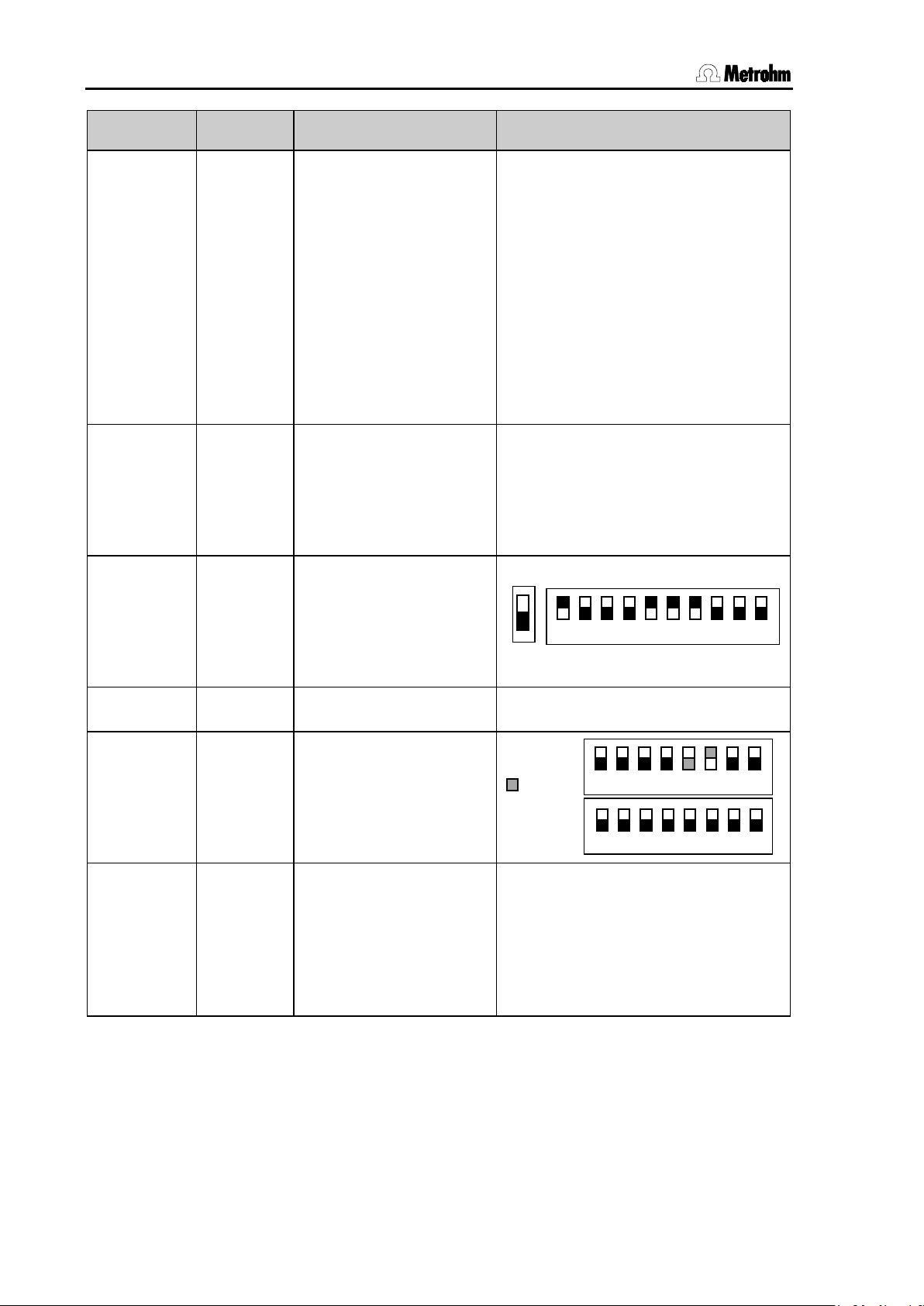
Printer Cable 780/781 settings Printer settings
Custom
DP40-S4N
DPU-414
Citizen
iDP562 RS
6.2134.110 Character Set: Citizen
Baud Rate: 9600
Data Bit: 8
Stop Bit: 1
Parity: none
Handshake: HWs
Baud Rate: 9600
Data Bit: 8
Stop Bit: 1
Parity: none
6.2134.050 Character Set: Citizen
Baud Rate: 9600
Data Bit: 8
Stop Bit: 1
Parity: none
FONT MAP = ENGLAND *
PRINT = REVERSE
LITTLE
CR CODE = VOID
CR AFTER B. FULL = VOID
CR ON B. EMPTY = VALID
BUFFER 1K BYTE
BAUD RATE = 9600
PROTOCOL = 8,N,1
FLOW CONTROL CTS-RTS
(*) FRANCE also for Italian, Spanish
and Portuguese,
Epson LX300+
HP Desk Jet
with serial
interface
with parallel
interface
6.2134.050 As above, but
6.2134.050 Character Set: HP
Baud Rate: 9600
Data Bit: 8
Stop Bit: 1
Parity: none
RS232/
Parallel
Converter
Baud Rate: 9600
Data Bit: 8
Stop Bit: 1
Parity: none
Handshake: HWs
see Printer Manual
14
Page 25
2 Installation
780/781 pH/Ion Meter, Manual
Settings
switched on. When the Vesuv program is started it automatically
checks the configuration of the connected instrument and makes the
corresponding settings for the report output so that data acquisition
2.3.6 Connecting a computer
The report output via the RS232 interface can be made to either a printer or a PC. With the program Metrodata Vesuv 3.0 for Windows it is
possible to implement automatic data acquisition and evaluation.
This is done by connecting RS232 interface 10 of the pH/Ion Meter using the optionally available 6.2134.040 Cable (9-pin/9-pin) with a free
serial COM port on the PC. If only a 25-pin COM port is available then
the optionally available 6.2125.110 Cable (9-pin/25-pin) or a commercially available adapter must be used.
The RS232 interface must be configured with identical settings on both
the connected instruments (PC and pH/Ion Meter). You should select
the standard values for the pH/Ion Meter configuration under
FIG/RS232 settings
Baud Rate: 9600
Data Bit: 8
Stop Bit: 1
Parity: none
Handshake: HWs
Please note that, before starting the program 'Vesuv Datalogger', the
pH/Ion Meter must have been configured correctly, connected up and
CON-
(see Section 5.7):
functions properly.
As well as the data acquisition function described above, the 780/781
pH/Ion Meter also has numerous remote control possibilities that allow
the complete control of the instrument via the RS232 interface. However, as the utilization of this option only makes sense in very special situations, you can obtain detailed information about the remote control
language of the pH/Ion Meter from your local Metrohm agency in a
separate document (780/781 pH/Ion Meter Operation via RS232;
8.781.1113).
15
Page 26
2.4 Connecting the electrodes and sensors
780/781 pH/Ion Meter, Manual
5
8
switched off
5
Connection for potentiometric electrodes
6
Connection for separate reference electrode
8
Connection for temperature sensor
2.4 Connecting the electrodes and sensors
On its rear panel the 780/781 pH/Ion Meter has connections for a potentiometric electrode
perature sensor
Connect your electrodes and sensors according to the following diagram to the
.
, a separate reference electrode 6 and a tem-
pH/Ion Meter:
Fig. 12: Connecting sensors
pH, ISE, redox or silver electrodes with built-in or separate
reference electrode; plug F
plug B, 4 mm
Pt1000 or NTC, connected via two 2 mm banana plugs, reducing adapters for 4 mm plug B may be necessary
(6.2103.130 / 6.2103.140). Please observe color classification
for shielding purposes.
To help you choose the optimal potentiometric electrode for your particular application Metrohm can provide you with a range of information
material:
Catalog: Metrosensor Electrodes
Product booklet: Electrodes for pH Measurement
Monograph 8.015.5003: Electrodes in Potentiometry
You can obtain these documents from your local Metrohm agency or
under www.metrohm.com.
16
Page 27
2 Installation
780/781 pH/Ion Meter, Manual
12
Mains cable
e sure that the power supply is always kept dry. Protect it
<ON/OFF>
2.5 Mains connection
The pH/Ion Meter has an external power supply (6.2153.000) providing
12V (DC). This is connected to 12V mains connection
One of the following cables is supplied with the instrument
• 6.2154.000 Mains cable 2 Pol (C7) – EU (XVI)
• 6.2154.010 Mains cable 2 Pol (C7) – US (N1/15)
• 6.2154.020 Mains cable 2 Pol (C7) – GB (BS89/3)
• 6.2154.030 Mains cable 2 Pol (C7) – AUS (SAA/2)
and is connected to the external power supply.
Please mak
against direct liquid contact .
2.6 Switch on
.
ON/ OFF
After the selected accessories have been connected switch on the
pH/Ion Meter with the
strument will start in the last operating mode to have been used for
measuring pH, temperature, potential or concentration (781 only).
During the switch-on process an instrument checking routine is carried
out automatically. If an error message is displayed here ('
please contact your local Metrohm agency.
key (see also Section 4.3). The in-
Err x') then
17
Page 28

2.7 Initial configuration
780/781 pH/Ion Meter, Manual
<CLEAR>
Dialog language: english
<ENTER>
Date and time
Temperature sensor and unit
2.7 Initial configuration
The pH/Ion Meter is delivered with standard settings for the configuration and method parameters. Many of these can be reset at any time by
pressing the
should ever be necessary to reset the configuration of the instrument to
its original condition then this can be carried out by a re-initialization of
the instrument memory (see Section 8.5).
Before you start to make measurements please check the following
configuration settings and, if necessary, alter them according to your
own requirements. If you first want to make yourself familiar with the
operation of the pH/Ion Meter and the various editing possibilities then
please read Sections 4.1, 4.2 and 4.4. More detailed explanations of the
individual configuration settings are given in Section 5.
CONFIG/Verschiedenes/Dialog:english
key during input (see also Section 4.3). If it
After this choice has been confirmed with
guage changes immediately. For example, this item would then appear.
CONFIG/auxiliaries/dialog:english
Please switch the instrument off and on if this setting has been
changed.
CONFIG/auxiliaries/date
and /time
Please check that the date and time are correct.
CONFIG/auxiliaries/Temp.sensor
and /Temp.unit
Enter the type of temperature sensor that is connected. If no temperature sensor is connected and you always want to enter the measuring
temperature manually then you can ignore this setting.
the dialog lan-
18
Page 29

3 Short operating tutorial
780/781 pH/Ion Meter, Manual
780 pH Meter (2.780.0010)
781 pH/Ion Meter (2.781.0010)
801 Magnetic Stirrer (2.801.0010)
pH electrode (enclosed)
Calibration buffers
3 Short operating tutorial
In this section the necessary steps for carrying out a simple pH and ion
measurement with calibration are described. The instructions are limited to those steps that are absolutely necessary and will enable you to
carry out your first measurements with the pH/Ion Meter directly. The
operating principles are described in Section 4.4.
3.1 pH measurement
3.1.1 Requirements
The following instruments, accessories and solutions are required for
carrying out the pH calibration and measurement described below:
•
•
Other stirrers can also be used (see Section 5.6).
•
Or another pH electrode with Pt1000 temperature sensor, e.g.:
6.0258.600 Unitrode, LL pH glass, with cable 6.2104.600, 2 mm
temp. plug
6.0257.000 Aquatrode Plus for ion-deficient water, 4 mm temp. plug
6.0228.000 Solitrode, LL pH glass, PP shaft, 4 mm temp. plug
or
•
Metrohm buffer solutions pH 4.00, 7.00 and 9.00 (6.2307.230)
3.1.2 Preparations
Before you start this short tutorial you must ensure that the instrument
and accessories have been correctly installed as described in Sec-
tion 2. The most important points concerning the installation are briefly
given again below (please refer to the Section mentioned for details). If
you are not certain whether all the settings (
pH
) correspond to the original conditions you can first reset any altera-
tions by initializing the memory (
tion 8.5).
The calibration parameters for the pH mode are set for a calibration using two Metrohm buffers as default (see Section 6.2.2). If you want to
use other buffers then the corresponding buffer type must be entered.
1 pH/Ion Meter installation
CONFIG and PARAMETER
RAM Initialization) (see Sec-
• Set up instrument Section 2.1
• Connect stirrer Section 2.3.1
• Connect electrode Section 2.4
• Mains connection Section 2.5
19
Page 30
3.1 pH measurement
780/781 pH/Ion Meter, Manual
pH 7
<STIRRER>
<CAL>
ENTER>
pH 4
<ENTER>
the measurement display. This can also be done immediately
<ENTER>
ON/ OFF
2 Initial configuration
CONFI G
3.1.3 pH calibration
1 Start calibration with first buffer
CAL
2 Continue calibration with second buffer
ENT ER
• Switch on pH/Ion Meter Section 5.4
• Set dialog language Section 5.4
• Set date/time Section 5.4
• Set temperature sensor Section 5.4
• Immerse pH electrode in buffer solution
• Switch on stirrer with
• Start calibration with
• If no temperature sensor is connected:
enter the temperature and exit with
<
• Remove pH electrode from first buffer, rinse with water and
blot off gently with a lint-free tissue
• Immerse pH electrode in second buffer solution
continue calibration sequence with
and
ENT ER
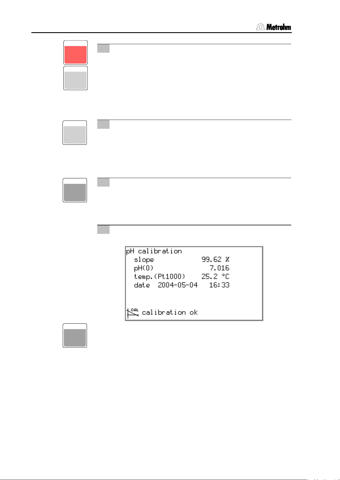
3 Result
• Wait for potential measurement, result will be displayed:
• After 30 s the pH/Ion Meter will switch back automatically to
with
.
20
Page 31

3 Short operating tutorial
780/781 pH/Ion Meter, Manual
<ENTER>,
<MODE>
<CAL.DATA>
< -> >
<->>
<REPORT>
<CAL.DATA>
b short); this contains
<->>
ENT ER
CAL. DA T A
REPORT
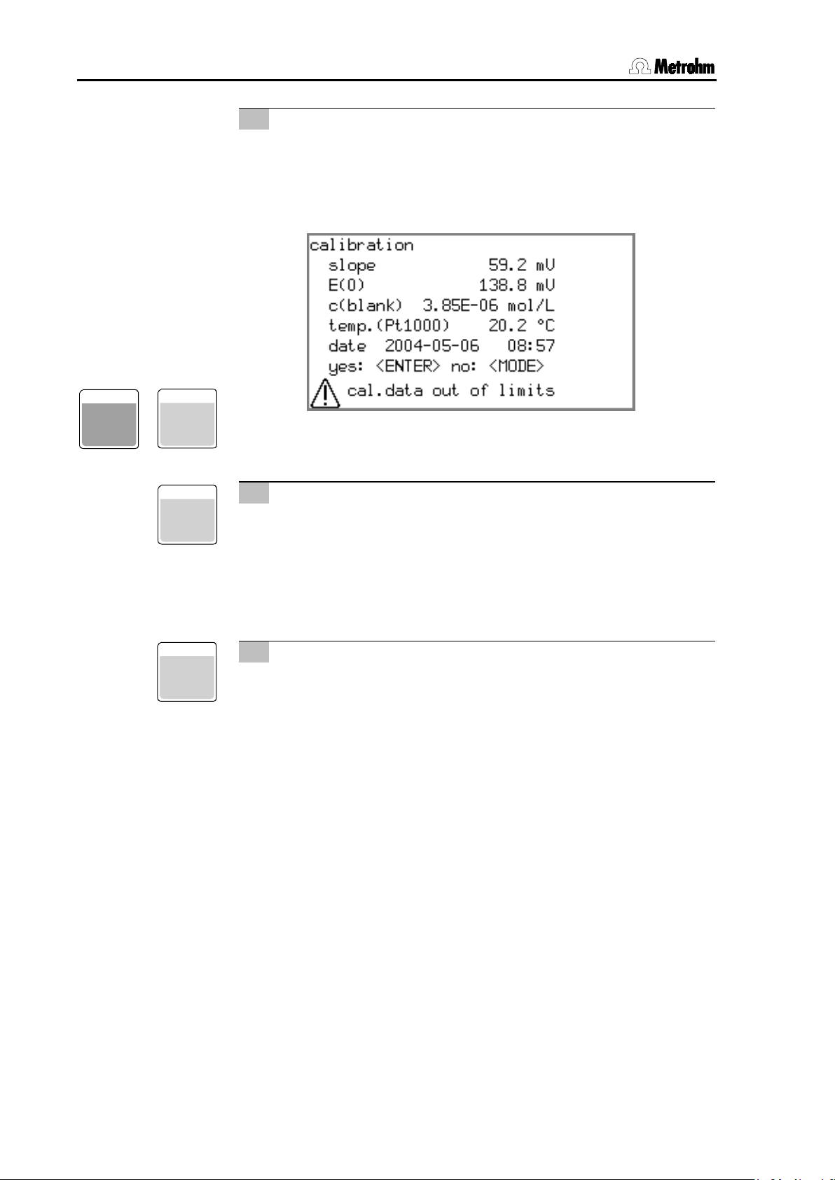
4 Poor calibration data
• If the calibration data are outside the calibration parameters
defined as the limits (see Section 6.2.2) then a corresponding
message will be shown:
MODE
7
9
• You can still accept the calibration data with
ject it with
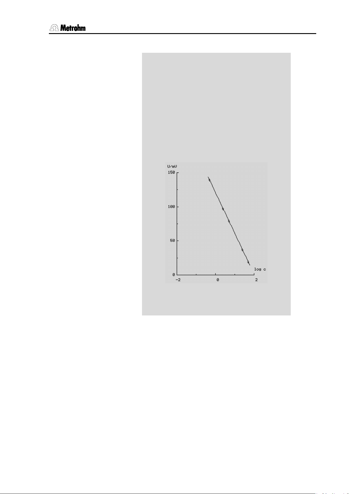
4 Show calibration data
• You can now display the calibration data with
If you move the selection bar to the end of the list with <
then in the line
Curve
you can activate the calibration curve display with
4 Print calibration report
• With
printer or a PC.
• With
tion report in the report selection list (cali
all the data except the calibration curve itself.
• The Select key
this also outputs the calibration curve.
.
you can now output a calibration report to a
you can jump directly to the short calibra-
offers the further option 'calib full';
or re-
.
>,
.
21
Page 32

3.1 pH measurement
780/781 pH/Ion Meter, Manual
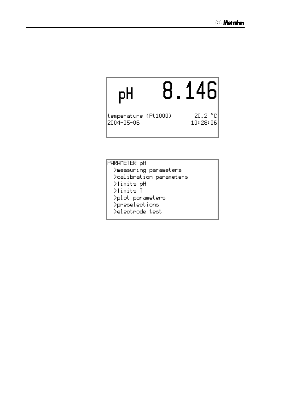
<STIRRER>
You can read off the actual pH of the sample from the display.
<MEAS/PRINT> you can start the output of a measuring
STI RRER
'mp
3.1.4 pH measurement
1 Select printout criterion
CONFI G
2
• If the obtained measured value is to be printed out directly as
a measuring point report or transferred to a PC then the required printout criterion must be set
(see Section 5.2):
CONFIG/print meas.value/print crit.: drift
2 Start measurement
• Immerse the pH electrode in the sample.
• Switch on stirrer with
.
3 Determine measured value
•
It is stable when the drift display
(small double arrow on the left-hand side) no longer blinks.
4 Print measurement
MEAS/
PRI NT
• With
point report on a printer or PC. The recording of the measurement and its output depend on the printout criterion 'Drift'
and take place only when the current drift condition is fulfilled
(see Section
781 pH/Ion Meter 01104 5.781.0020
date 2004-05-12 16:57:55
pH ******** run number 5
electr.id
#5 pH = 5.875 20.2 °C Pt1000
==============
6.2.1):
22
Page 33

3 Short operating tutorial
780/781 pH/Ion Meter, Manual
781 pH/Ion Meter (2.781.0010)
801 Magnetic Stirrer (2.801.0010)
).
Fluoride ISE (6.0502.150) with cable (6.2104.020)
Ag/AgCl reference electrode (6.0726.100) with cable (6.2106.020)
Temperature sensor (e.g. Pt 1000, 6.1110.100) with cable
(6.2104.140)
Fluoride standard solution (6.2301.030)
TISAB solution
TISAB
3.2 Determination of an ion concentration (only 781: Conc mode)
3.2.1 Requirements
Carrying out a calibration followed by the direct potentiometric determination of fluoride is described as an example. As this tutorial is only intended to provide a first introduction to ISE measurement with the 781
pH/Ion Meter, the automatic addition of the standard solutions is omitted in order to limit the number of accessories required. Further possible ways of carrying out a potentiometric fluoride determination, such
as the automatic addition of the standard for calibration or standard
addition, are described in Application Bulletin 82.
The following instruments, accessories and solutions are required:
•
•
Other stirrers can also be used (see Section
5.6
•
•
Electrolyte filling: inner and outer c(KCl) = 3 mol/L
•
•
c(NaF) = 0.1000 mol/L (1900 ppm F
•
NaCl, Na-acetate buffer pH 5.5; for preparation see below
3.2.2 Preparations
To prepare the
dist. water and add 57 mL glacial acetic acid. Adjust the pH of the buffer with 5 M NaOH to 5.5. Then make up the solution to 1 L with dist. water.
Prepare the following five fluoride standard solutions from the stock solution: 0.5, 2.5, 5.0, 25.0 and 50.0 ppm. All standards should consist of
a 1:1 mixture of dist. water and TISAB buffer.
Before you start this tutorial you must ensure that the instrument and
accessories have been correctly installed as described in Section 2.
The most important points concerning the installation are briefly given
again below (please refer to the Section mentioned for details). If you
are not certain whether all the settings (
correspond to the original conditions you can first reset any alterations
by initializing the memory (
-
)
solution dissolve 58 g NaCl in approx. 500 mL
CONFIG and PARAMETER Conc)
RAM Initialization) (see Section 8.5).
23
Page 34

3.2 Determination of an ion concentration (only 781: Conc mode)
780/781 pH/Ion Meter, Manual
<MODE>
<PARAM>
ppm
<SELECT>
5
PARAMETER Conc
PARAMETER Conc
1 pH/Ion Meter installation
• Set up instrument Section 2.1
• Connect stirrer Section 2.3.1
• Connect electrodes Section 2.4
• Mains connection Section 2.5
2 Initial configuration
ON/ OFF
• Switch on pH/Ion Meter Section 5.4
• Set dialog language Section 5.4
• Set date/time Section 5.4
CONFI G
• Set temperature sensor Section 5.4
3.2.3 Calibrating the fluoride ISE
1 Set method parameters in the Conc mode
MODE
• Press
to enter the Conc mode
PARAM
• In the ion parameters (
to
with
> ion parameters
conc.unit: ppm
:
) set the concentration unit
• In the calibration parameters set the number of standards to
and define the concentrations:
> calibration parameters
no. of standards 5
addition: manual
conc.1 0.5 ppm
conc.2 2.5 ppm
conc.3 5.0 ppm
conc.4 25.0 ppm
conc.5 50.0 ppm
24
Page 35

3 Short operating tutorial
780/781 pH/Ion Meter, Manual
<CAL>
<ENTER>
<ENTER>
<ENTER>
<ENTER>
<ENTER>
<ENTER>
2 Start calibration with first standard
CAL
• Immerse electrodes in the standard with the lowest F- concen-
tration
ENT ER
• Start calibration with
• If no temperature sensor is connected:
enter the temperature and exit with
• Confirm standard concentration with
or – if neces-
sary– correct it
• Wait for measurement of the potential
3 Continue calibration with increasing standard con-
centrations
• When the request 'Change std.
' appears, remove
the electrodes from the first standard, rinse them with water
and blot them gently with a clean lint-free tissue
• Immerse electrodes in the next standard and continue the cal-
ibration sequence with
• In each case conform the standard concentration with
or – if necessary – correct it
• Repeat procedure for each remaining standard
4 Result
• Wait for potential measurement, result will be displayed:
ENT ER
• After 30 s the pH/Ion Meter will switch back automatically to
the measurement display. This can also be done immediately
with
.
25
Page 36
3.2 Determination of an ion concentration (only 781: Conc mode)
780/781 pH/Ion Meter, Manual
responding message will
<ENTER>,
<MODE>
<CAL.DATA>
< -> >
<->>
<REPORT>
<CAL.DATA>
tion report in the report selection list (calib short); this contains
<->>
CAL. DA T A
REPORT
9
5 Poor calibration data
• If the calibration data lies outside certain limits
(slope ≤ 80% or ≥ 105% of the theoretical slope of 59.16 mV
(25°C) per ionic charge) or the sign of the slope does not
agree with the selected ion type a cor
be shown:
ENT ER
MODE
• You can still accept the calibration data with
ject it with
.
or re-
7
6 Show calibration data
• You can now display the calibration data with
If you move the selection bar to the end of the list with <
then in the line
Curve
you can activate the calibration curve display with
7 Print calibration report
• With
printer or a PC.
• With
all the data except the calibration curve itself.
• The Select key
this also outputs the calibration curve (see Section 7.2.4).
you can now output a calibration report to a
you can jump directly to the short calibra-
offers the further option 'calib full';
.
>,
.
26
Page 37
3 Short operating tutorial
780/781 pH/Ion Meter, Manual
'fc
781 pH/Ion Meter 01104 5.781.0010
date 2004-05-13 09:20:50
Conc ******** run number 1
electr.Id
conc.calibration
ion type F(-1)
temperature 22.7 °C
temp.sensor Pt1000
c.dat. 2004-05-12 09:32
conc/ppm U/mV dconc/%
std. 1 5.00E-01 139.9 0.2
std. 2 2.50E+00 97.0 0.1
std. 3 5.00E+00 78.8 -0.6
std. 4 2.50E+01 37.1 -0.2
std. 5 5.00E+01 19.2 0.4
variance 0.014
slope -59.9 mV
E(0) 120.8 mV
c(blank) 0.00E+00 ppm
==============
27
Page 38

3.2 Determination of an ion concentration (only 781: Conc mode)
780/781 pH/Ion Meter, Manual
<PARAM>
<STIRRER>
can only be set when a Metrohm 8XX Stirrer is
<PARAM>
<STIRRER>
STI RRER
PARAMETER Conc
PARAMETER Conc
3.2.4 Direct measurement of fluoride
10 mL of the sample solution (e.g. 10 g table salt in 100 mL dist. water)
is also treated with 10 mL TISAB solution. This should first be diluted
1:1 with dist. water. This produces the calculation parameters which are
to be defined (see Section 6.5.4). As the measurement of the ions is
carried out unstirred, the stirrer is only used before the measurement to
ensure that the sample solution is properly mixed.
1 Set method parameters
PARAM
• In the Conc Mode define the stirrer control as a measuring pa-
rameter (
). Additionally the stirrer can also be
switched on and off manually before the measurement with
.
:
> measuring parameters
: :
stirrer: control
stirring rate 5
prestir pause 0 s
stir time 15 s
poststir pause 5 s
2
The stirring rate
connected to the MSB interface.
• The calculation parameters (
:
> calculation parameters
: smpl.size 10.0 mL
V total 20.0 mL
factor 1.0
smpl.size unit: mL
) are then:
2 Determine measured value directly
• Immerse electrodes in the sample.
• Switch on stirrer with
and – after sufficient time
has elapsed – off again.
• Wait until the electrodes have stabilized; i.e. until the drift sig-
nal in the display no longer blinks.
• Read off the value. This gives the fluoride concentration of the
sample solution without the addition of TISAB.
28
Page 39

3 Short operating tutorial
780/781 pH/Ion Meter, Manual
<MEAS/PRINT>
'mp
3 Print out measured value
MEAS/
PRI NT
• With
you can start the measuring sequence
(controlled stirring) and the output of a measuring point report
on a printer or PC. The recording of the measurement and its
output depend on the printout criterion 'Drift' and take place
only when the current drift condition is fulfilled (see Sec-
tion 6.2.1):
781 pH/Ion Meter 01104 5.781.0010
date 2004-05-13 09:45:24
Conc ******** run number 12
electr.id
smpl.size 10.0 mL
ion F(-1)
#1 c = 25.7 ppm 23.6 °C Pt1000
==============
29
Page 40

3.2 Determination of an ion concentration (only 781: Conc mode)
780/781 pH/Ion Meter, Manual
30
Page 41

4 Operation
780/781 pH/Ion Meter, Manual
4 Operation
4.1 The keypad
• Universal functions • Input of numbers and text
• Navigation
• Special functions
The keys beneath the display can be triggered from the measured value display irrespective of the mode.
Most of the keys on the right-hand side have two functions: The numbers to be entered and the navigation functions are shown in the center
of the keys; the additional functions at their upper margin.
31
Page 42
4.2 Operating concept
780/781 pH/Ion Meter, Manual
1.
measured value display.
2.
menu display
measured value display
<MEAS/PRINT>
<ENTER>
<MODE>
menu display with <CONFIG>
<PARAM>
<PARAM>
<CONFIG>
4.2 Operating concept
The pH/Ion Meter provides two types of display:
The
The
This is the normal instrument display.
This is used for editing various settings.
In the directly measuring working modes the current measured value is
shown together with the date and time in the
the Conc mode the method name and the type of ion selected are also
shown. If the result is to be printed out, or if a stirring sequence or the
entry of sample identifications (Id) are intended for recording a measured value, then this is started with
with standard or sample addition or subtraction the last result to be determined is always shown. In this case a measuring sequence is started
with
ing mode of the pH/Ion Meter is changed with
easily see which mode is set from the measuring unit or the prefix 'pH'
shown in the display.
In each operating mode you can switch from the measured value display to the
the instrument configuration and the method parameters to be edited.
In the direct measuring modes measurement recording and evaluation
(e.g. automatic printing and limit monitoring) continues in the background. In the menu display it is also possible to change directly from
the configuration to parameter input with
with
. The measured value display changes when the operat-
.
. In the Conc mode
or
. You can
. This allows
and vice versa
. In
32
Page 43

4 Operation
780/781 pH/Ion Meter, Manual
ON/ OFF
<ON/OFF>
<ON/OFF>
CONFI G
<CONFIG>
<REPORT>
<CONFIG>
PARAM
<PARAM>
<REPORT>
<PARAM>
CAL
<CAL>
MEAS/
PRI NT
<MEAS/PRINT>
• Depending on the configuration (see
4.3 All key functions at a glance
The functions of all the keys are described below both for the measured
value display and the menu display:
Key Measured value display
(normal operation)
On/Off switch
• The
instrument on and off
• This applies even if the lamp of the
LCD display is switched off!
(see Section 5.4)
• After switch-on the pH/Ion Meter is in
the normal operation display of the last
mode to have been used
key switches the
Opens configuration menu
•
for the instrument configuration.
• These configuration settings remain
unchanged until they are edited or the
permanent memory of the instrument
configuration is initialized (see Sec-
tion 8.5).
opens the selection menu
Report selection
• Direct selection of the configuration
report after
.
Menu display
(editing)
On/Off switch
• The
instrument off at any time.
key switches the
Changes to configuration
menu
• The
switch directly from the parameter
menu to the selection menu for instrument configuration.
key can be used to
Opens parameter menu
• The
tion menu for the method parameters.
• All parameter settings belong to a
method and are stored methodspecifically with this method.
key opens the selec-
Report selection
• Direct selection of the configuration
report after
.
Starts calibration
• In the pH and Conc (direct) modes the
key starts a calibration.
Starts measurement / Prints
out measured value
• In the pH, T, U and Conc(direct)
modes the
gers a measuring sequence.
key trig-
Changes to parameter menu
• With the
switch directly from the configuration
menu to the parameter menu.
key you can
33
Page 44

4.3 All key functions at a glance
780/781 pH/Ion Meter, Manual
<MEAS/PRINT>
MODE
<MODE>
<MODE>
QUI T
<QUIT>
<QUIT>
<QUIT>
CAL. DA T A
<CAL.DATA>
<REPORT>
USER
8
<USER>
REPORT
9
<REPORT>
<SELECT>
<CAL.DATA>
ADD. DA T A
4
<ADD.DATA>
Key Measured value display
(normal operation)
Section 5.2), the
prints out the measured value as a
measuring point report.
Operating mode selection
• In the pH, T and U modes (780 pH
Meter) and the pH, T, U and Conc
modes (781 pH/Ion Meter) the
key changes the mode.
Message acknowledgement
• Displayed messages are normally
acknowledged with
tions: see Section 8.2)
• If cause of the message has not been
remedied then it will appear again at
the next check.
Displays calibration data
7
• In the pH and Conc(direct) modes the
calibration data.
key shows the current
key
. (Excep-
Menu display
(editing)
Cancels sequence
• With the
quences are terminated without direct
transfer of the data.
key working se-
Cancels working step
• Queries are exited with
this way it possible, e.g. to skip individual steps within a working sequence
without accepting the data.
• In menus
the next higher level.
causes a jump to
Enters the number '7'
. In
Report selection
• Direct selection of the configuration
report after
.
User selection
• With
newly entered, selected or deleted.
a user name can be
Report selection and printout
• With
selected and printed out.
• The selection of the report from those
available is made either with
corresponding key (e.g.
Report selection).
a report can be
or directly by pressing the
, see right-hand column:
Shows addition data
(781 pH/Ion Meter only)
• In the Conc Mode
shows the data of the last measurement for standard and sample addition
methods.
Enters the number '8'
Enters the number '9'
Enters the number '4'
34
Report selection
(781 pH/Ion Meter only)
Page 45
4 Operation
780/781 pH/Ion Meter, Manual
•
<REPORT>
ST ORE
5
<STORE>
<MEAS/PRINT>
RECA L L
6
<RECALL>
<REPORT>
EL. TEST
1
<EL.TEST>
<REPORT>
STI RRER
2
<STIRRER>
M ET HODS
3
<METHODS>
<REPORT>
0
Key Measured value display
(normal operation)
Direct selection of the short result
report after
.
Stores measured value
• In the pH, T, U and Conc(direct)
modes the
measuring sequence and stores the
measured values in the memory in a
similar manner to
• The storage criterion must have been
previously defined under
CONFIG /Store meas. value.
key triggers a
Opens measured value
memory
• The measured value memory is
opened with the
stored measured values can then be
viewed or deleted.
Report selection
• Direct selection of the measured value
memory report after
Menu display
(editing)
Enters the number '5'
.
Enters the number '6'
key. The
.
Starts electrode test
• In the pH mode you can start an elec-
trode test with the
key.
Report selection
• Direct selection of the pH electrode
test report after
.
Stirrer on/off
• A connected stirrer can be switched
on and off manually with the
key.
Method selection
• With the
tion for loading, saving or deleting a
method is opened (see Section 6.1).
key the selec-
Report selection
• Direct selection of the method memory
report after
.
Enters the number '1'
Enters the number '2'
Enters the number '3'
Enters the number '0'
35
Page 46

4.3 All key functions at a glance
780/781 pH/Ion Meter, Manual
ABC
.
<.>
<ABC>
<-
/exp>
<-/exp>
SEL ECT
SEL ECT
<SELECT>
<ENTER>
Key Measured value display
(normal operation)
-/ exp
and
Menu display
(editing)
Enters a decimal point '.'
• The
the input field.
key enters a decimal point in
Exception: open text editor
• If the
input field where text input is possible
then a text input box for editing the text
will be opened.
key is first pressed in an
Enters a minus sign '-'
• If you start a numerical input with
then the numerical value to be
entered will receive a minus sign.
Enters an exponent 'E'
• When a numerical input has been
started then the
vide an exponential notation.
key will pro-
Selects predefined entries
• For menu parameters which offer a
fixed choice of settings (recognizable
by the final colon) the selection list can
be viewed with the
The arrows determine the selection direction.
- keys.
Cursor control for text input
• In the text editor the arrow keys are
used to select the character to be entered and the
it.
key to enter
36
Page 47
4 Operation
780/781 pH/Ion Meter, Manual
CONTRAST+
CONTRAST -
<CONTRAST+>
<CONTRAST->
<>
<>
<ENTER>
<>
CLEAR
<CLEAR>
<CLEAR>
<CLEAR>
<CLEAR>
ENT ER
<ENTER>
and
Alters display contrast
• The contrast of the LCD display can
be altered with the
and
measured values display.
• This setting is retained after the in-
strument has been switched off and
on. The default value is only reset after
the memory has been initialized.
keys during the
Controls the menu bar
• In each menu display the
keys can be used to move the
selection bar up and down by one line.
Cursor control for text input
• In the text editor the arrow keys are
used to select the character to be entered and the
it.
Leafing between entries in
the measured values memory
• Leafs between the entries in the
measured values memory display:
starting from the last measured value
to be stored you can access older entries with
• At the beginning and end of the list
you can use the corresponding arrow
key to jump directly to the other end of
the list.
and vice versa.
and
key to enter
Deletes text input
• Before opening the text editor during
text input the
the complete entry. Within this box
deletes the character to the
left of the cursor.
key will delete
Shows special value
• If a special value exists for an entry or
selection then this can be shown with
the
key.
Shows standard value
• All other entry and selection possibili-
ties provide the standard value with the
key.
Confirms entry
• The
plete each entry with the selection bar
moving on to the next parameter. If an
entry is exited without this confirmation
then the entered value will be rejected.
key is used to com-
37
Page 48

4.4 Operating principles
780/781 pH/Ion Meter, Manual
PARAMETERS
<CONFIG>
<PARAM>
<>
<>
<ENTER>
<QUIT>
<ENTER>
<QUIT>
<ENTER>
<ENTER>
Entries with a fixed selection
<SELECT>
<ENTER>
<CLEAR>
Entries which can be edited
<ENTER>
Numbers
<-/exp>
SEL ECT
SEL ECT
4.4 Operating principles
4.4.1 Configuration and method parameters
Instrument configuration and method parameters are each contained in
menus with a tree structure. These menu structures are shown in the
Annex in Section 9.3.
The instrument configuration of the pH/Ion Meter is described in the
CONFIG menu. This contains the basic settings that apply for all the
selected working modes and methods. The method parameters are
stored under
od parameters depend on the measuring mode which has been set.
The change from the measured value display to the menu display is
made by using the
submenu appears first, and is shown with an '>' (e.g. >Measuring
parameters). You can now move the selection bar up and down with
and
the
arrow keys. Each underlying level in the menu
structure is opened with
tions to individual entries must be confirmed with
terations are exited with
. In contrast to the configuration, the meth-
or
and exited with
then they remain ineffective.
keys. The title of the
. If such al-
. Altera-
If an entry is confirmed with
to the next entry. At the end of a submenu it will finally change to the
next point of the superior menu selection.
In this way you can run through the complete menu structure for the
configuration and parameters by repeatedly pressing the
key. This can be helpful when carrying out checks.
Not all parts of the menu structure described below are visible in the
display at all times. Only the specific possible settings of the option
which is currently activated are shown. For example, the various settings for printing out the measured values under
values/print crit.
tivated completely (OFF). If one of the other printing criteria is selected
then the particular settings it requires will appear in the display.
4.4.2 Editing menu entries
A basic differentiation is made between two types of menu entry.
dialog: english, deutsch, français, español
The selection is then made with the
with
print, can be shown by pressing
then the selection bar will move
CONFIG/print meas.
are not visible when printing has been deac-
are indicated by a colon:
keys and confirmed
. The default setting, which is normally shown in bold
.
ENT ER
confirming it with
are entered directly with the number keys. Exponential
notation can be activated directly with the
38
are altered by entering a new value and
.
key.
Page 49

4 Operation
780/781 pH/Ion Meter, Manual
<QUIT>
<CLEAR>
<ENTER>
Text entries
<ABC>
<CLEAR>
<EN-
TER>
<CLEAR>
<QUIT>
<ENTER>
<QUIT>
ABC
Values outside the valid range of limits for the particular
entry will not be accepted by the instrument. This is indicated by the invalid entry blinking. You can now either
enter a new value or retain the original value by exiting
with
Special entries exist for some numerical entries; these
cannot be seen directly and cannot be edited (e.g.
'OFF' for the measuring parameter Drift). These can be
shown with
.
and confirmed with
.
4.4.3 Entering text
You can use
the input of alphanumeric characters:
.
This text editor must be called up right at the start of a new entry after
the old entry has been completely deleted with
sary. If a text input is started directly with numbers from the number
block of the keyboard then the subsequent opening of the text editor is
no longer possible.
The required characters are selected with the arrow keys. The cursor
movement can be accelerated by keeping the arrow keys pressed
down. The marked character is accepted in the input field with
that there free places are available. Otherwise you can delete individual
characters from the back with
are made using the text editor and are described in the
following section.
. A requirement is that a blinking cursor in the input field indicates
to open a text editor for entering texts; this allows
.
, if neces-
Text input is terminated by exiting the text editor with
firming the entry with
jected then
must be activated a second time.
. However, if the whole entry is to be re-
and con-
39
Page 50

4.4 Operating principles
780/781 pH/Ion Meter, Manual
40
Page 51

5 Configuration
780/781 pH/Ion Meter, Manual
<CONFIG>
<CLEAR>
<CLEAR>
5 Configuration
CONFI G
With the
contains all the instrument settings for the pH/Ion Meter. These are independent of both the mode and the method. This means that they
cannot be stored separately like the method parameters (see Sec-
tion
memory containing the instrument configuration is re-initialized (see
Section 8.5).
All the settings of this menu are described in this section. English is
used as the dialog language. For each point you will find all the possible entries or the valid entry range together with the default value. This
will always be reset when the permanent memory of the pH/Ion Meter is
re-initialized. During the input you can also deliberately call up the default value with
Example:
time interval 1,2,3...365...9999 d
This setting defines a time interval in days. In this example it is the time
after which the validation of the instrument is to be carried out (
toring/validation
and 9999 or call up the default value of 365 days with
6). They continue to exist until they are edited or the permanent
key you can access the configuration menu. This
. It is shown in bold type below.
). You can either enter whole numbers between 1
>moni-
.
41
Page 52

5.1 Report
780/781 pH/Ion Meter, Manual
REPORT
9
└
Report Id:
'mp
Instrument Id:
781 pH/Ion Meter 5.781.0020
Date, Time:
Datum 2004-05-24 09:50:56
User *:
user C. Weber
Mode / Method / Run number:
pH pH-1 run number 9
Electrode Id:
electr.id pH electr.1
Sample Id1:
id1 batch 21
Sample Id2:
id2 sample A01
Signature:
Signature ________________________
<USER>
5.1 Report
CONFIG
├ report
│ ├ id1
: ├ id2
├ report id
├ instrument id
├ date & time
├ method
├ electrode id
├ signature
In the configuration menu report you can define the output format of
the report header. This describes the first lines of a measuring point report (see also Section 7.2.3) and can be either placed in front of each
measured value to be printed out or before a series of measured values
(see following section).
A report header containing all the elements described here could look
like this:
line feed
*The 'user' line is not configured here. The entry of a user name takes
place automatically when a user has been defined with the
key. The name remains active until it is deleted or another user name is
selected (see Section
id1, id2 (max. 16 characters)
This is where you can define short texts as additional information for the
report header. Each of these entries will be printed out in a single line in
each report. In addition, you can also request these Ids before each
measurement as a preselection (see method parameter
tions
report id: ON, OFF
This setting defines whether the report Id is to be printed out in the first
line of the report header. It is used to identify the report.
instrument id: ON, OFF
You can include the instrument identification in the report header if you
want to. It consists of the exact type name of the pH/Ion Meter with the
version number of the instrument software.
in Section 6), e.g. in order to mark each sample specifically.
4.3).
preselec-
42
Page 53

5 Configuration
780/781 pH/Ion Meter, Manual
<METHODS>
<CLEAR>
An additional way of assigning report printouts to a particular instrument is by using an individual instrument name under
FIG/auxiliaries/device label
(see Section 5.4). This will then be
CON-
printed out automatically in a separate line in the report header after the
instrument Id.
date & time: ON, OFF
This setting defines whether the date and time of the report printout are
to be printed. The date and the exact time of the measurement can additionally be printed with each successive measured value (see following section).
method: ON, OFF
As well as the mode name, the name of the method used can also be
printed out in the report header if required. You can define this previously by storing the method parameters used with
. If no
method name has yet been defined then the character sequence
******** will appear.
electrode id: ON, OFF
You can include the electrode name in the report header if you have defined an electrode ID for the currently valid calibration. Otherwise this
field in the report header will remain empty.
signature: ON, OFF
Reports which contain measuring data (measuring point, addition, calibration and electrode test reports) can, depending on the configuration,
have a signature line added on. In this way the result can be provided
with a signature.
line feed form, 0,1,2,3...999
The paper feed of the printer at the end of a report can be set here.
With continuous paper printers (e.g. Custom) you can select the number of empty lines so that after the report has been printed out you can
tear off the printed paper directly at a suitable point. For single page
printers (e.g. HP DeskJet) you can enter the special value '
so that the printed page will automatically be produced by
form' with
the printer after each report.
43
Page 54

5.2 Printing out measured values
780/781 pH/Ion Meter, Manual
MEAS/
PRI NT
└
<MEAS/PRINT>,
immediate-
ly
time
drift
plot
<MEAS/PRINT>
5.2 Printing out measured values
CONFIG
:
├ print meas.value
: └ print crit ┬ immediate ┬ date & time
│ ├ report header
│ └ calibration report
├ time ┬ date & time
│ ├ report header
│ ├ calibration report
│ ├ time interval
│ └ stop time
├ drift ┬ date & time
│ ├ report header
│ └ calibration report
├ plot ┬ time interval
│ ├ time scale
│ ├ time scale label
│ └ stop time
OFF
In the configuration menu print meas.values the output form of
measured values, triggered by
possible for the direct measuring modes pH, T, U and Conc(direct).
print crit: immediate, time, drift, plot, OFF
Depending upon the print criterion a measured value report with be
transmitted via the RS232 interface to a printer or PC either
, at defined
filled. If a stirring sequence is intended before the measurement (
RAMETERS/measuring parameters/stirrer: control,
6), then these print criteria will only be effective when the stirring
tion
sequence has been concluded.
A further way of documenting the measured values is to output a
graphical
print crit.: immediate
With this setting a measured value report will be produced when
following options can be used:
date & time: ON, OFF
intervals or only when a
of the measure value signals.
is activated from the normal instrument display. The
is defined. This is only
condition has been ful-
PA-
see Sec-
44
Here you can choose whether the date and time at which the
measured value was recorded are to be included with each individual measured value. This can take place irrespective of whether a report header is used.
report header: once, always, OFF
Page 55

5 Configuration
780/781 pH/Ion Meter, Manual
<QUIT>
Normally each measured value is accompanied by the report
header for documentation purposes. The exact contents of the
report header are defined under CONFIG/Report (see above).
With a larger series of manually triggered measurements it may
be advisable to print out the report header only once with the first
measured value. In this case all the measurements should be
made under the same conditions. The report header will only appear again when the run number has been reset to zero by
switching the instrument off and on.
calibration report: ON, OFF
You have the possibility of providing each measured value with
the associated calibration data of the electrode used, e.g. within
the context of a GLP documentation.
print crit: time
With this print criterion you can automatically record and output the
measured values at fixed intervals. The following options are used:
date & time: ON, OFF
report header: once, always, OFF
calibration report: ON, OFF
These settings correspond to those of the print criterion 'immediate' (see above).
time interval: 0.1...4.0...99999.0 s
Automatic measuring value recording can be carried out at time
intervals of down to 0.1 s. Please note that if small time intervals
are used then the amount of data for each measured value must
be adapted accordingly, as otherwise the buffer memory of the
connected printer or PC would be filled too quickly. This means,
for example, that the report header should only be printed out
once at the start of a series of measurements. Otherwise data
could be lost at the RS232 interface of the receiver. In this case
you should consider matching the measured value recording interval to the measured value memory (see Section 5.3).
stop time: OFF, 1...999999 s
The time after which an automatic series of measurements is to
be terminated can be entered in whole seconds. You can also let
a series of measurements run indefinitely without a fixed stop time
and then stop it manually with
if you select 'OFF' for this
setting.
45
Page 56

5.2 Printing out measured values
780/781 pH/Ion Meter, Manual
<QUIT>
print crit.: drift
If this print criterion is used then a measured value will only be documented when the drift condition defined under
ing parameters/drift
has been fulfilled.
PARAMETERS/measur-
date & time: ON, OFF
report header: once, always, OFF
calibration report: ON, OFF
These settings correspond to those of the print criterion
immediate' (see above).
'
print crit.: plot
The directly recorded values can be outputted graphically as a measured value/ time plot.
time interval: 0.1...4...99999.0 s
In a similar way to the print criterion 'time' a time interval can be
defined for graphical measured value recording.
time scale: 5,10,30,60,120,180..99960
This is the time axis scale. The reciprocal value of the quantity entered corresponds to the paper feed rate. This means that, e.g.,
for a required feed rate of 2 cm/min a time scale of ½ min/cm =
30 s/cm must be entered.
time scale label.: rel, abs
The time axis scale can use the relative time in minutes and seconds (start = 0 s). The current time can also be used with '
stop time: OFF, 1...999999 s
The graphical plot is terminated when the stop time has elapsed
or will continue indefinitely ('
possible with
.
OFF'). In both cases termination is
s/cm
abs'.
46
Page 57

5 Configuration
780/781 pH/Ion Meter, Manual
ST ORE
└ stop time
<STORE>
<STORE>
<RECALL>
5.3 Storing measured values
CONFIG
5
:
├ store meas. value
: └ store crit ┬ immediate, drift, OFF
└ time ┬ time interval
In the direct measuring modes pH, T, U and Conc(direct) you can use
mation in the instrument memory (see Section
settings to be defined under
to those made under
store crit: immediate, time, drift, OFF
This storage criterion also only becomes effective when an optional stirring sequence has been concluded.
In contrast to the report output, the combination of the information
stored together with each measured value is fixed.
to store up to 100 measured values with additional infor-
CONFIG/store meas. value correspond
CONFIG/print meas. value:
7.3). The functions of the
store crit: immediate
The current measured value is stored with
store crit: time
time interval: 0.1...4.0...99999.0 s
stop time: OFF, 1...999999 s
You can automatically record and save the measured values at fixed
time intervals until the stop time has been reached.
store crit: drift
A measured value can also be stored when the drift condition defined
under
After 100 measured values have been stored, and each time a further
storage attempt is made, the pH/Ion Meter will produce a corresponding warning:
You now have the possibility of using
measured values, of deleting individual measured values or of clearing
the whole measured value memory (see Section
to output all measured values as a report via the RS232 interface (see
Section 7.2.8).
PARAMETERS/measuring parameters/drift has been fulfilled.
measured value memory full
7.3). It is also possible
.
to view the stored
47
Page 58

5.4 Auxiliaries
780/781 pH/Ion Meter, Manual
└ program
5.4 Auxiliaries
CONFIG
:
├ auxiliaries
: ├ run number
├ last digit
├ dialog
├ display
├ LCD off after
├ date
├ time
├ time zone
├ temp.sensor
├ temp.unit
├ device label
├ beep
Various basic settings for the configuration of the pH/Ion Meter are
made in this submenu.
run number 0,1,2,3...999, OFF
The run number is included in the report. It is increased by one after
each measuring process. This applies to both the storage of measured
values and to the calibration or pH electrode test and makes the later
chronological assignment of such different measuring processes easier.
When the instrument is switched on the run number is automatically set
to '0'. The first measuring process begins with '1'.
last digit: ON, OFF
This setting can be used to conceal the last decimal place of the measured value display. The displayed value is rounded off accordingly. This
can be useful in improving the readability of a rapidly changing measured value. Please note that this setting does not influence the drift control of a measurement.
dialog: english, deutsch, français, español
The dialog language covers both the language shown on the display
and that used in the report. Switch the instrument off and on if this setting has been changed.
48
display: positiv, negativ
You can choose whether you want to have a positive or negative display presentation, e.g. in order to adapt it to the local lighting conditions.
Page 59

5 Configuration
780/781 pH/Ion Meter, Manual
<ON/OFF>
<ON/OFF>
<QUIT>
LCD off after 1,2...999 min, OFF
The display of the pH/Ion Meter has an illuminated background. In order to increase the working life of the lamp you can switch off the display automatically when the instrument has not been used for a certain
time. Please note that, if the lamp is switched off and on too frequently
then its working life will also be reduced. This means that times of about
30 min can be recommended.
The fact that the LCD illumination is switched off does not affect the
functioning of the pH/Ion Meter in any way. It continues to work normally. The lamp can be activated again with any key except
Please note that the
key switches the instrument off. All
other keys only have the function of activating the LCD illumination. This
means, for example, that runs will not be terminated when the
key is used to reactivate the background illumination.
date YYYY-MM-DD
time hh:mm:ss
You can set the date and time here. The program will only accept numbers which make sense.
.
time zone 12 ASCII characters
For complete documentation you can add details of the time zone to
the time information for output in the report header. The input of up to
any 12 characters is possible. Examples: 'MEZ', 'UTC-05:00'
(Coordinated Universal Time minus 5 h) or location of the measurement.
temp.sensor: Pt1000, NTC
The 780/781 pH/Ion Meter supports the use of two different types of
temperature measuring techniques T: Pt1000 (platinum resistance
thermometer) and NTC ('Negative Temperature Coefficient' semiconductor). This means that the configuration must be adapted accordingly. If NTC sensors are used then it is also necessary to enter two sensor
characteristics; these can be found in the specification of the sensor:
R(25 °C) 10000...30000...100000
B value 1000...4100...9999
The standard values R(25 °C) = 30000 ohm and B value = 4100 K apply to the use of a Metrohm electrode with NTC sensor (e.g. 6.0228.010
LL Solitrode NTC), where the B value refers to 25 °C and 50 °C. B values of other NTC sensors are frequently based on different reference
temperatures (usually 25 °C / 50 °C – 100 °C). When entering your own
sensor characteristics the effect of the second reference temperature
on the measuring accuracy of an NTC sensor is negligible.
49
Page 60

5.4 Auxiliaries
780/781 pH/Ion Meter, Manual
temp.unit: C, F
The pH/Ion Meter can work with temperature information in both °C and
°F units.
Please note that, when changing this setting, the default value of the
measuring parameter drift in the T mode has the unit °C and, if necessary, must be converted as follows:
TF = 32 + 1.8 ·TC or TC = (TF – 32)/1.8
TF: temperature in °F
: temperature in °C
T
C
device label 12 ASCII characters
If apart from the instrument Id you wish to assign a further name to a
particular pH/Ion Meter for inclusion in the report then you can enter
your text here, e.g. '
Lab 2.01' or 'Works 2'. This will then be included in
the report header in a separate line inserted after the instrument Id.
beep: OFF,1,2,3
Messages on the display of the pH/Ion Meter are accompanied by a
beep. This can be switched off completely or just limited to a sequence
of 2 or 3 beeps.
program
This is the version number of the instrument software and cannot be altered. It is included in the report header as part of the instrument Id.
50
Page 61
5 Configuration
780/781 pH/Ion Meter, Manual
└ system test report
<CLEAR>
<CON-
FIG>
SETUP
5.5 Monitoring
CONFIG
:
├ monitoring
: ├ validation
├ service
The 780/781 pH/Ion Meter can inform you automatically about reoccurring quality monitoring tasks.
validation: ON, OFF
If this option is active then you can enter a time interval in days and,
when it has elapsed, the instrument will request you to carry out a validation process.
In addition, the time counter shows the elapsed time in days since the
last time that this option was switched on. When the time counter
reaches the set number of days then the following message will appear:
time interval 1...365...9999 d
time counter 0 d
validate instrument
This will also be included in the report header. It can only be removed in
the following ways:
• Resetting the time counter to zero under
validation
• Extending the time interval and then switching the instrument off
and on again
• Switching off the validation monitoring option
In order to prevent unauthorized removal of the message the
key can be disabled under the instrument
7.5.1), so that the settings described above are no longer accessi-
tion
ble.
service: ON, OFF
next service YYYY-MM-DD
At a particular time the instrument can remind you about the date when
a service is due. When the set date has been reached the following
message appears on the display:
with
service is due
CONFIG/monitoring/
(see Sec-
This is also included in the report header and can be switched off by either entering a new and later service date or by switching this monitoring function off.
51
Page 62
5.6 Peripheral units
780/781 pH/Ion Meter, Manual
└
<STIRRER>
system test report: ON, OFF
When it is switched on the 780/781 pH/Ion Meter automatically carries
out a system diagnosis. The result can be outputted as a system test
report (see Section 8.4.1).
5.6 Peripheral units
CONFIG
:
├ peripheral units
: ├ character set
├ Dosimat
├ stirrer
├ keyboard
barcode
Various peripheral units can be connected to the 780/781 pH/Ion Meter.
The corresponding configurations must be carried out here.
character set: IBM, Epson, Seiko, Citizen, HP
The type of printer chosen for the report printout is selected here. If you
have connected a PC to the RS 232 interface for data reception then
set this parameter to '
IBM'.
Dosimat: 665, 725, 765, 776
The 781 pH/Ion Meter can be used to control a Metrohm Dosimat Plus,
e.g. for the automated production of standard solutions for the calibration of ion-sensitive electrodes. Analyses involving the addition of
standard and sample solutions can also be automated in this way. In
order to control an 865 or 876 Dosimat Plus, make sure that the
Dosimat 665 is selected. Please note the required settings at the
Dosimat Plus (see Ch. 2.3.3).
stirrer: 8xx, 7xx
Metrohm stirrers of the series 8xx and 7xx can be connected to the
pH/Ion Meter. In order to connect 7xx series stirrers the use of a remote
box (6.2148.010) at the MSB connection of the pH/Ion Meter is necessary (see Section 9.5
switched on and off from the pH/Ion Meter with
). For example, both types of stirrer can be
. With 8xx
series stirrers the stirring rate can also be controlled from the pH/Ion
Meter (see
are using a stirrer of another manufacturer, then you must select
PARAMETERS/measuring parameters/Stirrer). If you
'7xx'.
keyboard: US, deutsch, français, español,
schweiz.
If texts have to be entered frequently it may be a good idea to connect
a PC keyboard. The language-specific keyboard layout is then set here.
Older PC keyboards may possibly have a too-high power consumption,
which could result in the cancellation of the system test when the in-
52
Page 63

5 Configuration
780/781 pH/Ion Meter, Manual
strument is switched on. In such a case remove the connected keyboard and switch on the instrument again.
53
Page 64

5.7 RS232 settings
780/781 pH/Ion Meter, Manual
└
barcode: input, id1, id2
For data input you can also use a barcode reader which provides a
PS/2 connection. Older barcode reader may possibly have a too-high
power consumption, which could result in the cancellation of the system test when the instrument is switched on. In such a case remove the
connected keyboard and switch on the instrument again.
5.7 RS232 settings
CONFIG
:
└ RS232 settings
├ baud rate
├ data bit
├ stop bit
├ parity
handshake
For communication with instruments (printer, PC) connected to the serial RS232 interface the correct setting of these parameters is required:
baud rate: 38400, 19200, 9600, 4800, 2400, 1200,
600, 300
data bit: 7, 8
stop bit: 1, 2
parity: even, none, odd
handshake: HWs, SWChar, SWline, none
Please refer to the manual of your printer for the exact settings. When a
computer is connected the corresponding configuration can usually be
carried out in the terminal program used.
54
Page 65

6 Methods / Parameters
780/781 pH/Ion Meter, Manual
<METHODS>
└ delete method
<ABC>
<SELECT>
M ET HODS
6 Methods / Parameters
The exact measuring method of the pH/Ion Meter is described by
method parameters which, like the instrument configuration, are arranged in a tree structure in the menu display. The complete tree is
shown in the Annex (see Section 9.3) to provide a better overview.
The parameters are set in a similar way to the instrument configuration.
In contrast, however, the administration of the method parameters is
mode-specific. The selection of the method parameters also varies with
the selected mode. For this reason the method parameters for each
mode are described separately in this section.
This means that one of the following subsections, together with the instrument configuration, forms a complete description of all the settings
which are important for the operation of the pH/Ion Meter in a particular
measuring mode.
Please note that editing numerical values with more than 7 digits can
result in rounding effects. In this case, consider the exponential notation or a different concentration unit (see Section 6.5.2, 781 only).
6.1 Method management
Press
3
as a method. You can also load or delete methods within this dialog.
METHODS
├ recall method
├ store method
For each selection you can edit a method name with
one with
All saved methods are accessible in all modes. If you load a method
which requires a different mode than the actual, the pH/Ion Meter will
switch to this mode automatically.
if you want to save all current parameter settings
.
or select
55
Page 66

6.2 pH measurement (pH mode)
780/781 pH/Ion Meter, Manual
└
measuring parameters
<SELECT>
<CAL.DATA>
6.2 pH measurement (pH mode)
6.2.1 Measuring parameters
PARAMETER pH
├ measuring parameters
: ├ electr.id
├ drift pH
├ temperature*
├ method
├ delta measurement
stirrer
(* only appears if no temperature sensor is connected)
The
importance for the measurement.
electr.id: 12 ASCII characters
You can assign any name you like to the connected pH electrode. During a calibration the resulting calibration data will be assigned to this
entered electrode Id and stored. The electrode Id will then be included
in the report header for the output of measured values.
describe the settings which are of direct
In this way you can enter several electrode Ids. This allows you to
switch between various pH electrodes with their associated calibration
data. However, a requirement is that each new electrode Id is linked
with a new calibration. Then you can use
uring parameter
In order to delete an electrode Id and its linked calibration data this
must be reset under
drift pH 0.001...0.050...9.999/min, OFF
A measuring signal which changes as a function of time is regarded as
being sufficiently constant when its drift drops below the value defined
here. This can be used as criterion for the pH/Ion Meter if a displayed
measured value is to be stored or documented by printing a report (see
print criterion and storage criterion in Section 5.2 and Section 5.3).
Please note that for a drift-controlled measured value recording this drift
parameter must not be set to '
ported.
If the drift condition is not fulfilled then this is indicated by two constantly blinking triangles in the display.
An active drift control increases the reproducibility of the measurements
as a constant condition is used to define the measured result. A smaller
value for the measuring parameter Drift pH requires a more stable
measuring signal than a larger one. The set measuring parameter is also proportional to the measuring uncertainty of the measured value obtained.
Electr.Id to select one of the stored electrode Ids.
(Reset cal., see Section 7.1.1).
OFF', as otherwise no result will be ex-
under the meas-
56
Page 67

6 Methods / Parameters
780/781 pH/Ion Meter, Manual
<MEAS/PRINT>
Please note that the drift condition defined here and the temperature
parameter described below do not apply to the calibration and, if necessary, must be set separately under the calibration parameters.
temperature -999.9...25.0...999.9 °C
This menu item only appears when no temperature sensor is connected. In this case you can enter the temperature of the sample solution
here. If the measuring and calibration temperatures are different then it
is necessary to record the temperature for the automatic correction of
the electrode slope (temperature compensation, see Section 9.2.1). Information about the measuring temperature is also absolutely necessary for the complete documentation of a pH value. In the report
printout of the measured value this manually determined temperature is
indicated by the suffix '
manual'.
method 8 ASCII characters
All parameter settings can be stored together or loaded as a method
(see Section 6.1). The name of the current method is then given here.
This field is only used for information here and cannot be edited directly.
delta measurement ON, OFF
The delta measurement permits the display of the measured value relative to a freely selectable constant reference value:
reference pH -19.999...0.000...19.999
This reference value is subtracted from the measured value itself. The
modified measured value is shown together with this value and is taken
into consideration, for example, in checking the limit values (see
RAMETER pH/limits pH
). The reference value is not included in the
PA-
report. However, should you still want to document it then you should
also produce a parameter report (see Section 7.2.7).
stirrer: ON, OFF, control
You can choose whether the pH measurement is to be made while stirring is being carried out or not. A requirement is that a Metrohm stirrer
is connected with a suitable cable (see Section 2.3). If an 8xx series stir-
rer has been connected and the settings made under
FIG/peripheral units
then the stirring rate can also be selected:
CON-
stirring rate 1...5...15
If you want your measurement to be made without stirring but still want
to stir the solution before the measurement then you should select the
control setting. In this way you can trigger a stirring sequence before
the start of each measurement with
:
prestir pause 0...99999 s
stir time 0...99999 s
poststir pause 0...99999 s
57
Page 68

6.2 pH measurement (pH mode)
780/781 pH/Ion Meter, Manual
MEAS /PRINT
drift-controlled
PARAMETER pH
└ offset Uoff state
The prestir and poststir pauses represent waiting periods in which stirring does not take place. The measurement itself only starts when the
complete stirring sequence has ended.
Please note that this parameter is binding for the report output and for
storing a measured value. Therefore when you start a measurement
with <
ly. This is why you should preferably carry out
ments (see Section
> the stirrer will be switched on and off according-
measure-
5.2 and Section 5.3).
6.2.2 Calibration parameters
:
├ calibration parameters
: ├ temperature*
├ drift
├ report
├ cal. interval
├ no.of buffers
├ buffer type
├ low lim.slope
├ up lim.slope
├ low lim.pH(0)
├ up lim.pH(0)
(*only appears if no temperature sensor is connected)
The calibration parameters describe the most important settings for the
calibration such as buffer types and tolerance values. The evaluation of
the pH calibration is described in Section 9.2.1.
temperature 0.0...25.0...99.9 °C
Just as for the measuring temperature, the calibration temperature
should also be entered when no temperature sensor is connected. If
the measuring and calibration temperatures are different then this is
absolutely necessary for the automatic temperature correction of the
electrode slope. The temperature is also stored with the suffix '
al
' and marked in this way in the calibration report.
manu-
The exact temperature recording is also important for the pH calibration
as the pH/Ion Meter works with automatic buffer recognition (see below:
buffer type).
drift 0.1...0.5...9.9 mV/min
Just as in the pH measurement, the potential measurement for the pH
calibration is drift-controlled. However, this drift control cannot be
switched off. Please note that, in contrast to pH measurement, the drift
for the pH calibration is entered in mV/min. It is therefore inevitably different from the drift for pH measurement (see Section 6.2.1).
58
Page 69

6 Methods / Parameters
780/781 pH/Ion Meter, Manual
<MODE>
<QUIT>
<ENTER>
report: OFF, short, full
After the calibration it is possible to output the calibration data automatically in the form of a report. You should chose between the 'short' version which contains all the relevant data and the 'full' version which additionally shows the calibration curves in the form of a graph (see Sec-
tion 7.2.4).
Such a report can also be exported at a later date with the calibration
data of each stored electrode Id.
cal. interval OFF, 1...999 h
The pH/Ion Meter can automatically remind you about any recalibration
of the pH electrode which is due. This means that if a calibration is carried out with a preset calibration interval then, when this interval has
elapsed, a message will appear on the display:
cal.interval expired
This message remains and will be printed out on every measuring point
report until a new calibration has been carried out.
no. of buffers 1, 2...9
Up to 9 buffers can be used for the pH calibration. If calibration is carried out with only one buffer then the program will use the theoretical
value of 100.0% for the slope. This also applies when a calibration with
several buffers is canceled with
buffer has been measured and then confirmed with
or
after the first
.
If three or more buffers are used then the variance will be included in
the calibration data. More detailed information about the evaluation is
given in Section 9.2.
buffer type: Metrohm, NIST, DIN, Fisher,
Fluka-BS, Mettler, Merck Tit.,
Merck Cer., Beckman, Radiometer,
Baker, Hamilton, Precisa, special,
own, mixed
For the automatic temperature-specific buffer recognition during the
calibration and for the electrode test, information about the type of buffer used is required. In the pH/Ion Meter the temperature-dependent pH
values of reference buffer solutions and technical buffer solutions from
some suppliers are stored. Such a buffer table for Metrohm buffers
looks like this:
59
Page 70

6.2 pH measurement (pH mode)
780/781 pH/Ion Meter, Manual
Metrohm buffers
T [°C]
pH 4.00
pH 7.00
pH 9.00
<CLEAR>
negative
0
5
10
15
20
25
30
35
40
45
50
55
60
65
70
75
80
85
90
95
3.99
3.99
3.99
3.99
3.99
4.00
4.00
4.01
4.02
4.03
4.04
4.06
4.07
4.09
4.11
4.13
4.15
4.18
4.20
4.23
7.11
7.08
7.06
7.04
7.02
7.00
6.99
6.98
6.98
6.97
6.97
6.97
6.97
6.98
6.98
6.99
7.00
7.00
7.01
7.02
9.27
9.18
9.13
9.08
9.04
9.00
8.96
8.93
8.90
8.87
8.84
8.81
8.79
8.76
8.74
8.73
8.71
8.70
8.68
8.67
The other stored buffer tables are described in Section 9.4. During the
calibration the pH/Ion Meter shows the type and temperature-specific
pH value of the recognized buffer. For temperatures within the 5 °C
steps the pH value is linearly interpolated.
buffer type: special
If you would like to use different buffers from those described,
then you require the exact pH value of each buffer at the temperature used for calibration. These pH values can be entered here.
During the calibration they can again be adapted before each
measurement.
buffer type: own
If further temperature-specific pH values are known for such buffers then under
own you can enter up to five such pH(T) series at
steps of 5 °C. The query starts at 0 °C and finishes at 95 °C or
earlier, if '
OFF' is entered with
.
If you do not know the pH values for individual temperatures just
enter zero. However, you can also calculate these values by linear
interpolation and enter them. Missing pH definitions will otherwise
be shown during the calibration by
tion will then be interrupted with the error message
not defined
.
values; the calibra-
buffer
60
Page 71

6 Methods / Parameters
780/781 pH/Ion Meter, Manual
buffer type: mixed
A further way of using the stored buffer table is to combine a
maximum of five different buffer types to form a new series. You
can make your selection from all the stored buffers described in
Section 9.4.
A general rule is that you can only calibrate in defined temperature
ranges, as otherwise the error message:
buffer not defined
appears. If you use more than two buffers for the calibration then you
can use certain buffers several times in order to give them a better statistical weight.
low lim.slope 0.1...95.00...999.9 %
up lim.slope 0.0...103.0...999.9 %
low lim.pH(0 -99.999...6.40...99.999
up lim.pH(0) -99.999...8.00...99.999
)The most important calibration data such as slope and pH(0) must lie
within the limits defined here in order for them to be automatically
adopted. The given default values for the slope correspond to the quality criteria of a "passing electrode" in the electrode test (see Section 8.6).
If one of the values of the calibration data lies outside these limits then
at the end of the calibration the following message will appear:
data out of limits
; you can then accept or reject the results.
cal.
offset Uoff state: OFF, ON
offset Uoff -2200.0...0.0...2200.0 mV
The automatic buffer recognition of the pH/Ion Meter assumes an
offset potential of 0 ± 30 mV for the electrode used. Ag/AgCl reference electrodes normally meet this requirement. If other reference systems are used, e.g. a calomel electrode, then the offset
potential may be outside this range. This means that for correct
buffer recognition this variation must be compensated by entering
the specific offset potential Uoff. For the pH measurement itself
this parameter is unimportant.
61
Page 72

6.2 pH measurement (pH mode)
780/781 pH/Ion Meter, Manual
: └ state
: └ state
6.2.3 Limits pH
PARAMETER pH
:
├ limits pH
In the direct measuring modes the pH/Ion Meter has a limits function
which allows the control of the parameter to be monitored. The control
signals are transmitted via the MSB connection to the optional remote
interface (6.2148.010) (see Section 9.5). Out of limits conditions are al-
so shown on the display and documented in the report.
state: ON, OFF
u.limit pH -19.999...14.000...19.999
u.hyst. pH -19.999...0.020...19.999
l.limit pH -19.999...0.000...19.999
l.hyst. pH -19.999...0.020...19.999
The exact way in which the limits function works is described in Section 7.4 independent of the mode.
6.2.4 Limits T
PARAMETER pH
:
├ limits T
As well as the primary measuring quantity pH, the temperature can also
be controlled by the limits function. However, you should only activate
the limits function for the temperature when a temperature sensor is
connected, as otherwise an error message will appear.
state: ON, OFF
u.limit -999.9...100.0...999.9 °C
u.hyst. -999.9...0.2...999.9 °C
l.limit -999.9...0.0...999.9 °C
l.hyst. -999.9...0.2...999.9 °C
A detailed description of the remote lines is given in Section 9.5. The
exact way in which the limits function works is described in Section 7.4
independent of the mode.
62
Page 73

6 Methods / Parameters
780/781 pH/Ion Meter, Manual
└ right marg.T
TIP !
. By exchanging the limits the plot of the particular quantity
: └
6.2.5 Plot parameters
PARAMETER pH
:
├ plot parameters
: ├ left mar. pH
├ right mar. pH
├ left marg.T
The two directly recorded measuring quantities pH and temperature
can be printed out as a function of time in a plot. Under
meas. value
tion 5.2). The scales of the measured values axes are determined by
the following limits.
left mar. pH -19.9...0.0...19.9
right mar. pH -19.9...14.0...19.9
left marg.T -999...20...999 °C
right marg.T -999...30...999 °C
The value for the right-hand limit of a plot must not necessarily be the
larger one
can be mirrored.
CONFIG/print
the print criterion 'plot' must be selected (see Sec-
6.2.6 Preselections
PARAMETER pH
:
├ preselections
req.ident.: id1, id1 & id2, OFF
For sample identification you can document each measured value with
two Ids in the report header. These can either be predefined under
CONFIG/report and included in each report or, depending on the pre-
selections setting, they can be requested before each measurement.
Please note that sample identifications requested as a preselection before the measurement will also be stored as an entry under
FIG/report
measurement.
req.ident
CON-
. This means that they are again available for the next
63
Page 74

6.2 pH measurement (pH mode)
780/781 pH/Ion Meter, Manual
└ report
<REPORT>
6.2.7 Electrode test
PARAMETER pH
:
└ electrode test
├ electrode type
├ temperature
The pH/Ion Meter can carry out a pH electrode test, which permits the
quality of the electrode used to be evaluated. A detailed description of
the electrode test is given in Section 8.6.
electrode type: standard, gel, non-aq., own
Various types of pH electrodes have different evaluation criteria. For the
three most commonly used Metrohm pH electrode types the tolerances
are stored in the pH/Ion Meter: standard electrodes, gel electrodes and
non-aqueous electrodes.
electrode type: own
If you wish to define your own tolerances then select '
can now enter the limits for the quality features '
electrode
', 'good electrode' and 'passing electrode'.
own'. You
excellent
An explanation of the individual limits is given in Section 8.6.3.
Regardless of the electrode evaluation, if '
own' is selected as the
electrode type then you can also edit the limits for the offset potential Uoff. This allows the electrode test to be carried out with
pH electrodes which, even with an Ag/AgCl reference electrode,
show a clearly shifted zero potential (e.g. antimony electrode).
The use of other reference electrodes can also result in changed
zero potentials.
temperature 0.0...25.0...99.9 °C
If no temperature sensor is connected then enter the temperature at
which the buffer will be measured here.
report: OFF, short, full, line
After the electrode test you can automatically output the result in the
form of report. You can choose between the 'short' version containing
all the relevant data and the 'full' version, which also shows the measuring curves as a graph. If you are only interested in the evaluation of the
electrode itself then select '
excellent electrode'. If no printer is connected then please select
'
OFF'.
'
line'. Only the result will be printed out, e.g.
64
The report of the last pH electrode test can also be printed out later with
(see Section 4.3).
Page 75

6 Methods / Parameters
780/781 pH/Ion Meter, Manual
└
6.3 Temperature measurement (T mode)
6.3.1 Measuring parameters
PARAMETER T
├ measuring parameters
: ├ electr.id
├ drift
├ method
├ delta measurement
stirrer
The measuring parameters describe the settings of direct importance
for the measurement.
electr.id 12 ASCII characters
You can assign any name you want to the connected temperature sensor. This sensor Id is then contained in the report header for measured
values.
drift 0.5...1.0...999.9 °C/min, OFF
A measuring signal which changes as a function of time is regarded as
being sufficiently constant when its drift drops below the value defined
here. This can be used as criterion for the pH/Ion Meter if a displayed
measured value is to be stored or documented by printing a report (see
print criterion and storage criterion in Section 5.2 and Section 5.3).
Please note that for a drift-controlled measured value recording this drift
parameter must not be set to '
ported.
If this drift condition is not fulfilled then this is indicated by two constantly blinking triangles in the display.
An active drift control increases the reproducibility of the measurements
as a constant condition is used to define the measured result. A smaller
value for the measuring parameter Drift requires a more stable measuring signal than a larger one. The set measuring parameter is also proportional to the measuring uncertainty of the measured value obtained.
method 8 ASCII characters
All parameter settings can be stored together or loaded as a method
(see Section 6.1). The name of the current method is then given here.
This field is only used for information here and cannot be edited directly.
OFF', as otherwise no result will be ex-
delta measurement: ON, OFF
The delta measurement permits the display of the measured value relative to a freely selectable constant reference value:
reference -999.9...0.0...999.9 °C
65
Page 76

6.3 Temperature measurement (T mode)
780/781 pH/Ion Meter, Manual
<MEAS/PRINT>
MEAS/PRINT
drift-controlled
: └ state
This reference value is subtracted from the measured value itself. The
modified measured value is shown together with this value and is taken
into consideration, for example, in checking the limit values (see
RAMETER T/limits T
). The reference value is not included in the re-
PA-
port. However, should you still want to document it then you should also produce a parameter report (see Section 7.2.7).
stirrer: ON, OFF, control
You can choose whether the pH measurement is to be made while stirring is being carried out or not. A requirement is that a Metrohm stirrer
is connected with a suitable cable (see Section 2.3). If an 8xx series stir-
rer has been connected and the settings made under
FIG/peripheral units
then the stirring rate can also be selected:
CON-
stirring rate 1...5...15
If you want your measurement to be made without stirring but still want
to stir the solution before the measurement then you should select the
control setting. In this way you can trigger a stirring sequence before
the start of each measurement with
:
6.3.2 Limits T
prestir pause 0...99999 s
stir time 0...99999 s
poststir pause 0...99999 s
The prestir and poststir pauses represent waiting periods in which stirring does not take place. The measurement itself only starts when the
complete stirring sequence has ended. Please note that this parameter
is binding for the report output and for storing a measured value. Therefore when you start a measurement with <
> the stirrer will
be switched on and off accordingly. This is why you should preferably
carry out
measurements (see Section 5.2 and Sec-
tion 5.3).
PARAMETER T
:
├ limits T
In the direct measuring modes the pH/Ion Meter has a limits function
which allows the control of the parameter to be monitored. The control
signals are transmitted via the MSB connection to the optional remote
interface (6.2148.010) (see Section 9.5). Out of limits conditions are al-
so shown on the display and documented in the report.
66
state: ON, OFF
u.limit -999.9...100.0...999.9 °C
u.hyst. -999.9...0.2...999.9 °C
l.limit -999.9...0.0...999.9 °C
l.hyst. -999.9...0.2...999.9 °C
Page 77

6 Methods / Parameters
780/781 pH/Ion Meter, Manual
PARAMETER T
└ right mar.
TIP !
└ req.ident
The exact way in which the limits function works is described in Section 7.4 independent of the mode.
You should only activate this limits function for the temperature if a
temperature sensor is connected, as otherwise the following message
will appear
6.3.3 Plot parameters
:
├ plot parameters
: ├ left mar.
The measured temperature can be printed out as a function of time in a
plot. Under
must be selected (see Section 5.2). The scales of the measured values
axes are determined by the following limits.
left mar. -999.9...0.0...999.9 °C
right mar. -999.9...100.0...999.9 °C
The value for the right-hand limit of a plot must not necessarily be the
larger one. By exchanging the limits the plot can be mirrored.
limit error
CONFIG/print meas. value the print criterion 'plot'
6.3.4 Preselections
PARAMETER T
:
└ preselections
req.ident: id1, id1 & id2, OFF
For sample identification you can document each measured value with
two Ids in the report header. These can either be predefined under
CONFIG/report and included in each report or, depending on the Pre-
selections setting, they can be requested before each measurement.
Please note that sample identifications requested as a preselection before the measurement will also be stored as an entry under
FIG/report
measurement.
CON-
. This means that they are again available for the next
67
Page 78
6.4 Potential measurement (U mode)
780/781 pH/Ion Meter, Manual
└
6.4 Potential measurement (U mode)
6.4.1 Measuring parameters
PARAMETER U
├ measuring parameters
: ├ electr.id
├ drift
├ method
├ delta measurement
stirrer
The measuring parameters describe the settings which are of direct
importance for the measurement.
electr.id 12 ASCII characters
You can assign any name you like to the connected pH electrode. The
electrode Id will then be included in the report header for the output of
measured values.
drift 0.1...1.0...999.9 mV/min, OFF
A measuring signal which changes as a function of time is regarded as
being sufficiently constant when its drift drops below the value defined
here. This can be used as criterion for the pH/Ion Meter if a displayed
measured value is to be stored or documented by printing a report (see
print criterion and storage criterion in Section 5.2 and Section 5.3).
Please note that for a drift-controlled measured value recording this drift
parameter must not be set to '
ported.
If this drift condition is not fulfilled then this is indicated by two constantly blinking triangles in the display.
An active drift control increases the reproducibility of the measurements
as a constant condition is used to define the measured result. A smaller
value for the measuring parameter Drift requires a more stable measuring signal than a larger one. The set measuring parameter is also proportional to the measuring uncertainty of the measured value obtained.
method 8 ASCII characters
All parameter settings can be stored together or loaded as a method
(see Section 6.1). The name of the current method is then given here.
This field is only used for information here and cannot be altered directly.
OFF', as otherwise no result will be ex-
68
Page 79

6 Methods / Parameters
780/781 pH/Ion Meter, Manual
<MEAS/PRINT>
MEAS/PRINT
drift-controlled
: └
delta measurement: ON, OFF
The delta measurement permits the display of the measured value relative to a freely selectable constant reference value:
reference -2200.0...0.0... 2200.0 mV
This reference value is subtracted from the measured value itself. The
modified measured value is shown together with this value and is taken
into consideration, for example, in checking the limit values (see
RAMETER U/limits U
). The reference value is not included in the re-
PA-
port. However, should you still want to document it then you should also produce a parameter report (see Section 7.2.7).
stirrer: ON, OFF, control
You can choose whether the pH measurement is to be made while stirring is being carried out or not. A requirement is that a Metrohm stirrer
is connected with a suitable cable (see Section 2.3). If an 8xx series stir-
rer has been connected and the settings made under
FIG/Peripheral units
then the stirring rate can also be selected:
CON-
6.4.2 Limits U
stirring rate 1...5...15
If you want your measurement to be made without stirring but still want
to stir the solution before the measurement then you should select the
control setting. In this way you can trigger a stirring sequence before
the start of each measurement with
:
prestir pause 0...99999 s
stir time 0...99999 s
poststir pause 0...99999 s
The prestir and poststir pauses represent waiting periods in which stirring does not take place. The measurement itself only starts when the
complete stirring sequence has ended. Please note that this parameter
is binding for the report output and for storing a measured value. Therefore when you start a measurement with <
> the stirrer will
be switched on and off accordingly. This is why you should preferably
carry out
measurements (see Section 5.2 and Sec-
tion 5.3).
PARAMETER U
:
├ limits U
state
In the direct measuring modes the pH/Ion Meter has a limits function
which allows the control of the parameter to be monitored. The control
signals are transmitted via the MSB connection to the optional remote
interface (6.2148.010) (see Section 9.5). Out of limits conditions are al-
so shown on the display and documented in the report.
69
Page 80
6.4 Potential measurement (U mode)
780/781 pH/Ion Meter, Manual
└ right mar.
TIP !
└
state: ON, OFF
u.limit -2200.0...1000.0...2200.0 mV
u.hyst. -2200.0...2.0...2200.0 mV
l.limit -2200.0...-1000.0...2200.0 mV
l.hyst. -2200.0...2.0...2200.0 mV
The exact way in which the limits function works is described in Section 7.4 independent of the mode.
6.4.3 Plot parameters
PARAMETER U
:
├ plot parameters
: ├ left mar.
The measured potential can be printed out as a function of time in a
plot. Under
must be selected (see Section 5.2). The scales of the measured values
axes are determined by the following limits.
CONFIG/print meas.value the print criterion 'plot'
Left mar. -2200.0...-1000.0...2200.0 mV
Right mar. -2200.0...1000.0...2200.0 mV
The value for the right-hand limit of a plot must not necessarily be the
larger one. By exchanging the limits the plot can be mirrored.
6.4.4 Preselections
PARAMETER U
:
└ preselections
req.ident: id1, id1 & id2, OFF
For sample identification you can document each measured value with
two Ids in the report header. These can either be predefined under
CONFIG/report and included in each report or, depending on the Pre-
selection setting, they can be requested before each measurement.
Please note that sample identifications requested as a preselection before the measurement will also be stored as an entry under
FIG/report
measurement.
req.ident
CON-
. This means that they are again available for the next
70
Page 81

6 Methods / Parameters
780/781 pH/Ion Meter, Manual
:
direct ion measurement
standard addition
sample additi-
on
meas.type
└ conc.unit
6.5 Direct ion measurement (781 only: Conc mode)
6.5.1 Type of measurement
PARAMETER Conc
├ meas.type
The type of measurement describes the analytical principle of ion
measurement.
meas.type: direct, std.add, smpl.add
In general a differentiation is made between direct measurement and
the standard or sample addition methods. The selection of the method
parameters depends on the measurement type which has been chosen. All the method parameters for
scribed in this section. The descriptions of the
measuring parameters and calculation parameters which this
section contains also apply to the
types of ion measurement. As a result the following explanation of
the parameters for the standard and sample addition in Section
limited to the specific method parameters.
ion parameters,
and
are de-
6.6 is
Please note that changing this Conc parameter
clude a change of the current method. Within the mode Conc a method
contains all parameter settings.
6.5.2 Ion parameters
PARAMETER Conc
:
├ ion parameters
: ├ ion type
├ ion name
├ ion charge
The ion parameters describe the name, charge and concentration units
of the ion to be determined.
Ion: Ag(+1), BF4(-1), Br(-1), Ca(+2), Cd(+2),
Cl(-1), CN(-1), Cu(+2), F(-1), I(-1), K(+1),
Na(+1), NH4(+1), NO2(-1), NO3(-1), Pb(+2),
S(-2), SCN(-1), SO4(-2), own
The name of the analyte can be selected here. The additional option
own' allows the analyte to be determined to be given its own name
'
and charge:
does not in-
ion name 7 ASCII characters
ion charge -9...-1, 1...9
71
Page 82

6.5 Direct ion measurement (781 only: Conc mode)
780/781 pH/Ion Meter, Manual
└ stirrer
<SE-
LECT>
<CAL.DATA>
conc.unit: mol/L, %, ppm, g/L, mg/L,
µg/L, mEq/L, own
The analyte concentration unit is defined here. It is used in both the calibration and the measurement itself.
Under '
own' you can also define your own unit with 5 ASCII characters:
unit 5 ASCII characters
Please note that this unit does not form part of the measured value itself
but is only a supplement. This means that it cannot be used for calculation, for example to compensate for changes in order of magnitude. For
this reason the concentration information in the following method parameters is given without mentioned the unit.
6.5.3 Measuring parameters
PARAMETER Conc
:
├ measuring parameters
: ├ electr.id
├ drift
├ temperature*
├ method
├ delta measurement
(* only appears if no temperature sensor is connected)
The measuring parameters describe the settings which are of direct
importance for the measurement.
electr.id: 12 ASCII characters
You can assign any name you want to the connected ion-selective electrode. This electrode Id is then contained in the report header for measured values. Each time that the electrode is calibrated the resulting calibration data will be assigned to this entered electrode Id.
In this way you can enter several electrode Ids for each type of ion. This
allows you to switch between various electrodes and to select their associated calibration data. However, a requirement is that each new
electrode Id is linked with a new calibration. Then you can use
under the measuring parameter electr.id to select one of the
stored electrode Ids which has been calibrated with the current type of
ion.
In order to delete an electrode Id and the calibration data linked with it
this must be reset under
7.1.2).
tion
(Reset cal., see Sec-
drift: 0.1...1.0...999.9 mV/min, OFF
A measuring signal which changes as a function of time is regarded as
being sufficiently constant when its drift drops below the value defined
here. This can be used as criterion for the pH/Ion Meter if a displayed
72
Page 83

6 Methods / Parameters
780/781 pH/Ion Meter, Manual
measured value is to be stored or documented by printing a report (see
print criterion and storage criterion in Section 5.2 and Section 5.3).
Please note that for a drift-controlled measured value recording this drift
parameter must not be set to '
OFF', as otherwise no result will be ex-
ported.
If this drift condition is not fulfilled then this is indicated by two constantly blinking triangles in the display.
An active drift control increases the reproducibility of the measurements
as a constant condition is used to define the measured result. A smaller
value for the measuring parameter Drift requires a more stable measuring signal than a larger one. The set measuring parameter is also proportional to the measuring uncertainty of the measured value obtained.
Please note that the drift condition defined here and the temperature
parameter described below do not apply to the calibration of the direct
concentration measurement and, if necessary, must be set separately
under the calibration parameters (see Section 6.5.5).
temperature -999.9...25.0...999.9 °C
The correct recording of the measuring temperature is required for the
automatic correction of the electrode slope. If no temperature sensor is
connected you can enter the temperature of the solution under investigation here. Information about the measuring temperature also makes
sense for the documentation of an ion-selective measurement. This
manually determined temperature is then indicated by the suffix '
al
' in the report header.
manu-
method 8 ASCII characters
All parameter settings can be stored together or loaded as a method
(see Section 6.1). The name of the current method is then given here.
This field is only used for information here and cannot be edited directly.
delta measurement: ON, OFF (only measurement type: direct)
The delta measurement permits the display of the measured value relative to a freely selectable constant reference value:
reference -1.00E+30...0.00...1.00E+30
This reference value is subtracted from the measured value itself. The
modified measured value is shown together with this value and is taken
into consideration, for example, in checking the limit values (see
RAMETERS Conc/limits Conc
). The reference value is not included in
PA-
the report. However, should you still want to document it then you
should also produce a parameter report (see Section 7.2.7).
stirrer: ON, OFF, control
You can choose whether the pH measurement is to be made while stirring is being carried out or not. A requirement is that a Metrohm stirrer
is connected with a suitable cable (see Section 2.3). If an 8xx series stir-
73
Page 84

6.5 Direct ion measurement (781 only: Conc mode)
780/781 pH/Ion Meter, Manual
<MEAS/PRINT>
MEAS /PRINT
ENTER
PARAMETER Conc
└ smpl.size unit
rer has been connected and the settings made under CON-
FIG/peripheral units
then the stirring rate can also be selected:
stirring rate 1...5...15
If you want your measurement to be made without stirring but still want
to stir the solution before the measurement then you should select the
control setting. In this way you can trigger a stirring sequence before
the start of each measurement with
:
prestir pause 0...99999 s
stir time 0...99999 s
poststir pause 0...99999 s
The prestir and poststir pauses represent waiting periods in which stirring does not take place. The measurement itself only starts when the
complete stirring sequence has ended.
Please note that this parameter is binding for the report output and for
storing a measured value. Therefore when you start a measurement
with <
> or an addition sequence with <
> the stirrer will be switched on and off accordingly. This is why you should preferably carry out drift-controlled measurements for the direct determination of the concentration (see Section
5.2 and Section 5.3).
6.5.4 Calculation parameters
:
├ calculation parameters
: ├ smpl.size
├ V total
├ factor
The calculation parameters can be used for directly including sample
preparation data for the automatic calculation of the analytical result. In
this way the measured value shown will refer to the concentration of the
ion in the original sample and not in the sample solution to be measured.
smpl.size 0.0001...99999.9 (mL or g), OFF
V total 0.001...100.0...9999.9 mL
factor -1.00E+30...1.0...1.00E+30
smpl.size unit: mL, g
smpl.size describes the volume or weight of the sample under inves-
tigation, depending on the selected
want to use this parameter then set it to '
smpl.size unit. If you do not
OFF'.
74
V total represents the volume of the sample solution at the start of
the measurement, e.g. after the addition of a buffer (TISAB, etc.).
The calculation of the measured value is then carried out according to
the following equation:
Page 85

6 Methods / Parameters
780/781 pH/Ion Meter, Manual
)old(valueMeasured
size.smpl
V
factor)new(valueMeasured
total
⋅⋅=
└ V Exchange Unit 1...n
Please note that the unit of the measured value is not altered in this calculation. The Meas. value(new) will therefore always have the same unit
as Meas. value (old), i.e. the unit which has been set under
CONC/ion parameters
and with which the calibration has been carried
PARAMETER
out.
For example, if you use the
/smpl.size will represent the dilution of the sample when it is larger
V
total
than one. It can also describe the concentration of a sample if it is
smaller then one.
You can also weight out your liquid sample before dilution and then select the sample size unit g. For a correct calculation the density of the
sample in g/mL should be entered as the factor.
For a more individual input of the sample data you can also have the
program automatically request the sample size and sample size unit directly before each measurement (see Preselections, Section 6.5.9 and
Section 6.6.2).
6.5.5 Calibration parameters
(applies only for measurement type: direct)
PARAMETER Conc
:
├ calibration parameters
: ├ temperature*
├ drift
├ report
├ cal.interval
├ no.of standards
└ addition ┬ manual - conc.1...n
└ auto ┬ min.conc.
├ max.conc.
├ V init
├ no.of Exchange Units
├ conc.1...n
smpl.size unit: mL, then the quotient
(* only appears if no temperature sensor is connected)
In the direct measurement of the concentration the calibration parameters primarily describe the exact presentation of the calibration standards. The evaluation of the calibration is described in Section 9.2.2.
temperature 0.0...25.0...99.9 °C
Just as for the measuring temperature, the calibration temperature
should be entered if no temperature sensor is connected. If the measuring and calibration temperatures are different then this is absolutely
necessary for the automatic temperature correction of the electrode
slope. The temperature is then stored and indicated by the suffix '
ual
' in the report header.
man-
75
Page 86
6.5 Direct ion measurement (781 only: Conc mode)
780/781 pH/Ion Meter, Manual
<MODE>
<QUIT>
<ENTER>
at least
manual
automatic
drift: 0.1...0.5...9.9 mV/min
Just like the ion measurement, the calibration is also drift-controlled.
However, this drift-control cannot be switched off.
report: OFF, short, full
After the calibration you can automatically output the result in the form
of report. You can choose between the '
relevant data and the '
full' version, which also shows the measuring
short' version containing all the
curves as a graph (see Section 7.2.4).
Such a report can also be printed out later together with the calibration
for each stored electrode Id.
calibration interval OFF, 1...999 h
The pH/Ion Meter can automatically remind you about any recalibration
of the pH electrode which is due. This means that if a calibration is carried out with a preset calibration interval then, when this interval has
elapsed, a message will appear on the display:
cal.interval expired
This message is retained and will be printed out on every measuring
point report until a new calibration has been carried out.
no.of standards 1, 2...19
Up to 19 standards can be used for the calibration of the ion selective
electrode. If only a single standard is used for the calibration then the
program will use the existing value for the slope. This will also be corrected accordingly if the calibration temperature changes. This adoption of the existing slope also applies when a calibration with several
standards is canceled with
ard has been measured and then confirmed with
or
after the first stand-
.
However, please note that for the calibration of ion-selective electrodes
two standards should be used. The possibility of using a single
standard described above should only represent an absolute exception.
If three or more standards are used then the variance will be included in
the calibration data. More detailed information about the evaluation is
given in Section 9.2.
addition: manual, auto
For the
addition of the standard you should enter in the next
calibration parameter lines the concentrations of the standards used
(Conc.1, Conc.2, ...). This data can still be modified during the calibration sequence.
With
standard addition the pH/Ion Meter carries out the calculation of the standard concentrations, the preparation of the standard
solutions and their measurement automatically. A requirement is that a
Metrohm Dosimat Plus is connected (connection and Dosimat Plus
76
Page 87

6 Methods / Parameters
780/781 pH/Ion Meter, Manual
<ENTER>
: └
configuration see Section 2.3.3, pH/Ion Meter configuration see Section 5.6).
min.conc 1.0E-30...0.1...1.0E+30
max.conc. 1.0E-30...1.0...1.0E+30
The standard concentrations to be calculated lie within the range of
these minimum and maximum concentrations. Depending on the required number of standards (see above), the pH/Ion Meter will calculate
the other concentrations. The expected resulting potential difference
between all the standards remains constant.
V init 0.001...100.0...999.9 mL
The initial volume of a presentation (e.g. buffer, TISAB, etc.) is entered
here.
no.of Exchange Units. 1...5
It is normally a good idea to calibrate ion-selective electrodes over several concentration decades. It is possible that a single Dosimat exchange unit may not be sufficient for this. In this case you can prepare
several exchange units with the corresponding different concentrations
of standard solutions:
For each exchange unit you must enter the concentration of the solution
it contains and the volume of the dosing cylinder. Arrange the exchange
units with increasing concentration of the standard solutions.
Please make sure that all exchange units have been prepared before
the start of a calibration sequence (dosing cylinders freshly filled, air
bubbles removed, etc.). The request for changing the exchange unit is
given on the display. This message describes the required standard
concentration and volume increment at the Dosimat Plus.
After mounting and filling the prepared exchange unit, continue with
6.5.6 Limits Conc
(applies only to measurement type: direct)
PARAMETER Conc
:
├ limits Conc
conc.1...n 1.0E-30...100.0...1.0E+30
V Exchange Unit 1...n: 1, 5, 10, 20, 50 mL
fill dosimat, dV/dt max.
dV = 1 ul, c = 2000.0 ppm
.
state
In the direct measuring modes the pH/Ion Meter has a limits function
which allows the control of the parameter to be monitored. The control
signals are transmitted via the MSB connection to the optional remote
77
Page 88

6.5 Direct ion measurement (781 only: Conc mode)
780/781 pH/Ion Meter, Manual
: └ state
└ right marg.T
interface (6.2148.010) (see Section 9.5). Out of limits conditions are al-
so shown on the display and documented in the report.
state: ON, OFF
u.limit -1.00E+30...1.00E+30
u.hyst. -1.00E+30...2.00...1.00E+30
l.limit -1.00E+30...0.00...1.00E+30
l.hyst. -1.00E+30...2.00...1.00E+30
The exact way in which the limits function works is described in Section 7.4 independent of the mode.
6.5.7 Limits T
(applies only for Conc measurement type: direct)
PARAMETER Conc
:
├ limits T
Just as in the pH mode, in the Conc mode the temperature can also be
monitored via the limits function in addition to the primary measuring
quantities. However, you should only activate this limits function for the
temperature when a temperature sensor is connected, as otherwise an
error message will appear.
state: ON, OFF
u.limit -999.9...100.0...999.9 °C
u.hyst. -999.9...0.2...999.9 °C
l.limit -999.9...0.0...999.9 °C
l.hyst. -999.9...0.2...999.9 °C
A detailed description of the remote lines is given in Section 9.5. The
exact way in which the limits function works is described in Section 7.4
independent of the mode.
6.5.8 Plot parameters
(applies only to measurement type: direct)
PARAMETER Conc
:
├ plot parameters
: ├ left mar.
├ right mar.
├ left marg.T
The directly measured quantities concentration and temperature can be
printed out as a function of time in a plot. Under
value
The scales of the measured values axes are determined by the following limits.
the print criterion 'plot' must be selected (see Section 5.2).
CONFIG/print meas.
78
Page 89

6 Methods / Parameters
780/781 pH/Ion Meter, Manual
TIP !
. By exchanging the limits the plot of the particular quantity
└ req.smpl.size
left mar. -1.0E+30...0.0...1.00E+30
right mar. -1.0E+30...1.00E+30
left marg.T -999...20...999 °C
right marg.T -999...30...999 °C
The value for the right-hand limit of a plot must not necessarily be the
larger one
can be mirrored.
6.5.9 Preselections
(applies only to measurement type: direct)
PARAMETER Conc
:
└ preselections
├ req.ident
req.ident.: id1, id1 & id2, OFF
For sample identification you can document each measured value with
two Ids in the report header. These can either be predefined under
CONFIG/Report and included in each report or, depending on the Pre-
selections setting, they can be requested before each measurement.
Please note that sample identifications requested as a preselection before the measurement will also be stored as an entry under
FIG/Report
(see Section 5.1). This means that they are again availa-
CON-
ble for the next measurement.
req.smpl.size: value, unit, all, OFF
The parameters smpl.size and smpl.size unit described in the
calculation parameters (see Section 6.5.4) can also be requested for
each measurement. This allows an individual sample data input.
Just as in the request for the sample identifications, the sample size requested here will also be stored under
tion parameters
and is available for the request before the next
PARAMETER Conc/calcula-
measurement.
79
Page 90

6.6 Standard and sample addition (781 only: Conc mode)
780/781 pH/Ion Meter, Manual
standard addition
sample addition
PARAMETER Conc
:
meas.type
└ stop
V
6.6 Standard and sample addition (781 only: Conc
mode)
In the ion measurement Conc mode a differentiation is made between
direct measurement and the standard or sample addition and subtraction methods.
All the method parameters for direct concentration determination are
described in Section 6.5. The descriptions of the ion parameters,
measuring parameters and calculation parameters given there
also apply to the
measurement. This is why this section contains only the method parameters which apply only to these types of measurement.
├ meas.type
meas.type: direct, std.add, smpl.add
The measurement type describes the analytical principle of ion measurement. Select '
std.add' if the analysis is to be carried out accord-
ing to the standard addition method, i.e. by the addition of defined
standard solutions to the sample. For the sample addition method, the
multiple addition of the sample solution to a standard solution, select
smpl.add'.
'
and
types of ion
Please note that changing this Conc parameter
clude a change of the current method. Within the mode Conc a method
contains all parameter settings.
6.6.1 Standard / Sample addition
PARAMETER Conc
:
├ standard addition / sample addition
: ├ type
├ conc.std.
├ report
└ addition ┬ manual ┬ no.of additions
│ ├ increment 1...n
│ └ stop V
├ auto dos ┬ dos.rate
│ ├ no.of additions
│ ├ V Exchange Unit
│ ├ increment 1...n
│ └ stop V
└ auto ┬ delta U
├ no.of additions
├ V Exchange Unit
├ dos.rate
does not in-
80
The exact technique of standard and sample addition in the Conc
mode is described by the parameters selected under
tion
and sample addition:
standard addi-
Page 91

6 Methods / Parameters
780/781 pH/Ion Meter, Manual
addition
subtraction
<REPORT>
<MODE>
<QUIT>
<ENTER>
at least
type: add, sub
In general – and also in this Manual – when dealing with standard and
sample addition techniques it is
possible to carry out a standard or sample
which is described. It is also
, for example by
precipitation reactions. The appropriate type is set here.
conc.std. 1.0E-30...1.0...1.0E+30
The concentration of the standard solution used is to be entered here,
regardless of whether it is to be added during standard addition or already present for sample addition.
report: OFF, short, full, line
After the addition run you can automatically output the result in the form
of report. You can choose between the '
relevant data and the '
full' version, which also shows the measuring
curves as a graph (see Section 7.2.5). The '
short' version containing all the
line' setting supplies re-
ports with the most important data in the same form as in the measuring point reports for direct measurements.
The 'short' and 'full' reports can also be produced later under
.
addition: manual, auto dos, auto
Standard or sample addition can be carried out in various ways:
manual
The standard or sample solution is added manually at defined
volume increments.
no.of additions 1, 2, 3,...19
The number of additions is entered here. If only one addition is
made then the program will adopt for the slope the existing value
from the current calibration data of the electrode used. This will
also be corrected accordingly if measuring temperature changes
in comparison to the calibration temperature. This adoption of the
existing slope also applies when a standard or sample addition
with several additions is canceled with
ter the first addition and then confirmed with
or
af-
.
However, please note that, as for the calibration of ion-selective
electrodes,
two additions should be made (three to five or
even more would be better). The possibility of terminating the addition after a single standard or sample addition as described
above should only represent an absolute exception.
increment 1...n 1.0E-30...0.1...999.9 mL
The volume increment for each addition is entered here.
81
Page 92

6.6 Standard and sample addition (781 only: Conc mode)
780/781 pH/Ion Meter, Manual
TIP !
It is possible to alter this parameter during an addition run. For
example, before confirming the volume increment you can add
otential difference is
shown on the display. Then confirm the volume to be added; the
the solution during the run until a certain p
corresponding potential will be measured after each addition.
This can be a great help, for example when checking the suitability of a standard for this method.
stop V 0...99.99...9999.9 mL
For the manual addition no check will be carried out whether the
stop volume is exceeded or not in contrary to
auto (see below).
auto dos and
auto dos and auto
If a Dosimat Plus is used then the standard or sample addition
can be carried out automatically (connection and Dosimat Plus
configuration see Section 2.3.3, pH/Ion Meter configuration see
Section 5.6). You can chose between two methods: under auto
dos you can enter the individual volume increments for the add-
ed solution; under auto these additions are made automatically
so that a constant potential difference always results.
The common parameters are:
dos.rate fast, medium, slow
no.of additions 1, 2, 3,...19
V Exchange Unit 1, 5, 10, 20, 50 mL
stop V 0...99.99...9999.9 mL
The dosing rate can be set in three steps via
auto dos' the pH/Ion Meter checks at the start of the auto-
In '
dos.rate.
matic standard and sample addition whether the sum of the volume increments exceeds the set stop volume
Stop V. If this is
the case then the following message will appear:
V add too large
Under '
auto' this check is carried out during the automatic ad-
dition and, if necessary, will cause the run to be stopped with the
message:
check working cond.
Depending on the automatic addition method the following parameters must also be defined:
82
Page 93
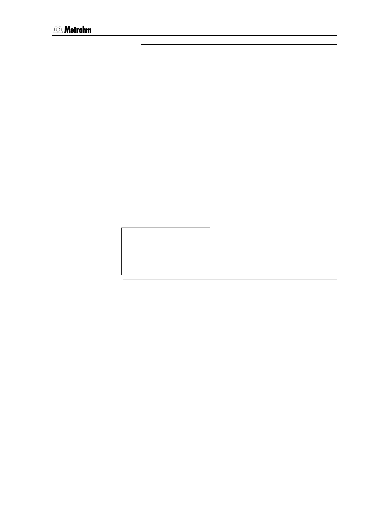
6 Methods / Parameters
780/781 pH/Ion Meter, Manual
<MODE>
PARAMETER Conc
└ activate pulse
auto dos
increment 1...n 1.0E-30...0.1...999.9 mL
The particular volume increment must be entered for each addition of the standard or sample solution.
auto
delta U 1...10...999 mV
During an addition you can terminate the run prematurely with it
be used for the calculation of the result. This manual termination will be
marked in the report.
6.6.2 Preselections
:
└ preselections
├ req.ident
├ req.smpl.size
req.ident: Id1, Id1 & Id2, OFF
For sample identification you can document each measured value with
two Ids in the report header. These can either be predefined under
CONFIG/Report and included in each report or, depending on the Pre-
selections setting, they can be requested before each measurement.
Under
auto the required potential difference must be entered.
Please note that the Dosimat Plus must be properly prepared before the start of an addition run (cylinder freshly filled, air bubbles
removed, etc.).
; only the additions which have already been measured will
Please note that sample identifications requested as a preselection before the measurement will also be stored as an entry under
FIG/Report
. This means that they are again available for the next
CON-
measurement.
req.smpl.size : value, unit, all, OFF
The sample size and sample size unit parameters described under the
calculation parameters (see Section 6.5.4) can also be requested before each measurement. This allows a more individual input of the
sample data.
83
Page 94

6.6 Standard and sample addition (781 only: Conc mode)
780/781 pH/Ion Meter, Manual
84
Page 95
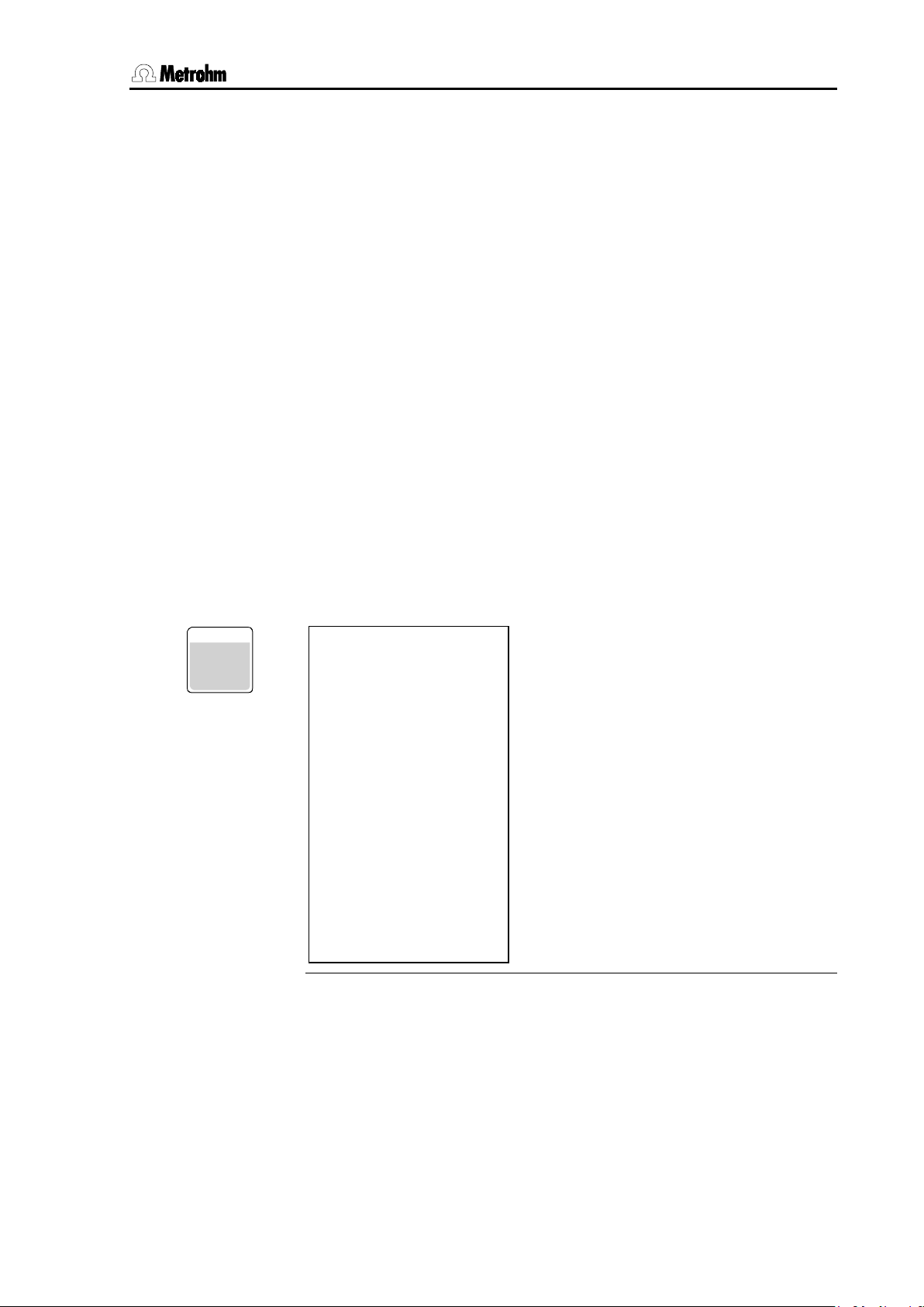
7 Various functions
780/781 pH/Ion Meter, Manual
CAL.DATA
CAL.DATA
ADD.DATA
CAL. DA T A
└ curve
7 Various functions
This section describes various functions of the pH/Ion Meter which cannot be assigned to individual modes.
7.1 Calibration and addition/subtraction data
The current pH calibration data can be called up at any time with the
<
concentration calibration (<
tion data (<
A detailed description of the evaluation of the calibration and addition/subtraction measurements for the calculation of this data can be
found in Section 9.2.
An overview appears which, depending on the measuring mode and
calibration data, can have a different composition.
For example, if no calibration has yet been carried out for a new elec-
trode Id then only the theoretical calibration data slope = 100.00% and
pH(0) = 7.000 will be shown and taken into account for the measurement.
> key. For the 781 pH/Ion Meter the same applies to the
>) in the Conc mode.
>) and the addition or subtrac-
7.1.1 pH calibration data
CAL.DATA
7
├ electr.id
├ method
├ slope
├ pH(0)
├ temperature
├ temp.sensor
├ c.dat.
├ cal.interval
├ variance
├ buffer type
├ no.of buffers
├ cal.table
├ b1
├ b2
:
├ bn
electr.id
If an electrode Id has been selected or entered under PARAMETER pH/
measuring parameters/electr.id
be shown here. The calibration data apply only to this electrode and will
change when a new electrode Id is set under the above measuring parameters (see Section 6.2.2).
before the calibration then it will
85
Page 96

7.1 Calibration and addition/subtraction data
780/781 pH/Ion Meter, Manual
method
The calibration parameters set under PARAMETER pH/calibration
parameters
form part of the method parameters. The corresponding
method name will be shown here if the calibration data has been obtained with this method and the resulting quantities
slope and pH(0)
have not been altered since. If no method name has been issued before the calibration (see Section 6.1) then '
********' will appear here.
slope
The slope of the linear calibration curve obtained during the calibration
will be shown here as a percentage. This is a relative quantity which is
based on the temperature-specific value of the Nernst constant (e.g.
59.16 mV at 25 °C). Without a calibration, or after a single buffer calibration, this is set to 100 %.
This value can be altered manually for test purposes. However, afterwards the information about the method will be missing from the list
and from the calibration data report. The calibration date and time will
be updated and the temperature information and the calibration table
(see below) will be removed. In addition this action will be documented
by the entry '
manual' under CAL.DATA/variance.
pH(0)
This is the second characteristic quantity of the calibration curve. pH(0)
is the pH value at 0 mV. It can also be altered manually for test purposes. The other entries under
CAL.DATA will be altered in the same way as
for a manual alteration of the slope (see above).
temperature
The calibration temperature is shown here.
temp.sensor
If the calibration temperature has been determined automatically by a
connected temperature sensor then its type will be shown here
Pt1000' or 'NTC'). A manually entered temperature for the calibration
('
will be indicated accordingly ('
manual').
c.dat.
The date and time of the calibration is shown here.
cal.interval
If a calibration interval has been defined under PARAMETERS pH/ cal-
ibration parameters/cal.interval
can be used together with the calibration time given under
then it will be shown here. It
c.dat. to
estimate the time that the next calibration is due.
86
Page 97

7 Various functions
780/781 pH/Ion Meter, Manual
QUIT
SELECT
variance
If at least 3 calibration buffers have been used then the calibration function will be calculated as a compensation curve according to the principle of the smallest mean-square error (linear regression). The resulting
variance will be given here. A more detailed explanation of these calculations is given in Section 9.2.1.
Each subsequent manual alteration of the calibration data pH(0) and
slope will be documented by the entry '
manual' against these parame-
ters.
buffer type
The type of buffer defined in the calibration parameters at the time
when calibration was carried out is shown here.
no.of buffers
The number of buffers actually measured is shown here. This can be
lower than that given in the calibration parameters, as a calibration can
be terminated prematurely with <
>; only the buffers which have
already been measured will then be used for the calculation of the calibration data.
cal.table: original, delete n, reset cal
This entry can be used to delete individual buffers from the calibration
table ('
('
delete n') or to delete all the calibration data of an electrode Id
reset cal').
original
If you use <
buffer data previously deleted with '
> to chose the option 'original' then all the
delete n' will be reinserted in
the calibration table and used for calculating the calibration data.
delete n
From a calibration list containing at least 3 buffer entries you can
remove individual buffer data by selecting '
delete n' and enter-
ing the number of the buffer to be deleted in the following line:
delete n: 1..9
The deleted buffer will then be indicated in the calibration table by
deleted'. The measuring points of deleted buffers are also indi-
'
cated in the graphical display by an 'o' instead of a '+'.
You can reinsert all deleted buffers in the calibration table with the
option '
original'.
87
Page 98

7.1 Calibration and addition/subtraction data
780/781 pH/Ion Meter, Manual
QUIT
reset cal
With this option you can reject all the calibration data of an electrode Id. They are then in the same state as before the first calibration (slope = 100%, pH(0) = 7).
Although the electrode Id is retained, it cannot be selected under
PARAMETER pH/measuring parameters/electr.id until it
has been calibrated again.
b1, b2...bn
For each calibration buffer the pH value used and the measured potential are given. The given value for the pH is taken from the stored series
of buffers of the buffer type selected in the calibration parameters (see
Section 9.4). The pH values for temperatures within the given 5 °C steps
are calculated by linear interpolation.
A buffer which has been deleted by
here by '
deleted'.
cal.table: delete n is shown
curve < –> >
If at least 2 calibration buffers have been used then the calibration
curve will be shown as a graph here. The graphics display is accessed
with <
>:
This display is exited with <
>.
88
Page 99
7 Various functions
780/781 pH/Ion Meter, Manual
CAL. DA T A
7
7.1.2 Conc calibration data (781 pH/Ion Meter only)
CAL.DATA
├ ion type
├ electr.Id
├ method
├ slope
├ E(0)
├ c(blank)
├ temperature
├ temp.sensor
├ c.dat.
├ cal.interval
├ variance
├ no.of standards
├ cal.table
├ st1
├ st2
:
├ stn
└ curve
ion type
The analyte ion which has been defined during the calibration under
PARAMETER Conc/ion parameters is shown here. As with the follow-
ing electrode Id, the current calibration data changes as the ion parameter changes.
electr.id
If an electrode Id has been entered or selected before the calibration
under
PARAMETERS Conc/measuring parameters/electr.id then it
will be shown here. Electrode Ids can be defined for a particular type of
ion. The calibration data will apply to this electrode only and will change
when a new electrode Id is set under the above measuring parameters
(see Section 6.5.5).
method
The calibration parameters set under PARAMETER Conc/calibration
parameters
form part of the method parameters. The appropriate
method name will be shown here when the calibration data have been
determined using this method and the resulting quantities
c(blank) have not been altered since. If no method name has
and
been assigned before the calibration (see Section 6.1), then '
slope, E(0)
********'
will appear here.
slope
The slope of the calibration function obtained during the calibration will
be shown here in mV. With no calibration this will be set to the theoretical value of +59.2 mV or -59.2 mV per ion charge at 25 °C.
This value can be altered manually for test purposes. However, afterwards the information about the method will be missing from the list
89
Page 100

7.1 Calibration and addition/subtraction data
780/781 pH/Ion Meter, Manual
and from the calibration data report. The calibration date and time will
be updated and the temperature information and the calibration table
(see below) will be removed. In addition this action will be documented
by the entry '
manual' under CAL.DATA/variance.
E(0)
This is the second characteristic quantity of the calibration function.
E(0) is the potential at log(c) = 0, i.e. the U-axis intercept of the calibration function in the U/log c plot. A more detailed explanation of the calculation of the calibration data is given in Section 9.2.2.
E(0) can also be altered manually for test purposes. The other entries
under
CAL.DATA will then be altered in the same way as for a manual
alteration of the slope (see above).
c(blank)
This is the third characteristic quantity of the concentration calibration
function. To a certain extent it reflects the curvature of the otherwise linear calibration function at the lowest concentrations. It is only calculated
when at least three standards have been measured (see also Sec-
tion 9.2.2). If the value for c(blank) is sufficiently small, i.e. if the influence of this quantity on the later result can no longer be measured,
then it will be set as zero. Instead the variance will then be calculated
even when only three standards have been measured (see below).
c(blank) can also be altered manually for test purposes. The other entries under
CAL.DATA will then be altered in the same way as for a
manual alteration of the slope (see above).
temperature
The calibration temperature is shown here.
temp.sensor
If the calibration temperature has been determined automatically by a
connected temperature sensor then its type will be shown here
Pt1000' or 'NTC'). A manually entered temperature for the calibration
('
will be indicated accordingly ('
manual').
c.dat.
The date and time of the calibration will be shown here.
cal.interval
If a calibration interval has been defined under PARAMETER Conc/
Calibration parameters/cal.interval
It can be used together with the calibration time given under
then it will be shown here.
c.dat. to
estimate the time that the next calibration is due.
90
 Loading...