

Page 1

CH-9101 Herisau/Switzerland
E-Mail info@metrohm.com
Internet www.metrohm.com
775 Dosimat
Instructions for Use
8.775.1013
2005.06 ti/dm
Page 2

Page 3

Content
Content
1 Overview ...................................................................................................................2
2 Error messages, troubleshooting............................................................................4
2.1 Special messages and error messages ..................................................................... 4
2.2 Diagnosis ................................................................................................................... 5
2.3 RAM initialisation......................................................................................................... 8
2.4 Releasing a locked spindle with insertd Exchange Unit.............................................9
3 Appendix.................................................................................................................10
3.1 Technical specifications............................................................................................ 10
3.2 Warranty and certificates .......................................................................................... 12
3.2.1 Warranty ............................................................................................................. 12
3.2.2 Certificate of Conformity and System Validation................................................ 13
3.3 Scope of delivery and ordering designations ........................................................... 15
Index...........................................................................................................................16
775 Dosimat
Page 4

Page 5
Overview
Explanation of symbols:
< > means "key", e.g. <GO> means key "GO"
DOS.....0.000 ml means "display"
775 Dosimat
1
Page 6
Overview
1 Overview
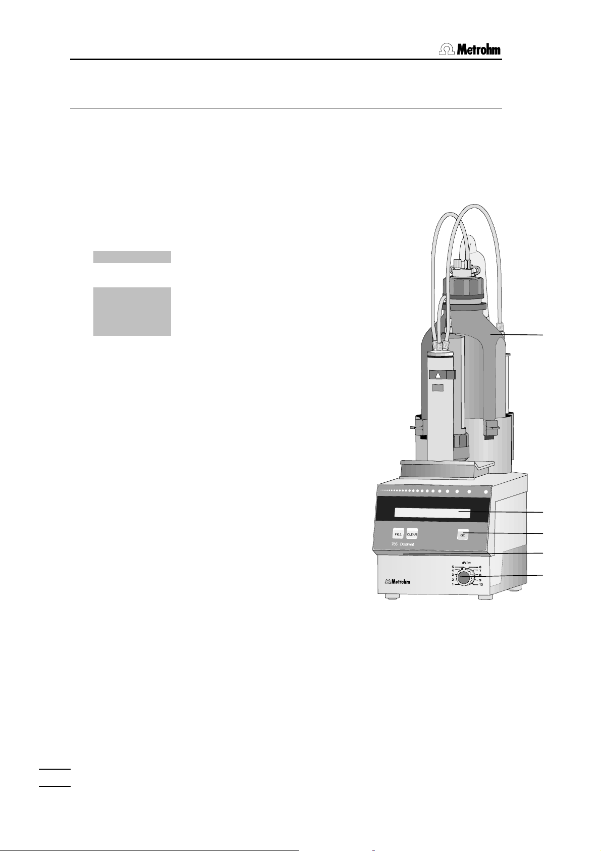
Front view of instrument:
1 Exchange unit
Choose the volume of the Exchange unit in such a
way that a volume between 10...100% of the nominal
volume is expelled.
2 Display
The 16 digit display shows all important information:
DOS 3.456 ml Mode (DOS = dosing) and dosed
DOS ↑ 3.456 ml The piston is moving upwards.
DOS ↓ 3.456 ml The piston is moving downwards.
DOS → 3.456 ml The cock is turned to the right.
DOS ← 3.456 ml The cock is turned to the left.
The display of the status
important for very slow dosings where movements of
the piston cannot be clearly identified.
3 Operating keys at the Dosimat
<FILL> Filling of the dosing cylinder.
<CLEAR> Resetting of the volume display to 0.
<GO> Dosing goes on as long as <GO> is
pressed.
4 Setting of display contrast
5 Analogue setting of dosing rate
Position 1 = lowest rate
Position 10 = highest rate
volume. Dosimat is in stand-by
position
↑ resp.↓ are specially
1
2
3
4
5
775 Dosimat
2
Page 7

Overview
Rear view of instrument:
6 Identification plate
Indication of model, series and serial number.
7 Indication of power voltage
Make sure the current has been adapted correctly
before Dosimat is switched on.
8 Connection for external dosing contact
E.g. 6.2107.000 push button cable.
9 Power connection
In power supply systems, in which strong HF
interferences (transients) are superimposed on the
power voltage, the 775 Dosimat should be
connected via an additional power line filter, e.g.
METROHM 615 model.
The main cables supplied with the instrument are
three-core and equipped with a plug with an earthing
pin. If a different plug has to be fitted, the
yellow/green lead must be connected to the
protective earth. Each break in the earthing inside or
outside the instrument can make it a hazard.
When the instrument is opened or if parts of it are
removed, certain components may be live if the
instrument is connected to the power line. The power
cable must therefore always be unplugged when
certain adjustments are made or parts replaced.
10 Earthing socket
The 775 Dosimat must be grounded correctly and
effectively, if necessary through the separate
earthing socket.
11 Connection for stirrer
In general a Magnetic Stirrer (forms a complete
titrating stand). Other stirrers may be connected as
well, e.g. a METROHM Rod Stirrer. Supply voltage
output: +9 V DC (I ≤ 200 mA).
12 Power switch
Switching on and off Dosimat.
Made by Metrohm
Herisau Switzerland
1.775.
Nr.
230/240 V
220 V
117 V
100 V
f = 50-60 Hz
S = 15 VA
E
on
off
D
11 7612 10 98
775 Dosimat
3
Page 8

2.1. Special messages and error messages
2 Error messages, troubleshooting
2.1 Special messages and error messages
error 1 Check sum error in PROM.
Remedy: Call Metrohm-Service.
error 2 RAM-check: Error in on-chip-RAM.
Remedy: Call Metrohm-Service.
error 3 RAM-check: Error in off-chip-RAM.
Remedy: Call Metrohm-Service.
error 4 RAM-check: Error in on- and off-Chip-RAM.
Remedy: Call Metrohm-Service.
error 5 Check sum error in off-chip-RAM.
Remedy: RAM has to be re-initialized: Switch Dosimat off.
Press <FILL> during switching it on again. Display shows
"RAM init.". Press <GO>. Display shows "RAM init. passed".
<CLEAR> leads to basic program.
no exch. unit! Exchange unit is not (properly) mounted.
Exit: Mount Exchange unit properly.
775 Dosimat
4
Page 9

2.2 Diagnosis
2.2 Diagnosis
2.2.1 General
The 775 Dosimat is a very precise and dependable feeding instrument.
Thanks to its rugged construction, it is highly unlikely that external mechanical or electrical influences will have any adverse effect on its functions.
Although a fault in the instrument can not be excluded with certainty, the
possibility is greater that malfunctions are caused by wrong operation or
handling, through improper connections and the operation with third-party
devices.
Whatever the case, it is always advisable to localise the fault with the diagnostic tests, which can be performed quickly and simply. The customer
need call Metrohm service only when the instrument really has a fault. Further, he can use the results of the specific diagnostic function to provide the
service engineer with much more precise information.
In the case of inquiries, always quote the serial number on model plate (see
page 3) and if applicable the error message.
Procedure
The diagnostic menu listed in section 2.2.2 shows all components for which
detailed instructions (diagnostic steps) are available for checking the functionality.
In the case of a possible malfunction, we advise you to perform either the
corresponding diagnostic step or all diagnostic steps as a routine check on
the instrument.
The reactions of the Dosimat to the instructions must be compared with the
descriptions in the diagnostic step. If the Dosimat do not show the expected reaction ("No" case), the appropriate diagnostic step must be repeated to exclude operating errors. However, it is highly probable that repeated wrong reactions indicate a malfunction.
Equipment required:
3.496.0070 Dummy-exchange unit (or exchange units if possible with different cylinder
6.2107.000 Push-button cable or ordinary test lead with 4 mm banana plugs
-.---.---- Stop watch or watch with second hand.
volumes).
775 Dosimat
5
Page 10

2.2. Diagnosis
2.2.2 Summary
2.2.3 RAM-test ............................................................................6
2.2.4 Diagnosis of spindle zero and cock changeover..............6
2.2.5 Diagnosis of spindle drive .................................................7
2.2.3 RAM-test
1.
Power off.
2.
Remove exchange unit.
3.
Disconnect all cables at rear, except mains cable.
4.
Power on and simultaneously press key <CLEAR> and keep pressed until
5.
6.
RAM test
<GO>
The processor now checks the RAM of the Dosimat, without affecting the content. The exclamation (!) appears when the test is positive. The test can be continued at will. If no fault is found, the following appears:
RAM test ! (exclamation mark is flashing)
The test is broken off with <CLEAR> (Depress the key only until the dotted pattern appears)
no exch. unit!
2.2.4 Diagnosis of spindle zero and cock changeover
1.
Power off.
2.
Insert exchange unit.
3.
Power on.
4.
5.
Dosimat fills.
Remove exchange unit.
To check the spindle zero.
The spindle must be 0.2 - 0.6 mm below the edge of the mounting plate (see Fig. 1).
The link piece of the cock coupling must be parallel to the side walls of the Dosimat (see Fig. 2).
Fig. 1 Fig. 2
0.2 - 0.6 mm
775 Dosimat
6
Page 11

2.2 Diagnosis
2.2.5 Diagnosis of spindle drive
1.
Insert exchange unit and put the burette tip into a collecting receptacle.
2.
Connect push-button cable 6.2107.000 (if available).
3.
Knob 'dV/dt' fully to the right.
4.
Press feed button 6.2107.000 (if not available, <GO>) all the time until the piston
rod reaches the top position and simultaneously measure the time from start to
stop.
5.
The running time of the spindle is 18 ... 22 s.
General rules:
• Dosimat fills automatically.
• Spindle and cock must move in regular speed (observe sound!)
• In the filling position the cock coupling must turn the lever of the exchange unit blamelessly to the
left stop (almost without play and without jamming).
Repeat point 4. and now measure the filling time until the spindle stops at the
lower end.
The running time (filling time) of the spindle is 18 ... 22 s.
6.
Knob 'dV/dt' fully to the left.
7.
<CLEAR>
8.
DOS 0.000 ml
Press feed button 6.2107.000 (if not available, <GO>) all the time and simultaneously measure the time, until, depending on the exchange unit, the volume in the
table below is reached.
1 ml: 0.02 ml
5 ml: 0.1 ml
10 ml: 0.2 ml
20 ml: 0.4 ml
50 ml: 1 ml
9.
The time must be 14 ... 24 s.
<FILL>
DOS 0.000 ml
775 Dosimat
7
Page 12

2.3. RAM-initialisation
2.3 RAM-initialisation
In rare cases, it is possible that major interference signals such as line spikes and lightning can have an adverse influence on the contents of the data memory. If the contents
of the data memory are undefined, this is indicated after “power on“ with ‘error 5'. The
keyboard is then blocked, no entering is possible until the RAM is initialised again.
1.
Disconnect all cables at rear, except mains cable.
2.
Power off and wait 5 s.
3.
Power on and simultaneously press key <FILL> and keep pressed until
4.
5.
RAM init.
<GO>
RAM init. passed
<CLEAR>
DOS 0.000 ml
Dosimat fills.
The RAM-initialisation overwrites the data present in the User-Memory with the standard data.
775 Dosimat
8
Page 13

2.4 Releasing a locked spindle
2.4 Releasing a locked spindle
with inserted Exchange Unit
The burette drive may very occasionally jam at the top or bottom end of the cylinder. If
jamming occurs at the top or when the drive is out of function, the Exchange Unit can no
longer removed. In this case, it is necessary to proceed as follows:
2 screws (M4 countersunk)
Fig. 3
1.
Disconnect instrument from power supply!
2 screws (M3 fillister head)
knob
edge of bench
2.
Remove control knob.
3.
Place instrument over edge of bench to allow the M3 screws to be removed.
4.
Remove M4 screws.
5.
Lift off top part of instrument together with Exchange Unit in the manner shown by
the arrow.
The electronic circuits are now accessible!
On no account touch these!
6.
Remove spindle from mechanical stop by turning the large gear wheel. (In case
that the motor is inoperative, position spindle by hand to zero position.)
775 Dosimat
9
Page 14

3.1. Technical specifications
3 Appendix
3.1 Technical specifications
Exchange units 1, 5, 10, 20, 50 mL burette cylinder volumes,
preferably with flat cock for automatic cock changeover
Resolution 10'000 pulses per 100% of burette volume
Exactitude Metrohm dosimats and exchange units meet the requirements
of ISO/EN/DIN Standard 8655-3 "Piston-operated volumetric
apparatus – Part 3: Piston burets" and DIN Standard 12 650.
Limits according to ISO/EN/DIN 8655-3
Cylinder
volume
1 mL ± 0.6% ± 6 µL ± 0.1% ± 1 µL
5 mL ± 0.3% ± 15 µL ± 0.1% ± 5 µL
10 mL ± 0.3% ± 20 µL ± 0.07% ± 7 µL
20 mL ± 0.2% ± 40 µL ± 0.07% ± 14 µL
50 mL ± 0.2% ± 100 µL ± 0.05% ± 25 µL
Dispensing time for 100% of burette cylinder volume
20 s ... app. 17 min
Display LCD, 16 characters
Material
Cabinet Polybutylene terephthalate (PBTP)
Key cover Polycarbonate (PC)
Ambient temperature Nominal functional range +5... +40°C
Safety specifications Designed and tested in accordance to IEC-Publication 1010,
Max. permissible system. error
Metrohm agencies throughout the world offer you the possibility of checking the accuracy of your exchange units and Dosimats locally and also of certifying them. If the dosing cylinder
and/or piston of an exchange unit are replaced then we recommend that an accuracy check is carried out.
Size of characters: 4.84 x 8.01 mm
Storage, transport - 40... +60°C
safety class I. This manual contains some information and
warnings which have to be followed by the user to ensure safe
operation and to retain apparatus in safe condition.
Max. permissible random error
775 Dosimat
10
Page 15

3.1 Technical specifications
Power supply
Voltage 100, 117, 220, 230/240 V ± 10% (adjustable)
Frequency 50... 60 Hz
Consumption 15 VA
Fuse Thermal fuse (100°C)
Dimensions
Dosimat with Exchange unit
Width 150 mm
Height 450 mm
Depth 275 mm
Weight
Dosimat app. 2,9 kg
775 Dosimat
11
Page 16

3.2. Warranty and certificates
3.2 Warranty and certificates
3.2.1 Warranty
The warranty regarding our products is limited to rectification free of
charge in our workshops of defects that can be proved to be due to
material, design or manufacturing faults which appear within 12
months from the day of delivery. Transport costs are chargeable to
the purchaser.
For day and night operation, the warranty is valid for 6 months.
Glass breakage in the case of electrodes or other glass parts is not
covered by the warranty. Checks which are not a result of material or
manufacturing faults are also charged during the warranty period.
For parts of outside manufacture insofar as these constitute an appreciable part of our instrument, the warranty stipulations of the
manufacturer in question apply.
With regard to the guarantee of accuracy, the technical specifications in the Instructions for Use are authoritative.
Concerning defects in material, construction or design as well as the
absence of guaranteed features, the purchaser has no rights or
claims except those mentioned above.
If damage of the packaging is evident on receipt of a consignment
or if the goods show signs of transport damage after unpacking, the
carrier must be informed immediately and a written damage report
demanded. Lack of an official damage report releases METROHM
from any liability to pay compensation.
If any instruments and parts have to be returned, the original packaging should be used if at all possible. This applies above all to instruments, electrodes, burette cylinders and PTFE pistons. Before
embedding in wood shavings or similar material, the parts must be
packed in a dustproof package (for instruments, use of a plastic bag
is imperative). If open assemblies are enclosed in the scope of delivery that are sensitive to electromagnetic voltages (e.g. data interfaces etc.) these must be returned in the associated original protective packaging (e.g. conductive protective bag). (Exception: assemblies with built-in voltage source belong in a non-conductive protective packaging). For damage which arises as a result of noncompliance with these instructions, no warranty responsibility whatsoever will be accepted by METROHM.
775 Dosimat
12
Page 17

3.2 Warranty and certificates
3.2.2 Certificate of Conformity and System Validation
This is to certify the conformity to the standard specifications for electrical appliances and
accessories, as well as to the standard specifications for security and to system validation
issued by the manufacturing company.
Name of commodity: 775 Dosimat
System software: Stored in ROMs
Name of manufacturer: Metrohm Ltd., Herisau, Switzerland
This Metrohm instrument has been built and has undergone final type testing according
to the standards:
Electromagnetic compatibility: Emission
EN50081-1/92, EN55022/class B,
EN55011/class B Generic emission
Electromagnetic compatibility: Immunity
EN50082-1/92 Immunity
IEC1000-4-2/95 (level 4), NAMUR/93 Static discharge
IEC801-3, ENV50140/93+ENV50204/93 (level 2) Radiated rf electromag.field immunity
IEC801-4, IEC1000-4-4/95 (level 3) El.fast transient requirements
IEC801-5, IEC1000-4-5/95 (level 2/3) "Surges" immunity
NAMUR/93 Paragr. 3.2.2., IEC1000-4-11/94 Voltage dips, short interruptions
Security specifications
IEC1010 class1, EN61010 class1, UL3101-1, EN60947:IP31
The technical specifications are documented in the instruction manual.
The system software, stored in Read Only Memories (ROMs) has been validated in connection with standard operating procedures in respect to functionality and performance.
The features of the system software are documented in the instruction manual.
Metrohm Ltd. is holder of the SQS certificate of the quality system ISO 9001 for quality
assurance in design/development, production, installation and servicing.
Herisau, May 14, 1998
Dr. J. Frank Ch. Buchmann
Development Manager Production and
Quality Assurance Manager
775 Dosimat
13
Page 18

3.2. Warranty and certificates
Ionenanalytik • Analyse des ions • Ion analysis • Análisis iónico
775 Dosimat
EU- Declaration of Conformity
The company Metrohm AG, Herisau, Switzerland, certifies herewith, that the following
instrument:
775 Dosimat
meets the CE mark requirements of EU Directives 89/336/EWG and 73/23/EWG.
Source of specifications:
EN 50081-1 Electromagnetic compatibility, basic specification Emitted Interference
EN 50082-1 Electromagnetic compatibility, basic specification Interference Immunity
EN 61010 Safety requirements for electrical laboratory measurement and control
equipment
Description of apparatus:
Dispensing unit for titrating and dosing tasks.
Herisau, May 20, 1998
Dr. J. Frank Ch. Buchmann
Development Manager Production and
Quality Assurance Manager
775 Dosimat
14
Page 19

3.3 Scope of delivery and ordering designations
3.3 Scope of delivery and ordering designations
Dosimat 775 ......................................................................................2.775.0010
including the following accessories:
1 Push button cable ............................................................................................ 6.2107.000
1 Key for Exchange units......................................................................................6.2739.010
1 Exchange Unit with 20 mL glass cylinder ...................................................... 6.3026.220
1 Power cable with cable socket, type CEE(22), V
Cable plug to customer's specifications
type SEV 12 (Schweiz...).................................................................................. 6.2122.020
type CEE(7), VII (Deutschland...) ..................................................................... 6.2122.040
type NEMA/ASA (USA...) ................................................................................. 6.2122.070
1 Instructions for Use for Dosimat 775................................................................. 8.775.1013
Options
Accessories to separate order and on payment of extra charge:
806 Exchange Unit 6.3026.xxx
Buret unit for Metrohm Dosimats, Titrinos, Titrandos; with glass cylinder, PCTFE/PTFE flat
cock and built-in data chip
806 Exchange Unit with 1 mL glass cylinder........................................................ 6.3026.110
806 Exchange Unit with 5 mL glass cylinder........................................................ 6.3026.150
806 Exchange Unit with 10 mL glass cylinder...................................................... 6.3026.210
806 Exchange Unit with 20 mL glass cylinder...................................................... 6.3026.220
806 Exchange Unit with 50 mL glass cylinder...................................................... 6.3026.250
Ceramic flat cock.................................................................................................. 6.1542.010
Stirrer and working equipment
728 Magnetic stirrer.............................................................................................. 2.728.0040
Magnetic stirring bars, length
12 mm........................................................................................................... 6.1903.010
16 mm........................................................................................................... 6.1903.020
25 mm........................................................................................................... 6.1903.030
802 Rod stirrer ...................................................................................................... 2.802.0010
Electrode holder ................................................................................................. 6.2021.020
775 Dosimat
15
Page 20

Index
Index
Keys are marked with < >, display texts are in bold characters.
A
Accessories........................................15
Arrows ..................................................2
C
CE sign............................................... 14
Certificate ...........................................13
<CLEAR>............................................ 2
Connection
Power .............................................3
Stirrer ...............................................3
D
Delivery............................................... 15
Diagnose............................................ 5ff
Dosing.................................................. 2
Dosing key ...........................................3
Dosing rate...........................................2
E
Earthing ................................................ 3
error X ................................... 4
Error messages.................................... 4
Exchange unit..................................... 15
Expelling rate........................................ 2
F
<FILL> ................................................2
Filling rate.............................................2
G
<GO>.................................................. 2
I
Initializing.............................................. 8
ISO quality system .............................13
N
no exch.unit! ................................... 4
O
Ordering designations ....................... 15
P
Power
Connection ..................................... 3
Switch .............................................3
Voltage ............................................ 3
R
RAM-Initializing .................................... 8
Rate...................................................... 6
S
Scope of delivery ............................... 15
Stirrer connection................................. 3
Stirrer ................................................. 15
T
Technical specifications .................... 10
W
Warranty............................................. 12
775 Dosimat
16
 Loading...