

Page 1

CH-9101 Herisau/Switzerland
Tel. +41 71 353 85 85
Fax +41 71 353 89 01
E-Mail sales@metrohm.ch
Internet http://www.metrohm.ch
774 Oven Sample Processor
Instructions for use
Program version 5.774.0010
8.774.1043
2005.07 dm
Page 2

Page 3

Table of contents
Page
1 Overview 1
1.1 Application range___________________________________________ 1
1.2 Application possibilities_____________________________________ 1
1.3 Instrument description ______________________________________ 3
1.3.1 Oblique view from the right-hand side ......................................... 3
1.3.2 Oblique view from left-hand side.................................................. 4
1.3.3 Rear view....................................................................................... 5
1.3.4 The socket strip (rear panel):........................................................ 5
1.3.5 Guide head ................................................................................... 6
1.3.6 Sample rack.................................................................................. 6
1.3.7 Sample vials.................................................................................. 7
2 Installation 8
2.1 Setting up the instrument____________________________________ 8
2.2 Power supply ______________________________________________ 8
2.3 Safety considerations ______________________________________ 10
2.4 Arranging the accessories__________________________________ 11
2.4.1 Connecting the keyboard ........................................................... 11
2.4.2 Equipping the guide head ..........................................................12
2.4.3 Adjusting the sample rack .......................................................... 12
2.4.4 Adjusting the needle position .....................................................13
2.4.5 Installation of the tubing system and the drying flask................ 14
2.4.6 Installation of the measuring cell ................................................ 15
2.5 Integration ________________________________________________ 15
2.5.1 Remote connections................................................................... 16
2.5.2 External bus connections ...........................................................19
2.5.3 Serial connection (RS232) .......................................................... 20
2.5.4 Connecting a printer ................................................................... 21
3 Introduction 23
3.1 Configuration _____________________________________________ 23
3.1.1 Basic settings ............................................................................. 23
3.1.2 Oven settings.............................................................................. 24
3.1.3 Rack definitions .......................................................................... 25
3.1.4 Dosing units ................................................................................ 26
3.1.5 RS232 interface........................................................................... 27
3.1.6 Lock keyboard functions ............................................................28
3.2 Manual operation __________________________________________ 30
3.3 Methods and Sequences ___________________________________ 33
3.3.1 Designing a method ................................................................... 33
3.3.2 LEARN mode and TRACE function ............................................ 34
3.3.3 Process control........................................................................... 35
3.3.4 POWER-UP methods.................................................................. 36
4 Oven control and gas flow 37
4.1 Oven control ______________________________________________ 37
4.2 Gas flow __________________________________________________ 38
4.3 KF Moisture determination _________________________________ 40
Page 4

Table of contents
5 Detailed description 43
5.1 The display ________________________________________________43
5.2 The keyboard ______________________________________________44
5.3 Menu organization _________________________________________62
5.4 Command reference________________________________________76
5.5 Printing reports ____________________________________________ 85
5.6 Sample racks ______________________________________________89
5.7 Dosimats and Dosinos______________________________________92
5.8 Remote Interface ___________________________________________97
5.9 Operation via RS232 Interface______________________________101
5.10 The remote control tree ___________________________________106
5.11 Description of the remote control commands _______________116
5.12 Properties of the RS232 Interface __________________________131
Page
5.2.1 Individual key functions .............................................................. 45
5.2.2 Data entry ................................................................................... 59
5.2.3 Text Entry .................................................................................... 60
5.3.1 Configuration .............................................................................. 63
5.3.2 Parameters ................................................................................. 68
5.3.3 User Defined Methods ............................................................... 75
5.5.1 Automatic reports ....................................................................... 88
5.5.2 Manual reports............................................................................ 88
5.9.1 General rules ............................................................................ 101
5.9.2 Calling up Objects ................................................................... 102
5.9.3 Triggers..................................................................................... 103
5.9.4 Status and Error Messages...................................................... 103
5.9.5 Error Messages, Errors............................................................. 104
5.10.1 Overview ................................................................................. 106
5.10.2 &Mode .................................................................................... 106
5.10.3 &Config................................................................................... 108
5.10.4 &Info ....................................................................................... 109
5.10.5 &Setup .................................................................................... 112
5.10.6 &UserMeth.............................................................................. 113
5.10.7 &Assembly.............................................................................. 113
5.10.8 &Diagnose.............................................................................. 115
5.11.1 &Mode … ............................................................................... 116
5.11.2 &Config … .............................................................................. 119
5.11.3 &Info …................................................................................... 122
5.11.4 &Setup … ............................................................................... 125
5.11.5 &UserMeth …......................................................................... 127
5.11.6 &Assembly …......................................................................... 128
5.11.7 &Diagnosis … ........................................................................ 130
5.12.1 Data Transfer Protocol ........................................................... 131
5.12.2 Handshake ............................................................................. 131
5.12.3 Pin Assignment....................................................................... 135
5.12.4 What to do if Data Transfer fails? ........................................... 136
Page 5

Table of contents
Page
6 Appendix 137
6.1 Error messages __________________________________________ 137
6.2 Technical data____________________________________________ 140
6.3 Maintenance and servicing ________________________________ 142
6.3.1 Maintenance / service............................................................... 142
6.3.2 Servicing / care ......................................................................... 142
6.4 Diagnosis ________________________________________________ 143
6.4.1 General ..................................................................................... 143
6.4.2 Preparing the instrument ..........................................................144
6.4.3 Main memory (RAM)................................................................. 145
6.4.4 Display ......................................................................................145
6.4.5 Keypad...................................................................................... 146
6.4.6 Remote interface....................................................................... 146
6.4.7 RS232 interface......................................................................... 147
6.4.8 External bus interface ...............................................................147
6.4.9 Beeper....................................................................................... 148
6.4.10 Rack code recognition............................................................ 148
6.5 Initialise data memory_____________________________________ 149
6.6 Validation / GLP __________________________________________ 152
6.7 Warranty and Conformity__________________________________ 154
6.7.1 Warranty.................................................................................... 154
6.7.2 EU Declaration of Conformity ................................................... 155
6.7.3 Certificate of Conformity and System Validation...................... 156
6.8 Accessories______________________________________________ 157
7 Index 159
Page 6

Page 7
1.1 Application range
1 Overview
1.1 Application range
The Metrohm 774 Oven Sample Processor is a very versatile instrument. It
has been specially designed for laboratory use and can be used for a wide
range of applications. It provides an essential service when large numbers
of samples have to be processed in which the samples require to be
heated and/or whenever it is necessary to remove moisture or organic solvents from solids or liquids by the application of heat.
The construction of the 774 Oven Sample Processor has been principally
based on the determination of moisture by the oven method. The sample
heated in the oven block releases its moisture as water vapor which is
transferred to a measuring cell in a stream of gas. The moisture determination in the cell can be carried out either coulometrically or volumetrically according to Karl Fischer.
This method is becoming increasingly popular wherever moisture determinations have to be carried out in matrices which interfere with the moisture
determination process or which release their moisture only with great difficulty.
Its comprehensive range of communications possibilities means that it
cannot just work together with the wide range of Metrohm titrators, meters
and dosing instruments via its parallel remote interface and its serial RS232
interface, but that it can also control or be controlled by any instrument
which is equipped with a suitable communications interface. These abilities
mean that it is predestined for automation tasks in a modern laboratory,
even within highly integrated laboratory data systems.
1.2 Application possibilities
Despite its comprehensive range of commands and numerous configuration possibilities the 774 Oven Sample Processor, with its capability of
managing operator-defined methods, offers an uncomplicated operation
system which is suitable for routine use.
The standard methods for routine tasks which we supply together with the
instrument can be used without any further ado. After a short familiarization
period the operators can alter them to suit their own requirements and store
them in the instrument. In this way the 774 Oven Sample Processor can
774 Oven Sample Processor, Instructions for use
1
Page 8

1 Overview
also be used for demanding special applications as well as for routine
tasks.
The operating sequences for processing individual samples can be freely
defined within wide limits. The same applies to the start and final sequences, which always need to be carried out once before the start and
once at the end of a sample series.
A learning mode is provided for the creation of operating sequences; with
its help command parameters can be set manually.
The standard sample rack offers place for 36 sample vials (22 mm x 38
mm). Freely definable "special beaker" positions can also be defined. These
are used for positioning conditioning beakers, which can be selected in
each part-sequence, on the rack.
2
774 Oven Sample Processor, Instructions for use
Page 9
1.3 Instrument description
A
1.3 Instrument description
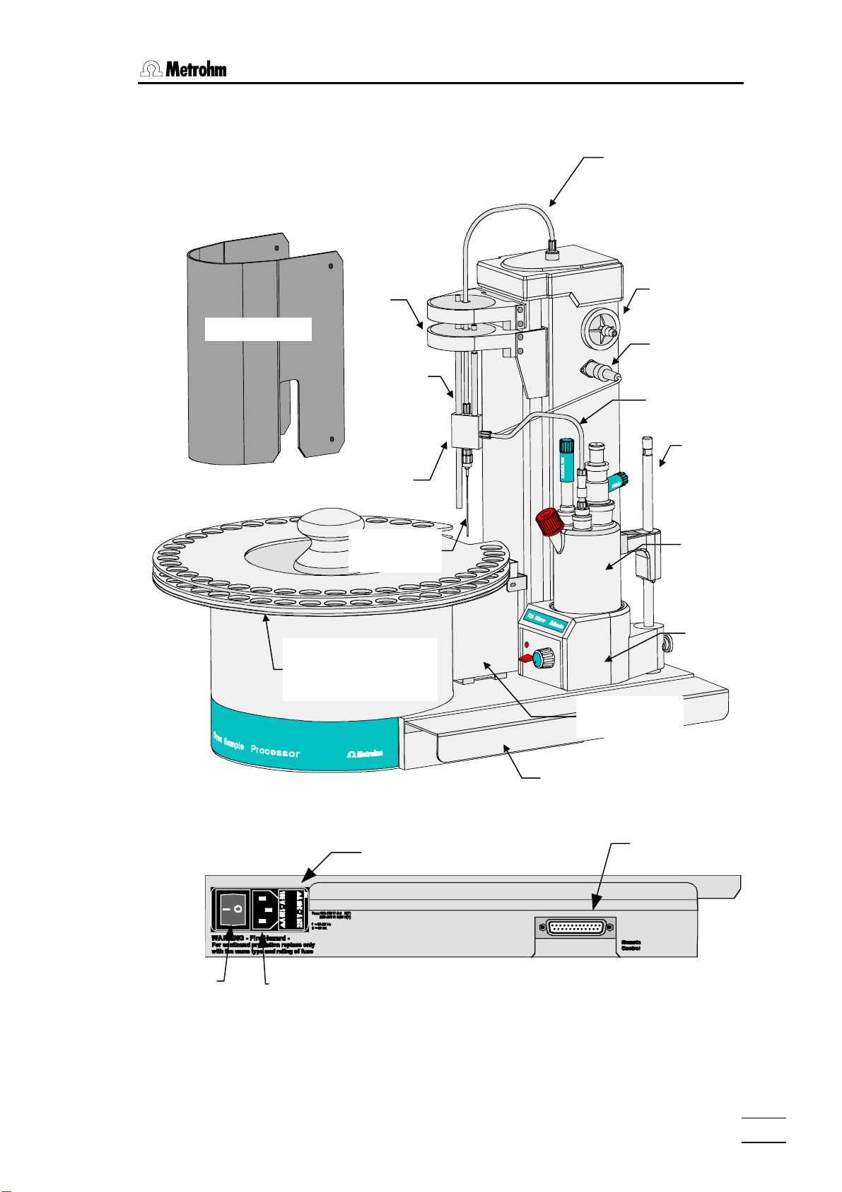
1.3.1 Oblique view from the right-hand side
equipped with Coulometer cell
Gas supply
Protective cover
Sample rack with 36
places (including conditioning position)
Lift
Guide rod
(adjust-
Guide head
Double
hollow needle
ir inlet filter
Connection for
outlet heater
Outlet heater /
transfer hose
Support rod
Coulometer cell
with generatorand indicator
electrode
Magnetic stirrer
The socket strip:
Mains switch
Fuse holder
Mains connection
Oven with
protective jacket
Plug cover
Remote
interface
774 Oven Sample Processor, Instructions for use
3
Page 10
1 Overview
j
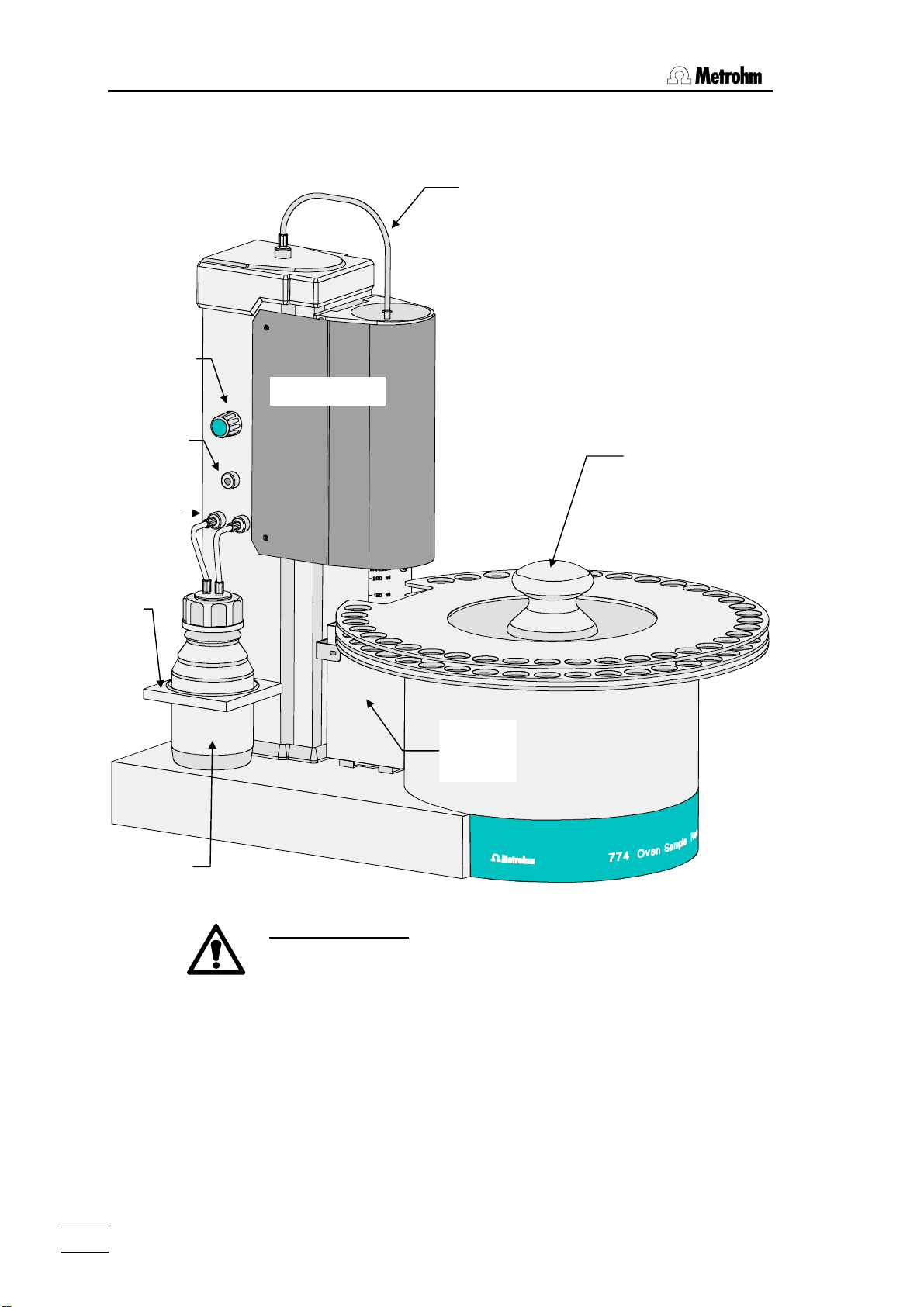
1.3.2 Oblique view from left-hand side
with protective cover in position
Flow regulator
Protective cover
Gas supply
Inert gas
Drying flask
connections
Holder for
drying flask
Drying flask with
molecular sieve
inlet
Sample rack
with grip
Oven with
protective
acket
Safety information:
The protective cover and the plug cover have to be in position for
safety reasons.
The plug cover prevent spilt solvents or chemicals from adversely
affecting the connections and interfaces.
4
774 Oven Sample Processor, Instructions for use
Page 11
1.3 Instrument description
p
/
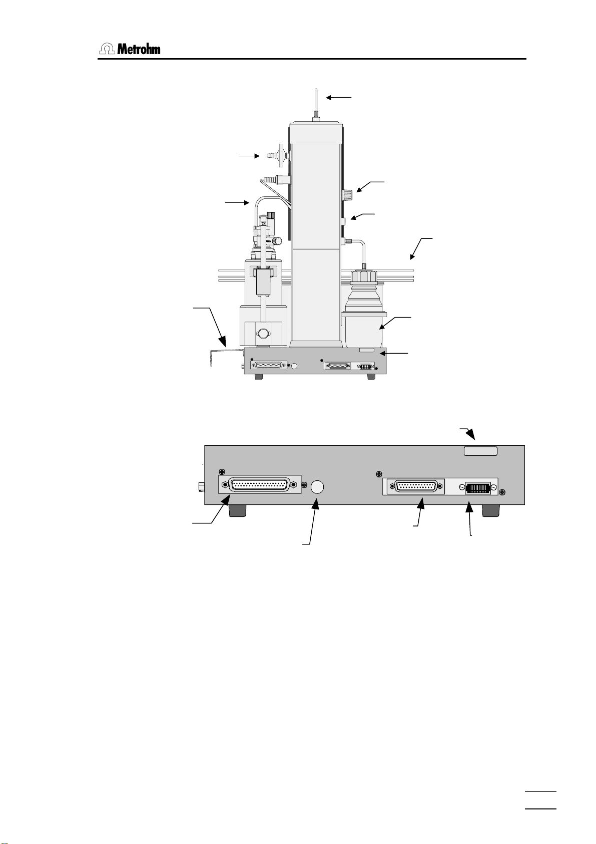
1.3.3 Rear view
Air inlet filter
Outlet heater
transfer tube
Plug
cover
Gas supply
Flow regulator
Inert gas inlet
Sample rack
Drying flask
External Bus
Address
1.3.4 The socket strip (rear panel):
External Bus
Address
External bus
connection
External bus
address
selector
The 'External Bus' address must be set to 0 (zero).
0000/ 00 00
Type 1.774._
RS 232 Keyboard
Made by Met rohm Herisa u Switzerl and
Serial number
Serial
RS 232 interface
Rear socket
stri
Type 1.774. _
RS 232
Made by Metrohm Heri sau Switz erland
0000/ 00 00
Keyboard
Keyboard
connection
774 Oven Sample Processor, Instructions for use
5
Page 12
1 Overview
(
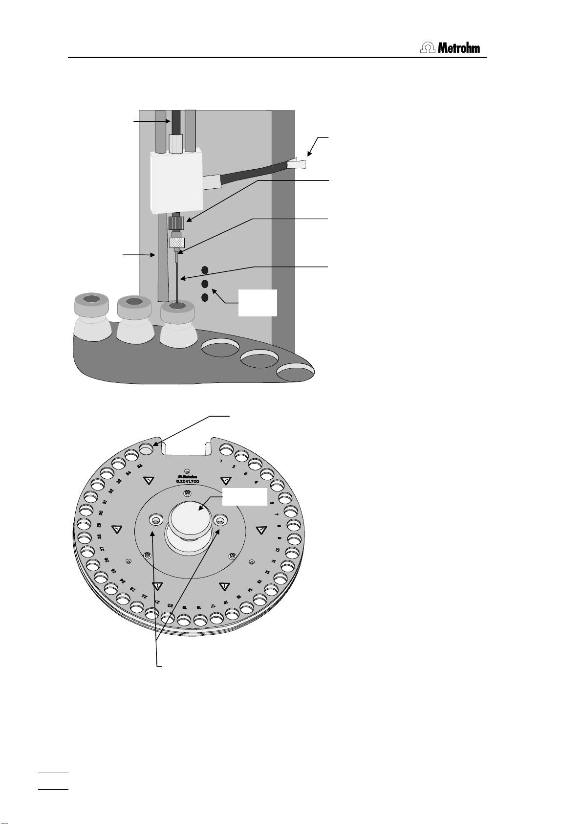
1.3.5 Guide head
Gas supply
(gas inlet)
Guide rod
(adjustable)
Infrared
sensors
Heated transfer hose
(outlet heating)
Needle adapter
made of PEEK
Hollow needle with
Luer connection
exhaust)
Hollow needle
(injection needle)
The tower of the 774 Oven Sample
Processor is equipped with infrared
beaker sensors which detect the
presence of a vial in front of the
tower. This "beaker test" is carried
out after every MOVE command.
1.3.6 Sample rack
Special position 1 (for conditioning vial)
.
d
on
C
.
os
P
Grip
Openings for
guide bolts
Warning!
If sample vials on the racks have just been processed
they could have a temperature above 200°C!
The removable sample rack offers
space for 35 sample vials and a conditioning vessel. A snap-in mechanism
ensures that the rack base is blocked
when the rack is removed so that no
sample vials can fall out. When the
rack is replaced this block is removed
so that the upper part of the rack with
the sample vials can be rotated.
The rack can only be exchanged in the
base position (recess in front of the
tower). The sample rack is moved to
the base position by pressing the
<RACK> key.
When replacing the rack take care that
it is positioned correctly. The guide
bolts of the turntable must be located
in the openings provided for them in
the sample rack. The recess of the
rack must surround the oven block.
6
774 Oven Sample Processor, Instructions for use
Page 13
1.3 Instrument description
When the sample rack is positioned the rod magnets on the base of the
rack are read in automatically. The arrangement of the magnets defines the
rack code, which is allocated to an internal position table with whose help
the 774 Oven Sample Processor recognizes the arrangement of the vial positions on the rack.
The above arrangement corresponds to the magnet code 000001.
1.3.7 Sample vials
The sample rack (order no. 6.2041.700) is intended for use with sample vials (order. no. 6.2419.000) with 21 mm outer diameter. Only these vials
guarantee optimal heat transfer between the oven block and the sample.
Use only septum seals with a PTFE insert (order. no. 6.1448.050), as these
are exposed to high temperatures. The sample vials must be tightly sealed
by using the septum closure crimpers.
Closures which are not sufficiently tight can cause significant errors in the
results. Closures which are not mounted properly may cause damage to
the injection needle.
774 Oven Sample Processor, Instructions for use
7
Page 14
2 Installation
2 Installation
2.1 Setting up the instrument
Packaging
The 774 Oven Sample Processor is supplied with the accessories in separate special packages designed to ensure maximum protection. These contain shock-absorbing foam linings. As only these special packages guarantee damage-free transport of the instrument, it is essential you store them in
a safe place.
Control
Immediately following delivery, check that the consignment is complete and
undamaged (compare with delivery note and accessories list in the Instructions for Use, page 155). In case of damage see "Warranty", page 154.
Setting up
The 774 Oven Sample Processor is a rugged instrument and may be used
in rough environments such as laboratories and manufacturing plants. It
must not be exposed to a corrosive atmosphere.
If the sample changer is operated in a rough environment, regular maintenance is strongly recommended.
2.2 Power supply
Follow these instructions to connect the 774 Oven Sample Processor to the power supply. Ensure that the instrument is never operated with incorrect voltage ratings and/or with fuses of an incorrect
rating, otherwise there is a fire hazard!
Setting the instrument supply voltage
Before switching on the 774 Oven Sample Processor for the first time,
check that the line voltage set on the instrument (see next page) matches
the local power supply voltage. If this is not the case, change the voltage
setting as follows:
• Disconnect line cable
Unplug the 774 Oven Sample Processor.
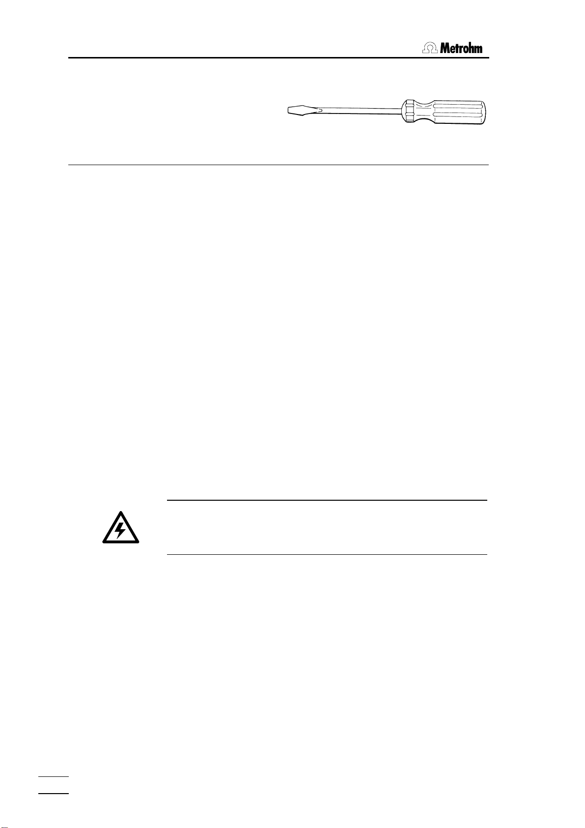
Remove fuse holder
Using a screw driver, loosen the fuse holder and pull it out.
774 Oven Sample Processor, Instructions for use
8
Page 15
2.2 Power supply
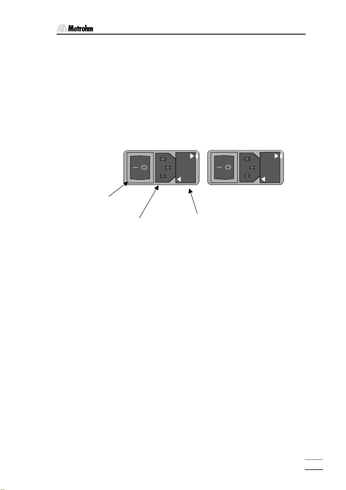
Power switch
• Checking and replacing fuse
Carefully remove the built-in fuse and check its specifications. (The position of the fuse in the fuse holder is marked by the white arrow printed
next to the supply voltage):
2.0 A (slow) ord. no. U.600.0019
• Replace fuse
Replace fuse if necessary and reinsert it in the fuse holder.
• Insert the fuse holder
Insert the fuse holder according to the appropriate supply voltage. The
white arrow besides the desired voltage has to point towards the white
block mark printed on the fuse holder's panel (see below).
220 – 240 V
100 – 120 V
100
-
120 V
240 V
-
220
220 - 240 V
Power plug Fuse holder
100 - 120 V
774 Oven Sample Processor, Instructions for use
9
Page 16
2 Installation
2.3 Safety considerations
• Do not operate the 774 Oven Sample Processor without protective covers.
The plug cover protects the connectors from spillage. Organic solvents
are always a potential serious fire hazard.
The protective cover of the guide head prevents the access to the stroke
path of the injection needle. Never get your hand beneath the protective
cover while operating the instrument.
• If you work with inflammable samples the 774 Oven Sample Processor
has to be operated under a safety hood. In addition to that you have to
use nitrogen or another inert gas instead of the integrated air pump. See
chapters 2.2.4 and 4.2.
• Always wear safety goggles while working with the 774 Oven Sample
Processor.
The oven can reach 250 °C and more. The heating block is covered by
a protective jacket. Keep your hands off the heated oven or the sam-
ple in work. Do not reach under the protective cover.
Caution! Just after processing sample vials may be hot, too. Even parts of
the sample rack can reach elevated temperature up to 60 °C.
• Allow the sample vials to cool off before removing vials from the rack or
detaching the sample rack .
The 774 Oven Sample Processor may be used for sample processing with
extraction methods at higher temperatures. These kinds of method require
special safety precautions.
Before working with inflammable organic solvents read the relevant
safety sheets or consult common accessible safety literature.
• Do not heat organic solvents to their flash point!
• Use nitrogen or another inert gas.
If failure or malfunctioning occurs during operation of the 774 Oven Sample
Processor, it is recommended to first search for the cause with the help of
the diagnostic functions (see Instructions for Use, page 143). If this is of no
help in rectifying the disorder or the cause of the malfunction cannot be
identified, the Metrohm Service Department should be consulted.
774 Oven Sample Processor, Instructions for use
10
Page 17
2.4 Arranging the accessories
If opening the instrument is unavoidable, the following safety precautions
are to be strictly adhered to:
Before opening the instrument disconnect it from all electrical
sources. Make sure that the power plug has been pulled out.
Only in exceptional cases should the instrument be opened while it is
switched on. Because parts that conduct current are exposed in this case,
this should only be undertaken by an expert who is acquainted with the associated dangers.
Electronic components are sensitive to static electricity and can be destroyed by discharge. Before touching any components inside the instrument, both the person and his tools should be grounded by grasping a
grounded object (for example: a metallic part of the casing of the instrument or a radiator) in order to eliminate any static electricity.
When peripheral instruments are connected to the 774 Oven Sample Processor, the sample changer and the instruments to be connected have to be
switched off, otherwise all instruments could suffer damage.
If it becomes apparent that the instrument can no longer be operated safely
it must not be used at all.
2.4 Arranging the accessories
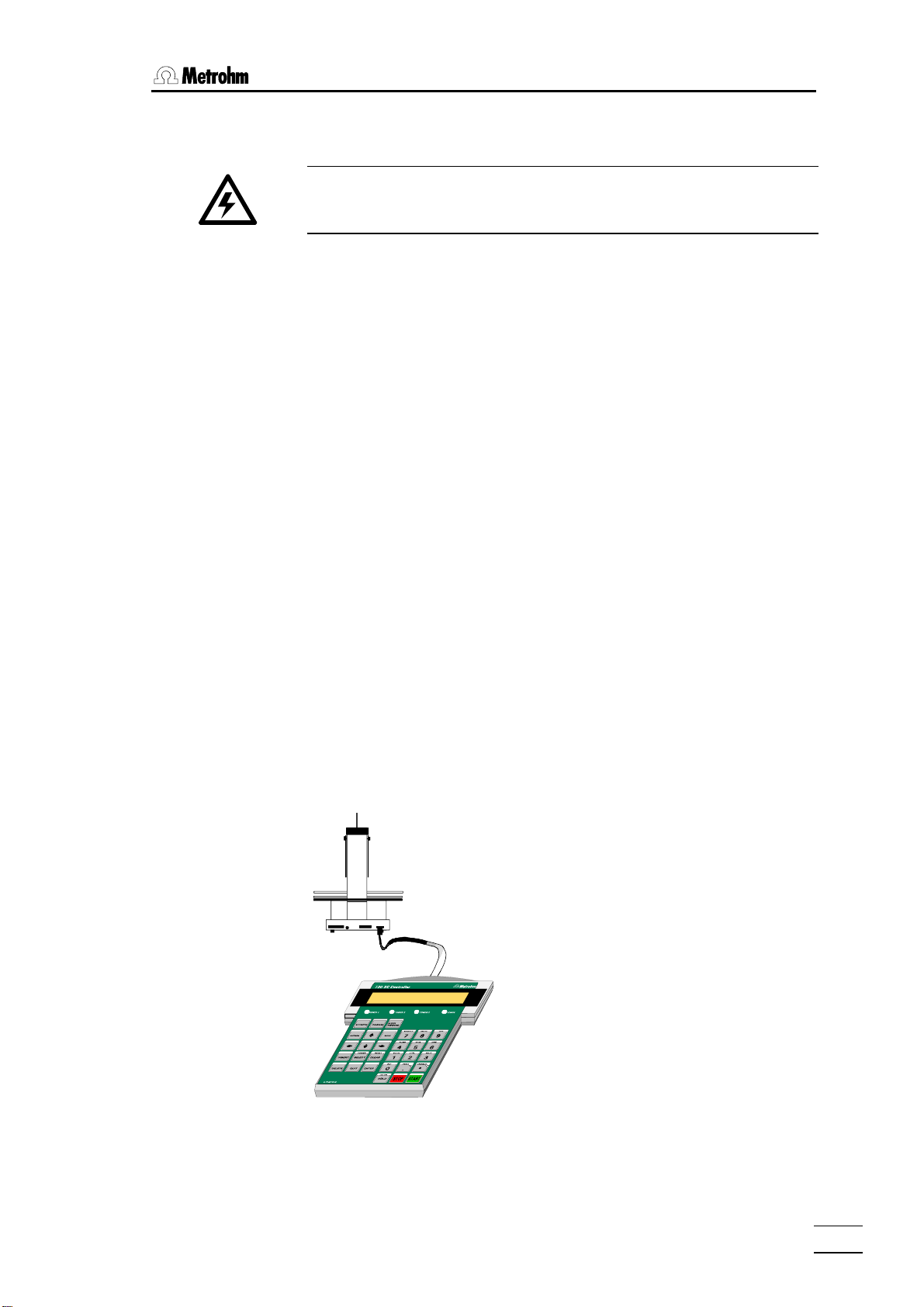
2.4.1 Connecting the keyboard
The keyboard is connected to the
keyboard socket at the rear of the
sample changer. To disconnect
press the plug together slightly on
both sides.
774 Oven Sample Processor, Instructions for use
11
Page 18
2 Installation
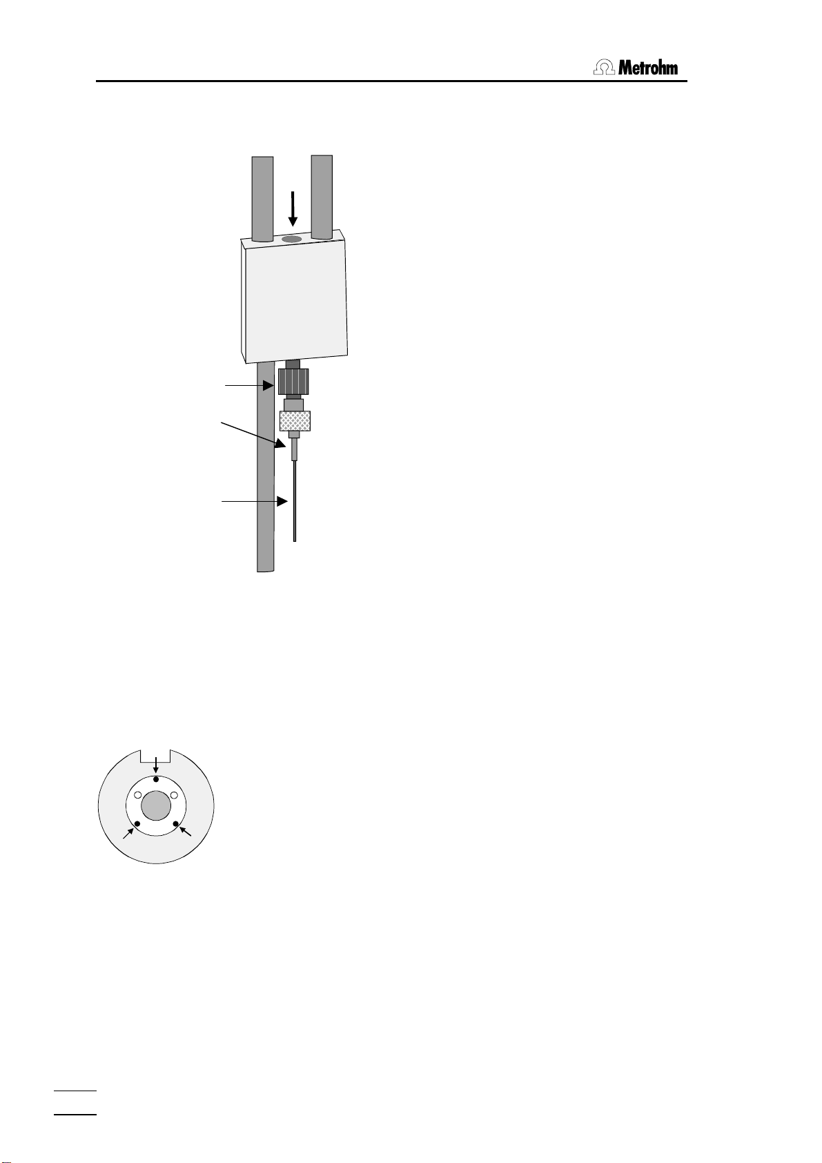
2.4.2 Equipping the guide head
• Screw the needle adapter (6.1808.150) onto the
bottom of the guide head.
• Attach the outlet hollow needle (6.2816.060) to the
Luer connection of the needle adapter.
• Carefully introduce the hollow injection needle
Guide head
Needle adapter
Hollow outlet
needle
Hollow injection
needle
(6.2816.050) into the guide head from above (see
arrow). Pull the needle downwards to the full extent.
• Now lead the gas inlet (6.1805.470) through the
lift head from above and screw it onto the guide
head (see arrow). Connect the other end of the
tubing to the gas outlet opening on the top of the
tower. Take care that the connections are tight.
If necessary, the injection needle may be lifted by attaching
the PTFE spacer ring (that is supplied with) to the needle.
If you wish to avoid the penetration of the sample by the
needle, you may lift the injection needle by the use of two
different M6/M8 adapters (order no. 6.1808.040 and
6.1808.090). The injection needle must only puncture the
vial's seal by a few milimeters.
2.4.3 Adjusting the sample rack
• Check the positioning of the sample rack. After switching on the 774
Oven Sample Processor place the rack on the instrument and let it move
to the first sample position by pressing the <Í> key. The circular
opening of sample position 1 of the rack must coincide with the opening
of the oven block beneath it.
• If this is not the case then loosen the three Allen screws (see diagram) on
the sample rack. Carefully adjust the upper part of the rack and then retighten the Allen screws.
• Now place a sample vial with a septum cap closure in sample position 2
and press the <Í> key again. By carefully pressing the <Ð> key to
lower the lift it is now possible to check whether the penetration needle
correctly penetrates the center of the sample vial septum and that the vial
is pressed down into the oven opening without tilting.
Warning!
Do not lower the needle too far. It must not contact the base of the vial and
become bent.
• Press the <RACK> key in order to return the sample rack and lift to the
starting position.
• Readjust the sample rack, if necessary.
774 Oven Sample Processor, Instructions for use
12
Page 19
2.4 Arranging the accessories
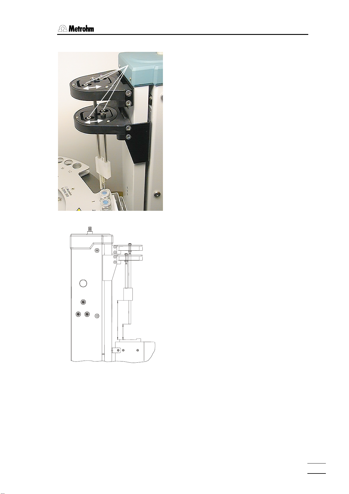
2.4.4 Adjusting the needle position
In addition to the adjustment of the sample rack, the
Allen screws
position of the needle (radial positioning) may be
adjusted.
After the adjustment of the sample rack proceed as
follows:
1. Place a sealed beaker under the needle.
2. Lower the needle on to the seal.
3. Loosen the Allen screws of the sliding de-
4. Position the needle in the centre of the seal.
5. Fasten the sliding devices.
6. Press <RACK>. The instrument moves to
7. Remove rack.
vices.
initial position.
Positioning the needle
±1,5
111
±1
44
Distances of the guide head and rod
(in mm)
8. Check the distances according to the drawing on the right and adjust if necessary.
774 Oven Sample Processor, Instructions for use
13
Page 20
2 Installation
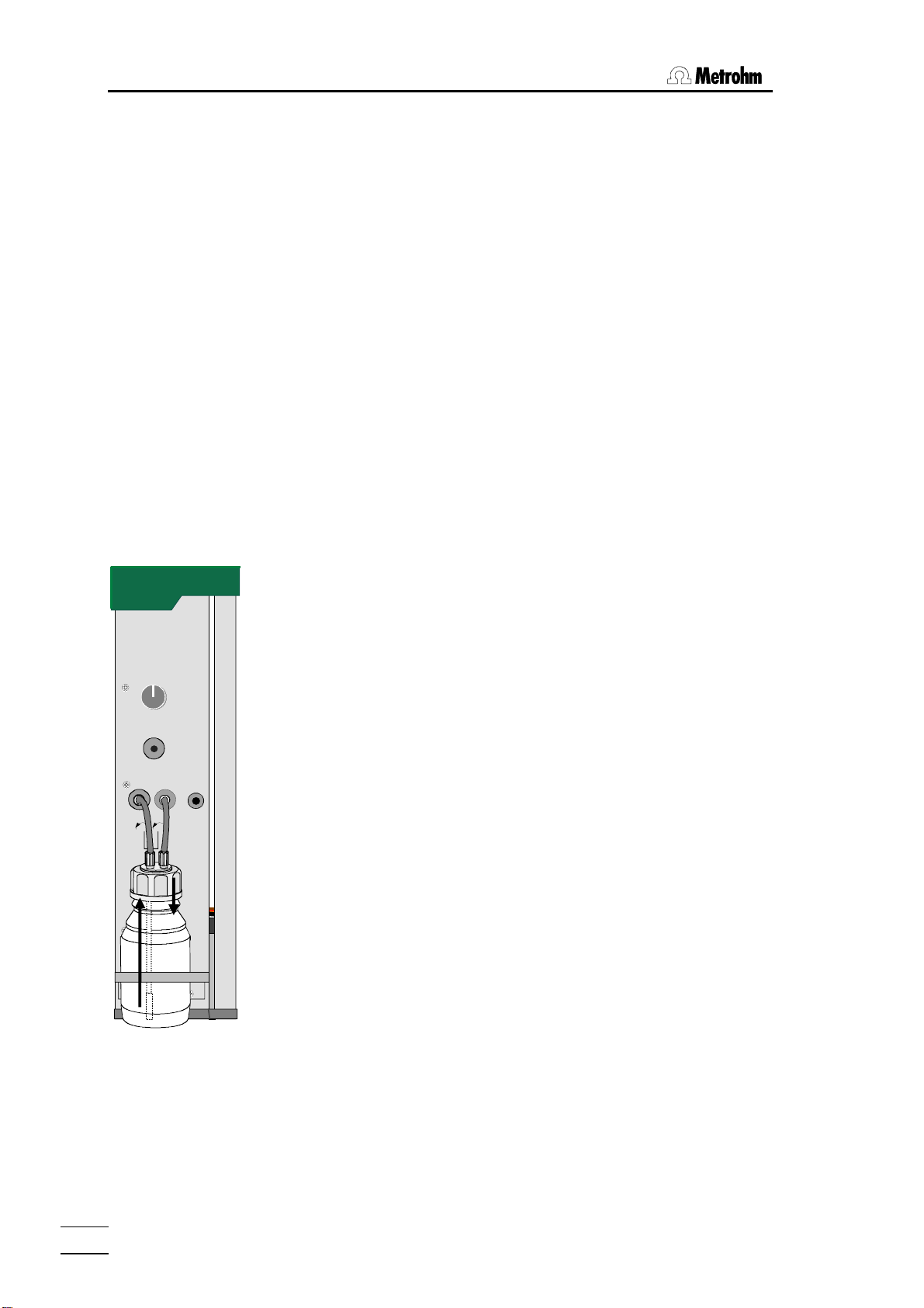
2.4.5 Installation of the tubing system and the drying flask
A stream of gas with a constant flow rate is required to transfer the moisture
which is released when the sample is heated to a measuring vessel. You
can either use the built-in pump to supply air or use an inert gas such as nitrogen for this purpose.
Inert gas connection
Connect the inert gas to the 'Air/N
the instrument. Make sure that the pressure in the supply line is less than 1
bar. The inert gas should be dried by passing it through the drying flask.
The flow rate is measured and monitored by the 774 Oven Sample Processor. A solenoid valve is used to switch the gas flow on and off.
Air supply from the built-in pump
A stream of air can be used for the determination of chemically and thermally stable samples. The pump built into the tower of the 774 Oven Sample Processor provides a sufficiently large and stable flow rate.
It is essential that the flow of gas is dried and filtered. If the pump is used
the air is drawn in through the right-hand side of the instrument. A dust filter
(6.2724.010) should be mounted on the 'Inlet filter' connection. The gas is
dried by mounting a drying flask on the left-hand side of the instrument, as
shown in the drawing alongside.
Gas flow
The drying flask is filled with molecular sieve and the outlet tube
(6.1821.050) with its filter is fitted to the drying flask insert (6.1602.140).
2 in
Air/N
Screw the completely assembled insert onto the drying flask and attach the
two tubing connections (6.1805.520, 7 cm long) to the drying flask cap.
Place the flask in the drying flask holder and then attach the free ends of
from to
the tubing connections to the corresponding connections on the tower of
the 774 Oven Sample Processor. The tubing connected to the inlet tube in
Drying flask
the drying flask is connected to the left-hand connection marked 'from
Drying flask'. The carrier gas will stream into the head space of the flask
and penetrate the molecular sieve. Then it can stream up inside the outlet
tube and enter the tower's gas tubings via the 'from Drying flask' connector'.
The filling of the drying flask must be replaced from time to time. The interval
may vary depending on the length of use, moisture content of the gas and
atmospheric humidity. Read the information given on the label of the molecular sieve container for more details.
in' connection on the left-hand side of
2
774 Oven Sample Processor, Instructions for use
14
Page 21
2.5 Integration
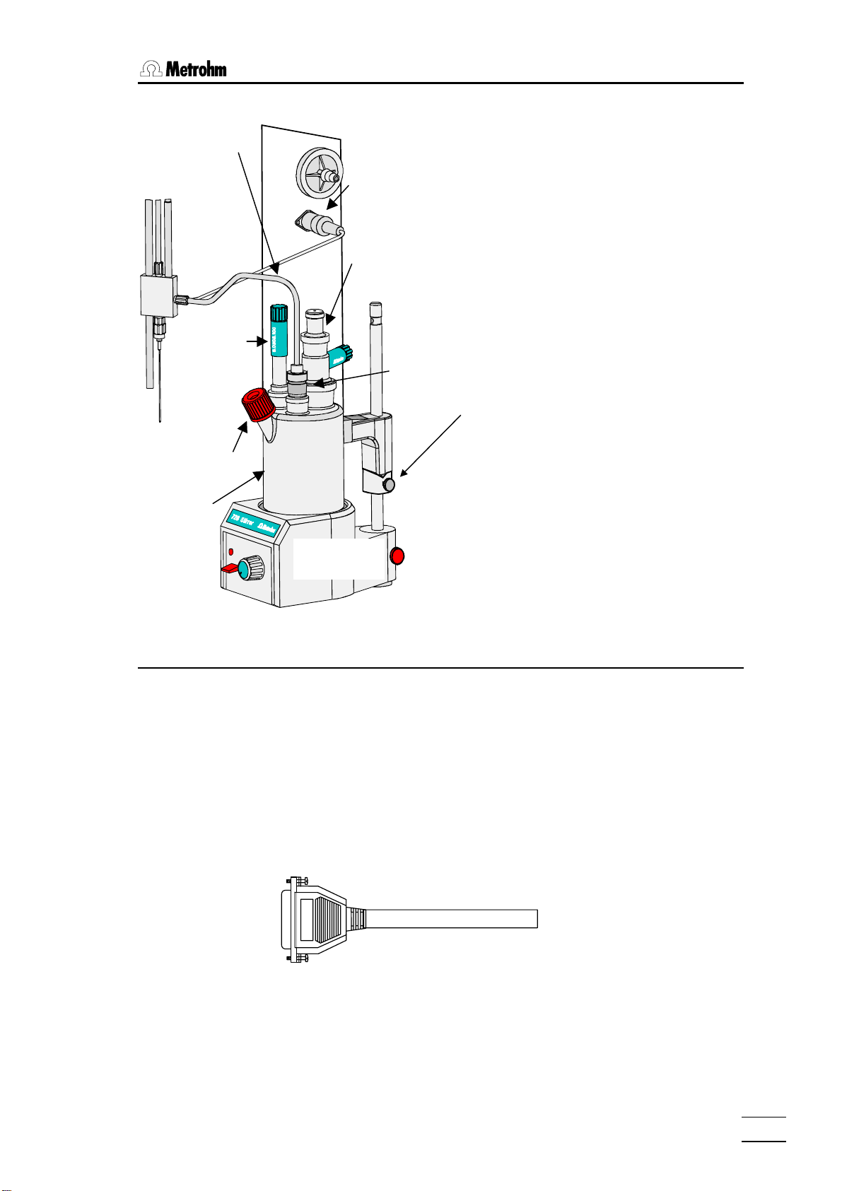
2.4.6 Installation of the measuring cell
Transfer hose with
outlet heating
Indicator
electrode
Septum
stopper
6.1464.320
Titration vessel
Connection for
outlet heating
r
e
t
a
e
h
t
l
e
u
t
O
Generator
electrode with
drying tube
728 Magnetic
stirrer
Stopper with
6.1446.170 O-ring
Example: 6.1464.320 Coulometer titration vessel
Install the necessary accessories as shown in
the diagram alongside.
The fastening screws can be used to permanently fix the whole assembly in position.
If you wish to automate the reagent changing
process (aspiration and dosing) then the Coulometer titration vessel with two side-mounted
threaded openings (6.1465.320) should be
used.
If volumetric KF determinations are to be carried out a suitable titration vessel should be
selected (see Metrohm accessories catalog)
together with the KF titration vessel upper part
(6.1414.030). Instead of the 6.1446.170 stopper use the nipple and O-ring of the
6.2730.030 stopper to introduce the transfer
hose into the titration vessel.
Fastening screws
2.5 Integration
Cables
Connecting peripheral instruments to the 774 Oven Sample Processor requires Metrohm cables. Otherwise safe data transmission may not be
guaranteed.
Remark:
Metrohm cables are labeled with the type of the instrument which they may
be connected with and optionally with the particular socket. Look at the cable ends. For example:
All instruments have to be switched off before they are connected.
Otherwise the instruments could be damaged.
Titrino B
692 / 712 / 713
774 Oven Sample Processor, Instructions for use
15
Page 22
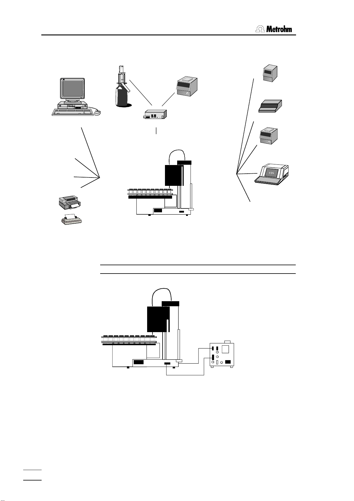
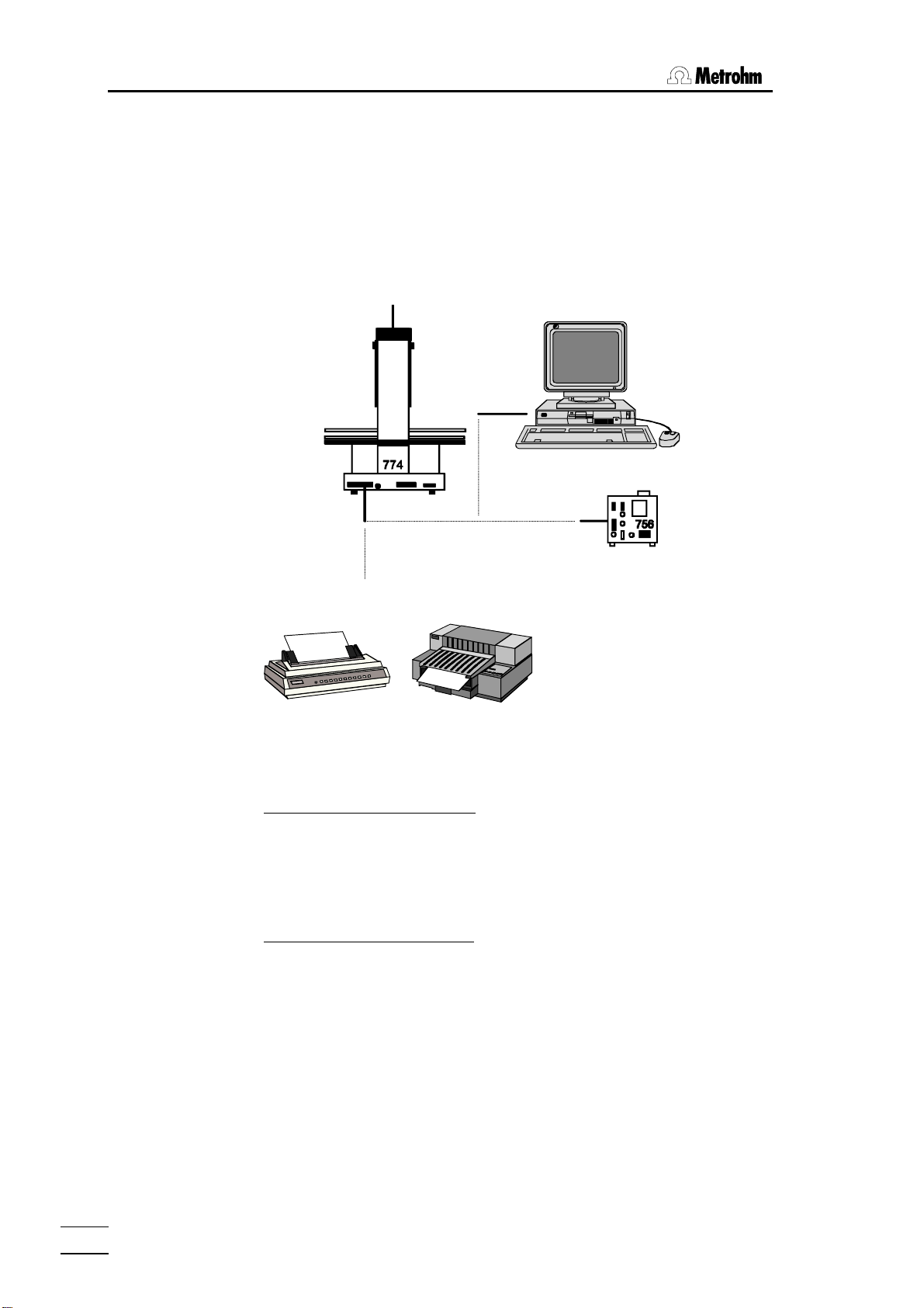
2 Installation
The 774 Automation System
700 Dosino 685 Dosimat
756 Coulometer
684
737
701
...
784
PC software
Metrohm-
instruments
729
729 Dosimat Interface
External Bus
Coulometer
Titrino
family
other
instruments
printers
Seiko
Citizen
Epson
HP
IBM
…
RS 232
774
774 Oven Sample Processor
2.5.1 Remote connections
774 Oven Sample Processor — 756 Coulometer
for coulometric determinations
Remote
726 Titroprocessor
other
instruments
6.2125.110
cable (RS232)
774
756
6.2141.020
cable (remote)
Control of the 756 Coulometer is carried out via the control lines of the remote connection.
While a sequence is being processed the 774 Oven Sample Processor can,
via the serial RS232 interface, cause the 756 Coulometer to load a particular method. When drawing up a report the 756 Coulometer automatically
obtains the temperature of the 774 Oven Sample Processor via the RS232
connection.
774 Oven Sample Processor, Instructions for use
16
Page 23
2.5 Integration
Control commands of the 774:
CTL:Rm : START Gerät1 starts Coulometer
CTL:Rm : *************1 "
CTL:RS &U.R.N loads a method in the Coulometer
CTL:RS "774BLANK"..$G here e.g. "774BLANK"
Scanning the remote lines of the 774:
SCN:Rm : **0**010 waits for 'cond. ready'
SCN:Rm : *****000 waits for end of determination
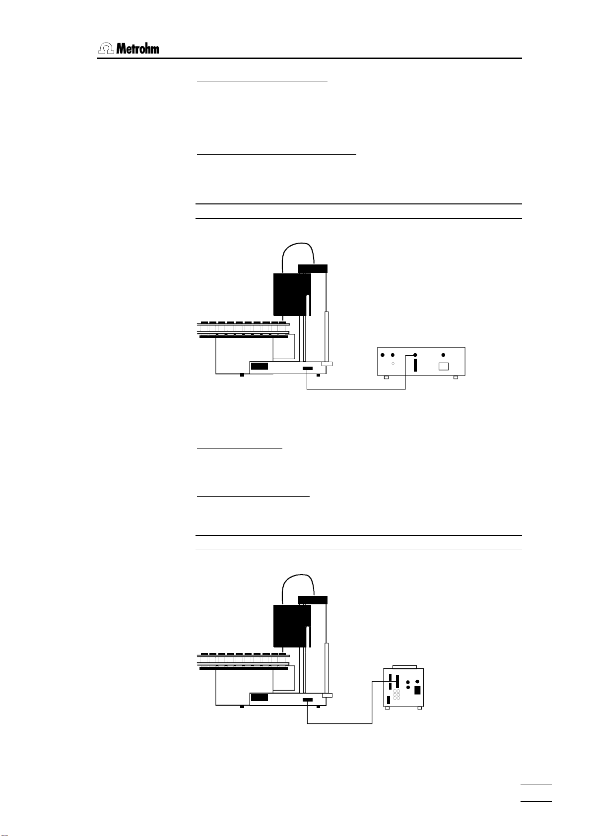
774 Oven Sample Processor — 737 Coulometer
for coulometric determinations
774
737
6.2141.000 cable (remote)
The 737 Coulometer is completely controlled via the remote lines.
Control commands:
CTL:Rm: *********1**** starts Coulometer with
CTL:Rm: *********0**** a start impulse
Scanning via remote lines:
SCN:Rm : 10000100 waits for 'cond. ready'
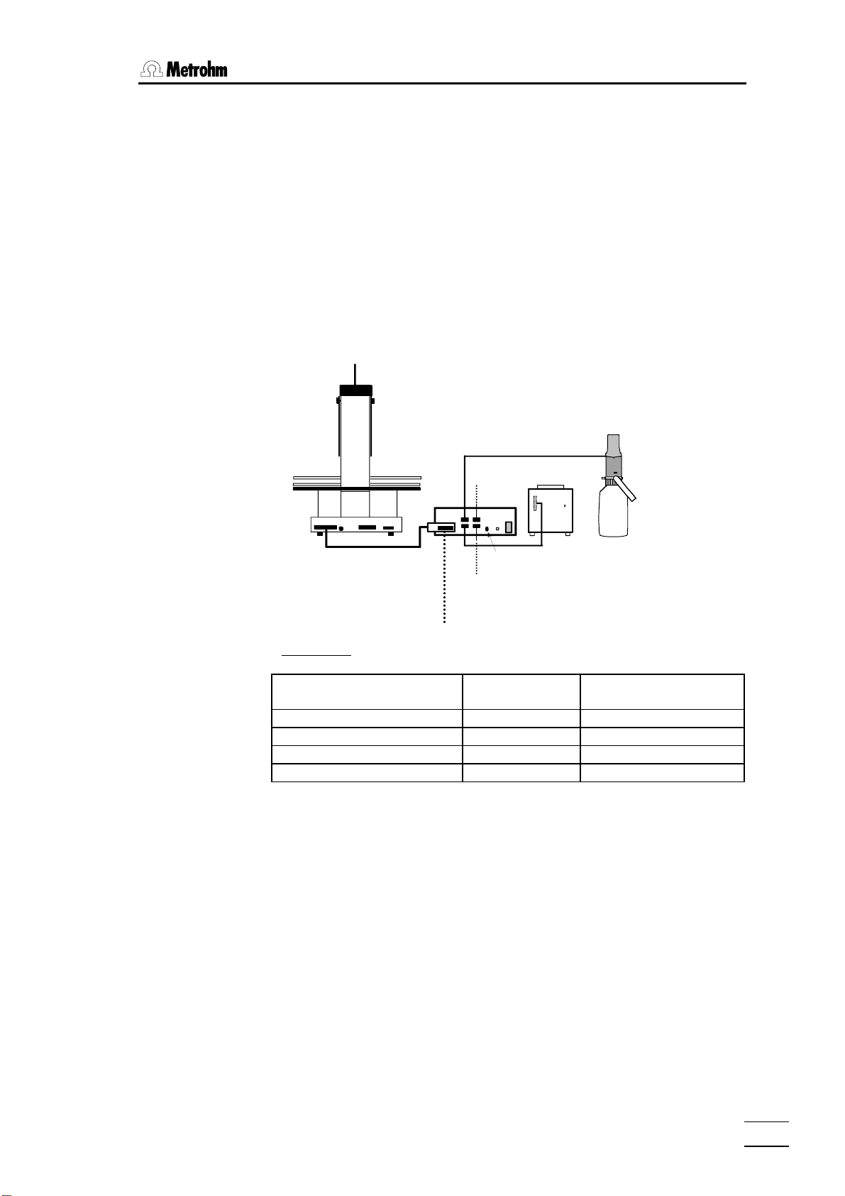
774 Oven Sample Processor — 7xx Titrino
for volumetric KF titrations
774
774 Oven Sample Processor, Instructions for use
6.2141.020
cable (remote)
758
17
Page 24
2 Installation
Control commands:
CTL:Rm : START Gerät1 starts Titrino
CTL:Rm : ***********1** advance impulse / ENTER
Scanning via remote lines:
SCN:Rm : ****1000 waits for end of titration (EOD-impulse)
SCN:Rm : *****010 waits for 'cond. ok'
In principle it is possible to use an additional RS232 connection to automatically load a particular method in the Titrino while a sequence is being
processed. Please refer to the example of the remote connection given for
the 756 Coulometer on the previous page.
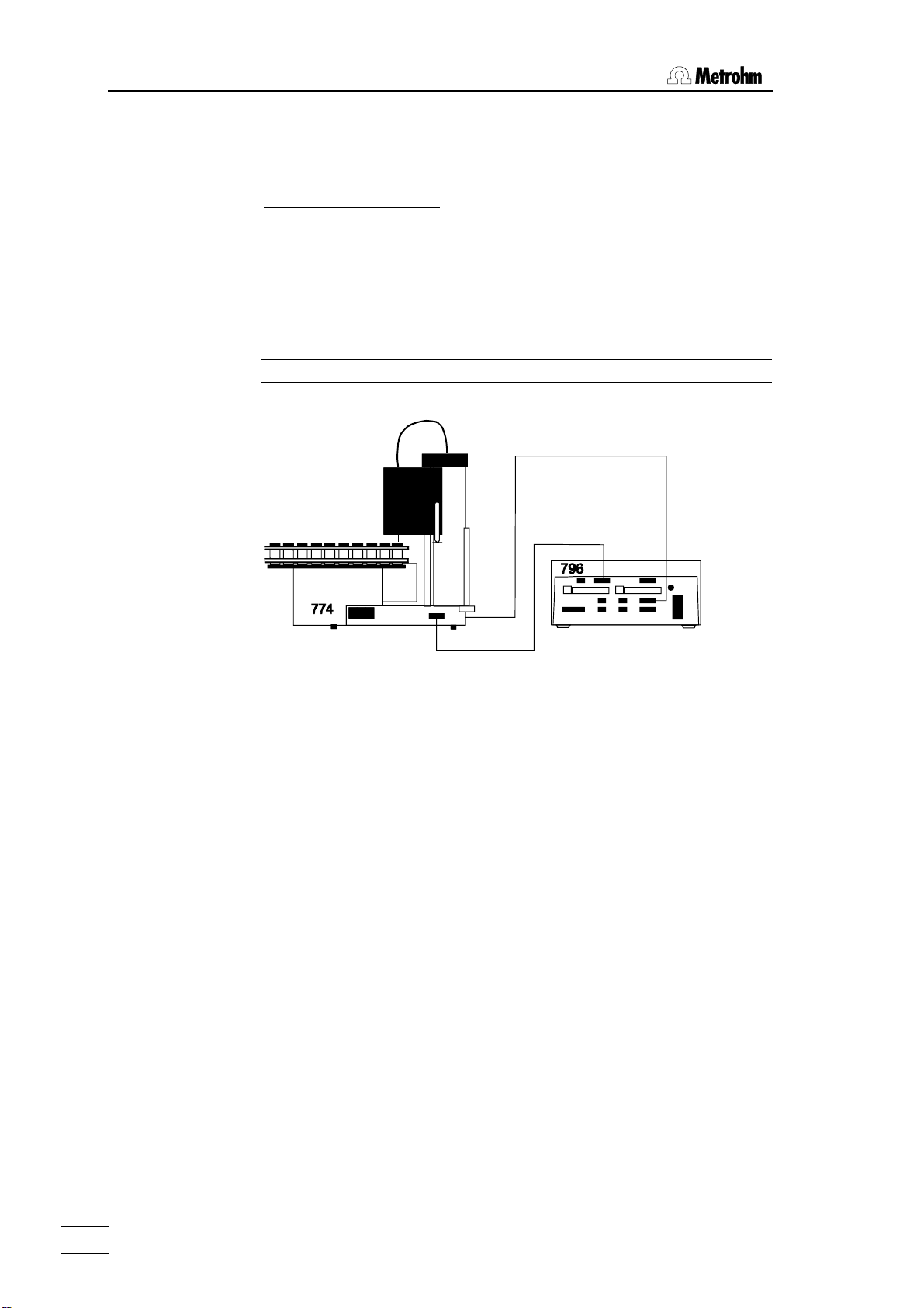
774 Oven Sample Processor — 796 Titroprocessor
for volumetric KF titrations
6.2125.110
cable (RS232)
6.2141.020
cable (remote)
or
If connected to a 774 Oven Sample Processor the 796 Titroprocessor takes
over the functions of the control instrument itself (Master). The communication between the 774 Oven Sample Processor and the 796 Titroprocessor
can be solved in any manner.
If a remote connection is used (6.2141.020 cable) the input and output lines
0…7 can be used as required. However, it is then not possible to start a
774 Oven Sample Processor method. See page 79ff for the communication
commands.
A serial RS232 connection between the 796 Titroprocessor and the 774
Oven Sample Processor has the advantage that the Titroprocessor as control unit can access all internal functions except starting or loading a
method in the 774 Oven Sample Processor. Please refer to the description
of the Metrohm remote language and the 774 remote control tree on page
98ff.
774 Oven Sample Processor, Instructions for use
18
Page 25
2.5 Integration
2.5.2 External bus connections
If a KF Titrino or a Coulometer which does not support automatic solvent
changing is connected to the 774 Oven Sample Processor then this can be
carried out with the help of a 700 Dosino. 685 Dosimats can also be used
for the addition of solvents. 700 Dosinos or 685 Dosimats are connected to
the 774 Oven Sample Processor via the so-called 'External Bus'.
A 729 Dosimat interface can be used to connect up to 4 dosing devices to
the 'External Bus' interface. Up to 3 Dosimat interfaces can be switched in
line (cascaded) and equipped with further dosing instruments. The instrument address must always be set correctly at the interfaces. In this way it is
possible to operate up to 12 dosing instruments directly with the 774 Oven
Sample Processor with the aid of the DOS command.
Dos. 1
685
Dos. 2
6.2134.000 cable
774
6.2135.000 cable
729
Dos. 4
Dos. 3
EBus
address 1
Addresses:
'External Bus'-
address
774 Oven Sample Processor 0
1st interface 1 Dos. 1 … Dos. 4
2nd interface 2 Dos. 5 … Dos. 8
3rd interface 3 Dos. 9 … Dos. 12
700
Dosing instrument
774 Oven Sample Processor, Instructions for use
19
Page 26
2 Installation
2.5.3 Serial connection (RS232)
Many different instruments may be connected via the serial RS232 interface. In addition to all Metrohm instruments that support the Metrohm remote control language (see page 101ff) any printer with serial interface (or
parallel interface and parallel/serial converter) or a personal computer (PC)
may be connected. Any other measuring instrument may be controlled via
RS232 interface, as long as it supports serial data transmission.
6.2125.060 cable
Printer cables see page. 20f
In order to guarantee safe data transmission, it is important to set the same
RS232 interface parameters correctly for both instruments connected (see
page 21f).
Control commands (examples):
CTL:RS &M;$G starts a Metrohm instrument
CTL:RS &M;$S stops a Metrohm instrument
PRINT: config
Scanning input data (example):
SCN:RS : *R" waiting for readiness of a Metrohm instru-
Information about the settings and cables required for connecting a printer
is given in the following section.
prints a configuration report to a printer or
PC
ment
774 Oven Sample Processor, Instructions for use
20
Page 27
2.5 Integration
2.5.4 Connecting a printer
Printers with the following printer emulations may be connected:
IBM IBM Proprinter and printers with IBM emulation
Epson Epson printers and printers with Epson emulation
Seiko Seiko printer DPU-411/414
Citizen Citizen printer IDP560 RS
HP
HP printers and compatibles with HP PCL3 emulation
If you connect a printer not listed in the following table, be sure that it is able
to emulate Epson or IBM Proprinter mode.
Use the 6.2125.050 cable for connecting a printer with built-in serial interface. Printers with parallel interface require the 2.145.0300 serial/parallel
converter and 6.2125.020 cable.
Before connecting a printer to the RS232 interface, switch off the
774 Oven Sample Changer.
The parameters of the RS232 interface are accessible in the configuration
menu under '>RS232 settings'.
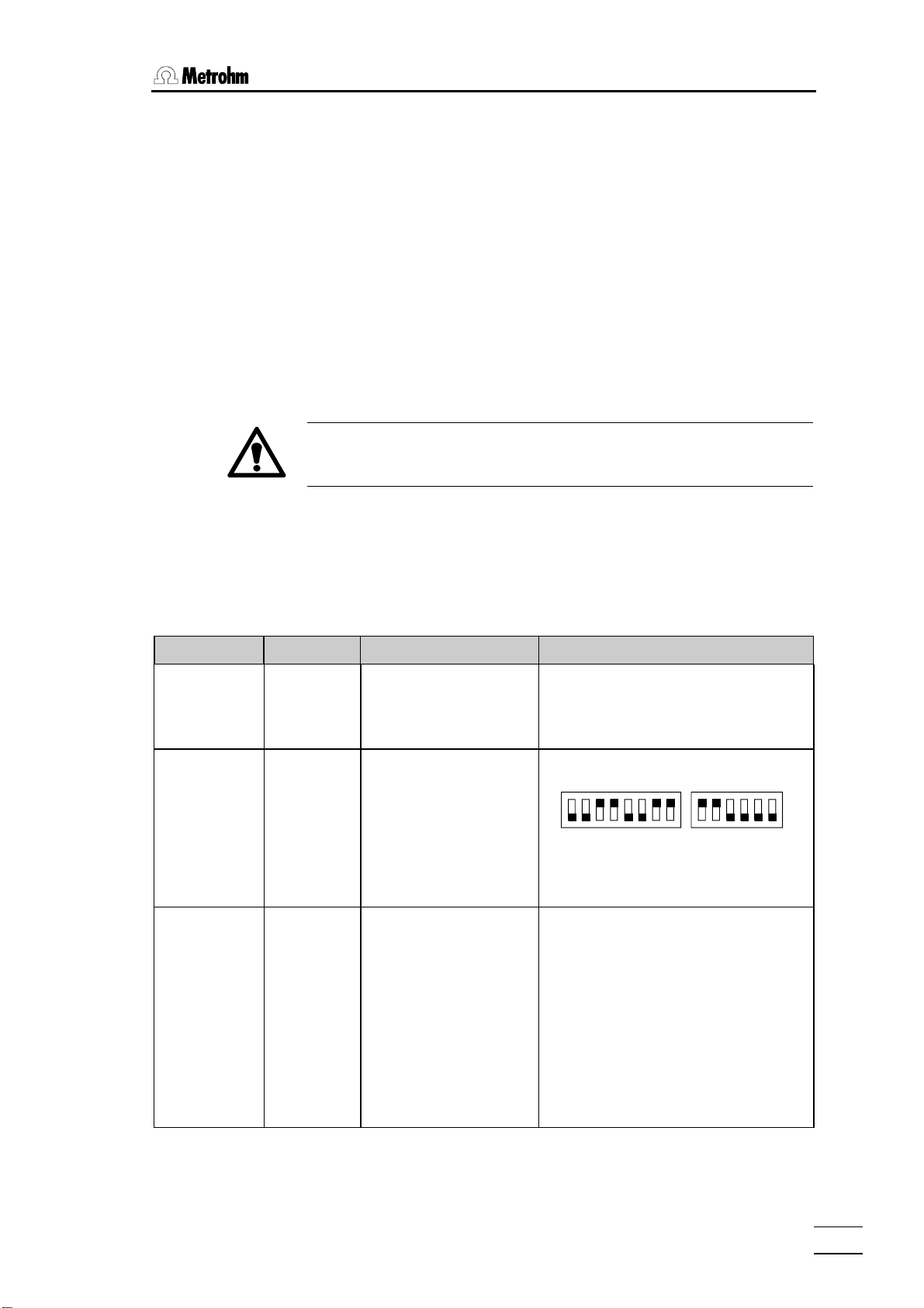
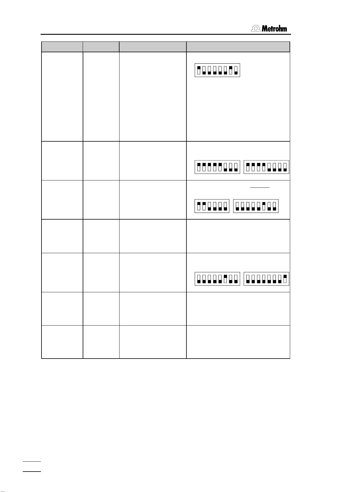
The following table lists the information necessary for connecting a printer:
Printer type Cable RS232 Settings Settings on Printer
IBM Proprinter 6.2125.050
Seiko
6.2125.020
DPU-411
Seiko
6.2125.130
DPU-414
baud rate: 9600
data bit: 8
stop bit: 1
parity: none
handshake: HWs
character set: IBM
baud rate: 9600
data bit: 8
stop bit: 1
parity: none
handshake: HWs
character set: Seiko
baud rate: 9600
data bit: 8
stop bit: 1
parity: none
handshake: HWs
character set: Seiko
see printer manual
DIP switch settings:
DIP01 DIP02
on
off
12345678
The 7-bit ASCII character is set automatically to the specific national character set
according to the selected dialog language.
Recommended DIP switch settings
Dip SW-1 Dip SW-2 Dip SW-3
1 OFF ON ON
2 ON OFF ON
3 ON ON ON
4 OFF ON ON
5 ON ON OFF
6 OFF ON ON
7 ON OFF ON
8 ON OFF ON
The 7-bit ASCII character is set automatically to the specific national character set
according to the selected dialog language.
123456
774 Oven Sample Processor, Instructions for use
21
Page 28
2 Installation
Printer type Cable RS232 Settings Settings on Printer
Citizen
IDP560-RS
6.2125.050
baud rate: 9600
data bit: 8
stop bit: 1
parity: none
handshake: HWs
character set:Citizen
DIP switch settings:
on
off
12345678
The 7-bit ASCII character is altered to the
specific national character set by setting
the jumpers J1 and J2 as follows:
J1 J2 character set
open open USA
closed closed Great Britain
closed. open France
open closed Germany
No Spanish character set available
(French may be best).
Epson
6.2125.040
with 6-pole
round plug
Epson
6.2125.050
with additional
serial interface
#8148
Epson LX-300 6.2125.050
HP Deskjet
with built-in
serial interface
6.2125.050
or cable 25pole neg. /
9-pole pos.
(e.g. HP
C2933A)
HP Laserjet
with built-in
serial interface
cable 25pole neg. /
9-pole pos.
(e.g. HP
C2933A)
HP Deskjet /
Laserjet
with parallel
interface
6.2125.020
+ serial/
parallelconverter
2.145.0300
baud rate: 9600
data bit: 8
stop bit: 1
parity: none
handshake: HWs
character set: Epson
baud rate: 9600
data bit: 8
stop bit: 1
parity: none
handshake: HWs
character set: Epson
baud rate: 9600
data bit: 8
stop bit: 1
parity: none
handshake: HWs
character set: Epson
baud rate: 9600
data bit: 8
stop bit: 1
parity: none
handshake: HWs
character set: HP
baud rate: 9600
data bit: 8
stop bit: 1
parity: none
handshake: HWs
character set: HP
baud rate: 9600
data bit: 8
stop bit: 1
parity: none
handshake: HWs
character set: HP
DIP switch settings:
SW1 SW2
on
off
12345678
12345678
DIP switch settings on the Interface:
SW1 SW2
on
off
123456
12345678
see printer manual
DIP switch settings :
A B
on
off
12345678
12345678
see printer manual
see printer manual*
* character set PC-8 is required.
PCL3 command: esc(10U
774 Oven Sample Processor, Instructions for use
22
Page 29

3.1 Configuration
3 Introduction
3.1 Configuration
The 774 Oven Sample Processor must be configured correctly before it is
used for the first time. This includes both the basic settings with the oven
settings and the configuration of the sample rack and the peripheral devices which are connected. All these settings are accessible via the configuration menu which can be opened with the <CONFIG> key. It is arranged in various submenus according to subject. Navigating (selecting the
individual settings) in the menu is carried out with the cursor keys (<Ð>,
<Ï>) and is also possible with the <HOME>, <END> and <ENTER>
keys. Submenus and main menus are exited with the <QUIT> key. In
many menu entries the <SELECT> key can be used to select the required
entry from a list of entries. These menu items are marked with a colon (:).
Further details are given on page 58.
When the configuration has been altered a RESET should be carried out
with <CLEAR> or the oven sample changer should be switched off and
on in order to ensure that the alterations become effective.
3.1.1 Basic settings
The basic settings which can be set in the submenu '>auxiliaries' include:
• dialog language
• display contrast
• beeper on/off for warnings
• Instrument identifier (instrument name or identification)
• program version
• maximum lift height and way
• beaker sensor on/off.
dialog
The dialog language can be selected from 'deutsch, english, français,
español'.
display contrast
The display contrast can be set on a scale from 0 (low contrast) to 7 (high
contrast).
beeper on/off
With error messages or when a value has been entered and not confirmed
with <ENTER> (and as a result is not accepted) then an acoustic signal is
produced. This signal can be switched off.
774 Oven Sample Processor, Instructions for use
23
Page 30

3 Introduction
device label
In order to be able to identify each particular laboratory instrument unambiguously (required by GLP) the sample changer can be given an 8-character
identifier made up of letters and/or numbers. Text input is described on
page 59.
program version
The program version (instrument software) cannot be altered. It is shown in
the configuration menu for information.
max. lift way
The maximum lift way is an important safety entry. If a correct entry is made
this ensures that the lift with the working head cannot be moved down too
far; this could cause damage to the needle or the sample vessel. The lowest lift position to be reached can be entered in mm (measured from the
upper stop position).
A convenient way of determining this position is to set the required height
manually (normal state) with the <Ð> and <Ï> keys. The configuration
menu is then opened and the current lift position in the display can be accepted in the menu entry 'max. lift way' with the <CLEAR> key.
Important: the entered value only becomes effective after a RESET or
when the instrument is switched off and then on again.
beaker sensor
The tower of the 774 Oven Sample Processor is equipped with an infraredbeaker sensor which detects the presence of a sample vial in front of the
tower. If the beaker sensor is switched on then this test will be carried out
after each MOVE command.
This entry also only becomes effective after a RESET or when the instrument is switched off and then on again.
3.1.2 Oven settings
The basic settings for the oven affect the various temperatures.
initial temperature
Entry of an initial temperature means that the oven is heated up to the set
temperature immediately after the 774 Oven Sample Processor is switched
on. The initial temperature can also be used as a parameter for the
HEATER command. (HEATER:init°C)
max. temperature
The maximum temperature is used as a safety setting. The entered value
cannot be exceeded. If the oven reaches the maximum temperature during
heating up then an error message is produced and the oven heating is
switched off. This emergency stop prevents the sample from being overheated.
temp. correction
The temperature correction allows the temperature control to be adjusted.
This can compensate for any temperature difference which may occur between the oven temperature and the sample temperature. The temperature
correction has a direct effect on the temperature control. The temperature
which is displayed is always the corrected oven temperature.
24
774 Oven Sample Processor, Instructions for use
Page 31

3.1 Configuration
3.1.3 Rack definitions
The 774 Oven Sample Processor is supplied with the standard rack for 35
samples. The rack positions for this rack (Rack 1) are already preconfigured. Sample position 36 is reserved for a conditioning beaker.
If different configurations are to be defined for the same type of rack then
the individual racks must be allocated different codes and the stud magnets on the base of each sample rack arranged accordingly.
This means that a particular sample rack can be designated for use with a
particular application and that the use of the wrong rack can be avoided by
the automatic rack code recognition feature.
rack number
Up to 32 different rack configurations can be stored in the sample changer.
rack code
The rack code is used for automatic rack recognition. A particular code can
only be issued once. The standard racks supplied by Metrohm are already
predefined with a code (see page 90). The rack code consists of a 6-place
binary pattern made up of the numbers 0 or 1 which must coincide with the
arrangement of the stud magnets. Number ‘1’ stands for an inserted magnet, ‘0’ means that no magnet has been inserted. 63 different codes are
possible (000001 to 111111).
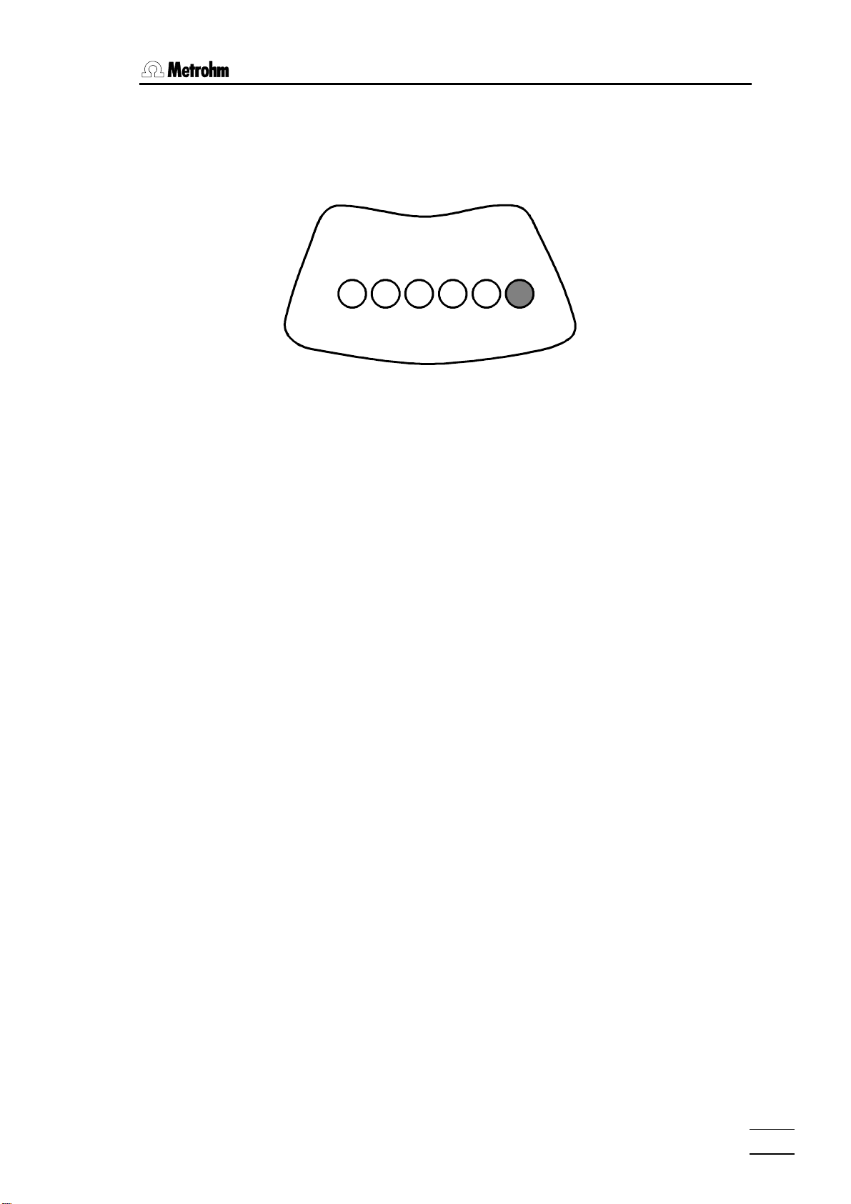
Magnet inserted
rack type
work position
In this
example the code is:
000110
base of rack
The rack type indicates an internal table of positions, in which the angles of
rotation of the beaker positions are defined. Metrohm racks use the following type name pattern:
MXX-Y (XX = number of sample beakers, Y = special code: 0 for 1-row,
1 for 2-row and 2 for 3-row standard racks)
e.g. M36-0 is a 1-row Metrohm standard rack with 36 sample positions.
The correct setting of the working position is very important. This is the lift
height which is to be used with the corresponding sample rack. It should be
selected so that the working head is standing in the optimal position. The
working position is given in mm (from the upper stop position).
A convenient way of determining this position is to set the required height
manually (normal state) with the <Ð> and <Ï> keys. This is done by
placing a sealed sample vessel on the oven and moving the lift carefully
downwards until the needle penetrates the septum and the lower rim of the
septum closure coincides with the upper rim of the oven opening.
The keyboard can then be used to open the configuration menu and the
current lift position in the display can be accepted in the menu entry 'work
position' with the <CLEAR> key.
774 Oven Sample Processor, Instructions for use
25
Page 32

3 Introduction
shift position
The sample rack can only be rotated when the lift is at or above the shift
position height.
The shift position should therefore be selected so that safe rotation of the
sample rack is always possible, i.e. it must be impossible to damage either
the needle or the rack when the rack is rotated. Please note that the conditioning vessel is slightly higher than the other sample vessels.
The value can also be entered manually or accepted automatically, as described for the work position - see above.
rinse position
The rinsing position defines a further height setting, which is used for conditioning, i.e. penetration into the conditioning vessel. See the exemplary
methods given in the 774 Tutorial.
The value can also be entered manually or accepted automatically, as described for the work position - see above.
special position
The special position can be used to define a further lift height.
No commands are linked with the defined lift positions. In principle they can
therefore be used with any lift heights which are to be stored.
special beakers (in sub-menu special positions)
Up to 8 special beaker positions can be defined for each sample rack; in a
normal method procedure these are not regarded as sample beakers. Special beakers can be deliberately selected at any time. For example, they can
be used as conditioning beakers. See the exemplary methods in the 774
Tutorial.
The special beakers 'Spec.1' to 'Spec.8' can each be allocated a beaker
position from 1 up to [number of sample positions]. Position 0 stands for
"not defined". Special beakers are preferably set at higher rack positions in
order to be able to start the series of samples at position 1. In the standard
rack for the 774 Oven Sample Processor position 36 is already defined as a
special position for the conditioning vessel and should not be altered.
3.1.4 Dosing units
dosing unit
max. rate
26
In order to be able to additionally automate the dosing-in of auxiliary solutions or aspiration from the measuring cell it is possible to connect up to 12
dosing instruments to the 774 Oven Sample Processor via 729 Dosimat interfaces. The 685 Dosimats and 700 Dosinos can be used for this.
The maximum dosing and filling rates as well as the tubing dimensions of
the inlet tubing can be defined for each dosing instrument.
Dosing unit for which the parameters are to be entered
(1–12, see page 65f).
This value represents the maximum permissible dosing and filling speed
(mL/min) of the dosing unit. Depending on the viscosity of the medium to
be dosed in, this value should be selected so that as rapid a dosing as
possible is selected; however, the buret must still be filled without any problems and free from any air bubbles. The max. rate is an absolute limit; it
cannot be exceeded even during manual dosing.
774 Oven Sample Processor, Instructions for use
Page 33

3.1 Configuration
tubing lengths and diameters
These values are only relevant for the 700 Dosino. As this has the ability to
prepare the complete tubing system automatically for dosing, i.e. to rinse
the tubings and fill them with dosing solution, the particular tubing lengths
and (inner) diameters must be entered. The necessary rinsing volumes are
then calculated automatically.
The settings for dosing units mentioned above must be carried out for all 4
ports of the 700 Dosino (inlets and outlets 1–4).
3.1.5 RS232 interface
Either a printer (for protocolling the instrument settings and methods) or a
PC for controlling the Oven Sample Processor can be connected to the
RS232 interface.
It is also possible to communicate with other Metrohm instruments (e.g.
Coulometer via Metrohm remote control language) and possibly instruments from other manufacturers via the interface.
The necessary transmission parameters which must be matched to those
of the instrument to be connected are:
baud rate, data bit, stop bit, parity and handshake.
For data communication with PCs, Metrohm instruments and instruments
from other manufacturers the parameter 'Send to: IBM' must be set. The
other parameters should remain set to the standard values or the settings
should be adapted to those of the corresponding peripheral unit.
Connection of a printer: see page 21.
Data reception can be switched on and off with 'control via RS: on'. If the
remote control is switched off then data can no longer be received, but reports can still be printed out.
774 Oven Sample Processor, Instructions for use
27
Page 34

3 Introduction
3.1.6 Lock keyboard functions
Particular areas of the operator dialog can be made inaccessible to untrained operators by locking individual dialog areas or keys. In this way the
accidental overwriting of a method or even the alteration of parameters can
be prevented.
The menu '>keyboard options' for the corresponding functions is opened
by holding down the <CONFIG> key when the Oven Sample Processor is
switched on. Alternatively this can be done by triggering a reset with
<CLEAR> and then pressing the <CONFIG> key within 0.4 seconds.
This menu can even be accessed when the complete keyboard has previously been locked.
The individual keyboard areas which can be locked are:
whole keyboard
In routine operation where only a single method is used it may be necessary to prevent manual manipulation. For this reason it is possible to lock
(almost) all keyboard keys. The <START>, <STOP> and <CLEAR/ RE-
SET> keys are always accessible so that starting and interrupting methods
is always possible. If the Oven Sample Processor is operated with PC software this may also be necessary. In this case it is possible to do without the
keyboard and to remove it completely.
'lock keyboard: on' locks all keyboard keys (exceptions: see above).
lock configuration
The basic configuration can be protected against overwriting. All settings of
the configuration menu are no longer accessible.
'lock configuration: on' locks the <CONFIG> key.
lock parameters
If operator-defined methods are normally used then it may be necessary to
ensure that the stored method parameters cannot be altered. The parameter menu can therefore be made inaccessible.
'lock parameters: on' locks the <PARAM>key.
lock method memory functions
Preventing the accidental deletion of stored methods makes sense. The deletion of methods should only be possible after deliberately switching off the
locking function.
'>user methods' + <ENTER> opens the submenu for locking method
memory functions.
'lock method recall: on' locks method loading.
'lock method store: on' locks method saving.
'lock method delete: on' locks method deletion.
28
774 Oven Sample Processor, Instructions for use
Page 35

lock display
3.1 Configuration
If the Oven Sample Processor is to be operated solely by external control
software (see above) then the display for manual operation can be
switched off.
'lock display: on' locks the display.
774 Oven Sample Processor, Instructions for use
29
Page 36

3 Introduction
3.2 Manual operation
As an introduction only those basic manual control functions which are
necessary for preparing the sample changer for processing a series of
samples are described here.
Only a few keys are required.
For further commands and details please refer to page 61ff and page 74ff.
Shift sample rack / position samples
The <Í> and <Î> keys can be used to rotate the sample rack one
position to the left (counterclockwise) or right (clockwise).
The MOVE function can be used to position a particular sample vessel on
the oven. Apart from the numerical rack position, <SELECT> can also be
used to enter the position defined as the current sample (SAMPLE command) or the special beaker 1 to 8.
Example:
MOVE : sample <ENTER>
MOVE : spec.1 <ENTER>
MOVE : 5 <ENTER>
Important:
For safety reasons it is only possible to rotate the rack when the lift is at or
above the shift position height.
The <Ï> and <Ð> keys move the lift upwards and downwards respectively. The lowest possible lift position is defined under the configuration
parameter 'max. lift way'.
The <HOME> key is used to return the lift to the resting position (0 mm),
i.e. to the upper stop position.
<END> moves the lift to the predefined working position (see pages 65
and 77).
The LIFT function can be used to move the lift to a particular position. As
well as the exact position in mm (0 –100 mm), a previously defined position can be selected with <SELECT> (rest pos = 0 mm, working, rinsing,
shift pos, special).
Example:
LIFT : work <ENTER>
LIFT : shift pos <ENTER>
LIFT : 50 mm <ENTER>
MOVE
8
Move lift
HOME
LIFT
9
END
30
774 Oven Sample Processor, Instructions for use
Page 37

3.2 Manual operation
Set sample position
SAMPLE
The SAMPLE function is used to set the current sample position. It defines
the first sample beaker for the following series of samples.
7
4
5
DOS
6
The FLOW function is used for switching the pump or inert gas solenoid
valve on and off. <SELECT> is used to select the parameters for this
command from the two possibilities. The first parameter of the command
defines whether the pump (i.e. air as gas flow) or the solenoid valve for
other gases is to be switched on. The current gas flow rate is shown directly in the display .
Example:
FLOW: pump : ON
FLOW: valve : OFF
<STOP> is used to switch off the pump (or valve) again, provided that
nothing else has been defined under 'Manual stop options', see page 74.
The HEATER function is used for controlling the oven temperature. The first
parameter of the command defines the oven temperature, the second
parameter sets the heating-up time, i.e. the time in which the defined temperature is to be reached. If the defined temperature is lower than the current oven temperature then the oven unit will be automatically cooled. The
current oven temperature is always shown in the display.
Example:
HEATER:init°C min (=heat up to initial temperature)
HEATER: 130°C 15 min
The DOS function is used to control the connected dosing instruments.
Both positive and negative volumes can be dosed.
Apart from entering the volume to be dosed, <SELECT> can be used to
select additional functions of the particular dosing instrument:
- Filling the cylinder (fill),
- Change dosing unit initialization (change),
- Prepare the tubing system (prepare),
- Empty the tubing system and the cylinder (empty),
- Eject the cylinder contents (eject),
- Adjust, i.e. remove the play between dosing piston and spindle before
aspiration or filling the cylinder (adjust),
- Compensate for the play between dosing piston and spindle before
dosing (level).
Pump / Valve
FLOW
Oven control
HEATER
Dosing units
(=heat to 130°C within 15 minutes)
774 Oven Sample Processor, Instructions for use
31
Page 38

3 Introduction
The first parameter of the DOS command represents the number of the
dosing instrument (1–12), the second parameter the function or volume to
be dosed.
Example:
DOS: 2 <ENTER> 4.51 ml <ENTER>
DOS: 2 <ENTER> <SELECT> ... fill <ENTER>
Interface monitoring
SCAN
1
Operate interfaces
CTRL
2
The SCAN function is used for monitoring the serial RS232 and the remote
interfaces. In this way it is possible to check the communication of the 774
Oven Sample Processor with other instruments. The interface can be selected with the <SELECT> key and must then be confirmed with <EN-
TER>.
If the Remote interface is selected then the logical condition of input lines
0…8 is displayed as a bit pattern (1=active, 0=inactive). If the RS232
interface is selected then the received character strings are shown.
Example:
SCN:Rm :00000001 (= e.g. Coulometer is 'ready')
SCN:RS $d
The CTRL function is used to operate the serial RS232 and remote interfaces. In this way it is possible to check the communication of the 774
Oven Sample Processor with other instruments. It is therefore possible to
transmit a remote command as a character string to a connected instrument via the RS232 interface or to individually activate or deactivate remote lines Output 0…13.
The interface can be selected with the <SELECT> key and must then be
confirmed with <ENTER>.
If the RS232 interface is selected then any character string can be entered;
this will be transmitted after confirmation with the <ENTER> key.
If the remote interface is selected then a 14-place bit pattern can be defined which then defines the required logical conditions of remote lines
0…14. (1=active, 0=inactive, * =do not alter current condition). The
<SELECT> key can be used to select predefined bit patterns to cover the
most frequently required tasks (see also page 98ff). Setting the lines (static
signals) is carried out after pressing the <ENTER> key.
Example:
SCN:RS $d (=status query of Coulometer)
CTL:Rm :************01 (=start Coulometer or Titrino)
CTL:Rm : START device1 (=start Coulometer or Titrino)
(= status query of Coulometer)
32
774 Oven Sample Processor, Instructions for use
Page 39

3.3 Methods and Sequences
3.3 Methods and Sequences
3.3.1 Designing a method
A method is made up of the following components:
• number of samples to be processed
• run sequences (start, sample and final sequences)
• Definition of the various instrument settings (report definitions, sample
changer settings, time-out settings, gas flow settings, dosing unit definitions, manual stop options)
For details about instrument settings please refer to page 67ff.
Sequences
A sequence is a series of commands which are carried out in the defined
order when a series of samples is being processed. Functions for controlling the oven temperature, gas flow, lift and for moving the turntable are
available. External instruments (titrators, Coulometers, Dosimats, etc.) can
be controlled by efficient commands. In a sequence the further settings for
the individual instrument components and dosing units (700 Dosino or
685 Dosimat) can also be defined or altered.
Processing a sample series is carried out in three phases. These are:
Start sequence: Command sequence which is carried out once at
the start of the series.
Sample sequence: Command sequence which is carried out for
each sample.
Final sequence: Command sequence which is carried out once at
the end of the series.
Course of a method
number
of samples
<START>
start sequence final sequence
774 Oven Sample Processor, Instructions for use
sample sequence
normal state
33
Page 40

3 Introduction
Sequences are created in the submenus '>start sequence', '>sample
sequence' and '>final sequence'; these can be accessed via the pa-
rameter menu (press <PARAM>).
A sequence is arranged in lines. If a command is entered a new line containing this command will be appended to the line which is currently shown.
The line number can be seen in the display. 99 lines are possible per sequence.
A line is deleted by pressing <DELETE>. The following lines move up one
position.
A new line can be inserted at a later date by using <INSERT>. This inserts
an empty line before the line which is currently shown. The following lines
move down one position.
The commands which are available as a second function on the numeric
block of the keyboard can also be used in a command sequence. These
are almost the same commands which are used for manual operation.
However, in a sequence these may possess other or further selection possibilities.
During the course of a method it is possible to alter all entries in the 'con-
figuration' and 'parameters' menus. With a few exceptions (see page 23ff)
these alterations directly affect the course of the method.
Care should be taken in making alterations to the method sequences. These
can be edited "live" (including inserting or deleting a command line); however, the TRACE and LEARN functions are not available. It is therefore not
possible to test out the edited function. This means that it is easy to produce
illogical or critical command sequences which create an error situation and
compel a sample series to be aborted.
3.3.2 LEARN mode and TRACE function
As when editing a method it is easiest to determine the parameters of a
command interactively, i.e. by manual operation, certain commands are
"adaptive". When editing a sequence the LEARN mode makes it possible to
carry out particular sample changer commands by manual operation. In
this way the resulting parameter (e.g. the lift position or the status of the input lines of the remote interface) can be included in the actual command
line. The LEARN function can be used repeatedly. If times or volumes are
"learned" then this means that the values will always be added together.
Procedure for creating methods:
• Enter a command or select an existing command line
• Press the <LEARN / HOLD> key
• the function starts, the "LEARN"-LED lights up
• press the <LEARN / HOLD> key
• function is stopped, the "LEARN"-LED blinks
• use the <ENTER> key to accept the value (or start the LEARN
function again)
• The "LEARN"-LED goes out, edit the next command line
34
774 Oven Sample Processor, Instructions for use
Page 41

3.3 Methods and Sequences
The LEARN function is available for the following commands:
Command Adaptive parameter Type of function
LIFT Lift position in mm absolute
WAIT pause time in seconds additive
DOS Dosing volume in mL additive
SCN Rm Status of the 8 remote lines "live" value
SCN RS Received character string "live" value
TRACE function
The "TRACE" function is a valuable aid for processing a complete sequence
or method, or excerpts, step-by-step for test purposes. Each command line
in a sequence can be carried out directly by pressing the <START> key.
When the action is finished the following command line is displayed.
"Tracing" can be used directly after the entry of a command line or at any
time after the parameter menu has been opened and a sequence has been
selected.
3.3.3 Process control
<START> is used to start a method from the normal state. If not interrupted manually and if no unexpected errors occur the sample series will be
processed properly and terminated with the final sequence. The sample
sequence is carried out several times according to the entry in 'No. of samples', starting with the sample beaker which has been defined as 'SAM-
PLE'.
If the sample series is interrupted with <STOP> the Oven Sample Processor immediately returns to the normal state. Unprocessed samples are not
taken into account; the final sequence is not carried out. If settings for this
occurrence have been entered under '>manual stop' then the corresponding actions or commands will be carried out via the interface in order to
stop the connected instruments as well or to carry out other actions.
The sample series can also be interrupted with <HOLD>. The command
which is currently active is immediately terminated. <START> can be used
to continue the method with the following command in the sequence which
is active. Connected peripheral units are not stopped with the <HOLD>
key. In the 'HOLD' condition the current oven temperature is maintained.
<CLEAR> interrupts a sample series when the currently active sequence
has ended (soft termination). The sample which is currently being processed will be processed to the end.
<QUIT> terminates the command currently being carried out and starts
the next command line of the sequence.
If errors occur during a sample series then a corresponding error mes-
sage will appear; this must be confirmed with <QUIT>. The sample
changer then goes to the HOLD status (see above). When the error has
been remedied <START> can be used to continue or, if necessary,
<STOP> can be used to terminate the sample series completely.
If the gas flow limits are exceeded or undercut this does not interrupt the
method sequence. The gas flow can be corrected manually with the gas
flow regulator.
774 Oven Sample Processor, Instructions for use
35
Page 42

3 Introduction
3.3.4 POWER-UP methods
When the 774 Oven Sample Processor is switched on the sample rack and
the guide head move to their rest positions. In order to condition the complete carrier gas tubing system when the instrument is switched on a
"POWER-UP" method can be used. This method is automatically started
when the instrument is switched on.
Create a method containing a command sequence which is to be carried
out when the 774 Oven Sample Processor is switched on and save this
method under the name "POWERUP" (see page 75).
In the 774 Oven Sample Processor tutorial you will find a list of the exemplary methods stored in
the instrument as standard together with comments about them.
36
774 Oven Sample Processor, Instructions for use
Page 43

4.1 Oven control
4 Oven control and gas flow
In addition to the essential sample changer features, such as rotating the
sample rack and raising and lowering the lift, the 774 Oven Sample Processor also has a controllable sample heating block and a gas supply device.
This means that it is extremely suitable for applications in which moisture or
solvent vapors are to be driven out of a sample at an increased temperature and transferred to a measuring cell in a stream of carrier gas. The 774
Oven Sample Processor together with the Metrohm Coulometer or a
Metrohm KF Titrator and the suitable KF measuring cell form the ideal analytical system for the determination of water in samples which cannot be titrated directly or only with great difficulty according to the conventional Karl
Fischer method.
4.1 Oven control
The oven heating block of the 774 Oven Sample Processor consists of a
solid aluminium block with a chromium steel jacket surrounding the sample
chamber. The sample chamber is intended for 22 mm x 38 mm sample vials and allows samples of up to approx. 8 g to be heated up to 250 °C in a
very short time. The heating rate is up to 15 °C/min, depending on the temperature range. The built-in fan quickly cools the oven down and supports
the accurate temperature control of the oven block.
The temperature control of the oven is functionally separate from the other
(sample changer) functions of the 774 Oven Sample Processor, i.e. the set
oven temperature remains constant (background control), even when other
functions or commands are carried out.
The required oven temperature can be set in three different ways:
• Initial temperature
tion menu of the 774 Oven Sample Processor. As soon as the instrument is switched on the temperature control is activated and the oven
heats up to the required (initial) temperature. The value of the initial temperature remains stored in the instrument and can be used by the manual HEATER function or the programmable HEATER command.
<CONFIG> key
Configuration
>oven settings
initial temperature 110°C
– an initial temperature can be set in the configura-
• Manual HEATER function – the oven temperature can be set manually to
any required value. When the <HEATER> key has been pressed the
required temperature and the duration of the heating-up phase can be
entered. If no heating-up time is entered then the full heating power will
be used to reach the required temperature as quickly as possible; this
temperature is then maintained.
<HEATER> key
HEATER: 110°C 10 min or
HEATER:init°C min
774 Oven Sample Processor, Instructions for use
37
Page 44

4 Oven control and gas flow
• Programmable HEATER command – the HEATER command can be
used as a part step in the processing sequence of a method. This
means that it is possible to alter the program-controlled oven temperature whenever this is necessary. If the HEATER command is used the
heating-up period can be freely selected so that it is possible to carefully
warm up a sensitive sample. Temperature profiles or ramps within a sequence can be followed by repeated use of the HEATER command.
This allows the realization of complex applications, e.g. the determination of surface moisture and the water of crystallization content of solid
samples in the same run.
initial temperature initial temperature
4.2 Gas flow
parameters
>sample sequence
1 HEATER: 110°C 10 min
…
10 HEATER: 180°C 15 min
…
15 HEATER:init°C min
T [°C]
180°C
HEATER: 180°C 15 min
110°C
HEATER: 110°C 10 min
10 min 15 min ? min
Method:
– controlled heat-up (moisture)
– controlled heat-up (water of crystallization)
– rapid cooling to initial temperature
HEATER:init°C min
t [min]
In order to drive out moisture quantitatively from a sample it is necessary to
remove the vapors formed on heating with a stream of gas. This stream of
gas is also used to lead the vapors into a reaction solution contained in a
measuring cell.
With thermally stable, unproblematic sample substances, such as oils, air
can be used as the carrier gas; this can be supplied by the pump built into
the tower of the 774 Oven Sample Processor. However, it is necessary to
dry the air with a desiccant such as molecular sieve before it can be used.
In the Oven Sample Processor tower the flow of air is led through a pressure regulator and a flowmeter. An excess pressure valve ensures a constant overpressure of approx. 60…80 mbar in the tubing system.
With thermally unstable samples or samples which are sensitive to air it is
recommended that nitrogen or helium is used as an inert carrier gas. As
these gases are available in gas cylinders or pressure lines they can be
connected directly to the tower of the Oven Sample Processor via the solenoid valve. A pressure reduction valve must be used to ensure that the gas
pressure is less than 1 bar. The required value can also be set here with
gas flow regulator.
38
774 Oven Sample Processor, Instructions for use
Page 45

4.2 Gas flow
Gas flow diagram:
air inlet
inert gas inlet
Gas flow
side
Air/N
left-hand
instrument
gas flow
control knob
Air/N2 in
solenoid
valve
to Drying flask
from Drying flas k
pressure contr ol
pump
flow meter
valve
tower
inlet filter
injection
needle
conveying tubing
outlet needle
sample
The gas flow can be set manually with the help of the gas flow regulator and
the flowmeter. The flow rate of the carrier gas is shown on the display in
mL/min or L/h so that it is easy to set the required gas flow with the rotary
knob of the gas flow regulator. A gas flow of 20 to 100 mL/min is required;
in
2
this depends on the determination method and moisture in the sample.
titration cell
Display:
******** counter 1/36
110°C 55 mL/min ready
(
press <DISPLAY>)
The gas flow is monitored automatically. A lower and an upper limit can be
defined for the gas flow; if these are undercut or exceeded an error message is displayed. It is recommended that the safety limits (min. flow and
max. flow) are not set too closely for gas flow monitoring. A range of approx. 30 mL/min should be set.
During needle penetration and removal the gas flow should be switched off
as large variations in gas pressure occur during these processes. This
avoids unnecessary error messages.
774 Oven Sample Processor, Instructions for use
or:
gas flow 55 mL/min
heater temp. 120°C
39
Page 46

4 Oven control and gas flow
4.3 KF Moisture determination
The 774 Oven Sample Processor is predestined for Karl Fischer moisture
determinations. The oven method is used for those samples in which the direct determination of the water content is either impossible or very difficult.
This applies for substances which either directly react with the Karl Fischer
reagents or only release their moisture very slowly into the reaction solution
because of their insolubility, e.g. plastic granulates or oils.
The principle of the oven method with the 774 Oven Sample Processor:
Preparation:
• The samples are weighed into sample vials and tightly sealed with a
PTFE-coated septum. The sample weights are entered on the Coulometer or KF Titrator.
• The sample vials are placed on the rack and the sample oven is heated
up.
• A sealed but empty sample vial is used as the conditioning vial and is
placed in the rack position intended for it.
Conditioning and blank determination
• The conditioning vial is moved to the oven and the lift is lowered to the
rinsing position. The needle penetrates the conditioning vial septum.
• The gas flow is now switched on in order to purge the complete tubing
system and to provide reproducible and constant conditions.
• The measuring cell is now conditioned with a Coulometer or KF Titrator
until the reaction medium is sufficiently dry.
• The gas flow is switched off and a blank sample is moved into the oven,
the gas flow is switched on again and a blank value determination is
carried in order to determine the influence of the surroundings during
the heating-up period. The moisture released during a constant heatingup period (similar to the sample heating-up period) or the moisture in
the empty sample vessel and the basic drift per unit of time can be determined separately.
• When the determination of the blank value has been completed the reaction medium is reconditioned.
40
774 Oven Sample Processor, Instructions for use
Page 47

4.3 KF Moisture determination
[µg H
water
[µg]
drift
2O/min]
vial humi dity
in µg
min. extraction time
blank
min. extraction time
total blank value
system drift
in µ g/min
The blank value is made up of the moisture
which adheres to the sample vial * and a system drift which is latently present and whose
cause can be found in a minimal residual moisture in the carrier gas and possibly leaks in the
tubing system.
*
The use of pre-dried sample vials has no significant advan-
t [min]
tages. On the contrary, this causes the reproducibility of
determination in terval
the results to be adversely affected.
The accompanying diagram shows the theoretical course of a sample determination with the
774 Oven Sample Processor. It is clear that, in
order to determine the amount of water correctly
sample
(dark gray area), the blank value must be subtracted from the total amount of moisture determined.
t [min]
determination in terval
Sample determination
• When the reaction medium has been conditioned fully the gas flow is interrupted, the sample moved to the oven and introduced into the oven
block with the help of the penetration needle.
• The gas flow is switched on again and the sample determination started
at the Coulometer or KF Titrator. Definition of an extraction time ensures
that a minimum determination time and therefore heating period will be
observed.
• The driven-off moisture is now transported to the reaction vessel by the
stream of gas. The transfer tube heating ensures that no moisture can
condense in the tubing.
• When the determination is finished the moisture content of the sample is
calculated taking the previously determined blank value into consideration.
• The gas flow is switched off again and the conditioning vessel again
move to the oven.
• When the needle has penetrated the conditioning vessel septum the gas
flow is switched on again and the reaction medium is conditioned.
• When conditioning has been carried out the next sample can be determined, see above.
Care must be taken that the septa are still airtight after penetration by the
hollow needle and that no moisture can escape. The septum of the conditioning vessel is particularly at risk as it is penetrated many times during the
sample series.
774 Oven Sample Processor, Instructions for use
41
Page 48

4 Oven control and gas flow
Evaluation
The water determination as such can be carried out with a Coulometer or
Karl Fischer titrator.
If a Coulometer is used care must be taken that gas flow and oven temperature are selected so that the sample moisture is not driven off too
quickly. Otherwise a moisture excess may not be absorbed by the solvent
in the Coulometer cell, but condense in the upper part of the cell or even be
blown out of the cell. Moisture depots lead significant increase of the
measured value drift. Reduced reproducibility of results may occur.
Please note: The measured value of the Coulometer must not exceed
100 mV.
42
774 Oven Sample Processor, Instructions for use
Page 49

5.1 The display
5 Detailed description
5.1 The display
The display consists of two lines, each having 24 characters.
The first line serves as a title line in which the current method and the sample counter reading are displayed. In edit mode the menu title is shown.
The second line serves as a status line which displays specific activities
depending on the operating state. In edit mode it serves as an entry line.
Normal state
method name Î
oven temperatur Î
Ï gas flow
Method processing
sample counter Ð
******** counter 1/36
110°C 55 mL/min ready
Í instrument status
running sequence Î
Mesured values
Edit mode
menu line or command Î
******** counter 2/36
START 03 WAIT 11 s
Í parameter
Ï current command with line number
gas flow 55 mL/min
oven temp. 110°C
Using key <SELECT/DISPLAY>, you can switch back to
measured value display at any time
Ð Menu title
>sample sequence
1 MOVE 1 : sample
Í second parameter
Ï first parameter
774 Oven Sample Processor, Instructions for use
43
Page 50

5 Detailed description
5.2 The keyboard
774 SC Controller
HEATER FAN VALVE
CONFIG PARAM
HOME END
USER
METHOD
SAMPL E8MOVE
7
FLOW
PUMP
HEATER
4 5
INSE RT
DELETE
DISPLAY
SELEC T
QUIT ENTE R
CLEAR
RESET
SCAN
1
DEF
0
LEARN
PRINT
CTRL
2
.
Met rohm
<
LIFT
9
DOS
6
WAIT
3
RACK
*
>
HOLD
6.2142.030
STOP START
Most of the keys have two functions according to whether the sample
changer is in the normal state or in edit mode.
The uppermost row contains the (<CONFIG>, <PARAM>, <USER
METHOD>) keys which make the menus accessible. Here with the help of
the keys on the left side of the keyboard, you can navigate and change parameters. For the latter, the numerical keypad on the right half of the keyboard is available. Except for the menu “User Method” the entries under
these selection menus can be altered while a method is in process and for
the most part, have an immediate effect on the procedure which is running.
The lowermost row of keys (<HOLD>, <STOP>, <START>) are used
for the direct control of method processing.
44
774 Oven Sample Processor, Instructions for use
Page 51

5.2 The keyboard
5.2.1 Individual key functions
Key Normal state Editing
CONFIG
PARAM
Opens the configuration Menu
• The <Config> key opens the
selection menu for the configuration of the sample
changer.
• The settings in the Configuration Menu remain constant until they are changed or the
working memory (RAM) is reinitialized.
Open the parameter menu
• The <Param> key opens the
selection menu for the
changer and dosing settings.
• All settings that are set in the
Parameter Menu belong to a
method and will be saved with
the method. These parameters are method-specific.
Select configuration settings
• When the Configuration Menu
is open, pressing the
<CONFIG> key displays the
next menu line.
• After the last line is displayed,
the first one follows.
• <Quit> exits the menu.
Select method parameters
• When the Parameter Menu is
open, pressing the
<PARAM> key displays the
next menu line.
• After the last line is displayed,
the first one follows.
• <Quit> exits the menu.
• The settings in the Parameter
Menu also apply to Manual
mode.
USER
METHOD
HOME
Open the user method menu
• The <User Method> key
opens the selection menu for
the loading, saving and deletion of user-defined methods.
Bring lift to zero-position
• The <Home> key runs the lift
of the active tower to the zeroposition (0 mm), i.e. to the
upper stop.
Select method functions
• When the User Method Menu
is open, pressing the <USER
METHOD> key displays the
next menu line.
• After the last line is displayed,
the first one follows.
• <QUIT> exits the menu.
Select the first line of a menu
• With the <Home> key, the
first line in a menu or a sequence can be accessed.
• Any data that has been altered
in a menu or command line is
not carried over. See
<ENTER> key.
774 Oven Sample Processor, Instructions for use
45
Page 52

5 Detailed description
Key Normal state Editing
END
Lift in work position
• The <End> key runs the lift of
the active tower into the work
position.
• The work position is defined
separately for every sample
rack in the Configuration
Menu under “>rack defini-
tions”.
Run lift upwards
• Run lift of the sample changer
upwards using the <Ï> key.
The lift movement is executed
as long as the key remains
pressed.
• The speed of the lift move-
ment can be adjusted separately for each tower in the Parameter Menu.
Run lift downwards
Select the last line of a menu
• With the <END> key, the last
line in a menu or a sequence
can be accessed.
• Any data that has been altered
in a menu or command line is
not carried over. See
<ENTER> key.
Select previous menu line
• In a Select Menu or a se-
quence the <Ï> key ac-
cesses the previous line.
• Any data which has been al-
tered in a menu or command
line is not carried over. See
<ENTER> key.
Select next menu line
• Run lift of the sample changer
downwards. The lift movement
is executed as long as the key
remains pressed.
• The speed of the lift move-
ment can be adjusted separately for each tower in the Parameter Menu or with the
<DEF> key.
Turn rack left
• The <Í> key turns the
sample rack one position to
the left, i.e. in the counterclockwise direction. The next
highest beaker position is
placed under the lift.
• The turning speed of the rack
can be defined in the Parameter Menu or with the <DEF>
key.
• The rotation of the rack can
only be carried out when the
lift is at or above the shift position.
• In a Select Menu or a se-
quence the <Ð> key ac-
cesses the next line.
• Any altered data in a menu or
command line is not carried
over. See <ENTER> key.
Move the cursor one column to
the left
• With the <Í> key the cursor
is moved one column to the left
in an edit line with two parameters.
• Any altered data will not be
carried over during this action.
See <ENTER> key.
46
774 Oven Sample Processor, Instructions for use
Page 53

5.2 The keyboard
Key Normal state Editing
INSERT
Turn rack right
Move the cursor one column to
the right
• The <Î> key turns the sam-
ple rack one position to the
right, i.e. in the clockwise direction. The next lowest
beaker position is placed under the lift.
• With the <Î> key the cursor
is moved one column to the
right in an editing line with two
parameters.
• Any data which has been altered will not be carried over
• The turning speed of the rack
can be defined in the Parameter Menu or with the <DEF>
key.
during this action. See
<ENTER> key
• The rotation of the rack can
only be carried out when the
lift is at or above the turning
position
Add a command line to a sequence
• Adds a new command line
before the current line in a
sequence. The “NOP” command (no operation) automatically occupies this line and has
no function.
• The lines following this line are
shifted one line downwards.
DELETE
Delete a command line in a
sequence
• Deletes the current line in a
sequence
• The lines which follow shift
upwards by one line.
774 Oven Sample Processor, Instructions for use
47
Page 54

5 Detailed description
Key Normal state Editing
DISPLAY
SELECT
RESET
CLEAR
Selection of the display mode
• The display can be switched
over to display of the measured values (oven temperature
and gas flow) with key
<DISPLAY / SELECT>.
Pressing this key again
switches back to the previous
display mode. This can be
done in the basic state and
whilst the method is running.
Select parameter
• With the <Select> key given
data values can be selected for
a particular parameter in manual operation.
• With every repeated keystroke
the next value that can be selected is displayed. The last
value is followed again by the
first.
• The data is accepted with
<ENTER>.
Initialization of the changer
and the dosing units
• The <RESET> key serves to
initialize the changer and the
dosing units.
• A method in the working
memory remains unchanged.
The sample rack and the lifts
return to their initial positions
in this case. A 'release' command will be executed when
Deleting parameters, setting
the default values
• The <CLEAR> key sets the
initial (default) value given for a
parameter.
Delete last character
• In text edit mode the last character will be deleted with
<CLEAR> (Backspace).
Dosinos are connected.
Interruption of a method after
the current sequence
• During processing of a
method, the sample series
can be aborted with
<CLEAR> so that the sample currently being processed
is processed to completion.
The end sequence is not executed in this case.
48
774 Oven Sample Processor, Instructions for use
Page 55

5.2 The keyboard
Key
QUIT
Normal state Editing
Abort current command
• Whilst a method is running,
you can abort a command
currently running with the
<QUIT> key and continue
with the next command. This is
practical if a programmed
waiting time is to be shortened
or, in the case of a SCAN
command, the expected signal
cannot be recorded.
Abort Entry
• The <QUIT> key interrupts
the entry of a parameter. The
original entry is reset.
• The next highest menu level or
the normal state is selected.
• Any changed data of a menu
or command line is not
adopted in this case. This is
signalled by a beep. See
<ENTER> key.
Quit error messages
• <QUIT> acknowledges error
• <QUIT> acknowledges error
messages.
messages. During method
processing the sample
changer goes into the 'HOLD'
state after this. After this, you
can continue with the next
command line with
<START> or stop the sequence with <STOP>
• The command at which the
error message occurred is always continued (in Manual
mode).
Accept data, next line
ENTE R
• The <ENTER> key accepts
the value entered and selects
the next menu line.
• A modification of data or parameters must always
be
confirmed by <ENTER>, otherwise the change will not be
accepted.
• If a change in a parameter is
not confirmed by <ENTER>
and another menu line is accessed, the previous value will
be reinstated. This is indicated
by an acoustic signal.
774 Oven Sample Processor, Instructions for use
49
Page 56

5 Detailed description
Key Normal state Editing
SAMPLE
7
MOVE
8
Set sample position
• The <SAMPLE> key serves
to set the current sample position.
• When starting a method, this
position is assumed to have
the first sample of a series.
• If the current sample position
is not manually set before the
start of a sample series, rack
position 1 is always started
first.
Position vial
• Turn the sample rack to position the described vial under
the lift. In addition to the predefined sample vials, the eight
rack-specific special positions
available can be placed. Absolute positions can also be
chosen.
• Turning direction and speed
can be altered in the Parameter Menu or with the <DEF>
key.
Numerical entry ('7')
or
Set sample position
• In a start sequence the
SAMPLE command serves to
define the first sample of a
sample series.
• If no SAMPLE definition is
made in any sequence, the
manually set rack position is
assumed to be the first sample.
Numerical entry ('8')
or
Position vial
• Turning the sample rack to
position the described vial under the current lift. In addition
to the predefined sample vials,
the 8 rack specific special positions available can also be
placed. Absolute positions can
also be chosen.
• Turning direction and speed
can be altered in the Parameter
Menu or with the <DEF> key.
50
LIFT
9
Positioning the lift
• Raises or lowers the lift to a
predefined position. These
positions (shift position, work
position, …) can be defined in
the Configuration Menu as
rack-specific.
• An absolute lift position in mm
can also be given.
Numerical Entry ('9')
or
Lift positioning
• The lift can be run to the predefined positions (work position,
shift position, …) in a sequence.
• An absolute lift position in mm
can also be entered.
774 Oven Sample Processor, Instructions for use
Page 57

5.2 The keyboard
Key Normal state Editing
FLOW
4
HEATER
5
Activating/deactivating gas
flow
• Key <FLOW> is used to
activate resp. deactivate the
air pump or the solenoid valve
(Air/N
in).
2
• The first parameter serves to
select pump or valve. The
second parameter defines
status 'On/Off'. The function
must be confirmed with
<ENTER>.
Oven control
• Key <HEATER> serves to
set the current oven temperature.
• The first parameter defines the
oven temperature. With the
second parameter, it is possible to achieve a slow, timecontrolled heating-up process
to the set target temperature.
You can set a time interval
within which the target temperature should be reached.
The function must be confirmed with <ENTER>.
Numeric entry ('4')
or
activate/deactivate gas flow
• The FLOW command serves to
activate resp. deactivate the air
pump or the solenoid valve
(Air/N
in).
2
• The first parameter serves to
select pump or valve. The second parameter defines status
'On/Off'.
Numeric entry ('5')
or
oven control
• The first parameter defines the
oven temperature (target temperature).
• Using the second parameter, it
is possible to program temperature ramps or (by combining several HEATER commands) entire temperature profiles. The heat-up interval defines the period within which
the set target temperature
should be reached.
DOS
6
774 Oven Sample Processor, Instructions for use
Dosing control
• The <DOS> key serves for
• The first parameter is for the
• In addition to dosing volume
• The dosing and filling speed
the control of Dosimats and
Dosinos. These are controlled
via the "External Bus" connector.
selection of the dosing unit.
The second parameter represents the function.
and the fill command, the
functions specific to the Dosino -’prepare’, ‘release,
‘empty’ and 'release'- can also
be executed.
can be set in the parameter
menu or with the <DEF> key.
Numerical entry ('6')
or
Dosing control
• In a sequence you can not only
add a certain volume under
process control, it is also possible to initiate the burette filling
with Dosimats or initiate the
designated functions with Dosinos as there are: filling, emptying, preparation or release of
the exchange unit.
51
Page 58

5 Detailed description
Key Normal state Editing
SCAN
1
Display input signals
• Display of the incoming signal
or data on the remote or RS
interface. This function serves
to control the data communication or states of connected
instruments.
• The first parameter represents
the interface selection. The
signals for data being received at that moment are
displayed as the second parameter.
• If the parallel remote interface
(Rm) is selected, the signal
states of the incoming remote
lines are displayed in binary
form. (1=line active, 0=line
inactive). Further details relating to this are on page 78ff.
• If the serial RS 232 interface
(RS) is selected, the character string being received, is
displayed line by line (14
characters). Details relating to
this are on page 96ff.
Numerical entry
or
Scan input signals
• In a sequence the SCAN
command causes method
processing to stop until the
predefined bit pattern (with the
remote interface) or the given
character string (with the RS
232 interface) is received.
• Predefined bit patterns are
available for the remote interface and can be selected via
simple short-names (for ex.
“ready1” or “end1”).
• Character strings consisting of
14 ASCII characters may be
defined with the
RS 232 interface. Use text edit
mode.
CTRL
2
Interface control
• Controlling of external instruments via the remote and RS
232 interface. This function is
used for data communication
with or control of connected
instruments.
• The first parameter stands for
the selection of the interface.
The second parameter defines
the state of the remote output
lines or data to be transmitted
via RS 232 interface.
Parameters with remote interface selected
• Bit pattern with 14 digits (0, 1
or *) for the 14 output lines or
predefined patterns accessible by the <SELECT> key (for
ex. "START device1", "STOP
instr.1" etc.).
Numerical entry
or
Interface control
• Setting the 14 signal lines of
the remote interface or sending
a character string via the RS
232 interface to control instruments connected.
• Predefined bit patterns are
available for the remote interface and can be selected via
simple short-names (for ex.
“START instr.1” or "STOP device2").
• Character strings consisting of
14 ASCII characters may be
defined with the RS 232 interface. Use text edit mode.
52
774 Oven Sample Processor, Instructions for use
Page 59

5.2 The keyboard
Key Normal state Editing
WAIT
Parameters for the RS 232
interface
• Character string with up to 14
alphanumerical characters.
Default value: “&M;$G”, may
be set with <CLEAR>. Most
Metrohm instruments can be
controlled with such remote
control commands, see pages
101ff.
3
DEF
0
Redefine various instrument
settings
• This function serves to temporarily change various settings.
Changes which are done in
this way are not integrated in
the method and are ignored
during processing of a
method.
• By repeatedly pressing the
<DEF> key the various settings can be selected. In order to change an entry the
function must first be confirmed with <ENTER> .
• The new settings take effect
immediately after confirmation
of the change by <ENTER>.
Numerical entry ('3')
or
Define waiting time
• Waiting for a certain time interval to elapse.
Numerical entry
or
Redefine various instrument
settings
• The DEF commands that are
available during manual operation are also programmable in
a sequence.
• This makes it possible to
change various instrument parameters under process control
during execution of a running
sequence.
774 Oven Sample Processor, Instructions for use
53
Page 60

5 Detailed description
Key Normal state and editing
DEF
0
DOSRATE
DEF
0
FILLRATE
DEF
0
LIFTRATE
• DEF commands are valid for manual operation as well as for the
programmed processing of a method.
• The individual DEF commands are listed below.
Change dosing rate
• The dosing rate may be individually set for every dosing drive (Dosimat or Dosino).
• Syntax: DOSRATE [Dosing unit] [Dosing rate]
Change filling rate
• The filling rate may be set individually for every dosing drive (Dosimat oder Dosino).
• Syntax: FILLRATE [Dosing unit] [Filling speed]
Change lift speed
• The lift speed can be set at will.
• Syntax: LIFTRATE [Tower] [Lift speed]
54
774 Oven Sample Processor, Instructions for use
Page 61

5.2 The keyboard
Key Normal state and Editing
DEF
0
SHIFTRATE
DEF
0
DRIVE.PORT
Change turning speed and direction
• In addition to giving the turning speed of the sample rack in angular
degrees/sec., the turning direction can also be indicated with the
first parameter.
• Turning direction "+" causes the sample beakers to be processed
in the counterclockwise direction, i.e. in ascending order. Turning
direction "–" indicates in the clockwise direction, i.e. in descending
order. The beaker positions are numbered on every sample rack
and easily visible.
• With turning direction “auto” the sample changer independently
chooses the shortest possible path for placing a vial under a particular lift. The turning direction is automatically chosen.
• Syntax: SHIFTRATE [Turning direction] [Turning speed]
Change Dosino port assignments
• The ports for each of the 12 Dosinos which can be connected may
be functionally redefined. Each port can therefore be used as dosing outlet or filling inlet, etc.
• The dosing drive must be given left of the dot of the first parameter
and after the dot, the respective port must be indicated.
• For the second parameter you can choose between the functions:
Dosing (Dos), Filling (Fill), Rinsing (Rinse), Empty (Empty) or Prepare (Prep).
• Syntax: DRIVE.PORT [Dosing drive.Port] [Function]
774 Oven Sample Processor, Instructions for use
55
Page 62

5 Detailed description
Key Normal state Editing
PRINT
RACK
*
<
.
>
-
Print report
• The <PRINT> key serves for
the manual printout of reports.
• The choice of printer type and
the parameters of the RS232
interface must be done in the
Configuration Menu unter
“>RS232 Settings”.
Initialise sample rack
• The changer can be initialised
with key <RACK>. The connected peripherals (e.g. Dosimats or Dosinos) are not affected by this.
• Once a method has been
loaded, it is retained. Sample
rack and lift are moved to initial position and automatic
rack detection is performed.
The rack can be removed in
the basic position.
Text entry
• In a menu or sequence line in
which entry of text is required,
(for ex. method name), text edit
mode is activated with "<".
• Existing text is deleted in this
event and the text cursor is set
on the left margin of the text
field.
• "<" serves also for shifting the
chain of characters to chose
from, i.e. the text cursor is
shifted one place to the left for
each instance. See page 60.
Text entry
• In a menu or sequence line in
which entry of text is required,
(for ex. method name), text edit
mode is activated with ">" .
• Existing text remains in this
event and the text cursor is set
at the end of the existing character string.
• ">" serves also for shifting the
chain of characters to chose
from, ie. the text cursor is
shifted one place to the right
for each instance. See page
60f.
56
774 Oven Sample Processor, Instructions for use
Page 63

5.2 The keyboard
Key Normal state Editing
START
STOP
Start a Method
• The <START> key starts a
method. Starting is only possible when the 774 Oven
Sample Processor is in the
normal state, i.e. when ‘ready’
is shown in the display.
• When starting a sample series, the sample counter is set
to 0.
Trace function
• During editing of a sequence,
the command defined in the
command line can be directly
executed with the <START>
key.
• A sequence can therefore be
tested from start to finish (or in
parts) in single steps ("tracing").
• When <START> is pressed
after an interruption
(<HOLD>), the sequence is
continued with the next command line.
Stop process and peripheral
instruments
• The <STOP> key terminates
a method.
• Any peripheral instruments
Stop editing
• <STOP> causes the editing
to abort and the instrument to
return to the normal state. (exception: Process sequences)
that are connected (Titrinos,
etc.) are not automatically
stopped. In ">manual stop
options", a submenu of the
Parameter Menu, you can
specify what signal or data is
to be transmitted via the interface involved (remote or
RS232) during manual activation of the <STOP> key. The
connected instrument can be
halted or if necessary, initialized (see page 74). In addition, you can define whether
the oven heater and the pump
(resp. the solenoid valve) are
to be switched off or not.
• During a manual halt of a
sample series with <STOP>,
the end sequence of the
method will not be executed.
• The manual stop options are
also effective in the normal
state.
774 Oven Sample Processor, Instructions for use
57
Page 64

5 Detailed description
Key Normal state Editing
LEARN
HOL D
QUIT
Interrupt Process
• The <HOLD> key interrupts
the processing of a method.
However connected peripheral instruments (Titrinos, etc)
are not halted. Only method
processing is interrupted.
• In the “HOLD" state a method
can be completely halted with
<STOP> or continued with
the next command in line by
pressing <START>.
• After quitting an error message during method processing the changer automatically
goes into the <HOLD> state.
Switch on LEARN mode
• The <LEARN> key serves to
start the Learn mode. This
mode is provided for easier
editing of process sequences.
It allows direct acceptance of a
parameter value that has been
set by manual control. LEARN
mode is available for the following commands:
LIFT, DOS, SCN, WAIT
• See page 34 also.
Quitting error message
• With the <QUIT> key error
messages can be acknowledged. Before acknowledging error messages, the cause
should be remedied.
• The command during which
the error message occurs will
nevertheless be carried out
(during manual operation).
Interrupt, select next highest
menu level
• With the <Quit> key the active
(sub)menu or a menu or command line is exited. The next
highest menu level or the basic
state is selected.
• Any data from a menu or
command line which has been
changed will not be taken over
in this case. This will be sig-
• If an error occurs during
naled by an acoustic signal.
method processing the error
message is acknowledged by
pressing the <QUIT> key
and the method is interrupted
(HOLD state). Afterwards
<START> can be used to
continue with the following
command line or <STOP>
will halt processing.
58
lnterrupt processing of current
command line
• During the processing of a
method <QUIT> stops a run-
ning command and continues
with the next command. This
is useful when a programmed
waiting time is to be shortened
or when the expected signal
cannot be received during a
SCAN command.
774 Oven Sample Processor, Instructions for use
Page 65

5.2 The keyboard
5.2.2 Data entry
Edit line
In a menu line or a sequence one or two parameters respectively can be
entered. A blinking block cursor indicates where a parameter can be entered.
>changer settings
shift rate ¦ 20
Ï Ï Ï
menu item cursor parameter
>sample sequence
08 FLOW: ¦ pump : on
Ï Ï Ï
command first parameter, second parameter
The cursor keys, <Î> and <Í>, can be used to switch between the parameters. Pressing <ENTER> shifts the cursor automatically to the right,
pressing <QUIT> correspondingly to the left.
Í title line
Í edit line
Í title line
Í edit line
<Select> Choices (Roll-up selection)
DISPLAY
SELECT
Data can usually be entered directly via the numerical keypad block on the
keyboard. Pressing <SELECT> at entries which are specially identified
by a colon displays a preset selection of data. This selection is cyclic,
structured like a revolving drum.
Example:
>RS232 settings
character set: IBM
<SELECT>
IBM
HP
Epson
Seiko
Citizen
<ENTER>
>RS232 settings
character set: Epson
774 Oven Sample Processor, Instructions for use
59
Page 66

5 Detailed description
5.2.3 Text Entry
The text editor can be used when text entry is provided.
Numbers can be entered directly via the keyboard.
PRINT
.
Character selection
<
RACK
-
*
The keys "<" or ">" open the text editor. With "<" an existing character
>
string is deleted and the text cursor is set to the left margin of the edit line.
With ">" an existing character string remains and the text cursor is set on
the last character of the existing text.
A character chain is displayed that is composed of all the characters in
alphabetical order that can be entered. The blinking character is the currently selected one (text cursor).
The keys "<" and ">" move the character chain composed of all possible
characters (capital and small letters, numbers and special characters, in alphabetical order) in the desired direction underneath the text cursor. Pressing these keys once has the effect that the character chain is shifted one
position left or right. The character chain can be shifted quickly by pressing
the keys longer.
Confirmation of the character selection
ENTE R
RESET
CLEAR
QUIT
The <ENTER> key causes the character that is currently positioned at
the text cursor to be appended to the existing text. When the entire width
of the edit line is filled, text edit mode is left and the text is accepted with
<ENTER>.
Delete character
The <CLEAR> key deletes the last character of the existing text line. The
text cursor automatically shifts one character to the left.
Exit text entry
With <Quit> text edit mode is exited. The text line displayed can be accepted with <ENTER> or rejected by pressing <QUIT> a second time.
60
774 Oven Sample Processor, Instructions for use
Page 67

5.2 The keyboard
Scheme:
>store method
method: ********
"<" or ">"
blinking text cursor
>store method
█
method:
ABCDEFGHIJ...abcd...1234...*%&/()=...
<ENTER>
>store method
method:
█
DEFGHIJ...abcd...1234...*%&/()=...
CC
<QUIT>
>store method
method: Chloride
<ENTER>
blinking text cursor
"<" or ">"
...<ENTER>...
<QUIT>
character chain
2x ">"
reject
An entire text line can be entered in this way, for example, for the naming of
a method. Text editing can be ended with <QUIT>. The text line will be
displayed in its entirety and can be accepted with <ENTER> or rejected
with <QUIT>.
774 Oven Sample Processor, Instructions for use
accept
61
Page 68

5 Detailed description
5.3 Menu organization
CONFIG
normal state
Example :
Configuration menu
configuration
>auxiliaries
configuration
>rack definitions
configuration
>dosing units
configuration
>RS232 settings
<ENTER>
<QUIT>
<QUIT>
<HOME>
<END>
<Ï>
<Ð>
>auxiliaries
dialog: english
>rack definitions
rack number 0
>dosing units
dosing unit 1
>RS232 settings
baud rate: 9600
>RS232 settings
data bit: 8
>RS232 settings
stop bit: 1
>RS232 settings
parity: none
>RS232 settings
Handshake: HWs
>RS232 settings
character set: IBM
>RS232 settings
RS control: off
<HOME>
<END>
<Ï>
<ENTER>
<Ð>
The <CONFIG> key opens the menu where the most important settings
of the instrument are grouped in submenus according to topic and may
be altered. In the first line of the display the description of the active
submenu is always displayed. Navigating within the menus is accomplished with the cursor keys;
<HOME> and <END> jump to the
first or last menu line respectively.
<QUIT> exits the active menu, opens the next highest menu level or
returns the changer to normal state.
<ENTER> either opens a submenu
or confirms data entry at the lowermost menu level. <CONFIG> can
be used instead of <Ð>.
62
774 Oven Sample Processor, Instructions for use
Page 69

5.3 Menu organization
t
t
CONFIG
5.3.1 Configuration
Main Menu:
configuration
>auxiliaries
configuration
>oven settings
configuration
>rack definitions
configuration
>dosing units
configuration
>RS232 settings
configuration
>auxiliaries
>auxiliaries
dialog: english
english, deutsch,
français, español
>auxiliaries
display contrast 3
0…3…7
>auxiliaries
beeper: ON
ON,OFF
>auxiliaries
device label ********
8 ASCII characters
>auxiliaries
program 5.774.0010
read only
The following three entries become effective after a RESET or switching the
changer on again.
>auxiliaries
max. lift way 90 mm
0…90…100 mm
This setting of the max. lift path is important as regards safety. Correctly en-
tering this value can prevent the puncture needle breaking off since the lift
cannot be moved lower than as far as the specified position.
<QUIT>
<QUIT>
to access nex
to access nex
higher level
higher level
use
use
Open submenu with <ENTER>
Use <Ï > or <Ð> to move up or down one menu item
Use <HOME> or <END> to move to first or last menu
item respectively
Return to normal state with <QUIT>
Basic Settings Submenu
Open the submenu with <ENTER>
Choice of dialog language
Setting display contrast
0 = no contrast
7 = large contrast
Turn acoustic warning signal on or off
Instrument label
Program version
Max. stroke path for lift
774 Oven Sample Processor, Instructions for use
63
Page 70

5 Detailed description
t
>auxiliaries
beaker sensor: ON
ON,OFF
Activate or deactivate beaker sensor
configuration
>oven settings
Submenu of oven settings
Open submenu with <ENTER>
Use
<QUIT>
to access nex
higher level
>oven settings
initial temp.: OFF °C
OFF, 50…250 °C OFF = Do not switch on oven heater
>oven settings
max.temperature 275 °C
50…275 °C
Setting the initial temperature of the
oven after switching on
Maximum possible temperature
(overheating safeguard)
>oven settings
temp.correction 0 °C
-10…0…10 °C
Correction value for heater control
configuration
>rack definitions
Submenu for the definition of the individual racks
Open the submenu with <ENTER>
>rack definitions
rack number 1
1…16
Number of the rack
The number of the rack in position is automatically displayed here. If the configuration of another rack must be changed, its rack number must be entered
and confirmed with <ENTER>. The rack number will be shown in the first
menu line for the subsequent entries.
>rack definitions 1
code 000001
6 Bits
Identification code of the rack
The rack code must be unique and can only occur once in the instrument.
>rack definitions 1
type : M36-0
M36-0…
Type description of the rack
See p. 88ff.
<SELECT> enables the choice of Metrohm-specific and self-defined rack
types.
64
774 Oven Sample Processor, Instructions for use
Page 71

5.3 Menu organization
mit
t
Use
<QUIT>
<QUIT>
to access nex
zur nächst-
höheren Ebene
higher level
configuration
>dosing units
>rack definitions 1
work position 0 mm
Working position of the lift (in mm from
the upper stop)
0…100 mm The working position is used for
sample determinations
Pressing <CLEAR> directly accepts the current lift position.
>rack definitions 1
rinse position 0 mm
Rinsing position of the lift (in mm from
the upper stop)
0…100 mm The rinsing position is used for
the conditioning vessel
Pressing <CLEAR> directly accepts the current lift position.
>rack definitions 1
shift position 0 mm
0…20 mm
Shifting position of the lift (in mm from
the upper stop)
Pressing <CLEAR> directly accepts the current lift position.
>rack definitions 1
spezial position 0 mm
0…100 mm
Special position of the lift (in mm from
the upper stop)
Pressing <CLEAR> directly accepts the current lift position.
>rack definitions 1
>>special positions
Special positions submenu
Open with <ENTER>
Position of special beaker 1
0…number of positions
>>special positions
special beaker 1 36
Position of special beaker 2
>>special positions
special beaker 2 0
0…Number of positions
etc. up to special beaker 8
Up to 8 special beaker positions can be defined. More information about
racks and special beakers is found on page 87ff.
Submenu for dosing unit settings
Open the submenu with <ENTER>
>dosing units
dosing unit 1
1…12
Select the dosing unit
(700 Dosino or 685 Dosimat)
The address of the dosing unit (see p. 19) must be confirmed with <ENTER>.
This will then be displayed in the first menu line.
774 Oven Sample Processor, Instructions for use
65
Page 72

5 Detailed description
n
t
n
t
use
<QUIT>
to access the
ext highes
level
Configuration
>RS232 settings
use
<QUIT>
to access the
ext highes
level
>dosing units 1
max. rate 1 160 ml/min
0.01…160 ml/min
Max. dosing speed (depends on burette size)
>dosing units 1
tube length 1 1000 mm
0, 1000, 30000 mm
Length of the tubing on Dosino port 1
>dosing units 1
tube diameter 1 2 mm
0.1…2.0…20 mm
Diameter of the tubing on Dosino port
1
>dosing units 1
max. rate 2 160 ml/min
0.01…160 ml/min
Max. dosing speed (dependends on
burette size)
>dosing units 1
...........................until Port 4
Enter the tubing diameter for all four
ports of a Dosino
Only the dosing speed is relevant for the 685 Dosimat; the other parameters
are ignored.
Submenu for the serial interface parameters
Open the submenu with <ENTER>
>RS232 settings
Baud Rate: 9600
300,600,
1200,2400,
4800,9600
Transmission speed in baud
>RS232 settings
data bit: 8
7,8
Number of data bits
>RS232 settings
stop bit: 1
1,2
Number of stop bits
>RS232 settings
parity: none
even, odd, none
Parity selection
>RS232 settings
handshake: HWs
HWs,HWfull,
SWchar,SWline,
none
Handshake selection
>RS232 settings
character set: IBM
IBM,HP,Epson,
Seiko,Citizen
Character set for printer or PC
66
774 Oven Sample Processor, Instructions for use
Page 73

5.3 Menu organization
The settings for the printers recommended by Metrohm are listed on page 20f.
For printers not listed, the setting “Epson” is recommended.
In any case the printer handbook should be consulted. For data transfer with
personal computers, “IBM” must be chosen.
>RS232 settings
RS control: ON
ON, OFF
Switch remote control on and off
If the remote control is switched off, no data can be received, however reports
can still be printed.
774 Oven Sample Processor, Instructions for use
67
Page 74

5 Detailed description
PARAM
5.3.2 Parameters
All settings of the Parameter Menu constitute a method and may be saved as such.
Main Menu:
parameters
number of samples rack
1…999,
rack,*
All sample positions of an engaged rack will be processed when the instrument is on the ‘rack’
setting. (max. number of rack positions – number of special beakers defined). It is important that
the changer can recognize the rack. This is only possible when the rack is at the ground position.
It is recommended to initialize the changer with the <RACK> key.
parameters
>start sequence
parameters
>sample sequence
parameters
>final sequence
parameters
>report
parameters
>changer settings
parameters
>timeout settings
parameters
>gas flow
parameters
>dosing unit def.
parameters
>manual stop
Submenus:
Up to 99 lines can be entered as a sequence in submenus '>Start Sequence', '>Sample Sequence' and '>Final Sequence'. The commands can be entered directly on the keyboard. The
command keys arranged at the right-hand half of the keyboard are available.
Number of samples to be processed
rack = one entire rotation of the rack
* = infinite number of samples
Open the submenu with <ENTER>
Use <Ï > or <Ð> to move up or down one menu item
Use <HOME> or <END> to move to first or last menu
item respectively
Return to the normal state with <QUIT>
68
774 Oven Sample Processor, Instructions for use
Page 75

5.3 Menu organization
parameters
>start sequence
parameters
>sample sequence
parameters
>final sequence
Editor for the start sequence of a sample series
Open the submenu with <ENTER>
The sequence entered here is run once when a sample series is started.
This may be used to process blind samples for instance.
Editor for processing sequence for each sample
Open the submenu with <ENTER>
This sequence is run when processing each individual sample
of a series.
Editor for the end sequence of a sample series
Open the submenu with <ENTER>
This sequence is run once at the end of a sample series. This may be resetting of the sample rack for instance.
In principle the same rules for entry are valid here as for manual operation,
i.e. after selecting a command and entering the necessary data, the entry is
accepted with <ENTER>. Afterwards the next command line is accessed
where a new command can be entered.
The LEARN mode is available for the easy entry of parameters. With certain
commands “live” values can be taken over by manual execution of a single
command. More information can be found on page 33.
Furthermore the TRACE function can be used to execute every command
line step by step. See page 34.
Navigation in a sequence is accomplished as in the other menus. In addition the <INSERT> and <DELETE> keys can be used.
<INSERT> adds a new command line above the current line in a sequence. It is automatically occupied by the “NOP” command that has no
function. The following lines are shifted one line downwards.
<DELETE> deletes the current line in a sequence. The lines following are
shifted one line upwards.
774 Oven Sample Processor, Instructions for use
69
Page 76

5 Detailed description
parameters
>report
Submenu for report type definition
Open the submenu with <ENTER>
>report
report: none
none
fulll
short
config
param
usermeth
all
Setting of the report type
= No report output
= Output of the oven temperatures
= Short result report
= Listing of the device configuration
= Method listing
= List of all stored methods
= Printout of all above reports
When selecting a result report (full or short), a separate report is printed out
for each sequence (start, sample and final sequence).
>report
rec. interval 10 s
1…10…60 s
Time interval for recording the oven
temperatures
Maximum 400 temperature values (measurement points) can be recorded per sequence. This results in a maximum recording time of approx. 6…7 hours in the
case of one measuring report per minute.
The recording starts at the start of a sequence in each case.
parameters
>changer settings
Submenu for the changer settings
Open the submenu with <ENTER>
>changer settings
rack number 0
0…16 0 = no particular rack
The rack that is assigned to the
method
This setting can force the use of a certain rack with the method chosen. If this
is not desired, the rack number 0 must be chosen.
>changer settings
lift rate 1 12 mm/s
3…12 mm/s
Stroke speed of lift 1
>changer settings
lift rate 2 12 mm/s
3…12 mm/s
Stroke speed of lift 2
>changer settings
shift rate. 20
3…20
Turning speed of the rack in angular
degrees/second
>changer settings
shift direction: auto.
+, -, auto. auto. = the sample changer chooses
Turning direction of the rack
the shortest path for turning.
70
774 Oven Sample Processor, Instructions for use
Page 77

5.3 Menu organization
>changer settings
on beaker error: MOVE
MOVE, display
If processing should not be halted when a sample beaker is missing, 'MOVE'
can be chosen. In case of a missing beaker another MOVE command is executed with the next sample. The next sample is chosen according to the last
SAMPLE command, i.e. if the previous command was 'SAMPLE +2', the
sample in the rack position after the next beaker is chosen, etc.
If a special beaker is missing an error message is always displayed and processing is halted.
parameters
>timeout settings
>timeout settings
HEATER timeout: 20 min
OFF,
0…20…100 min
>timeout settings
on HEATER timeout: STOP
STOP
cont.
A HEATER timeout is triggered if the target temperature cannot be reached
within the defined heating interval when executing a HEATER command. This
may be the case if the heating interval has been selected too short and the
maximum heating rate of 15 °C/min is adequate.
The timeout time starts after expiry of the heating interval. After the timeout
time has also expired, the sequence of the method is aborted or the system
continues with the next command of the sequence, depending on the setting
above.
>timeout settings
SCAN timeout: 20 min
OFF,
0…20…100 min
>timeout settings
on SCAN timeout: error
error,
cont.
A SCAN timeout is triggered if the interface signal is not received immediately
when executing a SCAN command. This is normally the case if a connected
device is performing a determination and the 774 Oven Sample Processor is
to wait for the end of the determination. The SCAN command intercepts the
Defining the reaction to a missing
beaker
MOVE = The last action will be exe-
cuted once more. The next
position according to the
currrent SAMPLE command
will be chosen.
display = Processing will be interrupted
and a warning displayed.
Submenu for actions in the case of timeout statuses
Open the submenu with <ENTER>
Waiting time if a set target temperature
is not reached (see below)
= Do not trigger timeout
(<SELECT> key)
Response to a HEATER timeout
= The sequence is aborted
= The next command is executed
Waiting time if an interface signal is
not received (see below)
= Do not trigger timeout
(<SELECT> key)
Response to a SCAN timeout
= Trigger error message
= The next command is executed
774 Oven Sample Processor, Instructions for use
71
Page 78

5 Detailed description
'EoD' (End of Determination) pulse at the remote link. The SCAN timeout defines the maximum permitted duration of a determination in this case.
The timeout time starts directly on activation of the SCAN command. After the
timeout time has expired, an error message is displayed and the sequence of
the method is aborted (HOLD status) or the system continues with the next
command of the sequence, depending on the setting above.
Parameter
>gas flow
Submenu for gas flow settings
Open the submenu with <ENTER>
>gas flow
unit gas flow: mL/min
mL/min, L/h
Selection of the unit for display of the
gas flow rate
>gas flow
min. flow 0.0 mL/min
0,0…999 mL/min
Lower warning limit of flow rate
>gas flow
max. flow 900 mL/min
0,0…900…999 mL/min
Upper warning limit of the flow
rate
>gas flow
gas type air
air,N2, other
Selection of the carrier gas
>gas flow
gas flow factor 1
0,001…1…9,9
Carrier gas:
Argon
Methane
CO
Natural gas
Helium
N
Oxygen
Propane
Correction factor for gas flow measurement in the case of 'other' gases
Factor:
1.456
0.717
0.738
2
0.681
1.456
0.666
O
2
0.992
0.357
72
774 Oven Sample Processor, Instructions for use
Page 79

5.3 Menu organization
Parameter
>dosing unit def.
>dosing unit def.
dosing unit 1
1…12
After entering the address of the dosing unit and confirming with <ENTER> it
will be displayed in the first menu line.
>dosing unit 1
dos.rate: 160 ml/min
0.01…160 ml/min,
max.
>dosing unit 1
fill.rate: 160 ml/min
0.01…160 ml/min,
max.
The following entries are only valid for 700 Dosinos. For details about Dosinos
and dosing units, see page 92ff.
>dosing unit 1
dosing port 1
1…4
>dosing unit 1
filling port 2
1…2…4
>dosing unit 1
rinsing port 2
1…2…4
>dosing unit 1
preparation port 2
1…2…4
>dosing unit 1
drain port 4
1…4
Submenu for dosing unit settings
Open the submenu with <ENTER>
Select dosing unit
Set the dosing speed
Set the filling speed
Define dosing outlet
Define filling inlet
Define rinsing inlet (when changing
dosing units)
Define inlet for the preparation cycle
Define air inlet for emptying
774 Oven Sample Processor, Instructions for use
73
Page 80

5 Detailed description
parameters
>manual stop
Submenu for defining reaction to manual stop
Open the submenu with <ENTER>
The following entries define the commands to be executed when the
<STOP> key is pressed. This allows connected peripherals to be stopped
automatically or the functions of the 774 Oven Sample Processor to be reset.
>manual stop
Rmt CTL: ********
STOP device1,
14 bit (1,0 or *)
Signal output via remote interface
>manual stop
RS232 CTL:
Data to be transmitted via RS 232 interface
14 ASCII characters Clear value '&M;$S'
>manual stop
FLOW: cont.
cont., OFF
Leave gas flow unchanged or
deactivate it
>manual stop
HEATER: INIT °C
Set oven heater to specific temperature or switch it off
INIT, OFF,
50…250 °C
74
774 Oven Sample Processor, Instructions for use
Page 81

5.3 Menu organization
USER
METHOD
5.3.3 User Defined Methods
Main Menu:
methods
>recall method
methods
>store method
methods
>delete method
methods
>recall method
>recall method
method: ********
8 ASCII characters
With <SELECT> any method saved can be chosen. If an “empty” method is
to be loaded, the method '********' can be selected.
methods
>store method
>store method
method: ********
8 ASCII characters
'<' or '>' activates text edit mode where any method name desired can be
entered.
methods
>delete method
>delete method
method: ********
8 ASCII characters
>delete method
delete ******** ?
Open the submenu with <ENTER>
<Ï > or <Ð> move up or down one menu item
Move to first or last menu item with the <HOME> or
<END> keys respectively
<QUIT> returns to the normal state
Dialog for loading methods
Open the dialog with <ENTER>
Select method name
Dialog for saving methods
Open the dialog with <ENTER>
Define method name
Dialog for deletion of methods
Open the dialog with <ENTER>
Select method
Confirm with <ENTER>
Abort with <QUIT>
774 Oven Sample Processor, Instructions for use
75
Page 82

5 Detailed description
5.4 Command reference
The following commands are programmable within a sequence. Most of
them are also available in manual operation but may vary partially in their
operation or exhibit a limited parameter selection; see page 31ff.
The following listing is valid for the programming of process sequences.
SAMPLE
SAMPLE
7
>start sequence
1 SAMPLE: = 1
=,+,- 1…999
The SAMPLE command can determine which rack position is to be the position of the first sample (SAMPLE = X). This is stored as a index variable.
It may be modified for example, in a sample sequence (SAMPLE + X or
SAMPLE - X), in order to control the course of a sample series during processing.
Define first sample
MOVE
MOVE
8
The SAMPLE command does not have to be used for simple applications.
As a general rule the first sample of a series is assumed to be in rack position 1 unless specified otherwise. Therefore it is recommended not to place
the special beakers in the first rack positions; place them in the highest positions instead.
Before starting a sample series , the position of the first sample can be defined with the <SAMPLE> key in manual operation, as long as this has not
been defined in the method itself.
If a certain sample beaker order is needed for each application of a
method, the position of the first sample can be defined in the start sequence with ‘SAMPLE = X’ and this setting can be saved with the corresponding method.
If the SAMPLE command is not executed during a sample sequence, the
SAMPLE variable will be increased by 1 after every processing of the sample sequence.
>sample sequence
2 MOVE 1 : sample
1 sample,
spec.1…8
1…999
Beaker positioning / Turn rack
The first parameter of this command defines the
destination of the rack's MOVE command. Since
the 774 Oven Sample Processor is euipped only
with Lift 1, it is not practical to enter any other
value at this point.
The MOVE command can place the current sample or a special beaker in
front of the tower (1) by rotating the rack. An absolute rack position can
also be specified.
During method processing a MOVE command can run the lift to the shift
position.
The turning direction is automatically chosen by the changer according to
the predefined changer setting. In the Parameter Menu under “>changer
76
774 Oven Sample Processor, Instructions for use
Page 83

LIFT
LIFT
9
5.4 Command reference
settings” the turning direction and speed can be defined specifically for
each method. These can also be modified in a sequence with the corresponding ‘DEF’ command.
If there is no vial in the rack position chosen, this is recognized by the
beaker sensor.
The changer reaction to a missing vial can be predefined in the Parameter
Menu under ">changer settings". The alternatives available are halting
the processing and issuing an error message or selecting the next rack position. For more information about this see page 70. If a special beaker is
missing, processing is always halted.
>sample sequence
02 LIFT: 1 : rest mm
1 work,
rinse, shift,
special, rest,
0…100 mm
Positioning the lift
The first parameter of this command defines the lift
on which the command is to be executed. Since
the 774 Oven Sample Processor is equipped only
with Lift 1, it is not practical to enter any other
value at this point.
Raising or lowering of the lift to a defined position. Work and shift position
are rack-specifically defined in the Configuration Menu under “>rack defi-
nitions”. See also page 64. These parameters can also be changed in a
sequence using the corresponding ‘DEF’ command.
The rest position is the zero position (0 mm) of the lift i.e. the upper stop.
The lift can also be precisely positioned to the millimeter. The LEARN function is also available for this purpose. See also page 34.
774 Oven Sample Processor, Instructions for use
77
Page 84

5 Detailed description
FLOW
FLOW
4
>sample sequence
4 FLOW: pump : ON
pump, ON,
valve OFF
Gas flow control
The FLOW command can be used to activate resp. deactivate the pump
(air) or the solenoid valve (inert gas input). The first parameter is used to select pump or valve.
The flow rate of the carrier gas stream can be controlled in both cases with
the flow controller on the left-hand side of the tower of the 774 Oven Sample Processor. The flow rate is measured and monitored electronically. If the
limits set in the methods are overshot or undershot, an error message is
displayed.
HEATER
HEATER
5
You should avoid switching on pump and
valve since, otherwise, constant
gas flow cannot be guaranteed.
>sample sequence
5 HEATER:INIT°C min
INIT, OFF blank
50…250 1…999
Oven control
press <CLEAR> for 'blank'
The HEATER command defines the oven control. The first parameter sets
the target temperature and the second parameter determines the time interval in which the target temperature is to be reached.
A specific value in the above-specified range can be selected for the target
temperature. If you always work with the same temperature, it is advisable
to set an initial temperature to which the system is heated as early as starting in the configuration of the 774 Oven Sample Processor. In the method,
you can then select the initial temperature with parameter 'init'. The oven
heater is switched off if 'off' is the first parameter.
Using the time interval as the second parameter, you can modify the heating rate in order to program temperature ramps or entire temperature profiles (with several HEATER commands). A blank entry for the heating interval results in heating at the maximum possible heating rate (up to approx.
15°C/min in the temperature range <150°C ). Entering a defined heating interval results in slower but controlled heating so that the oven reaches the
target temperature precisely in the specified time. Should it not be possible
to reach the target temperature in the specified time interval (note maximum
heating rate, see above), a HEATER timeout is triggered. In the Parameter
menu, you can define, under '
>Timeout Settings' (see Page 71) how the
system is to react if a timeout occurs. It is advisable to select a timeout time
(additional time tolerance) of a few minutes.
The HEATER command causes a delay in the method run until the oven
has reached the set target temperature or, if applicable until the timeout has
expired. The next command in the sequence is then executed.
78
774 Oven Sample Processor, Instructions for use
Page 85

DOS
DOS
6
SCAN
SCAN
1
5.4 Command reference
>sample sequence
06 DOS 1 : 1 ml
1…12,* fill,
release,
prepar.,
empty,
0.001…1…999.999 ml
Dosing Control
The DOS command is used to control Dosimats and Dosinos. Up to 12
Dosinos or Dosimats can be addressed via the External Bus control.
In addition to adding a certain volume, specific actions can be initiated.
fill Filling the Dosimat or Dosino burette
release Prepare Dosimat or Dosino for changing the exchange unit. Bu-
rette is filled via the rinsing port. The stop cock is turned to the
exchange position.
prep Preparation cycle for Dosinos. All tubing is rinsed and filled
completely.
empty Empty burette of the Dosino via dosing port.
In the Parameter Menu under “>dosing unit def.” the port assignments for
Dosinos can be defined as well as method-specific dosing and filling
speeds. This can also be done within a sequence with the corresponding
'DEF' command.
More info about Dosino commands and port assignments is found on page
91ff.
The changer recognizes automatically whether a Dosimat or a Dosino is
connected.
>sample sequence
7 SCN:Rm : Ready1
Rm,RS Ready1
End1
Cond ok
Cond 737
no error
8 Bit (1,0 or ∗)
Scanning the remote interface
= device 1 ready
= EOD pulse of device 1
= device conditioned
= Coulometer 737 conditioned
= no error status
any 8-bit pattern
In a sequence the SCN:Rm command causes method processing to stop
until the predefined bit pattern is received.
Predefined bit patterns are supported which can be selected by short
names (for example: "Ready1" or "End1").
"Ready" signifies a static "Ready" line of an external Metrohm instrument.
“End" stands for pulse signals, for example EOD (=end of determination).
When scanning for pulse signals parallel scanning of several lines cannot
be applied.
774 Oven Sample Processor, Instructions for use
79
Page 86

5 Detailed description
Setting special bit patterns allows flexible control of connected instruments.
Here the following is valid: 0 = line inactive
1 = line active
* = arbitrary line state
Example: 00000001 = input 0 is active = instrument 1 "Ready"
The bit pattern (= line state ) can be taken over interactively with the LEARN
function. See page 34.
Details about the remote interface are found on page 97.
SCAN
1
>sample sequence
8 SCN:RS
Rm,RS
Clear value: ∗R"
14 ASCII characters
Scanning the RS232 interface
= scan for "Ready" status message
arbitrary series of 14 characters
In a sequence the SCN:RS command causes method processing to stop
until the predefined character string (up to 14 characters) is received via serial RS 232 interface. The received data is compared character by character.
Be sure that the interface parameters agree with those of the instrument
connected (see Configuration Menu '>RS232 settings', page 66).
Any letters, numbers and special characters from the character set of the
sample changer can be chosen.
The asterisk (*) may be used as a wildcard for an arbitrary character or
character string. (If '*' is to be interpreted as an ASCII character, '**' has to
be set.) A wildcard may be used in any position of a character string. If the
first part of character string is correctly identified, the first appearance of the
character following the asterisk (*) is scanned. When it is found, the next
part of the character string is compared.
This function is especially suited to instruments with Metrohm remote control language. Here the Auto-Info status messages can be scanned. The
most useful of these are:
*.T.R" Ready, 'ready' state attained, for ex., after titration
*.T.F" Final, end of the determination is reached
*.T.S" Stop, instrument manually halted
*.T.G" Go, instrument was started
*.E;* Error, error message
'*' can be set as a wildcard for a particular character string. Example: *R"
instead of !".T.R" (status message 'ready' after completing a titration).
These status messages however, are only transmitted if the corresponding
status message has been previously switched on, for example, in the the
start sequence with the command:
CTL:RS &Se.A.T.R"ON", for example.
CTL command, see below.
With the LEARN function transmitted data (=character strings) can be
taken over interactively. See page 34.
80
774 Oven Sample Processor, Instructions for use
Page 87

CTL
$
CTRL
CTRL
2
2
5.4 Command reference
>sample sequence
9 CTL:Rm START device1
Rm START device1
START Dos1
STOP device1
START 737
ENTER
INIT
14 Bit (1,0 oder ∗)
Setting the remote lines
= start instrument 1
= start Dosimat on instrument 1
= stop instrument 1
= start Coulometer 737
= simulate <ENTER> key
= initialize remote interface
arbitrary 14 bit pattern
The CTL:Rm command controls external instruments via the remote interface. It causes the setting of defined line states or the sending of pulses via
the 14 remote output lines.
Predefined bit patterns are supported which can be selected by short
names (for example, "START device1" or "ENTER").
"START device1" starts the operating mode set for a connected Metrohm
instrument. "START dosX" starts a Dosimat which is connected to a
Metrohm titration instrument via the “activate” line (special Metrohm cable
required). "ENTER" simulates pressing of the <ENTER>key of a Coumeter
or Titrino. "INIT" resets all output lines of the Remote socket to 0 (zero).
Setting particular bit patterns allows flexible control of connected instruments.
Here the following is valid: 0 = line inactive
1 = line active
* = do not change line state
Example: *************1 = Output line 0 active = start device1
Further details about the remote interface are found on page 96ff.
>sample sequence
10 CTL:RS
RS
Clear value: &M;
14 ASCII characters
Data communication via the
serial RS 232 interface
= start instrument in current mode
arbitrary string of 14 characters
Data (=character string) can be sent to instruments connected via the serial RS interface.
Make sure that the transmission parameters of the RS 232 interface are in
corespond to those of the connected instrument (see Configuration Menu
'>RS232 settings', page 66).
Any letters, numbers and special characters can be chosen from the character set of the instrument.
774 Oven Sample Processor, Instructions for use
81
Page 88

5 Detailed description
This function is suitable for instruments with Metrohm remote control language. These can be controlled with so-called triggers.
The most important of these are:
&M;$G Go, start instrument in current mode
&M;$S Stop, stop instrument
&M;$H Hold, interrupt method
&M;$C Continue, resume method
The following remote control commands can switch on the AutoInfo status
messages of a Metrohm instrument (for example, in a start sequence):
&Se.A.T.R"ON" 'Ready' status message
&Se.A.T.F"ON" status message at the end of a determination
&Se.A.T.S"ON" status message at manual halt
&Se.A.T.G"ON" status message at the start of a method
&Se.A.T.E"ON" status message during an error condition
To be consistent, the corresponding AutoInfo messages should also be
switched off again in a final sequence (..."OFF").
Detailed information about the syntax of the Metrohm remote control language can be found in Chapter “Operation via the RS 232 interface" (page
99) or in the instruction manual of your instrument.
Please keep the syntax and conventions of the foreign instruments or computers the Sample Changer is communicating with.
WAIT
WAIT
3
RACK
RACK
-
*
>
>sample sequence
11 WAIT 1 s
0…1…9999 s
The WAIT command sets a particular waiting interval during method processing.
>final sequence
1 RACK
The RACK command serves to reset the sample rack. The lift is moved to
initial position and the rack is turned to the basic position so that it can be
removed.
Waiting time
Reset sample rack
82
774 Oven Sample Processor, Instructions for use
Page 89

5.4 Command reference
DEF
DEF
Redefining specific instrument settings
0
During method processing the most diverse settings can be made using
the following DEF commands. The individual entries are accessed by
repeatedly pressing the DEF key (roll-up selection).
>sample sequence
14 DOSRATE 1 160
1…12
0.01…160 ml/min
The dosing speed for all 12 dosing units can be individually set. The first
parameter stands for the number of the dosing unit and the second parameter allows setting the dosing speed in ml/min.
>sample sequence
12 FILLRATE 1 160
1…12
0.01…160 ml/min
The filling speed can be set for all 12 dosing units individually. The first parameter stands for the number of the dosing unit and the second parameter
allows setting the filling speed in ml/min.
>sample sequence
16 LIFTRATE 1 12 mm/s
1 3…12 mm/s
>sample sequence
17 SHIFTRATE: auto. 20
auto.,+,– 3…20 w/s
Turning direction and speed of the sample rack can be changed as desired. The first parameter determines the turning direction.
auto. : The changer automatically determines the shortest path.
+ : The sample rack turns in the counterclockwise direction (to a
higher rack position)
- : The sample rack turns in the clockwise direction (to a lower
rack position)
The second parameter determines the turning speed in angular degrees/sec.
Dosing speed
Filling speed
Lift rate
The first parameter of this command defines the lift
on which the command is to be executed. Since
the 774 Oven Sample Processor is equipped only
with Lift 1, it is not practical to enter any other
value at this point.
Turning direction and speed
774 Oven Sample Processor, Instructions for use
83
Page 90

5 Detailed description
>sample sequence
18 DRIVE.PORT 1.1: dos.
1.1…12.4 Dos.
fill,
rinse,
prep.,
drain
Port assignment for the 700
Dosino
= Dosing
= Filling
= Rinsing
= Preparation
= Emptying
The port assignments of a 700 Dosino can be changed as needed. The
first parameter stands for the dosing unit and inlet or outlet port of the Dosino. The dosing unit and the port must be separated by a period. The four
ports (1-4) of every 700 Dosino can therefore each be designated a function.
The second parameter determines the function of the associated port.
dos. : Dosing occurs via the corresponding port
fill. : Filling always from the corresponding port
rinse : Before changing the dosing unit the burette will be filled from
this port
prep : Tubing will be filled from this port during a preparation cycle.
The rinsing volume will be ejected via the dosing port.
empty : During emptying air will be aspirated via this port. The liquid is
ejected via the dosing port.
If the dosing device connected is a 685 Dosimat , the port assignments will
be ignored.
84
774 Oven Sample Processor, Instructions for use
Page 91

5.5 Printing reports
5.5 Printing reports
You can have reports printed out directly by the 774 Oven Sample Processor for documentation purposes. However, this does necessitate connecting a printer with serial port to the RS232 socket. This means that no direct
RS232 connection to a Metrohm Coulometer 756 is possible. Please refer
to Page 20f for details of how to connect and configure a printer.
The available reports 774 Oven Sample Processor are as follows:
• Full result report
— Comprehensive listing of oven temperatures, gas flow rates and error
list
• Short result report
— Short listing of the oven temperatures and gas flow rates
• Configuration report
— Listing of all configuration entries
• Parameter report
— Listing of all parameters of a method
• User method report
— Listing of the names of all stored methods
Examples of the reports:
Short result report
'sr
774 Oven Sample Proc. 0130/03 5.774.0010
run number 1
method 756Pump
oven temp. 120.0 °C
lowest temp. 120.1 °C
highest temp. 124.8 °C
mean gas flow 59.0 mL/min
============
Å Report identification ('sr = short report)
Å Report title with device number and program version
Å Sample number
Å Method name
Å Mean oven temperature
Å Minimum oven temperature
Å Maximum oven temperature
Å Mean gas flow rate
The values listed each refer to the part-sequence currently being processed or processed last
(start sequence, sample sequence or final sequence) of the method.
Full result report
'fr
774 Oven Sample Proc. 0130/03 5.774.0010
run number 1
method 756Pump
oven temp. 120.0 °C
lowest temp. 119.7 °C
highest temp. 122.7 °C
mean gas flow 59.0 mL/min
lowest flow 56.7 mL/min
highest flow 61.7 mL/min
smpl heating time 226 s
>error list
11 s * gas flow too low
>table time temperature
Å Report identification ('fr = full report)
Å Report title with device number and program version
Å Sample number
Å Method name
Å Mean oven temperature
Å Minimum oven temperature
Å Maximum oven temperature
Å Mean gas flow rate
Å Minimum gas flow rate
Å Maximum gas flow rate
Å Dwell time of sample in oven
Å List of errors which have occurred
774 Oven Sample Processor, Instructions for use
85
Page 92

5 Detailed description
0 s 120.9 °C
10 s 121.9 °C
20 s 122.7 °C
30 s 121.9 °C
40 s 120.7 °C
50 s 120.5 °C
... ...
350 s 121.1 °C
360 s 121.1 °C
370 s 120.7 °C
============
Å Oven temperatures, intervals in accordance with
'recording interval'
The values listed each refer to the part-sequence currently being processed or processed last
(start sequence, sample sequence or final sequence) of the method
Configuration report
'co
774 Oven Sample Proc. 0130/03 5.774.0010
configuration
>auxiliaries
dialog: english
display contrast 3
beeper: ON
device label M774-1
program 5.774.0010
max. lift way 90 mm
beaker sensor: ON
>oven settings
initial temp.: OFF °C
max.temperature 275 °C
temp.correction 0 °C
>rack definitions
number code type
1 000001 M36-0
work position 88 mm
rinse position 48 mm
shift position 0 mm
special position 0 mm
position special beaker 1...8
36 0 0 0 0 0 0 0
>dosing units
default values
tube max.rate length diameter
1 160 mL/min 1000 mm 2.0 mm
2 160 mL/min 250 mm 2.0 mm
3 160 mL/min 1000 mm 2.0 mm
4 160 mL/min 30 mm 2.0 mm
changed values
no tube max.rate length diameter
>RS232 settings
baud rate: 9600
data bit: 8
stop bit: 1
parity: none
handshake: HWs
character set: IBM
RS control: ON
------------
Å Report identification ('co = configuration report)
Å Report title with device number and program version
Å Freely selectable ID designation for the device
Å Release number of the device software (cannot be
changed)
Å Default settings of the standard rack
Å Reserved special positions (conditioning vessel at 36)
Å Standard definitions for a connected Dosino
86
774 Oven Sample Processor, Instructions for use
Page 93

5.5 Printing reports
Parameter report / method
'pa
774 Oven Sample Proc. 0130/03 5.774.0010
parameters
method 756Pump
number of samples: rack
>start sequence
1 CTL:Rm: INIT
2 MOVE 1 : spec.1
3 CTL:Rm: START device1
4 HEATER:INIT°C min
5 LIFT: 1 : rinse mm
6 FLOW: pump : ON
7 WAIT 300 s
8 SCN:Rm : Cond ok
>sample sequence
1 MOVE 1 : spec.1
2 LIFT: 1 : rinse mm
3 FLOW: pump : ON
4 WAIT 30 s
5 SCN:Rm : Cond ok
6 WAIT 60 s
7 SCN:Rm : Cond ok
8 FLOW: pump : OFF
9 SCN:Rm : no error
10 CTL:Rm: START device1
11 MOVE 1 : sample
12 LIFT: 1 : work mm
13 FLOW: pump : ON
14 SCN:Rm : End1
15 FLOW: pump : OFF
16 WAIT 5 s
>final sequence
1 RACK
>report
report: none
rec. interval 10 s
>changer settings
rack number 0
lift rate 1 12 mm/s
lift rate 2 12 mm/s
shift rate 20
shift direction: auto.
on beaker error: MOVE
>timeout settings
HEATER timeout: 20 min
on HEATER timeout: STOP
SCAN timeout: 20 min
on SCAN timeout: error
>gas flow
unit gas flow: mL/min
min. flow 50 mL/min
max. flow 100 mL/min
gas type: air
>dosing unit def.
>manual stop
CTL Rmt: **************
CTL RS232:
FLOW: OFF
HEATER: INIT °C
------------
See the Tutorial for further method listings.
Å Report identification ('pa = parameter report)
Å Report title with device number and program version
Å Method name
Å Scope of sample series
Å Command sequence run once prior to sample series
Å Command sequence for each individual sample
Å Command sequence run after the sample series
Å Rack reset
Å Type of report
Å Changer settings
Å Definition of behaviour in the case of exceptional states
Å Parameters for the carrier gas stream
Å Behaviour in the event of manual method abort
774 Oven Sample Processor, Instructions for use
87
Page 94

5 Detailed description
Method memory report
'um
774 Oven Sample Proc. 0130/03 5.774.0010
user memory
>methods
Titrino 1304
756Pump 1216
756Valve 1216
756Coulo 2680
737Coulo 1144
KF+Exch 1696
remaining bytes 17720
------------
Å Report identification ('um = user methods)
Å Report title with device number and program version
Å List of stored methods
Å Memory space still available
5.5.1 Automatic reports
You can choose the type of report in the Parameter menu. Only one report
can be defined at any one time. This report is printed at the end of each
sequence (also in the start and final sequence).
The report can also be transferred to a personal computer or to an LIMS
(Laboratory data Information Management System) instead of output to
printer. For this purpose, the computer can be connected in place of a
printer to the RS232 interface. In this case, you must select setting 'IBM' under <CONFIG>, >RS232 Settings, 'Send To:'.
5.5.2 Manual reports
Manual reports can also be output at the press of a key. In order to do this,
press key <PRINT> and choose the required report with <SELECT>.
The 'full' and 'short' reports each contain the data of the last sequence run.
88
774 Oven Sample Processor, Instructions for use
Page 95

5.6 Sample racks
5.6 Sample racks
A sample rack is a turntable for accommodating sample vials. The standard
sample rack supplied with the 774 Oven Sample Processor can be detached to insert samples and can then be fitted back on again. It is designed for 35 sample vials whose dimensions must correspond to the
specifications so that these vials (22 mm Head Space Vials, order No.
6.2419.000) fit precisely in the oven's opening. The arrangement of the
sample positions on the rack is defined in a rack table. This rack table is
assigned to rack type M36-0 (= Metrohm standard rack with 36 positions).
Type Number
of vials
M36-0 35 (+1) 22 mm Head Space Vials 000001 1 6.2419.000
Type of sample vessel Magnetic code
predefined
Other rack types are scheduled for future further developments.
Each individual sample rack can be identified uniquely by a magnetic code.
Magnetic pins attached to the underside of the rack can be combined to
form a binary, six-digit code. The sample changer can thus detect automatically what rack is fitted when the first rack position is beneath the lift.
You must press key <RACK> when changing a rack in order to move the
rack to the initial position. This activates unique recognition of the rack and,
thus, the correct position table.
When a sample series is started, the changer automatically moves the rack
first to initial position so that it is always ensured that the beaker positions
correspond to the internal position table of the relevant rack.
The standard racks provided by Metrohm are already equipped with a predefined magnetic code for every rack type. If several racks of the same
type are used, the magnet rods can be arranged differently so that a unique
identification of a sample rack is possible, if this is desired.
The format of a magnetic code (example):
000001 i.e. only one magnet is inserted, outer right or bit 0
000101 i.e. two magnets are inserted, bit 0 and 2
63 different combinations are possible. The code 000000 stands for "no
code defined.”
In order to assign a certain sample rack for different applications, certain
properties or recognition data can be defined for up to 16 racks. This is
useful when a certain beaker size or the size of the sample series or a certain course of processing is to be predefined in an application.
Rack No.
pre-defined
Article No.
774 Oven Sample Processor, Instructions for use
89
Page 96

5 Detailed description
The following recognition data can be defined for each rack:
Rack number unique identification
Code automatic rack recognition
Type racktype / position table
Work position working height of the lift head
Rinse position rinsing height of the lift head
Shift position turning height of the lift head
Special position freely available lift position
Special beaker position reserved beaker positions
(spec.1 to 8)
The Rack number serves to identify a rack. It can be chosen from 1 to 16.
In a method a particular rack number can be assigned to the process sequences (see page 70). This ensures that if the wrong sample rack is
used, the automatic rack recognition will realize this and issue a warning to
the user.
The Code is used for automatic rack recognition. Make sure that this 6place binary code in the rack configuration agrees with the actual inserted
magnet code on the rack. Rack codes can be changed at any time. They
must however, only be assigned to one rack. The assignment of standard
predefined codes of racks provided by Metrohm should be avoided.
The rack Type serves for the assignment to a position table internal to the
instrument, in which the positions of the sample beakers in the rack are defined in tenths of a degree (0-3599) of the full turning angle. The rack type
is coded as Mxx-y, whereby M stands for Metrohm-defined types. The
placeholder xx stands for the number of sample beakers in a rack. The
numerical code y is reserved for special racks (unused as yet). Userdefined rack types can be created with a suitable PC software and introduced into the instrument via the serial interface. The name of the rack type
may be chosen at will this way.
The Work position determines the height of the lift head, the position in
which a sample vial is heated. In this way the ideal position for every sample rack can be chosen dependent on the size of the vials. This work position can be accessed directly in manual operation with the <END> key. In
a process sequence this can be programmed with “LIFT 1 work”.
The Rinse position serves to define the position of the lift head at which a
Rinse function (for the conditioning vessel) is to be performed. Thus, dependent on the sample vessel, it is possible to select the ideal setting for
each sample rack. This can be programmed in a sequence with 'LIFT :1:
rinse mm'.
The Shift position determines the correct position of the lift head (Lift), in
which the rack can be turned. If the lift is not at or above the shift position,
the sample rack can not be turned in manual operation. This is a safety
feature to prevent damage to accessories due to turning maneuvers of the
rack. However, a prerequisite is that this shift position is correctly set. In a
process sequence the positioning of the lift to the shift position can be programmed with "LIFT 1 : shift mm".
The Special position is a further, user-defined positioned of the lift head. It
can be programmed in a sequence with 'LIFT :1 : Special mm'.
90
774 Oven Sample Processor, Instructions for use
Page 97

5.6 Sample racks
Special beakers
Special beakers are reserved positions of a sample rack. 0 to 8 special
beakers (1 special beaker as conditioning vial as the default setting) per
rack can be defined. They can be positioned in front of the tower in a
method sequence for specific operations without interrupting or obstructing
the sequence of the sample series. Special beakers may be used to schedule special functions for a conditioning vessel.
Special beakers are placed under the lift with "MOVE 1 : spec.1".
Reserved special beaker positions, that can be individually defined for each
rack, are recognized as such in a sample series and are omitted during
processing of the individual sample beakers.
If a special beaker is required in a method process but the changer finds no
vial present in the reserved position, an error message will always be displayed.
774 Oven Sample Processor, Instructions for use
91
Page 98

5 Detailed Description
5.7 Dosimats and Dosinos
685 Dosimats and 700 Dosinos can be connected as dosing units to the
"external bus" socket. An E-bus cable and a 729 Dosimat Interface are required for this. Four dosing units can be operated on one interface. Three
Dosimat Interfaces can be linked serially (cascaded, observe address, see
page 19). This makes it possible to connect 12 dosing units simultaneously
to a 730 Sample Changer and specifically address each of them with the
'DOS' command.
Each Dosimat or Dosino may be equipped with various exchange units.
Before exchanging this units the stop-cock of the burette must be driven to
the exchange position. Otherwise the stop-cock or the drive unit of the Dosimat or Dosino may be seriously damaged.
Always execute the 'DOS: XX : release' command before removing
the burette!
Dosimats and Dosinos can aliquot any volume of e.g. auxiliary solutions
desired up to 999 mL (in LEARN mode up to 5 burette volumes). Filling the
burette can be specifically initiated with both instrument types ('DOS: XX :
fill'). The Dosino burette is always filled from the port 2 (rinse port) when the
instrument is turned on.
The changer automatically recognizes the type of the connected dosing instrument.
Further commands are available for the 700 Dosino so that the many and
varied abilities of these dosing units can be fully taken advantage of.
700 Dosino
92
700 Dosino
10 ml
774 Oven Sample Processor, Instruction for use
Page 99

5.6 Dosimats and Dosinos
The Dosino has five ports (inlets and outlets) which can be assigned various functions.
Port 1
Port 4
Port 2
Port 0
Port 3
View of a Dosino from underneath
Port 0 – serves as ventilation for the reserve bottle and is usually fitted with an
absorber tube (filled with desiccant).
Port 1 – is situated on the side and under standard operating conditions is de-
fined as the dosing outlet.
Port 2 – is situated on the bottom, generally defined as a filling inlet and is usu-
ally fitted with a stand pipe.
Port 3 – is situated on the side and not defined in standard operation.
Port 4 – is situated on the bottom and during standard operation is defined as an
air inlet when emptying the tubing systems.
774 Oven Sample Processor, Instruction for use
93
Page 100

5 Detailed Description
The maximum dosing and filling rates that can be entered in the configuration menu under '>dosing units' for every port of a dosing unit depend on
the burette size:
Volume of the
Max. dosing rate Resolution
dosing unit
2 mL 7 mL/min
5 mL 17 mL/min
10 mL 33 mL/min
20 mL 67 mL/min
50 mL 160 mL/min
0.2 µL
0.5 µL
1.0 µL
2.0 µL
5.0 µL
The following commands can be executed with Dosinos. The associated
inlets and outlets (ports) can be defined in the Parameter Menu under
'>dosing unit def.' as standard arrangement for a particular method or with
a DEF command in a process sequence or manual operation.
Dosing
DOS: XX : yyy.yy mL Dosing a certain volume.
The volume indicated is ejected at the dosing port. The burette is not refilled
after every operation. The dosing port can be redefined as desired:
>dosing unit def. XX
dosing port Y
or
<DEF> DRIVE.PORT XX.Y : dos.
Filling
DOS: XX : fill mL Filling the Dosino burette.
The burette is completely filled. It is aspirated via the filling port. This can be
redefined as desired:
>dosing unit def. XX
filling port Y
or
<DEF> DRIVE.PORT XX.Y : fill
Preparation
DOS: XX : prepar. mL Preparation = Filling the dosing and filling
tubes.
The tubing system of the Dosinos should be freed of air bubbles daily by
running a preparation cycle. During preparation, the burette as well as the
filling and dosing tubing are completely filled. Several filling and dosing
processes are executed for this. The volumes required for this are internally
94
774 Oven Sample Processor, Instruction for use
 Loading...