

Page 1

Metrohm AG
CH-9101 Herisau/Switzerland
Tel. +41 71 353 85 85
Fax +41 71 353 89 01
Internet http://www.metrohm.ch
E-Mail info@metrohm.ch
773 pH/mV Simulator
Instructions for Use
8.773.1003
99.11 ti
Page 2

Table of Contents
Table of Contents
1 Overview...................................................................................................................1
1.1 Instrument..................................................................................................................... 1
1.2 Purpose ........................................................................................................................ 2
1.3 Circuit diagram ............................................................................................................. 2
2 Operation.................................................................................................................. 3
2.1 Aligning/Checking the potential U/mV......................................................................... 4
2.2 Aligning/Checking the pH............................................................................................ 5
2.3 Checking the insulation of the separate reference point ............................................ 6
2.4 Checking the temperature compensation for pH measurements.............................. 6
2.5 Checking the temperature measuring input T/°C........................................................ 7
2.6 Checking the polarization source ................................................................................ 8
2.7 Checking conductivity meters...................................................................................... 9
2.8 Checking the 617 and 679 Rancimats ...................................................................... 10
3 Appendix.................................................................................................................11
3.1 Technical data ............................................................................................................ 11
3.2 Warranty and certificates............................................................................................ 12
3.2.1 Warranty............................................................................................................... 12
3.2.2 Maintenance ........................................................................................................ 12
3.2.3 Certificate............................................................................................................. 13
3.3 Scope of supply and ordering information................................................................ 15
Index ..........................................................................................................................16
773 pH/mV Simulator
Page 3
1 Overview
1.1 Instrument
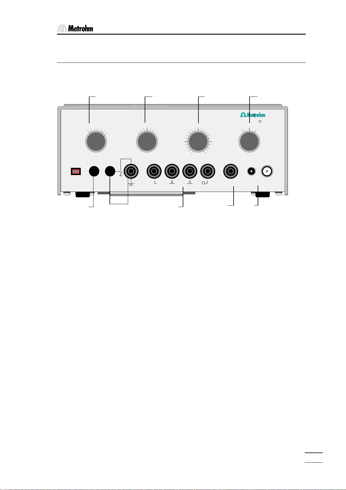
6 7 8 9
1.1 Instrument
773 pH/mV Simulator
U/mV
x10
+
x1
+
x100
-
+
-
pH
1
40
60
25
20
0
C
80
100
PT1000PT100 RE WEWEON/OFF
10
12
8
6
4
2
0
14,3k
14
16
18
20
3
pH=7
U=0mV
4 5
1000
R /M
i
~0,002
1 On/Off switch (with pilot lamp)
The instrument switches itself off automatically after 50 minutes.
2 Test of insulation resistance
3 Sockets for checking the temperature measuring input, polariza-
tion sources and conductivity meters
4 Socket for the reference electrode (RE)
5 Sockets for the working electrode (WE)
6 Selection switch for measured quantity
7 Temperature compensation for pH measurement
8 Measurement switch
9 Impedance switch: Simulation of the electrode impedance
Table on top panel with exact notation of measured values.
Battery compartment on the bottom panel (rear panel for series 2).
Type plate on rear panel.
773 pH/mV Simulator
1
Page 4
1.2. Purpose
1.2 Purpose
With the 773 pH/mV Simulator, instruments which measure potentials can be aligned and checked, e.g. Titrinos, Titroprocessors, pH
meters, ion meters, etc. In addition, the input impedance of the
measuring amplifier and the insulation resistance of the accompanying cable can be checked. The temperature measuring input, the
measuring input for polarized electrodes (Ipol) and conductivity
meters can also be checked.
The Simulator produces a pH value or a potential value in the range
from pH = ± 20.000 and U = ± 2000.00 mV respectively.
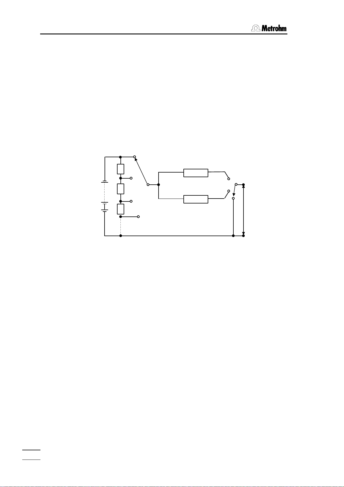
1.3 Circuit diagram
1000 MΩ
R
i
0.002 MΩ
pH=7
U=0mV
WE
U
RE
2
773 pH/mV Simulator
Page 5

2 Operation
Before you use the instrument for the first time you must insert the
batteries. The battery compartment is found on the bottom panel of
the instrument. Press the battery compartment tongue downwards
to open the compartment. Insert the 4 batteries (Mignon 1.5V-LR6)
according to the diagram in the battery compartment (take care that
the plus poles are in the correct position!).
The instrument switches itself off automatically after 50 minutes operation.
In order to avoid incorrect measurements resulting from exhausted
batteries, the 773 pH/mV Simulator switches itself off when the voltage is insufficient. The batteries must then be replaced. The batteries have a working life of approx. 1 to 2 years (depending on use).
Checking the pH
Microprocessor-controlled pH meters and titrators measure U/mV
and pH via the same analog measuring input as a potential value.
They then calculate the pH from it by using the pH calibration parameters and the temperature. The processor system is checked
each time that the instrument is switched on so that it is virtually impossible that this conversion could be incorrect and not be noticed.
This means that for microprocessor-controlled instruments only the
potential U/mV needs to be checked. Neither the pH nor the temperature compensation requires checking. This has the advantage
that the calibration parameters do not need to be set to standard
values.
1.3 Circuit diagram
773 pH/mV Simulator
3
Page 6
2.1. Aligning/Checking the potential U/mV
2.1 Aligning/Checking the potential U/mV
773 pH/mV Simulator
x10
+
x100
x1
-
+
-
+
U/mV
-
40
60
25
80
20
100
0
C
pH
10
12
8
6
14
4
PT1000PT100 RE WEWEON/OFF
16
2
18
20
0
14,3k
U=0mV
R /M
i
pH=7
1000
~0,002
6.2150.040 Cable
1. Connect the socket "WE" of the 773 pH/mV Simulator with the
measuring input of the instrument with the 6.2150.040 Cable.
For instruments with an E-plug (e.g. 670, 636) use the 6.2150.030 Cable.
For checking the instrument and its electrode cable:
Screw off the cable from the sensor and insert it in socket "WE" of the 773
pH/mV Simulator.
If you normally work with separate electrodes then remove the cable from the
reference electrode and insert it in socket "RE" of the 773.
2. Switch on the 773 pH/mV Simulator; the pilot lamp lights up.
3. Set the instrument to be checked to "Measure U".
4. Select the required factor and sign for U (switch 6).
Example with measurement switch on "2":
Switch setting Measured value
+ x1 2 mV
- x100 -200 mV
5. Set impedance switch Ri to 0.002 MΩ.
6. Set the required value with the measurement switch and read off
the measured value on the instrument being checked.
Compare this measured value with the value given in the table.
Please take into account both the resolution of your instrument’s
display and the information about tolerances given in the
‘Instructions for Use’ for your instrument.
7. Set impedance switch Ri to 1000 MΩ. The measured value on the
instrument being checked should differ from the value obtained in
step 6 by less than 1 mV.
Examples:
Set on pH Simulator Read off on instrument
1500 mV, Ri= ≈ 0.002 MΩ
1500 mV, Ri= 1000 MΩ
⇒ alignment poor, high-impedance OK.
1495 mV
1494.9 mV
Set on pH Simulator Read off on instrument
1500 mV, Ri= ≈ 0.002 MΩ
1500 mV, Ri= 1000 MΩ
1500 mV
1494.9 mV
⇒ alignment OK, high-impedance poor. Check the electrode cable!
Note: the value 0 mV can also be set directly with switch (9) (setting 0 mV).
4
773 pH/mV Simulator
Page 7

2.2 Aligning/Checking the pH
2.2 Aligning/Checking the pH
773 pH/mV Simulator
x10
+
x100
x1
-
+
-
+
U/mV
-
40
60
25
80
20
100
0
C
pH
10
12
8
6
14
4
PT1000PT100 RE WEWEON/OFF
16
2
18
20
0
14,3k
U=0mV
R /M
i
pH=7
1000
~0,002
6.2150.040 Cable
1. Connect the socket "WE" of the 773 pH/mV Simulator with the
measuring input of the instrument with the 6.2150.040 Cable.
For instruments with an E-plug (e.g. 670, 636) use the 6.2150.030 Cable.
For checking the instrument and its electrode cable:
Screw off the cable from the sensor and insert it in socket "WE" of the 773
pH/mV Simulator.
If you normally work with separate electrodes then remove the cable from the
reference electrode and insert it in socket "RE" of the 773.
2. Switch on the 773 pH/mV Simulator; the pilot lamp lights up.
3. Set slope = 1 and pHas = 7 on the instrument to be checked.
4. Set the instrument to be checked to "Measure pH".
5. Select "pH", (switch 6).
6. Set impedance switch Ri to 0.002 MΩ.
7. Select the temperature on the 773 pH/mV (switch 7). It must be
the same as the measuring temperature of the instrument being
tested.
8. Set the required value with the measurement switch and read off
the measured value on the instrument being checked.
Compare this measured value with the value given in the table.
Please take into account both the resolution of your instrument’s
display and the information about tolerances given in the
‘Instructions for Use’ for your instrument.
9. Set impedance switch Ri to 1000 MΩ. The measured value on the
instrument being checked should differ from the value obtained in
step 8 by less than pH=0.01.
Examples:
Set on pH Simulator Read off on instrument
pH=2, Ri= ≈ 0.002 MΩ
pH=2, Ri= 1000 MΩ
⇒ alignment poor, high-impedance OK.
pH=1.97
pH=1.95
773 pH/mV Simulator
Set on pH Simulator Read off on instrument
pH=2, Ri= ≈ 0.002 MΩ
pH=2, Ri= 1000 MΩ
pH=2.00
pH=1.95
⇒ alignment OK, high-impedance poor. Check the electrode cable!
Note: pH 7 can also be set directly with switch (9) (setting pH = 7).
5
Page 8

2.3. Checking the insulation of the separate reference point
2.3 Checking the insulation of the separate reference
point
773 pH/mV Simulator
x10
+
x100
x1
-
+
-
+
U/mV
-
40
60
25
80
20
100
0
C
pH
10
12
8
6
14
4
PT1000PT100 RE WEWEON/OFF
16
2
18
20
0
14,3k
U=0mV
R /M
i
pH=7
1000
~0,002
6.2150.040 Cable
6.2150.000 Cableskeep key pressed
1. Set up the instruments as for checking the U value.
2. In addition connect the earthing socket of the 773 pH/mV Simulator with the earthing socket of the instrument being checked.
For instruments with earthed measuring inputs (e.g. Titrinos) this check is irrelevant.
3. On the 773 pH/mV Simulator press the key beside the earthing
socket and keep it pressed until the measured value drift is stable.
The measured value with the key depressed should not differ by
more than 2 mV from the value obtained without pressing down
the key.
2.4 Checking the temperature compensation for pH
measurements
773 pH/mV Simulator
x10
+
x100
x1
-
+
-
+
U/mV
-
40
60
25
80
20
100
0
C
pH
10
12
8
6
14
4
PT1000PT100 RE WEWEON/OFF
16
2
18
20
0
14,3k
U=0mV
R /M
i
pH=7
1000
~0,002
6.2150.040 Cable
1. Set up the instruments as for checking the pH.
2. Set pH 13 on the 773 pH/mV Simulator.
3. Set the measuring temperature of the instrument being checked
to 0 °C. Set the temperature on the 773 pH/mV Simulator to 0 °C
as well.
The measured value must only vary within the given tolerances.
These tolerances can be found in the ‘Instructions for Use’ of the
instrument being checked.
4. Carry out the same check at 100 °C.
6
773 pH/mV Simulator
Page 9

2.5 Checking the temperature measuring input T/ C
2.5 Checking the temperature measuring input T/°C
773 pH/mV Simulator
x10
+
x100
x1
-
+
-
+
U/mV
-
40
60
25
80
20
100
0
C
pH
10
12
8
6
14
4
PT1000PT100 RE WEWEON/OFF
16
2
18
20
0
14,3k
U=0mV
R /M
i
pH=7
1000
~0,002
2 x 6.2150.000 Cables
1. Connect the sockets "PT100" and "PT1000" of the 773 pH/mV
Simulator with the temperature measuring input of the instrument
with separate 6.2150.000 Cables.
For instruments with DIN plugs (e.g. 670, 636) use 6.2150.010 Cable.
2. Set the instrument being checked to temperature measurement.
The measured value should be approx. 0 °C (exact value given in
the table - field PT100/T and PT1000/T).
3. Plug the cables into the 773 pH/mV Simulator as follows:
773 pH/mV Simulator
x10
+
x100
x1
-
+
-
+
U/mV
-
40
60
25
80
20
100
0
C
pH
10
12
8
6
14
4
16
2
18
20
0
U=0mV
R /M
i
pH=7
1000
~0,002
14,3k
PT1000PT100 RE WEWEON/OFF
2 x 6.2150.000 Cables
The measured value should be approx. 25 °C (exact value given
in the table - field Add.data, red).
This check is not possible for instruments which can only measure with Pt100
(e.g. 670, 636).
Please take into account both the resolution of your instrument’s
display and the information about tolerances given in the
‘Instructions for Use’ for your instrument.
773 pH/mV Simulator
7
Page 10

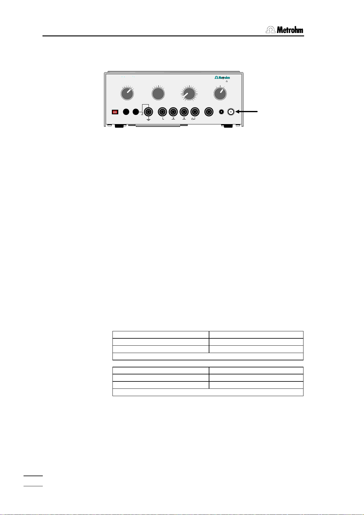
2.6. Checking the polarization source
2.6 Checking the polarization source
For microprocessor-controlled instruments it is better to check the
polarization source with the aid of the instrument diagnosis; please
refer to the ‘Instructions for Use’ of the instrument or titrator. The cable connections are shown below.
773 pH/mV Simulator
x10
+
x100
x1
-
+
-
+
U/mV
-
40
60
25
80
20
100
0
C
pH
10
12
8
6
14
4
PT1000PT100 RE WEWEON/OFF
16
2
18
20
0
14,3k
U=0mV
R /M
i
pH=7
1000
~0,002
6.2150.050 Cable
If no diagnosis instructions are available please proceed as follows:
1. Connect the sockets "14.3 kΩ" of the 773 pH/mV Simulator with
the Pol measuring input of the instrument being checked with
6.2150.050 Cable.
For instruments with banana plugs (e.g. 692) use 6.2150.000 Cables.
2. Set the instrument being checked to measurement with polarized
electrodes (Ipol).
3. The measured value depends on the polarization current and is
calculated as follows:
U = R x I = 14.3 kΩ x set polarization current
Example with Ipol = 1 uA:
Measured value U = 14.3 kΩ X 1 uA = 14.3 mV
The polarization potential source Upol can be checked similarly. The measured
value is calculated from
I = U/R
The exact values for the resistances can be found in the table on the
upper side of the instrument (field R-Test / R). Please take into account both the resolution of your instrument’s display and the information about tolerances given in the ‘Instructions for Use’ for your
instrument. With low values for the polarization current or potential
the variations may be slightly higher.
8
773 pH/mV Simulator
Page 11

2.7 Checking conductivity meters
2.7 Checking conductivity meters
773 pH/mV Simulator
x10
+
x100
x1
-
+
-
+
U/mV
-
40
60
25
80
20
100
0
C
pH
10
12
8
6
14
4
PT1000PT100 RE WEWEON/OFF
16
2
18
20
0
14,3k
U=0mV
R /M
i
pH=7
1000
~0,002
2 x 6.2150.000 Cables
1. Connect the sockets "14.3 kΩ" of the 773 pH/mV Simulator with
the measuring input of the instrument with the two 6.2150.000
Cables.
2. Note the values for the cell constant and the temperature set on
the instrument being checked. Set cell constant = 1 and the reference temperature which is valid for the instrument (20 or 25 °C).
3. Set the instrument being checked to "Measure conductivity".
4. The value should be approx. 70 uS (exact value in the table - field
R-Test / G).
5. If you are using the "Pt100" sockets of the 773 pH/mV Simulator
then the measured value should be approx. 10 mS (= 10 000 uS)
(exact value in the table - field Pt100 / G).
For the "Pt1000" sockets the measured value should be approx. 1
mS (1000 uS) (exact value in the table - field Pt1000 / G).
6. Now use the following sockets:
773 pH/mV Simulator
x10
+
x100
x1
-
+
-
+
U/mV
-
40
60
25
80
20
100
0
C
pH
10
12
8
6
14
4
16
2
18
20
0
14,3k
PT1000PT100 RE WEWEON/OFF
U=0mV
R /M
i
pH=7
1000
~0,002
2 x 6.2150.000 Cables
The measured value should be approx. 65 uS (exact value in the
table - field Add.data, green).
7. Reset the actual values for the cell constant and temperature on
the instrument being checked.
Please take into account both the resolution of your instrument’s
display and the information about tolerances given in the
‘Instructions for Use’ for your instrument.
773 pH/mV Simulator
9
Page 12

2.8. Checking the 617 and 679 Rancimats
2.8 Checking the 617 and 679 Rancimats
The measurement of the conductivity and the presentation on the
printer can be checked channel by channel. The conductivity is read
off from the display.
The temperature of the heating block is not important. It may be
necessary to create the starting condition (for 679 T> 50 °C).
773 pH/mV Simulator
x10
+
x100
x1
-
+
-
+
U/mV
-
40
60
25
80
20
100
0
C
pH
10
12
8
6
14
4
PT1000PT100 RE WEWEON/OFF
16
2
18
20
0
14,3k
U=0mV
R /M
i
pH=7
1000
~0,002
6.2150.010 Cable
1. Connect the socket "14.3 kΩ" of the 773 pH/mV Simulator with
the measuring input of the Rancimat with the 6.2150.010 Cable.
2. Note the cell constant and the printer settings. Set the cell constant to 1 and make the following printer settings:
cond.range 20 uS/cm
paper feed 20 cm/h
Press <Start> on the Rancimat.
3. The measured value should be approx. 70 uS (exact value in the
table - field R-Test / G).
Allow each channel to print out 2-3 times.
4. When the printer is not printing out an active channel make the
following connections:
10
773 pH/mV Simulator
x10
+
x100
x1
-
+
-
+
U/mV
-
40
60
25
80
20
100
0
C
pH
10
12
8
6
14
4
16
2
18
20
0
14,3k
PT1000PT100 RE WEWEON/OFF
U=0mV
R /M
i
pH=7
1000
~0,002
6.2150.010 Cable
The measured value should be approx. 65 uS (exact value in the
table - field Add.data / green).
Allow each channel to print out 2-3 times again.
5. Repeat steps 3 and 4 for all channels.
6. Measure the alteration in conductivity in the Rancimat printout.
7. Reset the actual values for the cell constant and printer settings
on the Rancimat.
773 pH/mV Simulator
Page 13

3.1 Technical data
3 Appendix
3.1 Technical data
Simulated pH values
Range........................................................................................................ pH = 0...20
Divisions ......................................................................................................... ∆pH = 1
Temperatures for pH compensation ..............................0, 20, 25, 40, 60, 80, 100 ° C
Simulated potential values
Range Divisions
U = 0...20 mV ∆U = 1 mV
U = 0...200 mV ∆U = 10 mV
U = 0...2000 mV ∆U = 100 mV
Turn-on transient
1...10 minutes after switch-on: typically 25 x 10
Influence of ambient temperature
Range Typically
U = ±0...20 mV 100 x 10
U = ±0...200 mV 20 x 10
U = ±0...2000 mV 15 x 10
Longterm stability (2 years)
Voltage source (pH/mV) .................................................................................. < 0.3 ‰
Resistance for temperature check..................................................................... < 2 ‰
Source resistances
at U = 0 mV or pH = 7...................................................................................... < 1 Ω
Ri = 1000 MΩ ± 20 %
Ri ∼ 0.002 MΩ between -20 ... +20 mV............................................max. 2.2 kΩ
-200 ... +200 mV..........................................max. 1.8 kΩ
-2000 ... +2000 mV.........................................max. 600 Ω
Power supply
4 Mignon 1.5V-LR6 batteries; 2200 mAh
Working life 1-2 years
Automatic switch-off after 50 minutes
In order to avoid incorrect measurements resulting from exhausted batteries the
pH/mV Simulator switches itself off when the voltage is insufficient.
Ambient temperature
Nominal working range ............................................................................. 0...+50 ° C
Storage and transport............................................................................. -40...+70 ° C
General construction
Safety specifications according to IEC 1010/EN61010-1, class 3
IP 40
Dimensions
Width 225 mm
Height 90 mm
Depth 95 mm
Weight .......................................................................................................................1.5 kg
-6
-6
/K
-6
/K
-6
/K
773 pH/mV Simulator
11
Page 14

3.2. Warranty and certificates
3.2 Warranty and certificates
3.2.1 Warranty
The warranty regarding our products is limited to rectification free of
charge in our workshops of defects that can be proved to be due to
material, design or manufacturing faults which appear within 12
months from the day of delivery. Transport costs are chargeable to
the purchaser.
For day and night operation, the warranty is valid for 6 months.
Glass breakage in the case of electrodes or other glass parts is not
covered by the warranty. Checks which are not a result of material or
manufacturing faults are also charged during the warranty period.
For parts of outside manufacture insofar as these constitute an appreciable part of our instrument, the warranty stipulations of the
manufacturer in question apply.
With regard to the guarantee of accuracy, the technical specifications in the Instructions for Use are authoritative.
Concerning defects in material, construction or design as well as the
absence of guaranteed features, the purchaser has no rights or
claims except those mentioned above.
If damage of the packaging is evident on receipt of a consignment
or if the goods show signs of transport damage after unpacking, the
carrier must be informed immediately and a written damage report
demanded. Lack of an official damage report releases METROHM
from any liability to pay compensation.
If any instruments and parts have to be returned, the original packaging should be used if at all possible. This applies above all to instruments, electrodes, buret cylinders and PTFE pistons. Before
embedment in wood shavings or similar material, the parts must be
packed in a dustproof package (for instruments, use of a plastic bag
is imperative). If open assemblies are enclosed in the scope of delivery that are sensitive to electromagnetic voltages (e.g. data interfaces etc.) these must be returned in the associated original protective packaging (e.g. conductive protective bag). (Exception: assemblies with built-in voltage source belong in a non-conductive protective packaging). For damage which arises as a result of noncompliance with these instructions, no warranty responsibility whatsoever will be accepted by METROHM.
3.2.2 Maintenance
12
We recommend that you have the instrument serviced by the
Metrohm Service Department at intervals of 2 years. Send it packed
in its case together with the cables supplied with it.
773 pH/mV Simulator
Page 15

3.2.3 Certificate
Certificate of Conformity and System Validation
This is to certify the conformity to the standard specifications for
electrical appliances and accessories, as well as to the standard
specifications for security and to system validation issued by the
manufacturing company.
Name of commodity: 773 pH/mV Simulator
Name of manufacturer: Metrohm Ltd., Herisau, Switzerland
This Metrohm instrument has been built and has undergone final
type testing according to the standards:
Electromagnetic compatibility: Emission
EN50081-1/92, EN55022/class B,
EN55011/class B Generic emission
3.2 Warranty and certificates
Electromagnetic compatibility: Immunity
EN50082-2/95 Immunity
IEC1000-4-2/95/class 3 Static discharge
IEC61000-4-3/95, ENV50204/93/class 3
Radiated rf electromag.field immunity
Security specifications
IEC1010 class3, EN61010 class3, UL3101-1, EN60947:IP40
The technical specifications are documented in the instruction manual.
Metrohm Ltd. is holder of the SQS certificate of the quality system
ISO 9001 for quality assurance in design/development, production,
installation and servicing.
Herisau, September 23, 1999
Dr. J. Frank Ch. Buchmann
773 pH/mV Simulator
Development Manager Production and
Quality Assurance Manager
13
Page 16

3.2. Warranty and certificates
Ionenanalytik • Analyse des ions • Ion analysis • Análisis iónico
773 pH/mV Simulator
EU Declaration of Conformity
The company Metrohm AG, Herisau, Switzerland, certifies herewith, that the following
instrument:
773 pH/mV Simulator
meets the CE mark requirements of EU Directives 89/336/EWG and 72/23/EWG.
Source of specifications:
EN 50081-1 Electromagnetic compatibility, basic specification Emitted Interference
EN 50082-2 Electromagnetic compatibility, basic specification Interference Immunity
EN 61010 Safety requirements for electrical laboratory measurement and control
equipment
Description of apparatus:
Instrument which produces exact voltage values for aligning and control of
pH/voltage measuring devices.
Herisau, September 23, 1999
14
Dr. J. Frank Ch. Buchmann
Development Manager Production and
Quality Assurance Manager
773 pH/mV Simulator
Page 17

3.3 Scope of supply and ordering information
3.3 Scope of supply and ordering information
773 pH/mV Simulator.................................................................................. 2.773.0010
including the following accessories:
1 Set of batteries, type 1.5V-LR6, 4 pcs ................................................................ 6.2133.000
2 Cables plug B/plug B.......................................................................................... 6.2150.000
1 Cable 2 x plug B/plug DIN ..................................................................................6.2150.010
1 Cable plug head G/plug E .................................................................................. 6.2150.030
1 Cable plug head G/plug F ..................................................................................6.2150.040
1 Cable plug F/2 x plug B ......................................................................................6.2150.050
1 Case..................................................................................................................... 6.2716.030
1 Instructions for Use for 773 pH/mV Simulator....................................................8.773.1003
1 Certificate for 773 Simulator
773 pH/mV Simulator
15
Page 18

Index
Index
Accessories................................................ 15
Alignment ................................................... 4ff
Appendix .................................................... 11
Batteries .......................................................3
Cable..........................................................15
CE sign....................................................... 14
Certificates .................................................13
Circuit diagram............................................. 2
Conductivity .................................................9
Connection cables..................................... 15
Impedance switch........................................1
Insulation resistance ....................................6
Introduction ..................................................2
ISO .............................................................13
Maintenance...............................................12
Operation .....................................................3
Ordering information .................................. 15
Overview....................................................... 1
pH alignment................................................ 5
Polarization current ......................................8
Polarization voltage......................................8
Potential alignment.......................................4
Purpose........................................................2
Rancimat .................................................... 10
Scope of supply......................................... 15
Switches.......................................................1
Technical data............................................ 11
Temperature alignment................................7
Temperature compensation......................... 6
Titrators ........................................................4
U/mV ............................................................4
Voltage alignment ........................................4
Warranty ..................................................... 12
16
773 pH/mV Simulator
 Loading...