


Makita EBH341U Manual
Original Instruction Manual Instructions d’emploi d’origine Originalbetriebsanleitung Manuale di istruzioni originale Originele gebruiksaanwijzing Instrucciones de manejo originales Instruções de serviço original Original brugsanvisning Πρωτότυπο εγχειρίδιο οδηγιών Orijinal Kullanım Kılavuzu
Important:
Read this instruction manual carefully before putting the Petrol Brushcutter into operation and strictly observe the safety regulations! Preserve instruction manual carefully!
Important :
Veuillez lire attentivement ce mode d’emploi avant d’utiliser la débroussailleuse thermique et respectez strictement les consignes de sécurité !
Veillez à conservez ce manuel d’instructions !
Wichtig:
Lesen Sie vor Verwendung der Motorsense diese Betriebsanleitung aufmerksam durch und halten Sie die Sicherheitsbestimmungen strikt ein! Bewahren Sie diese Betriebsanleitung sorgfältig auf!
Importante:
Leggere attentamente il presente manuale di istruzioni prima di mettere in funzione il decespugliatore a benzina e rispettare scrupolosamente le norme per la sicurezza.
Conservare con cura il manuale di istruzioni.
Belangrijk:
Lees deze gebruiksaanwijzing aandachtig door voordat u de benzinebosmaaier in gebruik neemt en houdt u te allen tijde aan de veiligheidsinstructies!
Bewaar deze gebruiksaanwijzing zorgvuldig!
Importante:
Lea atentamente este manual de instrucciones antes de utilizar la desbrozadora y cumpla estrictamente la normativa de seguridad. Conserve el manual de instrucciones con cuidado.
Importante:
Leia cuidadosamente este manual de instruções antes de utilizar a Roçadeira a Gasolina e cumpra todas as normas de segurança! Guarde este manual de instruções num local seguro!
Vigtigt:
Læs denne brugsanvisning omhyggeligt igennem inden du anvender den benzindrevne buskrydder og overhold sikkerhedsbestemmelserne til mindste detalje!
Gem denne brugsanvisning omhyggeligt!
Σημαντικό:
Πριν θέσετε σε λειτουργία τον Βενζινοκίνητο Θαμνοκοπτικό διαβάσετε προσεχτικά το παρόν εγχειρίδιο οδηγιών και εφαρμόσετε αυστηρά τους κανονισμούς ασφαλείας.
Διατηρήστε με προσοχή το εγχειρίδιο οδηγιών!
Önemli:
Benzinli Yan Tırpanı kullanmaya başlamadan önce bu kullanım kılavuzunu dikkatli bir şekilde okuyun ve güvenlik talimatlarını harfiyen takip edin!
Kullanım kılavuzunu dikkatlice saklayın!
EBH341U |
EBH341L |
English |
(Original instructions) |
Thank you very much for purchasing the MAKITA Petrol Brushcutter. We are pleased to recommend to you the MAKITA Petrol Brushcutter which is the result of a long development programme and many years of knowledge and experience.
Please read this booklet which refers in detail to the various points that will demonstrate its outstanding performance. This will assist you to obtain the best possible result from your MAKITA Petrol Brushcutter.
Table of Contents |
Page |
Symbols......................................................................... |
2 |
Safety instructions ......................................................... |
3 |
Technical data................................................................ |
7 |
Designation of parts....................................................... |
8 |
Mounting of handle........................................................ |
9 |
Mounting of protector................................................... |
10 |
Mounting of cutter blade or nylon cutting head............ |
11 |
Before start of operation.............................................. |
12 |
Correct handling of machine........................................ |
14 |
Points in operation and how to stop ............................ |
14 |
Resharpening the cutting tool...................................... |
16 |
Servicing instructions................................................... |
18 |
Storage........................................................................ |
22 |
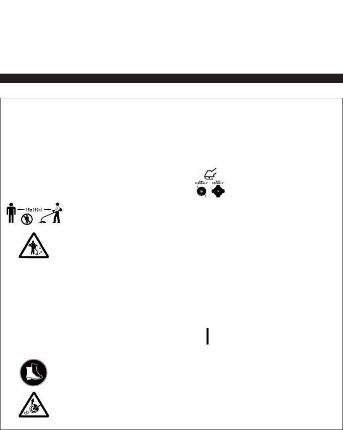
SYMBOLS
You will note the following symbols when reading the instructions manual.
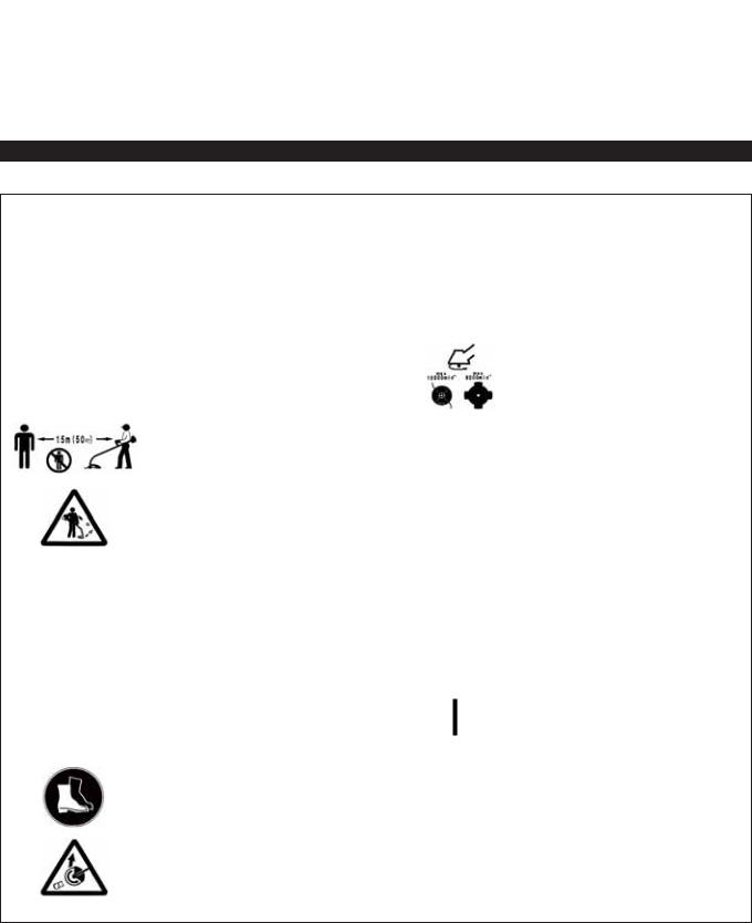
Read instruction manual and follow the warnings and safety precautions!
Take Particular care and attention!
Forbidden!
Keep distance!
Flying object hazard!
No smoking!
No open flame!
Protective gloves must be worn!
Wear sturdy boots with nonslip soles. Steeltoed safety boots are recommended!
Keep the area of operation clear of all persons and pets!
Wear protective helmet, eye and ear protection!
Top permissible tool speed
Fuel (Gasoline)
Engine-manual start
Emergency stop
First Aid
ON/START
OFF/STOP
Kickback!
2

SAFETY INSTRUCTIONS
General Instructions
–Read this instruction manual to become familiar with handling of the equipment. Users insufficiently informed will risk danger to themselves as well as others due to improper handling.
–It is recommended only to lend the equipment to people who have proven to be experienced.
Always hand over the instruction manual.
–First users should ask the dealer for basic instructions to familiarize oneself with the handling of brushcutters.
–Children and young persons aged under 18 years must not be allowed to operate this equipment. Persons over the age of 16 years may however use the device for the purpose of being trained while under supervision of a qualified trainer.
–Use with the utmost care and attention.
–Operate only if you are in good physical condition. Perform all work calmly and carefully. The user has to accept liability for others.
–Never use this equipment after consumption of alcohol or drugs, or if feeling tired or ill.
–National regulation can restrict the use of the machine.
Intended use of the machine
–This equipment is only intended for cutting grass, weeds, bushes, undergrowth. It should not be used for any other purpose such as edging or hedge cutting as this may cause injury.
Personal protective equipment
–The clothing worn should be functional and appropriate, i.e. it should be tightfitting but not cause hindrance. Do not wear either jewelry or clothing which could become entangled with bushes or shrubs.
–In order to avoid either head-, eye-, hand-or foot injuries as well as to protect your hearing the following protective equipment and protective clothing must be used during operation.
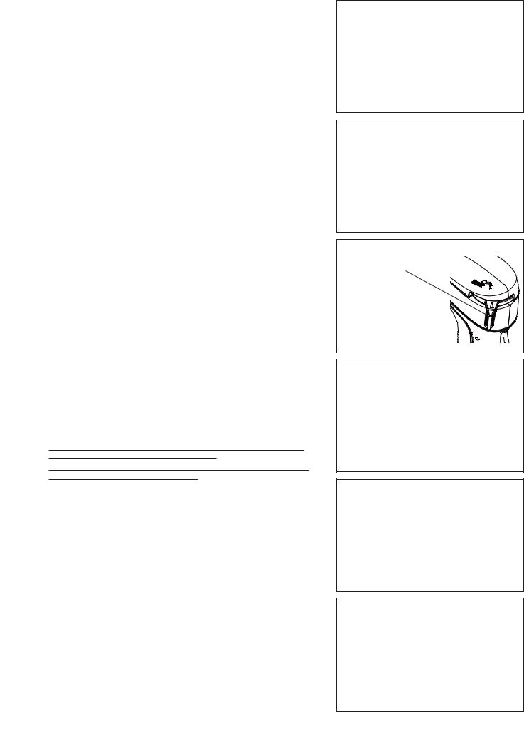
–Always wear a helmet where there is a risk of falling objects. The protective helmet (1) is to be checked at regular intervals for damage and is to be replaced at the latest after 5 years. Use only approved protective helmets.
–The visor (2) of the helmet (or alternatively goggles) protects the face from flying debris and stones. During operation always wear goggles, or a visor to prevent eye injuries.
–Wear adequate noise protection equipment to avoid hearing impairment (ear muffs (3), ear plugs etc.).
–The work overalls (4) protect against flying stones and debris. We strongly recommend that the user wears work overalls.
–Gloves (5) are part of the prescribed equipment and must always be worn during operation.
–When using the equipment, always wear sturdy shoes (6) with a non-slip sole. This protects against injuries and ensures a good footing.
Starting up the brushcutter
–Please make sure that there are no children or other people within a working range of 15 meters (50 ft), also pay attention to any animals in the working vicinity.
–Before use always check the equipment is safe for operation:
Check the security of the cutting tool, the throttle lever for easy action and check for proper functioning of the throttle lever lock.
–Rotation of the cutting tool during idling speed is not allowed. Check with your dealer for adjustment if in doubt. Check for clean and dry handles and test the function of the start/stop switch.
Diagrammatic figure
15 Meters
3
Start the brushcutter only in accordance with the instructions.
–Do not use any other methods for starting the engine!
–Use the brushcutter and the tools only for such applications as specified.
–Only start the engine, after the entire assembly is done. Operation of the device is only permitted after all the appropriate accessories are attached!
–Before starting make sure that the cutting tool has no contact with hard objects such as branches, stones etc. as the cutting tool will revolve when starting.
–The engine is to be switched off immediately in case of any engine problems.
–Should the cutting tool hit stones or other hard objects, immediately switch off the engine and inspect the cutting tool.
–Inspect the cutting tool at short regular intervals for damage (detection of hairline cracks by means of tapping-noise test).
–If the equipment gets heavy impact or fall, check the condition before continuing work. Check the fuel system for fuel leakage and the controls and safety devices for malfunction. If there is any damage or doubt, ask our authorized service center for the inspection and repair.
–Operate the equipment only with the shoulder harness attached which is to be suitably adjusted before putting the brushcutter into operation. It is
essential to adjust the shoulder harness according to the user size to prevent fatigue occurring during use. Never hold the cutter with one hand during use.
–During operation always hold the brushcutter with both hands. Always ensure a safe footing.
–Operate the equipment in such a manner as to avoid inhalation of the exhaust gases. Never run the engine in enclosed rooms (risk of gas poisoning). Carbon monoxide is an odorless gas.
–Switch off the engine when resting and when leaving the equipment unattended, and place it in a safe location to prevent danger to others or damage to the machine.
–Never put the hot brushcutter onto dry grass or onto any combustible materials.
–Always install the approved cutting tool guard onto the equipment before starting the engine.
Otherwise contact with the cutting tool may cause serious injury.
–All protective installations and guards supplied with the machine must be used during operation.
–Never operate the engine with faulty exhaust muffler.
–Shut off the engine during transport.
–When transporting the equipment, always attach the cover to the cutting blade.
–Ensure safe position of the equipment during car transportation to avoid fuel leakage.
–When transporting, ensure that the fuel tank is completely empty.
–When unloading the equipment from the truck, never drop the Engine to the ground or this may severely damage the fuel tank.
–Except in case of emergency, never drop or cast the equipment to the ground or this may severely damage the equipment.
–Remember to lift the entire equipment from the ground when moving the equipment. Dragging the fuel tank is highly dangerous and will cause damage and leakage of fuel, possibly causing fire.
Refueling
–Shut off the engine during refueling, keep away from open flames and do not smoke.
–Avoid skin contact with mineral oil products. Do not inhale fuel vapor. Always wear protective gloves during refueling. Change and clean protective clothing at regular intervals.
–Take care not to spill either fuel or oil in order to prevent soil contamination (environmental protection). Clean the brushcutter immediately after fuel has been spilt.
–Avoid any fuel contact with your clothing. Change your clothing instantly if fuel has been spilt on it (to prevent clothing catching fire).
–Inspect the fuel cap at regular intervals making sure that it can be securely fastened and does not leak.
–Carefully tighten the fuel tank cap. Change location to start the engine (at least 3 meters away from the place of refueling).
–Never refuel in closed rooms. Fuel vapors accumulate at ground lever (risk of explosions).
–Only transport and store fuel in approved containers. Make sure the fuel stored is not accessible to children.
• Resting
•Transport
•Refuelling
•Maintenance
•Tool replacement
3
4

Method of operation
–Only use in good light and visibility. During the winter season beware of slippery or wet areas, ice and snow (risk of slipping). Always ensure a safe footing.
–Never cut above waist height.
–Never stand on a ladder.
–Never climb up into trees to perform cutting operation.
–Never work on unstable surfaces.
–Remove sand, stones, nails etc. found within the working range. Foreign particles may damage the cutting tool and can cause dangerous kick-backs.
–Before commencing cutting, the cutting tool must have reached full working speed.
–When using metal blades, swing the tool evenly in half-circle from right to left, like using a scythe.
If grass or branches get caught between the cutting tool and guard, always stop the engine before cleaning. Otherwise unintentional blade rotation may cause serious injury.
–Take a rest to prevent loss of control caused by fatigue. We recommend to take a 10 to 20-minute rest every hour.
Cutting Tools
–Use an applicable cutting tool for the job in hand.
Nylon cutting heads (string trimmer heads) are suitable for trimming lawn grass.
Metal blades are suitable for cutting weeds, high grasses, bushes, shrubs, underwood, thicket, and the like.
Never use other blades including metal multi-piece pivoting chains and flail blades. Otherwise serious injury may result.
–When using metal blades, avoid “kickback” and always prepare for an accidental kickback. See the section “Kickback” and “Kickback prevention.”
Kickback (blade thrust)
–Kickback (blade thrust) is a sudden reaction to a caught or bound cutting blade. Once it occurs, the equipment is thrown sideway or toward the operator at great force and it may cause serious injury.
–Kickback occurs particularly when applying the blade segment between 12 and 2 o’clock to solids, bushes and trees with 3 cm or larger diameter.
–To avoid kickback:
•Apply the segment between 8 and 11 o’clock;
•Never apply the segment between 12 and 2 o’clock;
•Never apply the segment between 11 and 12 o’clock and between 2 and
5 o’clock, unless the operator is well trained and experienced and does it at his/her own risk;
•Never use cutting blades close to solids, such as fences, walls, tree trunks and stones;
•Never use cutting blades vertically, for such operations as edging and trimming hedges.
Vibration
–People with poor circulation who are exposed to excessive vibration may experience injury to blood vessels or the nervous system. Vibration may cause the following symptoms to occur in the fingers, hands or wrists: “Falling asleep” (numbness), tingling, pain, stabbing sensation, alteration of skin color or of the skin. If any of these symptoms occur, see a physician!
–To reduce the risk of “white finger disease”, keep your hands warm during operation and well maintain the equipment and accessories.
Maintenance instructions
–Have your equipment serviced by our authorized service center, always using only genuine replacement parts. Incorrect repair and poor maintenance can shorten the life of the equipment and increase the risk of accidents.
–The condition of the cutter, in particular of the cutting tool of the protective devices and also of the shoulder harness must be checked before commencing work. Particular attention is to be paid to the cutting blades which must be correctly sharpened.
–Turn off the engine and remove spark plug connector when replacing or sharpening cutting tools, and also when cleaning the cutter or cutting tool.
Caution:
Kickback
Diagrammatic figure
Diagrammatic figure
5

Never straighten or weld damaged cutting tools.
–Pay attention to the environment. Avoid unnecessary throttle operation for less pollution and noise emissions. Adjust the carburetor correctly.
–Clean the equipment at regular intervals and check that all screws and nuts are well tightened.
–Never service or store the equipment in the vicinity of naked flames.
–Always store the equipment in locked rooms and with an emptied fuel tank.
–When cleaning, servicing and storing the equipment, always attach the cover to the cutting blade.
Observe the relevant accident prevention instructions issued by the relevant trade associations and by the insurance companies. Do not perform any modifications to the equipment as this will endanger your safety.
The performance of maintenance or repair work by the user is limited to those activities as described in the instruction manual. All other work is to be done by an Authorized Service Agent. Use only genuine spare parts and accessories released and supplied by MAKITA.
Use of non-approved accessories and tools means increased risk of accidents.
MAKITA will not accept any liability for accidents or damage caused by the use of non-approved cutting tools and fixing devices of cutting tools, or accessories.
First Aid
In case of accident make sure that a first-aid box is available in the vicinity of the cutting operations. Immediately replace any item taken from the first aid box.
When asking for help, please give the following information:
–Place of accident
–What happened
–Number of injured persons
–Kind of injuries
–Your name
For European countries only
EC Declaration of Conformity
We Makita Corporation as the responsible manufacturer declare that the following Makita machine(s):
Designation of Machine: Petrol Brushcutter Model No./ Type: EBH341U, EBH341L Specifications: see “TECHNICAL DATA” table
are of series production and
Conforms to the following European Directives:
2000/14/EC, 2006/42/EC
And are manufactured in accordance with the following standards or standardized documents: EN ISO 11806-1
The technical documentation is kept by:
Makita International Europe Ltd., Technical Department,
Michigan Drive, Tongwell, Milton Keynes, Bucks MK15 8JD, England
The conformity assessment procedure required by Directive 2000/14/EC was in Accordance with annex V. Measured Sound Power Level: 109.7 dB
Guaranteed Sound Power Level: 111 dB
31. 8. 2009
Tomoyasu Kato
Director
Makita Corporation
3-11-8, Sumiyoshi-cho,
Anjo, Aichi, JAPAN
6

TECHNICAL DATA EBH341U, EBH341L
|
|
Model |
|
EBH341U |
|
EBH341L |
|
|
|
|
|
|
|
||
|
|
|
Bike handle |
|
Loop handle |
||
|
|
|
|
|
|
||
|
|
|
|
|
|
|
|
Dimensions: length x width x height (without cutting blade) |
mm |
1,810 x 620 x 500 |
|
1,810 x 330 x 275 |
|||
|
|
|
|
|
|
|
|
Mass (without plastic guard and cutting blade) |
kg |
7.1 |
|
6.7 |
|||
|
|
|
|
|
|
|
|
Volume (fuel tank) |
|
|
L |
|
0.65 |
||
|
|
|
|
|
|
|
|
Volume (oil tank) |
|
|
L |
|
0.1 |
||
|
|
|
|
|
|
|
|
Engine displacement |
|
|
cm3 |
|
33.5 |
||
|
|
|
|
|
|
|
|
Maximum engine performance |
|
ISO8893 |
kw |
1.07 at 7,000 min-1 |
|||
|
|
|
|
|
|
|
|
Maximum rotational frequency of the spindle |
min-1 |
|
6,850 |
||||
|
|
|
|
|
|
|
|
Engine speed at recommended max. spindle rotational frequency |
min-1 |
|
10,000 |
||||
|
|
|
|
|
|
|
|
Fuel consumption at max. engine performance ISO8893 |
kg/h |
|
0.458 |
||||
|
|
|
|
|
|
|
|
Specific fuel consumption at max. engine performance |
g/kwh |
|
426 |
||||
|
|
|
|
|
|
|
|
Engine speed at idling |
|
|
min-1 |
|
3,000 |
||
|
|
|
|
|
|
|
|
Clutch engagement speed |
|
|
min-1 |
|
4,100 |
||
|
|
|
|
|
|
|
|
Carburetor (Diaphragm - carburetor) |
type |
|
WALBRO WYL |
||||
|
|
|
|
|
|
|
|
Ignition system |
|
|
type |
Solid state ignition |
|||
|
|
|
|
|
|
|
|
Spark plug |
|
|
type |
|
NGK CMR4A |
||
|
|
|
|
|
|
|
|
Electrode gap |
|
|
mm |
|
0.7 - 0.8 |
||
|
|
|
|
|
|
|
|
|
Right handle |
|
ahv eq |
m/s2 |
3.3 |
|
6.1 |
|
(Rear grip) |
|
Uncertainty K |
2 |
0.70 |
|
2.0 |
Vibration per |
|
|
m/s |
|
|||
|
|
|
|
|
|
|
|
ISO 22867 |
Left handle |
|
ahv eq |
2 |
2.5 |
|
7.4 |
|
|
m/s |
|
||||
|
(Front grip) |
|
Uncertainty K |
2 |
1.26 |
|
0.63 |
|
|
|
m/s |
|
|||
Sound pressure level average to |
|
LPA eq |
dBA |
|
98.2 |
||
ISO 22868 |
|
Uncertainty K |
dBA |
|
2.1 |
||
|
|
|
|
||||
|
|
|
|
|
|
||
Sound power level average to |
|
LWA eq |
dBA |
|
106.7 |
||
ISO 22868 |
|
Uncertainty K |
dBA |
|
1.3 |
||
|
|
|
|
||||
|
|
|
|
|
|||
Fuel |
|
|
|
Automobile gasoline |
|||
|
|
|
|
|
|
||
Engine Oil |
|
|
|
SAE 10W-30 oil of API Ciassification, |
|||
|
|
|
Class SF or higher (4-stroke engine for automobile) |
||||
|
|
|
|
|
|||
|
|
|
|
|
|||
Cutting tools (cutter blade dia.) |
|
|
mm |
305 (with three blades) |
|||
|
|
|
|
|
|
||
Gear ratio |
|
|
|
|
13/19 |
||
|
|
|
|
|
|
|
|
7
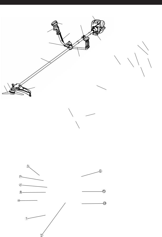
DESIGNATION OF PARTS
EBH341U
EBH341L
GB |
DESIGNATION OF PARTS |
1 |
Fuel Tank |
2 |
Rewind Starter |
|
|
3 |
Air Cleaner |
|
|
4 |
I-O Switch (on/off) |
|
|
5 |
Spark Plug |
6 |
Exhaust Muffler |
7 |
Clutch Case |
|
|
9 |
Hanger |
|
|
10 |
Handle |
|
|
11 |
Throttle Lever |
12 |
Control Cable |
|
|
13 |
Shaft |
|
|
14 |
Protector (Cutting tool guard) |
|
|
15 |
Gear Case/Head Case |
16 |
Handle Holder |
17 |
Cutter Blade |
|
|
18 |
Nylon Cutting Head |
|
|
19 |
Fuel Filler Cap |
|
|
20 |
Starter Knob |
21 |
Primer Pump |
22 |
Choke Lever |
|
|
23 |
Exhaust Pipe |
|
|
24 |
Oil Gauge |
8
MOUNTING OF HANDLE
CAUTION: Before doing any work on the Petrol Brushcutter, always stop the engine and pull the spark plug connector off the spark plug. Always wear protective gloves!
CAUTION: Start the Petrol Brushcutter only after having assembled it completely.
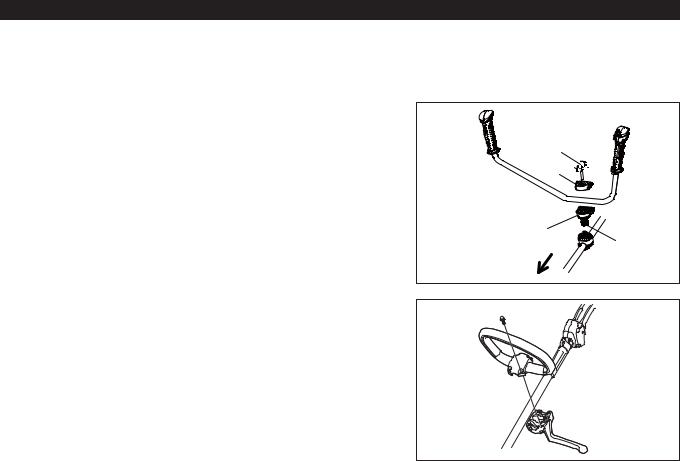
For machines with bike handle models
–Loosen knob (1).
–Place handle (4) between handle clamp (2) and handle holder (3).
–Adjust handle (4) to an angle that provides a comfortable working position and then secure by firmly hand-tightening knob (1).
CAUTION: Do not forget to mount spring (5).
For machines with loop handle
–Fix a barrier to the left side of the machine together with the handle for operator protection.
–Make sure that the grip/barrier assembly is fitted between the spacer and the arrow mark.
WARNING: Do not remove or shrink the spacer. The spacer keeps a certain distance between both hands. Setting the grip/barrier assembly close to the other grip beyond the length of the spacer may cause loss of control and serious personal injury.


Engine
 Engine
Arrow mark 
9
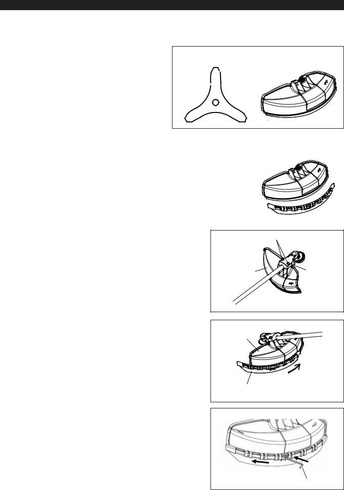
MOUNTING OF PROTECTOR
To meet the applicable safety provisions, only the tool/protector combinations as indicated in the table must be used.
Be sure to use genuine MAKITA cutter blades or nylon cutting head.
–The cutter blade must be well polished, free of cracks or breakage. If the cutter blade hits against a stone during operation, stop the engine and check the blade immediately.
–Resharpening or replace the cutter blade every three hours of operation.
–If the nylon cutting head hits against a stone during operation, stop the engine and check the nylon cutting head immediately.
CAUTION: The appropriate protector must always be installed, for your own safety and in order to comply with accidentprevention regulations.
Operation of the equipment without the guard being in place is not permitted.
The outside diameter of the cutter blade must be 255 mm (10”). Cutter blades with outside diameter of 305 mm or 12 inches can be used only for those with three blades.
Metal blade |
Protector for metal blades |
|
|
Nylon cutting head |
|
|
|
|
Protector for |
|||||||||||||||||||||||||||||||||||
|
|
|
|
nylon cutting head |
||||||||||||||||||||||||||||||||||||||
|
|
|
|
|
|
|
|
|
|
|
|
|
|
|
|
|
|
|
|
|
|
|
|
|
|
|
|
|
|
|
|
|
|
|
|
|
|
|
|
|
|
|
|
|
|
|
|
|
|
|
|
|
|
|
|
|
|
|
|
|
|
|
|
|
|
|
|
|
|
|
|
|
|
|
|
|
|
|
|
|
|
|
|
|
|
|
|
|
|
|
|
|
|
|
|
|
|
|
|
|
|
|
|
|
|
|
|
|
|
|
|
|
|
|
|
|
|
|
|
|
|
|
|
|
|
|
|
|
|
|
|
|
|
|
|
|
|
|
|
|
|
|
|
|
|
|
|
|
|
|
|
|
|
|
|
|
|
|
|
|
|
|
|
|
|
|
|
|
|
|
|
|
|
|
|
|
|
|
|
|
|
|
|
|
|
|
|
|
|
|
|
|
|
|
|
|
|
|
|
|
|
|
|
|
|
|
|
|
|
|
|
|
|
|
|
|
|
|
|
|
|
|
|
|
|
|
|
|
|
|
|
|
|
|
|
|
|
|
|
|
|
|
|
|
|
|
|
|
|
|
|
|
|
|
|
|
|
|
|
|
|
|
|
|
|
|
|
|
|
|
|
|
|
|
|
|
|
|
|
|
|
|
|
|
|
|
|
|
|
|
|
|
|
|
|
|
|
|
|
|
–In use of the metal blade, fix the protector (3) to the clamp (2) with two bolts M6 x 30 (1).
NOTE: Tighten the right and left bolts evenly so that the gap between the clamp
(2) and the protector (3) will be constant.
Otherwise, the protector sometimes may not function as specified.
–In cases where the nylon cord cutter is to be used, be sure to mount the nylon cord cutter protector (4) onto the metal blade protector (3).
–Mount the nylon cord cutter protector (4) by sliding it into place from the flank of the metal blade protector (3) as shown.
–Remove tape adhered to cutter, which cuts nylon cord, on nylon cord cutter protector (4).
CAUTION: Be sure to push in nylon cord cutter protector (4) until it is fully inserted.
Take care not to injure yourself on the cutter for cutting the nylon cord.
–To remove the nylon cord cutter protector (4), apply a hex wrench into the notch on the metal blade protector (3), push it in and meanwhile slide the nylon cord cutter protector (4).
|
(1) |
(3) |
(2) |
|
(3)
(4)
Hex wrench
10
MOUNTING OF CUTTER BLADE OR NYLON CUTTING HEAD
Turn the machine upside down, and you can replace the cutter blade or nylon cutting head easily.
–Insert the hex wrench through the hole in the gear case and rotate the receiver washer (4) until it is locked with the hex wrench.
–Loosen the nut (1) (left-hand thread) with the socket wrench and remove the nut (1), cup (2), and clamp washer (3).
(4) |
Hex wrench |
(3) |
(2) |
(1) |
Mounting of cutterblade
With the hex wrench still in place.
–Mount the cutter blade onto the shaft so that the guide of the receiver washer
(4) fits in the arbor hole in the cutter blade. Install the clamp washer (3), cup (2), and secure the cutter blade with the nut (1).
[Tightening torque: 13 - 23 N-m]
NOTE: Always wear gloves when handling the cutter blade.
NOTE: The cutter blade-fastening nut (with spring washer) is a consumable part.
If there appears any wear or deformation on the spring washer, replace the nut.
Mounting of nylon cutting head
–The clamp washer (3), cup (2), and nut (1) are not necessary for mounting the nylon cutting head. The nylon cutting head should go on top of the receiver washer (4).
–Insert the hex wrench through the hole in the gear case and rotate the receiver washer (4) until it is locked with the hex wrench.
–Then screw the nylon cutting head onto the shaft by turning it counterclockwise.
–Remove the hex wrench.
–Make sure that the blade is the left way up.
Hex wrench
Loosen Tighten
(4)
Hex wrench
Rotation
11

BEFORE START OF OPERATION
Inspection and refill of engine oil
–Perform the following procedure, with the engine cooled down.
–While keeping the engine level, remove the oil gauge, and confirm that the oil is filled within the upper and lower limit marks.
When the oil is in short in such a way that the oil gauge touches the oil only by its tip, in particular with the oil gauge remaining inserted in the crankcase without screwing-in (Fig. 1), refill new oil near the port (Fig. 2).
–For reference, the oil refill time is about 15 h (refill frequency: 15 times).
If the oil changes in color or mixes with dirt, replace it with new one. (For the interval and method of replacement, refer to P18 - 19)
Recommended oil: SAE 10W-30 oil of API Classification, Class SF or higher (4-stroke engine for automobile) Oil volume: Approx. 0.1 L
Note: If the engine is not kept upright, oil may go into around the engine, and may be refilled excessively.
If the oil is filled above the limit, the oil may be contaminated or may catch fire with white smoke.
Point 1 in Replacement of oil: “Oil gauge”
–Remove dust or dirt near the oil refill port, and detach the oil gauge.
–Keep the detached oil gauge free of sand or dust. Otherwise, any sand or dust adhering to the oil gauge may cause irregular oil circulation or wear on the engine parts, which will result in troubles.
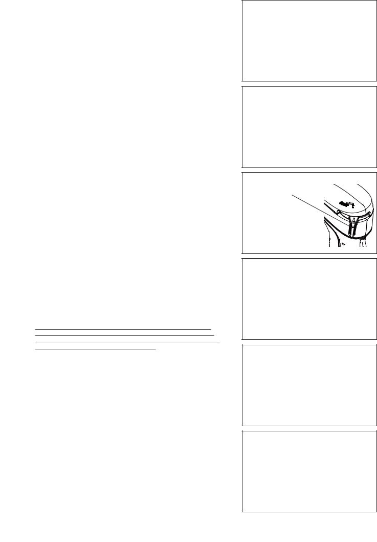
–As an example to keep the oil gauge clean, it is recommended to insert the oil gauge on its knob side into the engine cover, as shown in Fig. 3.
If oil adheres around this tip, refill new oil.
Upper limit of oil level (Lower part of oil refill port threaded part)
Oil gauge
Fig. 3
Fig. 1 |
Fig. 2 |
(1) Keep the engine level, and detach the oil gauge.
(2)Fill oil up to the edge of the oil refill port. (Refer to Fig. 2). Feed oil with the lubricant refill container.
(3)Securely tighten the oil gauge. Insufficient tightening may cause oil leakage.
Point 2 in Replacement of oil: “If oil spills out”
–If oil spills out between the fuel tank and engine main unit, the oil is sucked into through the cooling air intake port, which will contaminate the engine. Be sure to wipe out spilt oil before start of operation.
12

REFUELING
Handling of fuel
It is necessary to handle fuel with utmost care. Fuel may contain substances similar to solvents. Refueling must be performed in a sufficiently ventilated room or in the open air. Never inhale fuel vapor, and keep fuel away from you. If you touch fuel repeatedly or for a long time, the skin becomes dry, which may cause skin disease or allergy. If fuel enters into the eye, clean the eye with fresh water. If your eye remains still irritated, consult your doctor.
Storage period of fuel
Fuel should be used up within a period of 4 weeks, even if it is kept in a special container in a well-ventilated shade. If a special container is not used or if the container is not covered, fuel may deteriorate in one day.
STORAGE OF MACHINE AND REFILL TANK
–Keep the machine and tank at a cool place free from direct sunshine.
–Never keep the fuel in the cabin or trunk.
Fuel
The engine is a four-stroke engine. Be sure to use an automobile gasoline (regular gasoline or premium gasoline).
Points for fuel
–Never use a gasoline mixture which contains engine oil. Otherwise, it will cause excessive carbon accumulation or mechanical troubles.
–Use of deteriorated oil will cause irregular startup.
Refueling
WARNING: INFLAMMABLES STRICTLY PROHIBITED
Gasoline used: Automobile gasoline (unleaded gasoline)
–Loosen the tank cap a little so that there will be no difference in atmospheric pressure.
–Detach the tank cap, and refuel, discharging air by tilting the fuel tank so that the refuel port will be oriented upward. (Never refill fuel full to the oil refill port.)
–Wipe well the periphery of the tank cap to prevent foreign matter from entering into the fuel tank.
–After refueling, securely tighten the tank cap.
●If there is any flaw or damage on the tank cap, replace it.
●The tank cap is consumable, and therefore should be renewed every two to three years.
Fuel tank cap
Fuel upper limit
Fuel tank
13
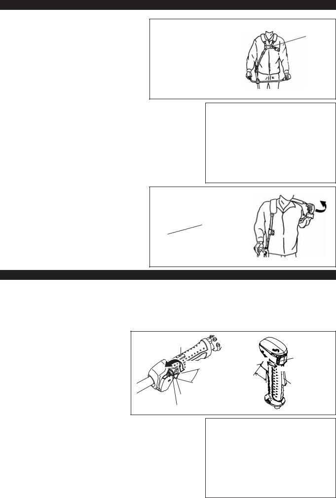
CORRECT HANDLING OF MACHINE
Attachment of shoulder strap |
|
– Adjust the strap length so that the cutter blade will be |
Buckle |
kept parallel with the ground. |
|
For EBH341U |
|
NOTE: Be careful not to trap clothing, etc., in the buckle. |
|
EBH341U
Detachment |
|
For EBH341L |
|
– In an emergency, push the notches (1) at both sides, and you can detach the |
|
machine from you. |
|
Be extremely careful to maintain control of the machine at this time. Do not |
|
allow the machine to be deflected toward you or anyone in the work vicinity. |
|
WARNING: Failure to maintain complete control of the machine at all could |
(1) |
result in serious bodily injury or DEATH. |
|
|
Hanger |
For EBH341U
–In an emergency, push the notches (2) at both sides, and you can detach the machine from you.
Be extremely careful to maintain control of the machine at this time. Do not allow the machine to be deflected toward you or anyone in the work vicinity.
WARNING: Failure to maintain complete control of the
machine at all could result in serious bodily (2) injury or DEATH.
POINTS IN OPERATION AND HOW TO STOP
Observe the applicable accident prevention regulations!
STARTING
Move at least 3 m away from the place of refuelling. Place the Petrol Brushcutter on a clean piece of ground taking care that the cutting tool does not come into contact with the ground or any other objects.
A: Cold start |
Lock-off lever |
|
|
|
1) Set this machine on a flat space. |
|
|
||
OPERATION |
|
|
|
|
|
|
STOP |
(1) |
|
|
|
STOP |
||
|
|
Throttle lever |
OPERATION |
|
|
|
High speed |
||
|
|
|
Low speed |
|
|
|
Low speed |
High speed |
|
|
|
Throttle lever |
|
|
|
|
|
|
|
|
(1) |
EBH341L |
|
EBH341U |
2) Set the I-O switch (1) to OPERATION. |
|
|
|
|
3) Choke lever |
|
|
|
CLOSE |
Close the choke lever. |
|
|
|
|
Choke opening: |
|
|
|
|
–Full closing in cold or when the engine is cold.
–Full or half opening in restart just after stop of operation.
14
4)Primer pump
Continue to push the primer pump until fuel enters into the primer pump. (In general, fuel enters into the primer pump by 7 to 10 pushes.)
If the primer pump is pushed excessively, an excess of gasoline returns to the fuel tank.
5)Recoil starter
Pull the start knob gently until it is hard to pull (compression point). Then, return the start knob, and pull it strongly.
Never pull the rope to the full. Once the start knob is pulled, never release your hand immediately. Hold the start knob until it returns to its original point.
6)Choke lever
When the engine starts, open the choke lever.
–Open the choke lever progressively while checking the engine operation. Be sure to open the choke lever to the full in the end.
–In cold or when the engine is cooled down, never open the choke lever suddenly. Otherwise, the engine may stop.
7)Warm-up operation
Continue warm-up operation for 2 to 3 minutes.
Carburetor
Primer Pump
OPEN
Note: –If the starter handle is pulled repeatedly when the choke lever remains at “CLOSE” position, the engine will not start easily due to excessive fuel intake.
–In case of excessive fuel intake, remove the spark plug and pull the starter handle slowly to remove excess fuel. Also, dry the electrode section of the spark plug.
Caution during operation:
If the throttle lever is opened fully in a no-load operation, the engine rotation is increased to 10,000 min-1 or more. Never operate the engine at a higher speed than required and at an approximate speed of 6,000 - 8,500 min-1.
B: Startup after warm-up operation
1)Push the primer pump repeatedly.
2)Keep the throttle lever at the idling position.
3)Pull the recoil starter strongly.
4)If it is difficult to start the engine, open the throttle by about 1/3. Pay attention to the cutter blade which may rotate.
Attention in Operation
When the engine is operated upside down, white smoke may come out from the muffler.
STOPPING
1)Release the throttle lever (2) fully, and when the engine rpm has lowered, set the I-O switch to STOP the engine will now stop.
2)Be aware that the cutting head may not stop immediately and allow it to slow down fully.
STOP |
(1) |
|
|
STOP |
|
(2) |
|
|
|
STOP |
|
(2) |
|
(1) |
EBH341L |
EBH341U |
15

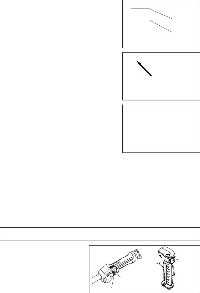
Operation of Throttle Lever
With the throttle lever main unit held by hand (with the lock-off lever pushed), pull the throttle lever and the engine rotation will be increased. Release the throttle lever, and the engine will run idle again.
Release the hand from the throttle lever main unit, and the lock-off lever will return automatically so that the throttle lever will not be pulled by mistake.
Adjustment of Engine ROTATION
When adjusting the engine rotation with the throttle lever opened to the full, turn the throttle control dial. Turn the dial clockwise, and the engine rotation will be reduced. Turn the dial counterclockwise, and the engine rotation will be increased.
ADJUSTMENT OF LOW-SPEED ROTATION (IDLING)
When it is necessary to adjust the low-speed rotation (idling), perform it by the carburetor adjusting screw.
CHECKUP OF LOW-SPEED ROTATION
–Set the low-speed rotation to 3,000 min-1.
If it is necessary to change the rotation speed, regulate the adjusting screw (illustrated on the left), with Phillips screwdriver.
–Turn the adjusting screw to the right, and the engine rotation will increase. Turn the adjusting screw to the left, and the engine rotation will drop.
–The carburetor is generally adjusted before shipment. If it is necessary to readjust it, please contact Authorized Service Agent.
RESHARPENING THE CUTTING TOOL
CAUTION:
The cutting tools mentioned below must only be resharpened by an authorized facility. Manual resharpening will result in imbalances of the cutting tool causing vibrations and damage to the equipment.
–cutter blade
An expert resharpening and balancing service is provided by Authorized Service Agents.
NOTE:
To increase the service life of the cutter blade it may be turned over once, until both cutting edges have become blunt.
NYLON CUTTING HEAD
The nylon cutting head is a dual Petrol Brushcutter head capable of both automatic and bump & feed mechanisms.
The nylon cutting head will automatically feed out the proper length of nylon cord by the changes in centrifugal force caused by increasing or decreasing rpms. However, to cut soft grass more efficiently, bump the nylon cutting head against the ground to feed out extra cord as indicated under operation section.
Operation
–Increase the nylon cutting head speed to approx. 6,000 min-1.
Low speed (under 4,800 min-1) is not suitable, the nylon cord will not feed out properly at low speed.
–The most effective cutting area is shown by the shaded area.
If the nylon cord does not feed out automatically proceed as follows:
1.Release the throttle lever to run the engine idle and then squeeze the throttle lever fully. Repeat this procedure until the nylon cord feeds out to the proper length.
2.If the nylon cord is too short to feed out automatically with the above procedure, bump the knob of the nylon cutting head against the ground to feed out the nylon cord.
3.If the nylon cord does not feed out with procedure 2, rewind/replace the nylon cord by following the procedures described under “Replacing the nylon cord.”
Adjusting screw
Carburetor
Most effective cutting area
Idle speed |
Full speed |
Knob
16

Replacing the nylon cord |
|
|
|
Pull up |
1. Put off cover from housing, pressing two cover locking tabs located |
|
|
|
|
|
|
Cover |
||
oppositely on side of the housing. |
|
|
Locking |
|
|
|
|
Tab |
|
|
|
|
||
|
|
|
|
|
|
Housing Window |
|
|
|
2. Take off tap knob and spool from the housing. |
|
|
|
|
|
|
|
||
Tab knob |
|
Spool |
||
|
|
|||
|
|
|
||
|
|
|
|
|
|
|
|
|
|
3.Put each one end of two cutting lines into each holes at inner most of the slot on one of spool outer flanges. Put the lines into spool gutters through each slit on the flanges.
4.Wind the lines up firmly to the direction slown by left-hand (LH) arrow on the flange. Do not cross the lines.
5.Wind all but about 100 mm (3-15/16”) of the Cords, leaving the end temporarily hooked through a notch on the side of the spool.
6.Put tap knob onto the housing hub, positioning it can freely move up and down against spring tension. Put the spool into the housing, aligning the teeth on spool and tap knob alternately like gears.
|
|
|
|
|
|
|
|
|
|
|
There is a hole inner |
|
|
|
Slit |
|
|
most of the slit |
|
|
|
|
|
|
|
|
|
|
|
|
|
|
|
|
|
|
|
|
|
|
|
To “LH” direction
Wind tightly
100 mm from notches
Tab knob’s Teeth
Spool’s Teeth
17

7. Put in the cutting lines through the slot of eyelets.
8.Put the cover onto the housing, aligning the tabs on cover and the windows on housing. Make sure the cover is secured exactly to the housing. Outer edge of cover locking tab and outer surface of the housing should be on same circumference.
Cover Locking Tab
Housing
Window
Outer Edge |
Outer |
of Cover |
surface of |
Locking Tab |
Housing |
SERVICING INSTRUCTIONS
CAUTION: Before doing any work on the Petrol Brushcutter, always stop the engine and pull the plug cap off the spark plug (see “checking the spark plug”).
Always wear protective gloves!
To ensure a long service life and to avoid any damage to the equipment, the following servicing operations should be performed at regular intervals.
Daily checkup and maintenance
–Before operation, check the machine for loose screws or missing parts. Pay particular attention to the tightness of the cutter blade or nylon cutting head.
–Before operation, always check for clogging of the cooling air passage and the cylinder fins. Clean them if necessary.
–Perform the following work daily after use:
•Clean the Petrol Brushcutter externally and inspect for damage.
•Clean the air filter. When working under extremely dusty conditions, clean the filter the severall times a day.
•Check the blade or the nylon cutting head for damage and make sure it is firmly mounted.
•Check that there is sufficient difference between idling and engagement speed to ensure that the cutting tool is at a standstill while the engine is idling (if necessary reduce idling speed).
If under idling conditions the tool should still continue to run, consult your nearest Authorized Service Agent.
–Check the functioning of the I-O switch, the lock-off lever, the control lever, and the Lock button.
REPLACEMENT OF ENGINE OIL
Deteriorated engine oil will shorten the life of the sliding and rotating parts to a great extent. Be sure to check the period and quantity of replacement.
ATTENTION: In general, the engine main unit and engine oil still remain hot just after the engine is stopped. In replacement of oil, confirm that the engine main unit and engine oil are sufficiently cooled down. Otherwise, there may remain a risk of scald.
Note: If the oil filled above the limit, it may be contaminated or may catch fire with white smoke.
Interval of replacement: Initially, every 20 operating hours, and subsequently every 50 operating hours Recommended oil: SAE10W-30 oil of API Classification SF Class or higher (4-stroke engine oil for automobile)
18

In replacement, perform the following procedure.
1)Confirm that the tank cap is tightened securely.
2)Detach the oil gauge.
Keep the oil gauge free from dust or dirt.
3) Place waste or paper near the oil refill port.
4)Detach the oil gauge, and drain oil, tilting the main unit toward the oil refill port.
Drain oil in a container for orderly disposal.
5)Keep the engine level, and feed new oil up to the edge of the oil refill port. In refill, use a lubricant refill container.
6)After refill, securely tighten the oil gauge. Insufficient tightening of the oil gauge will lead to oil leakage.
Fuel tank cap
Oil gauge
Waste or paper
POINTS ON OIL
–Never discard replaced engine oil in garbage, earth or sewage ditch. Disposal of oil is regulated by law. In disposal, always follow the relevant laws and regulations. For any points remaining unknown, contact Authorized Service Agent.
–Oil will deteriorate even when it is kept unused. Perform inspection and replacement at regular intervals (replace with new oil every 6 months).
19

CLEANING OF AIR CLEANER
DANGER: INFLAMMABLES STRICTLY PROHIBITED
Interval of Cleaning and Inspection: Daily (every 10 operating hours)
–Turn the choke lever to the full close side, and keep the carburetor off from dust or dirt.
–Remove the air cleaner cover-fixing bolts.
–Pull the cover lower side and detach the air cleaner cover.
–If oil adheres to the element (sponge), squeeze it firmly.
–For heavy contamination:
1)Remove the element (sponge), immerse it in warm water or in waterdiluted neutral detergent, and dry it completely.
2)Clean the element (felt) with gasoline, and dry it completely.
–Before attaching the element, be sure to dry it completely. Insufficient drying of the element may lead to difficult startup.
–Wipe out with waste cloth, oil adhering around the air cleaner cover and plate breather.
–Immediately after cleaning is finished, attach the cleaner cover and tighten it with fixing bolts. (In remounting, first place the upper claw, and then the lower claw.)
Points in handling air cleaner element
–Clean the element several times a day, if excessive dust adheres to it.
–If operation continues with the element remaining not cleared of oil, oil in the air cleaner may fall outside, resulting in oil contamination.
CHECKING THE SPARK PLUG
–Only use the supplied universal wrench to remove or to install the spark plug.
–The gap between the two electrodes of the spark plug should be 0.7 - 0.8 mm (0.028”-0.032”). If the gap is too wide or too narrow, adjust it. If the spark plug is clogged or contaminated, clean it thoroughly or replace it.
CAUTION: Never touch the spark plug connector while the engine is running (danger of high voltage electric shock).
SUPPLY OF GREASE TO GEAR CASE
–Supply grease (Shell Alvania 2 or equivalent) to the gear case through the grease hole every 30 hours. (Genuine MAKITA grease may be purchased from your MAKITA dealer.)
Plate
Element (sponge)
Air cleaner cover
Breather Part
Element (felt)
Fixing bolt
Pick this part and remove the element (felt).
0.7 mm - 0.8 mm (0.028”-0.032”)
Gear case
Grease hole
20
CLEANING OF FUEL FILTER
WARNING: INFLAMMABLES STRICTLY PROHIBITED
Interval of Cleaning and Inspection: Monthly (every 50 operating hours)
Suction head in the fuel tank
–The fuel filter (1) of the suction head is used to filler the fuel required by the carburetor.
–A periodical visual inspection of the fuel filter is to be conducted. For that purpose open the tank cap, use a wire hook and pull out the suction head through the tank opening. Filters found to have hardened, been polluted or clogged up are to be replaced.
–Insufficient fuel supply can result in the admissible maximum speed being exceeded. It is therefore important to replace the fuel filter at least quarterly to ensure satisfactory fuel supply to the carburetor.
Fuel filter (1)
House clamp
Fuel pipe
REPLACEMENT OF FUEL PIPE
CAUTION: INFLAMMABLES STRICTLY PROHIBITED
Interval of Cleaning and Inspection: Daily (every 10 operating hours) Replacement: Annually (every 200 operating hours)
Replace the fuel pipe every year, regardless of operating frequency. Fuel leakage may lead to fire.
If any leakage is detected during inspection, replace the oil pipe immediately.
INSPECTION OF BOLTS, NUTS AND SCREWS
–Retighten loose bolts, nuts, etc.
–Check for fuel and oil leakage.
–Replace damaged parts with new ones for safety operation.
Fuel pipe
CLEANING OF PARTS
–Keep the engine always clean.
–Keep the cylinder fins free of dust or dirt. Dust or dirt adhering to the fins will cause piston seizure.
REPLACEMENT OF GASKETS AND PACKINGS
In reassembling after the engine is dismounted, be sure to replace the gaskets and packings with new ones.
Any maintenance of adjustment work that is not included and described in this manual is only to be performed by Authorized Service Agents.
21

STORAGE
WARNING: When draining the fuel, be sure to stop the engine and confirm that the engine cools down.
Just after stopping the engine, it may still hot with possibility of burns, inflammability and fire.
ATTENTION: When the machine is kept out of operation for a long time, drain up all fuel from the fuel tank and carburetor, and keep it at a dry and clean place.
–Drain up fuel from the fuel tank and carburetor according to the following procedure:
1)Remove the fuel tank cap, and drain fuel completely.
If there is any foreign matter remaining in the fuel tank, remove it completely.
2)Pull out the fuel filter from the refill port using a wire.
3)Push the primer pump until fuel is drained from there, and drain fuel coming into the fuel tank.
4)Reset the filter to the fuel tank, and securely tighten the fuel tank cap.
5)Then, continue to operate the engine until it stops.
–Remove the spark plug, and drip several drops of engine oil through the spark plug hole.
–Gently pull the starter handle so that engine oil will spread over the engine, and attach the spark plug.
–Attach the cover to the cutter blade.
–During storage, keep the rod horizontal or keep the machine upright with the blade edge oriented upward. (In this case, pay full attention to prevent the machine from falling.)
Never store the machine with the cutter blade edge oriented downward. Lubricating oil may spill out.
–Keep the drained fuel in a special container in a well-ventilated shade.
Attention after long-time storage
–Before startup after long-time shutdown, be sure to replace oil (refer to P 17). Oil will deteriorate while the machine is kept out of operation.
Fault location
Fault |
System |
Observation |
Cause |
|
|
|
|
Engine not starting or with |
Ignition system |
Ignition spark O.K. |
Fault in fuel supply or compression system, mechanical |
difficulty |
|
|
defect |
|
|
No ignition spark |
STOP-switch operated, wiring fault or short circuit, spark |
|
|
|
plug or connector defective, ignition module faulty |
|
Fuel supply |
Fuel tank filled |
Incorrect choke position, carburetor defective, fuel supply |
|
|
|
line bent or blocked, fuel dirty |
|
Compression |
No compression when |
Cylinder bottom gasket defective, crankshaft seals |
|
|
pulled over |
damaged, cylinder or piston rings defective or improper |
|
|
|
sealing of spark plug |
|
Mechanical fault |
Starter not engaging |
Broken starter spring, broken parts inside of the engine |
Warm start problems |
|
Tank filled ignition spark |
Carburetor contaminated, have it cleaned |
|
|
existing |
|
Engine starts but dies |
Fuel supply |
Tank filled |
Incorrect idling adjustment, carburetor contaminated |
|
|
|
Fuel tank vent defective, fuel supply line interrupted, |
|
|
|
cable or STOP-switch faulty |
Insufficient performance |
Several systems may |
Engine idling poor |
Air filter contaminated, carburetor contaminated, muffler |
|
simultaneously be |
|
clogged, exhaust duct in the cylinder clogged |
|
affected |
|
|
|
|
|
|
22

Operating time |
Before |
After |
Daily |
50h |
Shutdown/ |
Corres- |
Item |
operation |
lubrication |
30h |
200h |
ponding P |
|
(10h) |
|
rest |
||||
Engine oil |
Inspect/clean |
|
|
|
|
12 |
Replace |
|
|
*1 |
|
18 |
|
|
|
|
|
|||
Tightening parts |
Inspect |
|
|
|
|
21 |
(bolt, nut) |
|
|
|
|
||
|
|
|
|
|
|
|
Fuel tank |
Clean/inspect |
|
|
|
|
— |
Drain fuel |
|
|
|
*3 |
22 |
|
|
|
|
|
|||
Throttle lever |
Check function |
|
|
|
|
— |
Stop switch |
Check function |
|
|
|
|
15 |
Cutting blade |
Inspect |
|
|
|
|
10 |
Low-speed rotation |
Inspect/adjust |
|
|
|
|
16 |
Air cleaner |
Clean |
|
|
|
|
20 |
Ignition plug |
Inspect |
|
|
|
|
20 |
Cooling air duct |
Clean/inspect |
|
|
|
|
21 |
Fuel pipe |
Inspect |
|
|
|
|
21 |
Replace |
|
|
|
*2 |
— |
|
|
|
|
|
|||
Gear-case grease |
Refill |
|
|
|
|
20 |
Fuel filter |
Clean/replace |
|
|
|
|
21 |
Clearance between air intake |
Adjust |
|
|
|
*2 |
— |
valve and air discharge valve |
|
|
|
|
|
|
Oil tube |
Inspect |
|
|
|
*2 |
|
Engine overhaul |
|
|
|
|
*2 |
— |
Carburetor |
Drain fuel |
|
|
|
*3 |
22 |
*1 Perform initial replacement after 20h operation.
*2 For the 200 operating hour inspection, request Authorized Service Agent or a machine shop. *3 After emptying the fuel tank, continue to run the engine and drain fuel in the carburetor.
23

TROUBLESHOOTING
Before making a request for repairs, check a trouble for yourself. If any abnormality is found, control your machine according to the description of this manual. Never tamper or dismount any part contrary to the description. For repairs, contact Authorized Service Agent or local dealership.
|
State of abnormality |
Probable cause (malfunction) |
Remedy |
|||
|
|
|
|
|
|
|
|
|
|
|
Failure to operate primer pump |
Push 7 to 10 times |
|
|
|
|
|
|
|
|
|
|
|
|
Low pulling speed of starter rope |
Pull strongly |
|
|
|
|
|
|
|
|
|
|
|
|
Lack of fuel |
Feed fuel |
|
|
|
|
|
|
|
|
|
|
|
|
Clogged fuel filter |
Clean |
|
|
|
|
|
|
|
|
|
|
|
|
Broken fuel tube |
Straighten fuel tube |
|
|
|
|
|
|
|
|
|
|
|
|
Deteriorated fuel |
Deteriorated fuel makes starting more difficult. |
|
|
|
|
|
|
Replace with new one. (Recommended |
|
|
|
|
|
|
replacement: 1 month) |
|
|
|
|
|
|
|
|
|
|
|
|
Excessive suction of fuel |
Set throttle lever from medium speed to high |
|
|
|
|
|
|
speed, and pull starter handle until engine |
|
|
|
|
|
|
starts. Once engine starts, cutter blade |
|
Engine does not start |
|
starts rotating. Pay full attention to cutter |
||||
|
|
|
|
|
blade. |
|
|
|
|
|
|
If engine will not start still, remove spark plug, |
|
|
|
|
|
|
make electrode dry, and reassemble them as |
|
|
|
|
|
|
they originally are. Then, start as specified. |
|
|
|
|
|
|
|
|
|
|
|
|
Detached plug cap |
Attach securely |
|
|
|
|
|
|
|
|
|
|
|
|
Contaminated spark plug |
Clean |
|
|
|
|
|
|
|
|
|
|
|
|
Abnormal clearance of spark plug |
Adjust clearance |
|
|
|
|
|
|
|
|
|
|
|
|
Other abnormality of spark plug |
Replace |
|
|
|
|
|
|
|
|
|
|
|
|
Abnormal carburetor |
Make request for inspection and maintenance. |
|
|
|
|
|
|
|
|
|
|
|
|
Starter rope cannot be pulled |
Make request for inspection and maintenance. |
|
|
|
|
|
|
|
|
|
|
|
|
Abnormal drive system |
Make request for inspection and maintenance. |
|
|
|
|
|
|
|
|
|
|
|
|
Insufficient warm-up |
Perform warm-up operation |
|
|
|
|
|
|
|
|
|
|
|
|
Choke lever is set to “CLOSE” although |
Set to “OPEN” |
|
|
|
|
|
engine is warmed up. |
||
|
|
|
|
|
||
Engine stops soon |
|
|
||||
Clogged fuel filter |
Clean |
|||||
Engine speed does not increase |
||||||
|
|
|||||
Contaminated or clogged air cleaner |
Clean |
|||||
|
|
|
|
|||
|
|
|
|
|
|
|
|
|
|
|
Abnormal carburetor |
Make request for inspection and maintenance. |
|
|
|
|
|
|
|
|
|
|
|
|
Abnormal drive system |
Make request for inspection and maintenance. |
|
|
|
|
|
|
|
|
Cutter blade does not rotate |
Loosened cutter blade-tightening nut |
Tighten securely |
||||
|
|
|
|
|
|
|
|
|
|
|
Twigs caught by cutter blade or dispersion- |
Remove foreign matter |
|
|
|
|
|
preventing cover. |
||
|
|
|
|
|
||
|
Stop engine immediately |
|
|
|
||
Abnormal drive system |
Make request for inspection and maintenance. |
|||||
|
|
|
|
|||
|
|
|
|
|||
|
|
|
|
|
|
|
Main unit vibrates abnormally |
Broken, bent or worn cutter blade |
Replace cutter blade |
||||
|
|
|
|
|
|
|
|
|
|
|
Loosened cutter blade-tightening nut |
Tighten securely |
|
|
|
|
|
|
|
|
|
|
|
|
Shifted convex part of cutter blade and cutter |
Attach securely |
|
|
|
|
|
blade support fitting. |
||
|
|
|
|
|
||
|
Stop engine immediately |
|
|
|
||
Abnormal drive system |
Make request for inspection and maintenance. |
|||||
|
|
|
|
|||
|
|
|
|
|||
|
|
|
|
|
|
|
Cutter blade does not stop immediately |
High idling rotation |
Adjust |
||||
|
|
|
|
Detached throttle wire |
Attach securely |
|
|
|
|
|
|||
|
Stop engine immediately |
|
|
|
||
Abnormal drive system |
Make request for inspection and maintenance. |
|||||
|
|
|
|
|||
|
|
|
|
|
|
|
Engine does not stop |
Detached connector |
Attach securely |
||||
|
|
|
|
|
|
|
|
|
|
|
Abnormal electric system |
Make request for inspection and maintenance. |
|
|
|
|
|
|||
|
Run engine at idling, and set choke lever |
|
|
|
||
|
to CLOSE |
|
|
|
||
|
|
|
|
|
|
|
|
|
|
|
|
|
|
When the engine does not start after warm-up operation:
If there is no abnormality found for the check items, open the throttle by about 1/3 and start the engine.
24
Français |
(Instructions d’origine) |
Merci pour votre achat de cette débroussailleuse thermique de MAKITA. Nous sommes ravis de vous proposer la débroussailleuse thermique de MAKITA, résultat d’un long programme de développement et de nombreuses années d’expérience et de connaissances.
Veuillez lire ce livret qui explique en détails les nombreuses caractéristiques qui en font un outil d’une performance exceptionnelle. Il vous aidera à obtenir le meilleur résultat possible avec votre débroussailleuse thermique de MAKITA.
Table des matières |
Page |
Symboles..................................................................... |
25 |
Consignes de sécurité................................................. |
26 |
Données techniques ................................................... |
30 |
Nomenclature des pièces............................................ |
31 |
Montage de la poignée................................................ |
32 |
Montage du dispositif de protection............................. |
33 |
Montage du couteau ou de la tête à fil en nylon.......... |
34 |
Avant de commencer................................................... |
35 |
Maniement correct de la machine ............................... |
37 |
Avertissement de fonctionnement et comment |
|
l’arrêter ........................................................................ |
37 |
Réaffûtage du couteau ................................................ |
39 |
Instructions d’entretien ................................................ |
41 |
Entreposage ................................................................ |
45 |
SYMBOLES
Le mode d’emploi contient les symboles suivants.
Lisez le mode d’emploi et suivez les avertissements et les précautions de sécurité !
Usez d’attention et de soins tout particulier !
Interdit !
Restez à distance !
Danger d’objets volants !
Ne fumez pas !
Pas de flammes nues !
Portez des gants de protection !
Portez des bottes de sécurité avec des semelles antidérapantes.
Les bottes de sécurité à doigts de pieds métalliques sont recommandées !
Eloignez les personnes et les animaux du lieu de travail !
Portez un casque protecteur, des lunettes de protection et des protège-oreilles !
Vitesse d’outil maximale autorisée
Carburant (Essence)
Démarrage manuel du moteur
Arrêt d’urgence
Premier secours
SOUS TENSION/DEMARRAGE
HORS TENSION/ARRET
Choc en retour !
25

CONSIGNES DE SÉCURITÉ
Instructions générales
–Lisez ce manuel d’instructions pour vous familiariser avec l’utilisation de l’appareil. Sans ces informations, vous risquez de vous mettre en danger ou de blesser d’autres personnes à cause d’une utilisation incorrecte.
–Il est préférable de ne prêter l’appareil qu’à des personnes expérimentées. Prêtez-leur systématiquement le manuel d’instructions.
–Veuillez d’abord solliciter des instructions de base auprès du vendeur, afin de vous familiariser avec le fonctionnement des débroussailleuses.
–Les enfants et les adolescents de moins de 18 ans ne doivent pas utiliser cet appareil. Les personnes de plus de 16 ans peuvent l’utiliser à des fins de formation, mais sous la supervision d’un formateur agréé.
–Faites preuve d’une extrême vigilance et attention.
–Utilisez l’appareil uniquement si vous êtes en bonne condition physique. Effectuez tout le travail avec calme et prudence. Vous êtes responsable par rapport aux autres personnes.
–N’utilisez jamais cet appareil après avoir consommé de l’alcool ou de la drogue, ou bien si vous vous sentez fatigué ou malade.
–Les lois en vigueur peuvent restreindre l’utilisation de l’outil.
Utilisation prévue de l’outil
–Cet appareil est destiné uniquement à couper le gazon, les mauvaises herbes, les buissons et les sous-bois. Il ne doit pas être utilisé à d’autres fins, telles que la taille des bordures ou des haies, car cela comporte un risque de blessure.
Équipement de protection individuelle
–Les vêtements que vous portez doivent être fonctionnels et adaptés, c’est-à-dire qu’ils doivent être près du corps, sans pour autant gêner vos mouvements. Ne portez pas de bijoux ou de vêtements qui pourraient s’emmêler dans les taillis ou les petits arbustes.
–L’équipement de protection suivant ainsi que les vêtements de protection doivent être utilisés afin d’éviter des blessures au pied, à la main, aux yeux et à la tête ainsi que pour protéger votre ouïe durant l’utilisation.
–Portez toujours un casque en cas de risque de chute d’objets. Le casque de protection (1) doit être vérifié à intervalles réguliers pour parer à d’éventuels dommages et il doit être remplacé au plus tard tous les 5 ans. N’utilisez que des casques de protection agréés.
–La visière (2) du casque (ou alternativement les lunettes) protège le visage des débris et des pierres qui volent. Pendant l’utilisation, portez toujours des lunettes de protection ou une visière pour éviter toute blessure aux yeux.
–Portez un équipement de protection antibruit adéquat afin d’éviter toute perte auditive (coquilles antibruit (3), bouchons d’oreille etc.).
–Les vêtements de travail (4) protègent contre les débris et les pierres qui volent.
Nous vous recommandons fortement de porter des vêtements de travail.
–Les gants (5) font partie de l’équipement prescrit et doivent toujours être portés pendant l’utilisation.
–Lorsque vous utilisez l’appareil, portez toujours des chaussures robustes (6) équipées de semelles anti-dérapantes. Elles vous protégeront des blessures éventuelles et vous assureront une bonne stabilité.
Démarrage de la débroussailleuse
–Éloignez les personnes et les enfants à une distance minimum de 15 mètres du lieu de travail et faites attention aux animaux qui pourraient se trouver à proximité.
–Avant l’utilisation, vérifiez toujours que l’appareil ne présente aucun danger :
Vérifiez la sécurité de l’outil de coupe, la maniabilité du levier d’accélération ainsi que le bon fonctionnement du verrouillage du levier d’accélération.
–La rotation du dispositif de coupe au repos est interdite. En cas de doute, vérifiez le réglage avec votre revendeur. Vérifiez que les poignées sont propres et sèches et que l’interrupteur marche/arrêt fonctionne correctement.
Illustration
15 mètres
26
Ne démarrez la débroussailleuse qu’en conformité avec les instructions.
–Ne démarrez pas le moteur selon une autre méthode !
–Utilisez la débroussailleuse et les outils uniquement pour les applications spécifiées.
–Ne démarrez le moteur qu’après avoir procédé au montage complet de l’appareil. Le fonctionnement de l’outil n’est autorisé qu’une fois l’ensemble des accessoires fixés !
–Avant de démarrer, assurez-vous que l’outil de coupe n’est pas en contact avec des objets durs tels que des branches, des pierres, etc. et qu’il tournera au démarrage.
–En cas de problème avec le moteur, éteignez-le immédiatement.
–Si l’outil de coupe heurte des pierres ou d’autres objets durs, arrêtez immédiatement le moteur et examinez l’outil de coupe.
–Examinez l’outil de coupe à intervalles réguliers courts pour vous assurer qu’il n’a pas subi de dommages (détection de fissures capillaires à l’aide du test de tapping).
–En cas de chute ou d’impact de l’appareil, vérifiez qu’il est en bon état avant de poursuivre le travail. Vérifiez qu’il n’y a pas de fuite de carburant dans
le circuit d’alimentation, et que les commandes et dispositifs de sécurité fonctionnent correctement. En cas de dommage ou de doute, demandez à un centre d’entretien agréé d’examiner et de réparer l’outil.
–N’utilisez l’appareil qu’avec la bandoulière que vous devez régler correctement avant de mettre la débroussailleuse en marche. Il est très important de régler la bandoulière selon votre taille afin d’éviter toute fatigue supplémentaire pendant l’utilisation. Ne tenez jamais l’outil d’une seule main pendant l’utilisation.
–Tenez toujours la débroussailleuse à deux mains. Assurez-vous toujours d’avoir une bonne stabilité.
–Utilisez l’appareil de façon à éviter d’inhaler les gaz d’échappement. Ne faites jamais tourner le moteur dans une pièce confinée (risque d’intoxication aux gaz). Le monoxyde de carbone est un gaz inodore.
–Éteignez le moteur lorsque vous faites une pause ou laissez l’appareil sans surveillance, et placez-le dans un endroit sûr pour éviter de mettre en danger les autres personnes ou d’endommager l’outil.
–Ne placez jamais la débroussailleuse sur de l’herbe sèche ou des matériaux combustibles.
–Installez toujours le protège-lame de l’outil de coupe approuvé sur l’appareil avant de démarrer le moteur.
Sinon, un contact avec l’outil de coupe pourrait causer de graves blessures.
–Vous devez utiliser toutes les installations protectives et protections fournies avec l’outil durant l’utilisation.
–Ne faites jamais fonctionner le moteur si le pot d’échappement est endommagé.
–Éteignez le moteur durant le transport.
–Lorsque vous transportez l’appareil, fixez toujours le couvercle sur la lame de coupe.
–Pour éviter toute fuite de carburant, assurez-vous que l’appareil est bien fixé lors des transports en voiture.
–Lors du transport, assurez-vous que le réservoir de carburant est complètement vide.
–Lorsque vous déchargez l’appareil du coffre, ne laissez jamais tomber le moteur au sol, car cela risquerait d’endommager le réservoir de carburant.
–Sauf en cas d’urgence, ne laissez jamais tomber l’appareil et ne le jetez pas sur le sol, au risque de l’endommager grièvement.
–Veillez à soulever l’ensemble du matériel du sol lorsque vous le déplacez. Il est très dangereux de traîner le réservoir de carburant : cela risque de créer des fuites de carburant, voire un incendie.
Ravitaillement en carburant
–Lors du ravitaillement en carburant, coupez le moteur, éloignez-le des flammes nues et ne fumez pas.
–Évitez tout contact entre la peau et l’essence. N’inhalez pas les vapeurs de carburant. Portez toujours des gants de protection durant le ravitaillement en carburant. Changez et nettoyez régulièrement les vêtements de protection.
–Veillez à ne pas renverser de carburant ou d’huile, afin d’éviter toute contamination du sol (protection environnementale). Nettoyez immédiatement la débroussailleuse en cas d’écoulement de carburant.
–Évitez tout contact entre vos vêtements et le carburant. Si vous renversez du carburant sur vos vêtements, changez-en immédiatement (pour éviter que vos vêtements ne prennent feu).
–Vérifiez régulièrement le bouchon du réservoir pour vous assurer qu’il est bien fermé et ne fuit pas.
–Serrez soigneusement le bouchon du réservoir de carburant. Déplacez-vous pour démarrer le moteur (éloignez-vous à au moins 3 mètres de l’endroit où vous avez fait le plein).
–Ne faites jamais le plein dans une pièce confinée. Les vapeurs de carburant s’accumulent au niveau du sol (risque d’explosion).
–Transportez et stockez le carburant uniquement dans des récipients agréés. Assurez-vous que les enfants ne peuvent pas accéder au carburant.
•Au repos
•Transport
•Plein d’essence
•Entretien
•Remplacement d’outil
3
27

Mode d’emploi
–N’utilisez l’appareil que si les conditions d’éclairage et de luminosité sont satisfaisantes. En hiver, soyez attentif aux zones glissantes ou mouillées, au verglas et à la neige (risque de glissade). Assurez-vous toujours d’avoir une bonne stabilité.
–Ne coupez jamais à une hauteur supérieure aux épaules.
–Ne montez jamais sur une échelle.
–Ne montez jamais dans un arbre pour procéder à la coupe.
–Ne travaillez jamais sur des surfaces instables.
–Enlevez le sable, les pierres, les clous etc., trouvés à l’intérieur du périmètre de travail.
Des corps étrangers peuvent endommager l’outil de coupe et causer des chocs en retour dangereux.
–Avant de commencer à couper, l’outil de coupe doit avoir atteint sa vitesse de travail maximale.
–En cas d’utilisation de lames métalliques, balancez l’outil régulièrement en demi-cercle de droite à gauche, comme si vous utilisiez une faux.
Si de l’herbe ou des branches sont coincées entre l’outil de coupe et le protège-lame, coupez toujours le moteur avant de procéder au nettoyage. Sinon, la rotation imprévue de la lame pourrait causer de graves blessures.
–Reposez-vous pour éviter toute perte de contrôle due à la fatigue. Il est recommandé de faire une pause de 10 à 20 minutes toutes les heures.
Outils de coupe
–Utilisez un outil de coupe adapté au travail à effectuer.
Les têtes à fil de nylon (têtes de taille à fils) conviennent au taillage du gazon.
Les lames métalliques permettent de couper les mauvaises herbes, les herbes hautes, les buissons, les petits arbustes, les sous-bois, les fourrés et autres végétaux similaires.
N’utilisez jamais d’autres lames, dont les chaînes pivotantes en métal et les lames batteuses. Dans le cas contraire, l’appareil risquerait de blesser grièvement des personnes.
–Lors de l’utilisation de lames métalliques, évitez les « chocs en retour » et préparez-vous toujours à un choc en retour accidentel. Reportez-vous à la section « Choc en retour » et « Prévention des chocs en retour ».
Choc en retour (poussée de lame)
–Le choc en retour (poussée de lame) est une réaction soudaine d’une lame de coupe agrippée ou coincée. Lorsque cela se produit, l’outil est projeté fortement sur le côté ou vers l’opérateur et il peut provoquer des blessures graves.
–Le choc en retour se produit en particulier lorsque vous appliquez le segment de lame entre 12 heures et 2 heures sur des corps solides, des buissons ou des arbres de 3 cm de diamètre ou plus.
–Pour éviter les chocs en retour :
•Appliquez le segment entre 8 heures et 11 heures ;
•N’appliquez jamais le segment entre 12 heures et 2 heures ;
•N’appliquez jamais le segment entre 11 heures et 12 heures et entre 2 heures et 5 heures, sauf si vous avez reçu une bonne formation et êtes expérimenté(e), et ceci à vos propres risques ;
•N’utilisez jamais les lames de coupe près d’éléments solides, tels que des barrières, des murs, des troncs d’arbres et des pierres ;
•N’utilisez jamais les lames de coupe verticalement pour tailler des bordures ou des haies.
Vibrations
–Les personnes souffrant de troubles circulatoires peuvent subir des blessures au niveau des vaisseaux sanguins ou du système nerveux si elles sont exposées à des vibrations excessives. Les vibrations peuvent entraîner
les symptômes suivants aux doigts, mains ou poignets : engourdissement, picotements, douleur, sensation lancinante, altération de la couleur ou de l’aspect de la peau. Si l’un ou l’autre de ces symptômes apparaît, consultez un médecin !
–Afin de réduire le risque de syndrome des vibrations du système main-bras, gardez vos mains au chaud et maintenez correctement l’appareil et ses accessoires.
Instructions d’entretien
–L’entretien de votre appareil doit être effectué par l’un de nos centres d’entretien agréés et seules des pièces de rechange authentiques doivent être utilisées. Une réparation incorrecte et un entretien défectueux peuvent réduire la durée de vie de l’appareil et accroître le risque d’accidents.
–Avant de commencer à utiliser l’outil, vérifiez son état, notamment l’outil de coupe des dispositifs de protection et la bandoulière. Examinez également avec une attention toute particulière les lames de coupe, qui doivent être bien affûtées.
–Coupez le moteur et retirez le connecteur de bougies lorsque vous remplacez ou aiguisez les dispositifs de coupe et lorsque vous nettoyez la lame de coupe ou le dispositif de coupe.
Attention : Choc en retour
Ilustration
Ilustration
28

Ne redressez et ne soudez jamais des outils de coupe endommagés.
–Respectez l’environnement. Pour réduire la pollution et les émissions sonores, évitez tout fonctionnement inutile du papillon des gaz. Réglez correctement le carburateur.
–Nettoyez régulièrement l’appareil et vérifiez que l’ensemble des vis et des écrous est bien serré.
–Ne procédez jamais à l’entretien de l’appareil et ne le rangez pas à proximité de flammes nues.
–Rangez toujours l’appareil dans une pièce fermée, après avoir vidé le réservoir de carburant.
–Lors du nettoyage, de l’entretien et du stockage de l’appareil, fixez toujours le couvercle à la lame de coupe.
Respectez les instructions de prévention des accidents publiées par les associations professionnelles concernées et les compagnies d’assurance.
N’effectuez aucune modification sur l’appareil, au risque de mettre votre sécurité en danger.
L’exécution de l’entretien ou des réparations par l’utilisateur est limitée aux activités décrites dans le manuel d’instructions. Toute autre tâche doit être réalisée par un agent d’entretien agréé. N’utilisez que des pièces de rechange et des accessoires d’origine fournis par MAKITA. L’utilisation d’accessoires ou d’outils non agréés augmente les risques d’accident.
MAKITA n’acceptera aucune responsabilité pour des accidents ou des dommages causés par l’utilisation d’outils de coupe, de dispositifs de fixation d’outils de coupe ou d’accessoires.
Premiers secours
En cas d’accident, assurez-vous qu’une mallette de premier secours se trouve à proximité des opérations de coupe. Remplacez immédiatement tout article pris dans la mallette de premier secours.
Lorsque vous demandez de l’aide, veuillez fournir les renseignements suivants :
–Lieu de l’accident
–Ce qui s’est passé
–Nombre de personnes blessées
–Types de blessures
–Votre nom
Pour les pays d’Europe uniquement
Déclaration de conformité CE
Nous, Makita Corporation, en tant que fabricant responsable, déclarons que la ou les machines Makita suivantes :
Nom de la machine : Débroussailleuse Thermique N° de modèle/Type : EBH341U, EBH341L
Spécifications : reportez-vous au tableau « DONNÉES TECHNIQUES » sont fabriquées en série et
sont conformes aux directives européennes suivantes :
2000/14/CE, 2006/42/CE
et sont produites conformément aux normes ou documents de normalisation suivants : EN ISO 11806-1
La documentation technique est disponible auprès de : Makita International Europe Ltd., Technical Department,
Michigan Drive, Tongwell, Milton Keynes, Bucks MK15 8JD, Angleterre
La procédure d’évaluation de la conformité requise par la directive 2000/14/CE est conforme à l’annexe V. Niveau de puissance sonore mesurée : 109,7 dB
Niveau de puissance sonore garantie : 111 dB
31. 8. 2009
Tomoyasu Kato
Directeur
Makita Corporation
3-11-8, Sumiyoshi-cho,
Anjo, Aichi, JAPAN
29

DONNÉES TECHNIQUES DE L’EBH341U, EBH341L
|
|
Modèle |
|
EBH341U |
|
EBH341L |
|
|
|
|
|
|
|
||
|
|
|
Poignée de vélo |
|
Poignée fermée |
||
|
|
|
|
|
|
||
|
|
|
|
|
|
|
|
Dimensions : longueur x largeur x hauteur (sans la lame de |
mm |
1 810 x 620 x 500 |
|
1 810 x 330 x 275 |
|||
coupe) |
|
|
|
||||
|
|
|
|
|
|
||
|
|
|
|
|
|
|
|
Masse (sans la protection plastique et la lame de coupe) |
kg |
7,1 |
|
6,7 |
|||
|
|
|
|
|
|
|
|
Volume (réservoir d’essence) |
|
L |
|
0,65 |
|||
|
|
|
|
|
|
|
|
Volume (réservoir d’huile) |
|
L |
|
0,1 |
|||
|
|
|
|
|
|
|
|
Déplacement du moteur |
|
cm3 |
|
33,5 |
|||
Performance du moteur maximum |
ISO8893 |
kw |
1,07 à 7 000 min-1 |
||||
|
|
|
|
|
|
|
|
Fréquence maximale de rotation du moteur |
min-1 |
|
6 850 |
||||
Vitesse du moteur à la vitesse de la fréquence de rotation max. |
min-1 |
|
10 000 |
||||
recommandée |
|
|
|
||||
|
|
|
|
|
|
||
|
|
|
|
|
|
|
|
Consommation d’essence à la performance max. du moteur |
kg/h |
|
0,458 |
||||
ISO8893 |
|
|
|
||||
|
|
|
|
|
|
||
|
|
|
|
|
|
|
|
Consommation d’essence spécifique à la performance max. du |
g/kwh |
|
426 |
||||
moteur |
|
|
|
||||
|
|
|
|
|
|
||
|
|
|
|
|
|
|
|
Vitesse du moteur au ralenti |
|
min-1 |
|
3 000 |
|||
Vitesse d’engagement de l’engrenage |
|
min-1 |
|
4 100 |
|||
Carburator (Diaphragme - carburator) |
|
type |
|
WALBRO WYL |
|||
|
|
|
|
|
|
||
Système d’allumage |
|
type |
Allumage à semi-conducteur |
||||
|
|
|
|
|
|
|
|
Bougie d’allumage |
|
type |
|
NGK CMR4A |
|||
|
|
|
|
|
|
|
|
Ecart d’électrode |
|
|
mm |
|
0,7 - 0,8 |
||
|
|
|
|
|
|
|
|
|
|
Poignée droite |
ahv eq |
m/s2 |
3,3 |
|
6,1 |
Vibration selon |
|
(prise arrière) |
Incertitude K |
m/s2 |
0,70 |
|
2,0 |
la norme ISO |
|
|
|
|
|
|
|
|
|
ahv eq |
m/s2 |
2,5 |
|
7,4 |
|
22867 |
|
Poignée gauche |
|
||||
|
|
(prise avant) |
Incertitude K |
m/s2 |
1,26 |
|
0,63 |
Moyenne du niveau de pression |
LPA eq |
dBA |
|
98,2 |
|||
acoustique selon la norme ISO |
|
|
|
|
|
||
Incertitude K |
dBA |
|
2,1 |
||||
22868 |
|
|
|
||||
|
|
|
|
|
|
|
|
|
|
|
|
|
|||
Moyenne du niveau de puissance |
LWA eq |
dBA |
|
106,7 |
|||
acoustique selon la norme ISO |
|
|
|
|
|
||
Incertitude K |
dBA |
|
1,3 |
||||
22868 |
|
|
|
||||
|
|
|
|
|
|
|
|
|
|
|
|
|
|||
Carburant |
|
|
|
Essence automobile |
|||
|
|
|
|
|
|
||
Huile du moteur |
|
|
|
Huile SAE 10W-30 de classe API, |
|||
|
|
|
Classe SF ou supérieure (moteur 4 temps pour automobile) |
||||
|
|
|
|
|
|||
|
|
|
|
||||
Outils de coupe (diamètre couteau) |
|
mm |
305 (avec trois lames) |
||||
|
|
|
|
|
|||
Rapport de vitesse |
|
|
|
13/19 |
|||
|
|
|
|
|
|
|
|
30
 Loading...