


Amana ACS4140BB, ACS4140BW, DF454670, DF454677, MER4326AAA Installation Instructions
...INSTALLER: LEAVE THESE INSTRUCTIONS WITH THE APPLIANCE
INSTALLATION MANUAL
Electric 30-inch Free-standing,
Slide-in & Drop-in Ranges
PLEASE KEEP THIS MANUAL FOR FUTURE REFERENCE
THE MANUAL IS INTENDED TO ASSIST IN THE INITIAL INSTALLATION AND ADJUSTMENTS OF THE RANGE.
SPECIAL WARNING
Only qualified personnel should install or service this range.
Read “Safety Instructions” in the Use & Care book before using range.
Improper installation, adjustment, alteration, service, maintenance or use of range can result in serious injury or property damage.
CLEARANCE DIMENSIONS
For complete information in regard to installation of free-standing, drop-in and slide-in ranges, see figures 1 through 4 on pages 2, 3 and 4. For SAFETY CONSIDERATIONS do not install a range in any combustible cabinetry which is not in accord with the installation clearances shown in figure 1.
CAUTION: Some cabinets and building materials are not designed to withstand the heat produced by the normal safe operation of a listed appliance. Discoloration or damage, such as delamination, may occur.
Your range may not be equipped with some of the features referred to in this manual.
8101P371-60
(10-2000-00)
MOBILE HOMES
The installation of a range designed for mobile home installation must conform with the Manufactured Home Construction and Safety Standard, Title 24 CFR, Part 3280 (formerly the Federal Standard for Mobile Home Construction and Safety, Title 24 HUD, Part 280) or, when such standard is not applicable, the Standard for Manufactured Home Installations 1982 (Manufactured Home Sites, Communities and Set-Ups), ANSI A225.1-latest edition, or with local codes.
LOCATING THE RANGE
Place range in a well lit area. Do not set range over holes in the floor or other locations where it may be subject to strong drafts. Any opening in the wall behind the range and in the floor under the range should be sealed. Make sure the flow of combustion or ventilation air is not obstructed.
INSTALLATION DRAWINGS
IMPORTANT
PLEASE KEEP FOR THE USE OF THE LOCAL ELECTRICAL INSPECTOR.
4
3
1
“A”
2
FIGURE 1
“A” = 30 inches minimum clearance between the top of the cooking surface and the bottom of an unprotected wood or metal cabinet, or “A” = 24 inches minimum when bottom of wood or metal cabinet is protected by not less than 1/4-inch thick flame-retardant millboard covered with not less than No. 28 MSG sheet steel, 0.015-inch thick stainless steel, 0.024-inch thick aluminum, or 0.020-inch thick copper.
To eliminate the risk of burns or fire by reaching over heated surface units, cabinet storage space located above the surface units should be avoided. If cabinet storage is to be provided, the risk can be reduced by installing a range hood that projects horizontally a minimum of 5 inches beyond the bottom of the cabinets.
FIGURE 1
1, 2, 3 - COMBUSTIBLE BUILDING WALLS. 4 - COMBUSTIBLE WALL CABINET.
A free-standing range may be installed adjacent to (0² from) combustible walls 1, 2 & 3.
A slide-in and drop-in range may be installed adjacent to (0² from) combustible walls 2 & 3. The rear wall clearance will be determined by cabinet cut-out depth shown in illustrations on pages 3 and 4.
-2-

FREE-STANDING
FIGURE 2
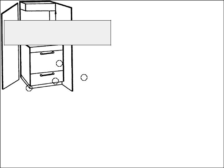
SLIDE-IN
*23 |
1/4² |
30² |
|
CUT DEPTH |
|||
|
|||
BEFORE ATTEMPTING |
|
|
|
INSTALLATION, ADJUST |
5 1/2² |
5 1/2² |
|
RANGE LEVELING LEGS |
|||
TO ACCOMMODATE |
|
|
|
THIS DIMENSION. |
10² |
|
|
36² COUNTER TOP HEIGHT
CAUTION:
SOME WHITE EUROPEAN STYLE CABINETS ARE EQUIPPED WITH DELICATE WHITE VINYL DRAWER AND DOOR FRONTS. THE VINYL MAY NOT BE DESIGNED TO WITHSTAND THE HEAT PRODUCED BY THE NORMAL SAFE OPERATION OF A SELF-CLEAN RANGE. DISCOLORATION OR DELAMINATION MAY OCCUR. TO AVOID POSSIBLE DAMAGE, WE RECOMMEND INCREASING THE 30² CABINET OPENING TO 31 1/4² MINIMUM AND USING HEAT SHIELD KIT-CABKIT V. THE COUNTERTOP CUT-OUT MUST REMAIN 30².
NOTE:
ON CABINET TOPS WITH
FORMED FRONT EDGE, SHAVE
RAISED SECTION TO CLEAR TOP.
PROVIDE FOR 120/208, 120/240 VOLT OUTLET PER APPLICABLE CORD IN THIS AREA.
23 5/8² MIN. |
||
FLAT |
25² MINIMUM |
|
AREA |
||
COUNTER |
||
|
||
|
TOP DEPTH |
|
24² CABINET |
|
|
DEPTH |
|
|
FIGURE 3
* When replacing an existing unit, a maximum of 23 1/2² is acceptable. If the cut depth exceeds 23 1/2², use filler kit (K70 Fill).
-3-
 Loading...