


INSTALLATION INSTRUCTIONS
20" (50.8 CM) FREESTANDING ELECTRIC RANGE
with Standard Clean Oven
Table of Contents
RANGE SAFETY ............................................................................. |
2 |
Install Anti-Tip Bracket................................................................. |
6 |
INSTALLATION REQUIREMENTS ................................................ |
3 |
Electrical Connection ................................................................... |
7 |
Tools and Parts ............................................................................ |
3 |
Verify Anti-Tip Bracket Is Installed and Engaged...................... |
11 |
Location Requirements................................................................ |
3 |
Level Range................................................................................ |
12 |
Electrical Requirements ............................................................... |
5 |
Complete Installation ................................................................. |
12 |
INSTALLATION INSTRUCTIONS .................................................. |
6 |
Check Operation........................................................................ |
12 |
Unpack Range.............................................................................. |
6 |
|
|
|
|
|
|
IMPORTANT:
Save for local electrical inspector's use.
W10459122A
RANGE SAFETY
Your safety and the safety of others are very important.
We have provided many important safety messages in this manual and on your appliance. Always read and obey all safety messages.
This is the safety alert symbol.
This symbol alerts you to potential hazards that can kill or hurt you and others.
All safety messages will follow the safety alert symbol and either the word “DANGER” or “WARNING.” These words mean:
 DANGER
 WARNING
You can be killed or seriously injured if you don't immediately follow instructions.
You can be killed or seriously injured if you don't follow instructions.
All safety messages will tell you what the potential hazard is, tell you how to reduce the chance of injury, and tell you what can happen if the instructions are not followed.
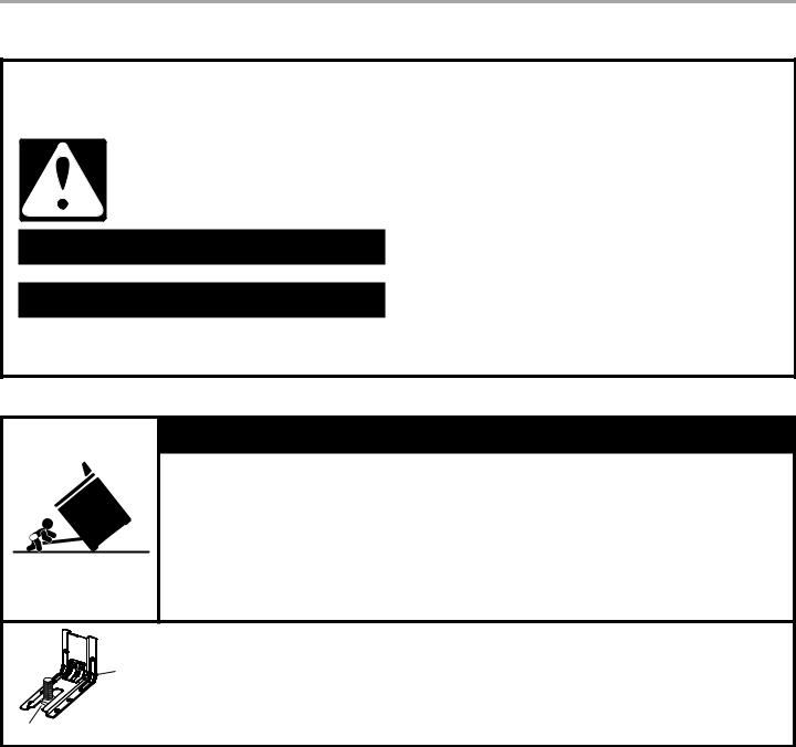
 WARNING
Tip Over Hazard
A child or adult can tip the range and be killed.
Install anti-tip bracket to floor or wall per installation instructions.
Slide range back so rear range foot is engaged in the slot of the anti-tip bracket.
Re-engage anti-tip bracket if range is moved.
Do not operate range without anti-tip bracket installed and engaged.
Failure to follow these instructions can result in death or serious burns to children and adults.
Anti-Tip
Bracket
Range Foot
To verify the anti-tip bracket is installed and engaged:
•Slide range forward.
•Look for the anti-tip bracket securely attached to floor or wall.
•Slide range back so rear range foot is under anti-tip bracket.
•See installation instructions for details.
2
INSTALLATION REQUIREMENTS
Tools and Parts
Gather the required tools and parts before starting installation. Read and follow the instructions provided with any tools listed here.
Tools needed
■Tape measure
■Flat-blade screwdriver
■Phillips screwdriver
■Level
■Hammer
■Hand or electric drill
■Wrench or pliers
■Marker or pencil
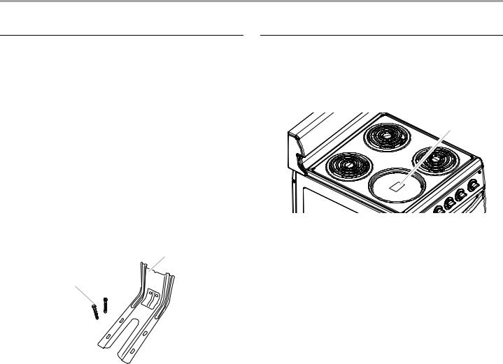
Parts supplied
Check that all parts are included.
■Masking tape
■Wire strippers
■³⁄ " nut driver
■¹⁄ " (3.2 mm) drill bit (for wood floors)
■³⁄" (4.8 mm) carbidetipped masonry drill bit (for concrete/ceramic floors)
A
B
A.Anti-tip bracket
B.#12 x 1⁄" screws (2)
■Anti-tip bracket must be securely mounted to floor or wall. Thickness of flooring may require longer screws to anchor bracket to floor.
Parts needed
If using a power supply cord:
■A UL listed power supply cord kit marked for use with ranges. The cord should be rated at 250 volts minimum, 40 amps or 50 amps that is marked for use with nominal 1³⁄ " (3.5 cm) diameter connection opening and must end in ring terminals or open-end spade terminals with upturned ends.
■A UL listed strain relief.
Check local codes. Check existing electrical supply. See the “Electrical Requirements” section.
It is recommended that all electrical connections be made by a licensed, qualified electrical installer.
Location Requirements
IMPORTANT: Observe all governing codes and ordinances.
■It is the installer's responsibility to comply with installation clearances specified on the model/serial rating plate. The model/serial rating plate is located on under the left front burner bowl.
A
A.Model/serial rating plate
■The range should be located for convenient use in the kitchen.
■Recessed installations must provide complete enclosure of the sides and rear of the range.
■To eliminate the risk of burns or fire by reaching over heated surface units, cabinet storage space located above the surface units should be avoided. If cabinet storage is to be provided, the risk can be reduced by installing a range hood that projects horizontally a minimum of 5" (12.7 cm) beyond the bottom of the cabinets.
■Cabinet opening dimensions that are shown must be used. Given dimensions are minimum clearances.
■The floor anti-tip bracket must be installed. To install the antitip bracket shipped with the range, see “Install Anti-Tip Bracket” section.
■Grounded electrical supply is required. See the “Electrical Requirements” section.
■Contact a qualified floor covering installer to check that the floor covering can withstand at least 200°F (93°C).
■Use an insulated pad or ¼" (0.64 cm) plywood under range if installing range over carpeting.
IMPORTANT: To avoid damage to your cabinets, check with your builder or cabinet supplier to make sure that the materials used will not discolor, delaminate or sustain other damage. This oven has been designed in accordance with the requirements of UL and CSA International and complies with the maximum allowable wood cabinet temperatures of 194°F (90°C).
Mobile Home - Additional Installation Requirements
The installation of this range must conform to the Manufactured Home Construction and Safety Standard, Title 24 CFR, Part 3280 (formerly the Federal Standard for Mobile Home Construction and Safety, Title 24, HUD Part 280). When such standard is not applicable, use the Standard for Manufactured Home Installations, ANSI A225.1/NFPA 501A or with local codes.
Mobile home installations require:
■When this range is installed in a mobile home, it must be secured to the floor during transit. Any method of securing the range is adequate as long as it conforms to the standards listed above.
■Four-wire power supply cord or cable must be used in a mobile home installation. The appliance wiring will need to be revised. See “Electrical Connection” section.
3

Product Dimensions |
|
Cabinet Dimensions |
|
|
|
Cabinet opening dimensions shown are for 25" (64.0 cm) |
|
|
|
countertop depth, 24" (61.0 cm) base cabinet depth and |
|
|
|
36" (91.4 cm) countertop height. |
|
|
|
If the cabinet depth is greater than 24" (61.0 cm), the oven frame |
|
|
|
must extend beyond cabinet fronts by ½" (13.0 mm) minimum. |
|
|
|
IMPORTANT: If installing a range hood or microwave hood |
|
|
|
combination above the range, follow the range hood or |
|
|
|
microwave hood combination installation instructions for |
|
|
|
dimensional clearances above the cooktop surface. |
|
|
|
B |
|
A |
|
D |
F |
|
|
C |
|
|
|
D |
|
|
|
A |
|
|
|
E |
|
B |
C |
G |
|
|
|
||
|
|
G |
|
A. 36" (91.4 cm) |
|
H |
|
B.19½" (49.5 cm)
C.24½" (62.2 cm)
D.42" (106.7 cm)
A.18" (45.7 cm) min. clearance upper side cabinet to countertop
B.13" (33.0 cm) max. upper cabinet depth
C.20" (50.8 cm) min. cabinet opening width
D.20¹⁄" (51.1 cm) opening width
E.5" (12.7 cm) min. countertop space to side wall or other combustible material
F.For minimum clearance to top of cooktop, see NOTE.
G.Wall receptacle - 8" (20.3 cm) from either cabinet,
H.5½" (14.0 cm) max. from floor. Locate 120/240-volt receptacle in shaded area.
NOTE: 24" (61.0 cm) minimum when bottom of wood or metal cabinet is covered by not less than ¼" (0.64 cm) flame retardant millboard covered with not less than No. 28 MSG sheet steel, 0.015" (0.4 mm) stainless steel, 0.024" (0.6 mm) aluminum or 0.020" (0.5 mm) copper.
30" (76.2 cm) minimum clearance between the top of the cooking platform and the bottom of an uncovered wood or metal cabinet.
4
 Loading...