

Page 1

M155
Self-Propelled Windrower
Operator ’s Manual
169883 Revision A
Original Instruction
The harvesting specialists worldwide.
Page 2
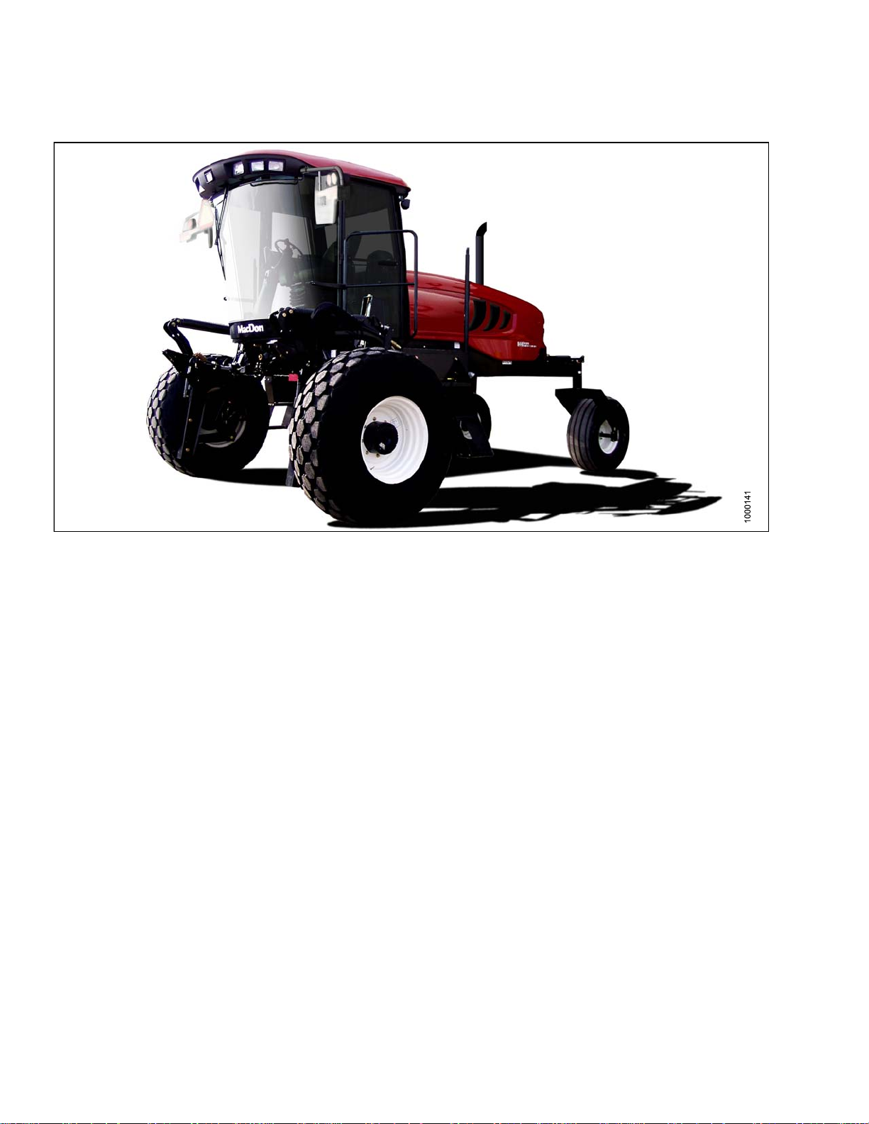
This manual contains instructions for SAFETY, OPERATION, and MAINTENANCE/SERVICE for the MacDon M155
Self-Propelled Windrower. Featuring the Dual Direction
®
and Ultra Glide®suspension on the M155.
Published June, 2014
California Proposition 65 Warning
Diesel engine exhaust and some of its constituents are known to the State of California to cause cancer, birth defects,
and other reproductive harm. Battery posts, terminals, and related accessories contain lead and lead components.
Wash hands after handling.
Page 3

Declaration of Conformity
Figure 1
ntinued on next page.
Co
169883
i
Revision A
Page 4

Whole Body and Hand-Arm Vibration Levels
The weighted root mean square acceleration to which the whole body is subjected to ranges from 0.57 to 1.06 m/s
as measured on a representative machine during typical operations and analyzed in accordance with ISO 5008.
2
During the same operations, the weighted root means square hand-arm vibration was less than 1.45 m/s
analyzed in accordance with ISO 5349. These acceleration values depend on the roughness of the ground, the
speeds at which the windrower is operated, the operator's experience, weight and driving habits.
when
Noise Levels
The A-weigh
on several r
engine spee
t sound pressure levels inside the operator's station ranged from 70.1 to 73.1 dB(A) as measured
epresentative machines in accordance with ISO 5131. The sound pressure level depends upon the
d and load, field and crop conditions and the type of platform used.
2
169883
i
i
Revision A
Page 5

Introduction
This manual contains information on the MacDon M155 Self-Propelled Windrower, which is designed to cut and lay
in windrow s a wide variety of grain, hay, and specialty crops. Windrowing allows sta rting the harvest earlier, protects
the crop from wind damage, and gives you more flexibility in scheduling combine time.
The power unit (referred to in this manual as the “windrower”), when coupled with one of the specially designed
auger, rotary, or draper headers, provides a package which incorporates many features and improvements in design.
The M155 Windrow er is Dual Direction
engine-forward modes. Right-hand and left-hand designations are therefore determined by the operator’s
position, facing the direction of travel. This manual uses the terms “right cab-forward”, “left cab-forward”, “right
engine-forward”, and “left engine-forward” when referencing specific locations on the machine.
Use this m anual as your first source of information about the machine. Use the Table of Contents and the Index to
guide you to specific areas. Stud y the Table of C on te nts to fa miliarize yourself with h o w the material is organized.
If you follow the instructions given here, your M155 Windrower will work well for many years.
Use this manual in conjunction with your header operator's manual.
A manual storage case is provided in the cab. Keep this manual handy for frequent reference and to pass on to new
Operators or Owners. Call your Dealer if you need assistance, information, or additional copies of this manual.
CAREFULLY READ ALL THE MATERIAL PROVIDED BEFORE ATTEMPTING TO USE THE MACHINE.
NOTE: Keep your MacDon publications up-to-date. The most current version can be downloaded from our website
www.macdon.com or from our Dealer-only site (https://portal.macdon.com) (login required).
®
, meaning that the windrower can be driven in the cab-forward or the
169883
ii
i
Revision A
Page 6

List of Revisions
At MacDon, we’
documentatio
Summary of Change
Added new safety sign locations. 1.11 Safety Sign Locations, page 13
Updated lif
Restructured the header attach and detach procedures
to improve readability.
Removed r
in the Lub
with new d
Updated a
unit.
Added im
Replaced the missing Hydraulic Oil
Maintenance instruction.
Added the Adjusting Reel Drop Rate section. Adjusting Reel Drop Rate, page 367
Added image and instruction for 10–bolt wheel
tightening procedure and torque specifications
re continuously making improvements: occasionally these improvements impact product
n. The following list provides an account of major changes from the previous version of this document.
Location
t linkage images to include the new decal.
eference to the walking beam grease zerk
rication Points section. No longer required
esign.
ir conditioning unit images to show the new
age showing new battery boost post location.
Various locations throughout4.4.3 Levelling the Header,
page 143
4.5 Attaching and Detaching Headers, page 157
5.6.2 Lubrication Points, page 274
Air Conditioning Evaporator, page 288
Boostin
Checking and Filling Hydraulic Oil, page 360
Various locations throughout Tightening Drive Wheel
Nuts, page 371
g the Battery, page 331
Updated the replacing cabin dome light procedure. Dome Light, page 353
d case drain kit information to the Options and
Adde
chments section.
Atta
Added mechanical center-link to the Option and
Attachments section.
5 Case Drain Kit, page 405
7.1.
7.1.15 Mechanical Center-Link, page 407
169883
v
i
Revision A
Page 7
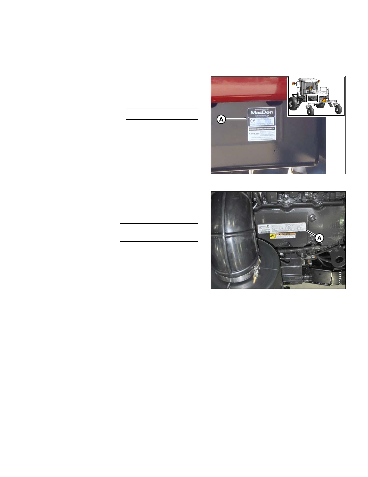
Serial Number
Record the mod
The serial num
main frame nea
WINDROWER MO
NUMBER
YEAR OF MANUFACTURE
The serial number plate (A) is located on top of the engine
cylinder head cover.
ENGINE SERIAL
NUMBER
DATE OF
MANUFACTURE
el number, model year, and serial number of the windrower and engine on the lines below.
ber plate (A) is located on the left side of the
r the walking beam.
DEL
Figure 2: Machine Serial Number Location
169883
Figure 3: Engine Serial Number Location
v
Revision A
Page 8

Page 9

TABLE OF CONTENTS
Declaration of Conformity.................................................................................................................. i
Whole Body and Hand-Arm Vibration Levels ......................................................................................ii
Noise Levels .................................................................................................................................... ii
Introduction ..................................................................................................................................... iii
List of Revisions ..............................................................................................................................iv
Serial Number ................................................................................................................................. v
1 Safety.................................................................................................................................................... 1
1.1 Safety Alert Symbols........................................................................................................................ 1
1.2 Signal Words................................................................................................................................... 2
1.3 General Safety ................................................................................................................................ 3
1.4 Maintenance Safety ......................................................................................................................... 5
1.5 Hydraulic Safety .............................................................................................................................. 6
1.6 Tire Safety....................................................................................................................................... 7
1.7 Battery Safety.................................................................................................................................. 8
1.8 Welding Precaution.......................................................................................................................... 9
1.9 Engine Safety ................................................................................................................................ 10
1.9.1 High Pressure Rails................................................................................................................ 10
1.9.2 Engine Electronics ..................................................................................................................11
1.10 Safety Signs.................................................................................................................................. 12
1.10.1 Installing Safety Decals .......................................................................................................... 12
1.11 Safety Sign Locations .................................................................................................................... 13
1.12 Interpreting Safety Signs ................................................................................................................ 17
2 Description.......................................................................................................................................... 27
2.1 D efinitions ..................................................................................................................................... 27
2.2 Specifications................................................................................................................................ 29
2.3 Windrower Dimensions .................................................................................................................. 32
2.4 Component Location...................................................................................................................... 34
3 Operator’s Station ............................................................................................................................... 37
3.1 Operator Console .......................................................................................................................... 37
3.2 Operator Presence System ............................................................................................................ 39
3.2.1 Header Drive ......................................................................................................................... 39
3.2.2 Engine and Transmission........................................................................................................ 39
3.3 Operator’s Seat Adjustments .......................................................................................................... 40
3.3.1 Fore-Aft ................................................................................................................................. 40
3.3.2 Seat Suspension and Height ................................................................................................... 40
3.3.3 Vertical Dampener.................................................................................................................. 41
3.3.4 Armrest ................................................................................................................................. 41
3.3.5 Fore-Aft Isolator Lock ............................................................................................................. 42
3.3.6 Seat Tilt................................................................................................................................. 42
3.3.7 Armrest Angle........................................................................................................................ 43
3.3.8 Lumbar Support ..................................................................................................................... 43
3.4 Training Seat................................................................................................................................. 44
3.5 Seat Belts ..................................................................................................................................... 45
3.6 Steering Column Adjustment .......................................................................................................... 46
3.7 Lighting ......................................................................................................................................... 47
3.7.1 Cab-Forward Lighting: Field.................................................................................................... 47
3.7.2 Engine-Forward Lighting: Road............................................................................................... 49
3.7.3 Cab-Forward Lighting: Road (Optional) ................................................................................... 50
3.7.4 Beacon Lighting: Export (N.A. Optional) .................................................................................. 51
3.7.5 Optional HID Auxiliary Lighting (if installed ) .............................................................................. 51
3.8 Windshield Wipers......................................................................................................................... 53
3.9 Rear View Mirrors .............................................................................................................
3.10 Cab Temperature........................................................................................................................... 55
............. 54
169883
ii
v
Revision A
Page 10

TABLE OF CONTENTS
3.10.1 Heater Shut-Off...................................................................................................................... 55
3.10.2 Air Distribution ....................................................................................................................... 55
3.10.3 Controls................................................................................................................................. 56
3.11 Interior Lights ................................................................................................................................ 57
3.12 Operator Amenities ........................................................................................................................ 58
3.13 Radio ............................................................................................................................................ 60
3.13.1 AM/FM Radio......................................................................................................................... 60
3.13.2 Antenna Mounting .................................................................................................................. 60
3.14 Horn ............................................................................................................................................. 62
3.15 Engine Controls and Gauges.......................................................................................................... 63
3.16 Windrower Controls ....................................................................................................................... 64
3.17 Header Controls ............................................................................................................................ 66
3.17.1 Header Drive Switch............................................................................................................... 66
3.17.2 Header Drive Reverse Button..................................................................................................66
3.17.3 Ground Speed Lever (GSL) Header Switches .......................................................................... 67
Display Selector Switch................................................................................................... 68
Reel Position Switches.................................................................................................... 68
Header Position Switches................................................................................................ 69
Reel and Disc Speed Switches ........................................................................................ 69
3.17.4 Console Header Switches....................................................................................................... 70
Deck Shift/Float Preset Switch......................................................................................... 70
Double Windrow Attachment (DWA) / Swath Roller Switch (if installed) .............................. 71
3.18 Cab Display Module (CDM) ............................................................................................................ 72
3.18.1 Engine and Windrower Functions ............................................................................................ 72
3.18.2 Header Functions................................................................................................................... 73
3.18.3 Operating Screens ................................................................................................................. 74
Ignition ON, Engine Not Running ..................................................................................... 74
Engine-Forward, Engine Running .................................................................................... 75
Cab-Forward, Engine Running, Header Disengaged ......................................................... 75
Cab-Forward, Engine Running, Header Engaged, Auger Header Index Switch OFF............ 76
Cab-Forward, Engine Running, Header Engaged, Auger Header Index Switch ON ............. 77
Cab-Forward, Engine Running, Header Engaged, Draper Header, Index Switch OFF........... 78
Cab-Forward, Engine Running, Header Engaged, Draper Header, Index Switch ON ........... 79
Cab-Forward, Engine Running, Header Engaged, Rotary Header Installed......................... 80
Miscellaneous Operational Information............................................................................. 81
3.18.4 Cab Display Module (CDM) Warning/Alarms ............................................................................ 82
Engine Warning Lights .................................................................................................... 82
Display Warnings and Alarms .......................................................................................... 83
3.18.5 Cab Display Module (CDM) Programming................................................................................ 86
Programming Guidelines................................................................................................. 87
Detailed Programming Menu Flow Chart .......................................................................... 88
Operating Information Screens ........................................................................................ 94
3.18.6 Engine Error Codes................................................................................................................ 97
3.18.7 Cab Display Module (CDM) and Windrower Control Module (WCM) Fault Codes ....................... 97
4 Operation ............................................................................................................................................ 99
4.1 Owne r/Ope rato r Responsibilities..................................................................................................... 99
4.2 S ymbol Definitions........................................................................................................................100
4.2.1 Engine Functions ..................................................................................................................100
4.2.2 Windrower Operating Symbols ............................................................................................... 101
4.2.3 Header Functions..................................................................................................................102
4.3 Operating the Windrower...............................................................................................................103
4.3.1 Operational Safety ................................................................................................................103
4.3.2 Break-In Period.....................................................................................................................104
4.3.3 Preseason Checks/Annual Service.........................................................................................104
169883
iii
v
Revision A
Page 11

TABLE OF CONTENTS
A/C Compressor Coolant Cycling....................................................................................105
4.3.4 Daily Check ..........................................................................................................................105
4.3.5 Engine Operation ..................................................................................................................106
Starting the Engine ........................................................................................................106
Engine Warm-Up ...........................................................................................................108
Engine Intermediate Speed Control (ISC)........................................................................ 108
Shutting Down the Engine ..............................................................................................109
Fuelling .........................................................................................................................109
Engine Temperature.......................................................................................................110
Engine Oil Pressure ....................................................................................................... 110
Electrical ....................................................................................................................... 111
Engine Warning Lights ................................................................................................... 111
4.3.6 Windrower Operation............................................................................................................. 111
Ingress/Egress ..............................................................................................................113
Driving Forward in Cab-Forward Mode ............................................................................ 114
Driving in Reverse in Cab-Forward Mode ........................................................................115
Driving Forward in Engine-Forward Mode........................................................................116
Driving in Reverse in Engine-Forward Mode .................................................................... 117
Spin Turning .................................................................................................................. 118
Stopping .......................................................................................................................118
4.3.7 Adjusting Caster Tread Width................................................................................................. 11 9
4.3.8 Transporting the Windrower ................................................................................................... 121
Driving on the Road .......................................................................................................121
Towing Header with Windrower.......................................................................................124
Towing the Windrower (Emergency)................................................................................ 134
Final Drives...................................................................................................................135
4.3.9 Storing the Windrower ...........................................................................................................135
4.4 Operating with a Header ...............................................................................................................137
4.4.1 Header Safety Props.............................................................................................................137
4.4.2 Header Float.........................................................................................................................139
Float Operating Guidelines ............................................................................................. 139
Checking Float ..............................................................................................................139
Float Options.................................................................................................................142
4.4.3 Levelling the Header..............................................................................................................143
4.4.4 Header Drive ........................................................................................................................145
Engaging and Disengaging the Header ...........................................................................145
Reversing the Header .................................................................................................... 147
4.4.5 Adjusting Header Angle.........................................................................................................147
Checking Self-Locking Center-Link Hook.........................................................................148
4.4.6 Cutting Height.......................................................................................................................150
Return to Cut ................................................................................................................150
Programming Return to Cut Feature ............................................................................... 151
Using Return to Cut Feature........................................................................................... 152
Auto Raise Height.......................................................................................................... 153
Programming Auto Raise Height Feature ........................................................................153
Using Auto Raise Height Feature....................................................................................154
Header Drop Rate..........................................................................................................154
4.4.7 Double Windrowing ...............................................................................................................154
Double Windrow Attachment (DWA) Deck Position ..........................................................155
Double Windrow Attachment (DWA) Draper Speed .......................................................... 155
4.4.8 Swath Roller Operation..........................................................................................................156
4.5 Attaching and Detaching Headers..................................................................................................157
4.5.1 Attaching a D-Series Header..................................................................................................157
Attaching a D-Series Header: Hydraulic Center-Link with Optional Self-Alignment .............157
169883
x
i
Revision A
Page 12

TABLE OF CONTENTS
Attaching a D-Series Header: Hydraulic Center-Link without Self-Alignment......................162
Attaching a D-Series Header: Mechanical Center-Link ..................................................... 168
4.5.2 Detaching a D-Series Header ................................................................................................172
Detaching a D-Series Header: Hydraulic Center-Link ....................................................... 173
Detaching a D-Series Header: Mechanical Center-Link .................................................... 176
4.5.3 Attaching an A-Series Header ................................................................................................ 180
Attaching an A-Series Header: Hydraulic Center-Link with Optional Self-Alignment............180
Attaching an A-Series Header: Hydraulic Center-Link without Self-Alignment ....................185
Attaching an A-Series Header: Mechanical Center-Link ...................................................191
4.5.4 Detaching an A-Series Header............................................................................................... 196
Detaching an A-Series Header: Hydraulic Center-Link .....................................................197
Detaching an A-Series Header: Mechanical Center-Link ..................................................200
4.5.5 Attaching an R-Series Header................................................................................................204
Attaching an R-Series Header: Hydraulic Center-Link with Optional Self-Alignment ...........204
Attaching an R-Series Header: Hydraulic Center-Link without Self-Alignment ....................210
Attaching an R-Series Header: Mechanical Center-Link ................................................... 215
4.5.6 Detaching an R-Series Header...............................................................................................220
Detaching an R-Series Header: Hydraulic Center-Link.....................................................220
Detaching an R-Series Header: Mechanical Center-Link..................................................223
4.6 Operating with a D-Series Header..................................................................................................227
4.6.1 Configuring Hydraulics...........................................................................................................227
4.6.2 Attaching Header Boots.........................................................................................................228
4.6.3 Header Position ....................................................................................................................228
4.6.4 Reel Fore-Aft Position ...........................................................................................................229
4.6.5 Reel Height...........................................................................................................................229
4.6.6 Reel Speed...........................................................................................................................229
Reel to Ground Speed ...................................................................................................229
Reel Only Speed ...........................................................................................................231
4.6.7 Draper Speed .......................................................................................................................232
Draper to Ground Speed................................................................................................232
Setting Draper Minimum Speed......................................................................................233
Setting Draper Index ...................................................................................................... 234
Setting Draper Speed Independent of Ground Speed.......................................................235
4.6.8 Knife Speed..........................................................................................................................236
Setting Knife Speed “On the Go”.....................................................................................237
4.6.9 Deck Shift (Optional) .............................................................................................................238
Deck Shift .....................................................................................................................238
Setting Float Options with Deck Shift...............................................................................238
4.7 Operating with an A-Series Header................................................................................................240
4.7.1 Auger Speed.........................................................................................................................240
Auger Speed on A30-D Headers.....................................................................................240
Auger Speed on A40-D Headers.....................................................................................240
4.7.2 Reel Speed...........................................................................................................................241
Reel Speed on A30-D Headers.......................................................................................241
Reel Speed on A40-D Headers.......................................................................................241
4.7.3 Knife Speed..........................................................................................................................245
Setting Knife Speed “On the Go”.....................................................................................246
4.8 Operating with an R-Series Header................................................................................................247
4.9 Disc Speed...................................................................................................................................248
4.9.1 Setting Disc Speed................................................................................................................248
5 Maintenance and Servicing................................................................................................................249
5.1 Preparation For Servicing..............................................................................................................249
5.2 Torque Specifications .................................................................................................................... 250
5.2.1 SAE Bolt Torque Specifications ..............................................................................................250
169883
x
Revision A
Page 13

TABLE OF CONTENTS
5.2.2 Metric Bolt Specifications.......................................................................................................252
5.2.3 Metric Bolt Specifications Bolting into Cast Aluminum .............................................................. 255
5.2.4 Flare-Type Hydraulic Fittings..................................................................................................255
5.2.5 O-Ring Boss (ORB) Hydraulic Fittings (Adjustable)..................................................................257
5.2.6 O-Ring Boss (ORB) Hydraulic Fittings (Non-Adjustable) .......................................................... 259
5.2.7 O-Ring Face Seal (ORFS) Hydraulic Fittings...........................................................................260
5.3 Maintenance Specifications ........................................................................................................... 262
5.3.1 Recommended Fuel, Fluids, and Lubricants............................................................................262
Storing Lubricants and Fluids .........................................................................................262
Fuel Specifications.........................................................................................................262
Lubricants, Fluids, and System Capacities.......................................................................263
Filter Part Numbers........................................................................................................ 264
5.3.2 Conversion Chart ..................................................................................................................264
5.4 Engine Compartment Hood ...........................................................................................................266
5.4.1 Opening Hood (Lower Position)..............................................................................................266
5.4.2 Closing Hood (Lower Position) ............................................................................................... 267
5.4.3 Opening Hood (Highest Position) ...........................................................................................267
5.4.4 Closing Hood (Highest Position).............................................................................................268
5.5 Maintenance Platforms .................................................................................................................269
5.5.1 Opening Platforms (Standard Position) ................................................................................... 269
5.5.2 Closing Platforms (Standard Position).....................................................................................270
5.5.3 Opening Platforms (Major Service Position) ............................................................................270
5.5.4 Closing Platforms (Major Service Position)..............................................................................272
5.6 Windrower Lubrication ..................................................................................................................273
5.6.1 Lubricating the Windrower .....................................................................................................273
5.6.2 Lubrication Points..................................................................................................................274
5.7 Operator’s Station.........................................................................................................................275
5.7.1 Seat Belts.............................................................................................................................275
5.7.2 Safety Systems.....................................................................................................................275
Checking Operator Presence System..............................................................................275
Checking Engine Interlock..............................................................................................276
5.7.3 Ground Speed Lever (GSL) Adjustments................................................................................276
Adjusting Ground Speed Lever (GSL) Lateral Movement..................................................276
Adjusting Ground Speed Lever (GSL) Fore-Aft Movement................................................277
5.7.4 Steering Adjustments ............................................................................................................278
Checking Steering Link Pivots ........................................................................................ 278
Checking Steering Chain Tension ...................................................................................280
5.7.5 Park Brake............................................................................................................................281
Adjusting and Replacing Interlock Switch ........................................................................281
5.7.6 Heating, Ventilating, and Air Conditioning (HVAC) System .......................................................284
Fresh Air Intake Filter.....................................................................................................284
Return Air Cleaner/Filter.................................................................................................286
Air Conditioning Condenser............................................................................................288
Air Conditioning Evaporator ............................................................................................288
Air Conditioning Compressor .......................................................................................... 290
5.7.7 Engine..................................................................................................................................291
General Engine Inspection .............................................................................................291
Turning Engine Manually................................................................................................ 292
Engine Oil .....................................................................................................................293
Air Intake System...........................................................................................................296
Fuel System ..................................................................................................................303
Engine Cooling System..................................................................................................310
Gearbox........................................................................................................................321
Exhaust System.............................................................................................................322
169883
i
x
Revision A
Page 14

TABLE OF CONTENTS
Belts .............................................................................................................................323
Engine Speed................................................................................................................326
5.7.8 Electrical System...................................................................................................................326
Battery..........................................................................................................................326
Headlights: Engine-Forward ...........................................................................................335
Field Lights: Cab-Forward ..............................................................................................339
Flood Lights: Forward .................................................................................................... 340
HID Auxiliary Lighting (Optional - MD #B5596).................................................................342
Flood Lights: Rear .........................................................................................................345
Red and Amber Lights ...................................................................................................347
Red Tail Lights (if installed)............................................................................................. 347
Beacons (if installed)......................................................................................................348
Console Gauge Light .....................................................................................................352
Dome Light....................................................................................................................353
Ambient Light ................................................................................................................353
Turn Signal Indicators ....................................................................................................354
Circuit Breakers and Fuses ............................................................................................354
5.7.9 Hydraulic System ..................................................................................................................359
Checking and Filling Hydraulic Oil ...................................................................................360
Hydraulic Oil Cooler ....................................................................................................... 361
Draining Hydraulic Oil ....................................................................................................362
Changing Hydraulic Oil Filters.........................................................................................362
Header and Reel Hydraulics...........................................................................................365
Traction Drive Hydraulics................................................................................................368
Hoses and Lines............................................................................................................369
5.7.10 Wheels and Tires ..................................................................................................................370
Drive Wheel ..................................................................................................................370
Caster Wheel ................................................................................................................376
5.7.11 Maintenance Schedule ..........................................................................................................382
Break-In Inspections ......................................................................................................383
Maintenance Schedule/Record.......................................................................................384
6 Troubleshooting.................................................................................................................................387
6.1 Engine Troubleshooting ................................................................................................................387
6.2 Electrical Troubleshooting .............................................................................................................393
6.3 Hydraulics Troubleshooting ...........................................................................................................394
6.4 Header Drive Troubleshooting .......................................................................................................395
6.5 Traction Drive Troubleshooting ......................................................................................................396
6.6 Steering and Ground Speed Control Troubleshooting......................................................................399
6.7 Cab Air Troubleshooting................................................................................................................400
6.8 Operator’s Station Troubleshooting................................................................................................404
7Opti
ons and Attachments ..................................................................................................................405
7.1 O pti
7.1.
7.1.
7.1
7.1
7.1
7.1
7.1
1.8
7.
1.9
7.
1.10
7.
1.11
7.
ons and Attachments ..............................................................................................................405
1
2
.3
.4
.5
.6
.7
M Radio........................................................................................................................405
AM/F
mated Steering Systems................................................................................................. 405
Auto
ster Spring Kit (External) ..................................................................................................405
Boo
ster Spring Kit (Internal)...................................................................................................405
Boo
e Drain Kit.......................................................................................................................405
Cas
ble Windrow Attachment (DWA) ....................................................................................... 406
Dou
per Header Reel Drive and Lift Plumbing ........................................................................... 406
Dra
gine Block Heater..............................................................................................................406
En
gine Fan Air Baffle ............................................................................................................. 406
En
ader Drive Reverser .......................................................................................................... 406
He
D Auxiliary Lighting ............................................................................................................406
HI
169883
ii
x
Revision A
Page 15

TABLE OF CONTENTS
7.1.12 Hydraulic Center-Link ............................................................................................................407
7.1.13 Light Header Flotation ...........................................................................................................407
7.1.14 Lighting and Marking for Cab-Forward Road Travel.................................................................407
7.1.15 Mechanical Center-Link.........................................................................................................407
7.1.16 Pre-Cleaner and Radiator/Charge Air Cooler Sweeps..............................................................407
7.1.17 Pressure Sensor ...................................................................................................................407
7.1.18 Rotary Header Drive Hydraulics (13-foot)................................................................................407
7.1.19 Self-Aligning Center-Link .......................................................................................................408
7.1.20 Swath Roller .........................................................................................................................408
7.1.21 Towing Harness ....................................................................................................................408
7.1.22 Warning Beacons..................................................................................................................408
7.1.23 Weight Box ...........................................................................................................................409
7.1.24 Windshield Shades................................................................................................................409
8 Engine Error Codes............................................................................................................................411
9CabDispla
Index ..................................................................................................................................................433
y Module (CDM) Error Codes ............................................................................................429
169883
iii
x
Revision A
Page 16

Page 17

1Safety
1.1 Safety Alert Symbols
This safety alert symbol indicates important safety
messages in this manual and on safety signs on
the windrower.
This symbol means:
• ATTENTION!
• BECOME ALERT!
• YOUR SAFETY IS INVOLVED!
Carefully read and follow the safety message
accompanying this symbol.
Why is safety important to you?
• Accidents disable and kill.
• Accidents cost.
• Accidentscanbeavoided.
Figure 1.
1: Safety Symbol
169883
1
Revision A
Page 18

SAFETY
1.2 Signal Words
Three signal words, DANGER, WARNING, a nd CAUTION, are used to alert you to hazardous situations. The
appropriate signal word for each situation has been selected using the following guidelines:
DANGER
Indicates an imminently hazardous situation that, if not avoided, will result in death, or serious injury.
WARNING
Indicates a pote
mayalsobeused
ntially hazardous situation that, if not avoided, could result in death, or serious injury. It
to alert against unsafe practices.
CAUTION
Indicates a potentially hazardous situation that, if not avoided, may result in minor, or moderate injury. It
may be used to alert against unsafe practices.
169883
2
Revision A
Page 19
SAFETY
1.3 General Safety
CAUTION
The following are general farm safety precautions
that should be part of your operating procedure for
all types of machinery.
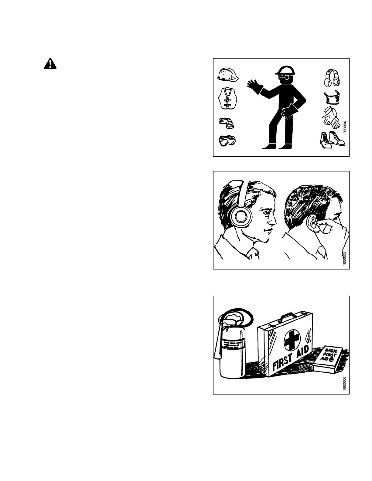
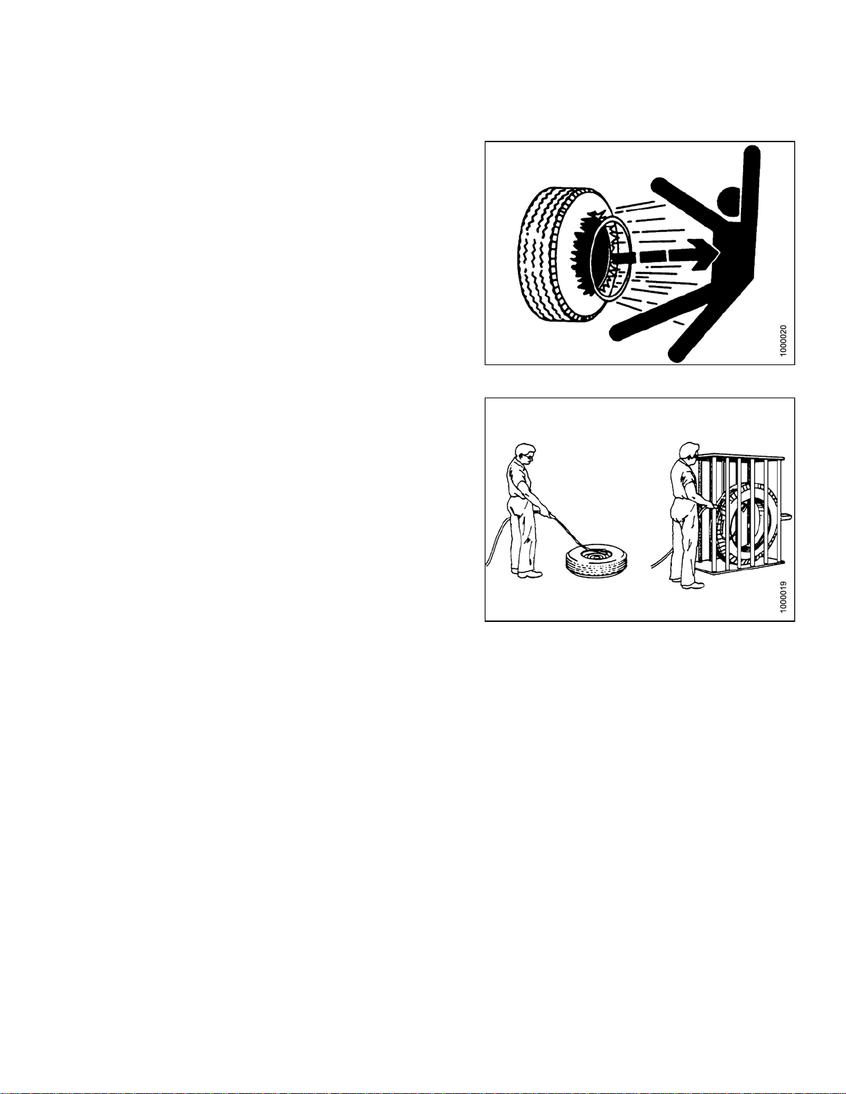
Protect yourself
• When assembling, operating, and servicing machinery,
wear all the protective clothing and personal safety
devices that COULD be necessary for the job at hand.
Don’t take chances.
• You may need:
– A hard hat
– Protective footwear with slip res ista nt soles
– Protective glasses or goggles
– Heavy gloves
– Wet weather gear
– A respirator or filter mask
– Hearing protection
Be aware that exposure to loud noise can cause
impairment or loss of hearing. Wearing suitable
hearing protection devices such as ear muffs or ear
plugs. These w ill help protect against objectionable
or loud noises.
•Provideafirs
• Keep a fire ext
fire extingui
its proper u s
• Keep young c
all times.
t aid kit for use in case of emergencies.
inguisher on the machine. Be sure the
sher is properly maintained. Be familiar with
e.
hildren away from the machinery at
Figure 1.2
Figure 1.3: Safety Equipment
: Safety Equipment
•Beawaretha
Operator is
time to cons
signs of fa
169883 3 Revision A
t accidents often happen when the
tiredorinahurrytogetfinished. Take the
ider the safest way. Never ignore warning
tigue.
Figure 1.4: Safety Equipment
Page 20
SAFETY
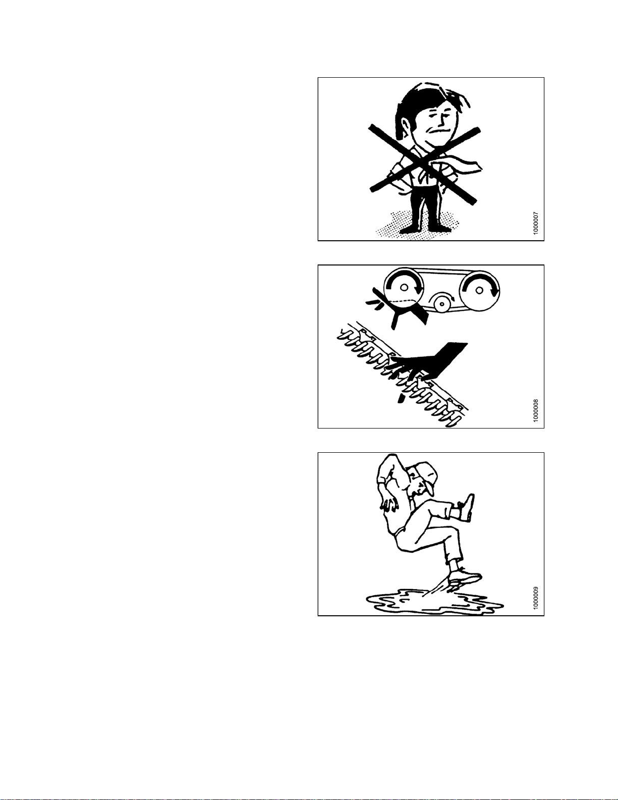
•Wearclosefitting clothing and cove r lo ng hair. Never
wear dangling items such as scarves or bracelets.
• Keep all shields in place. Never alter or remove safety
equipment. Make sure driveline guards can rotate
independently of the shaft and can telescope freely.
• Use only service and repair parts, made, or approved by
the equipment manufacturer. Substituted parts may not
meet strength, design, or safety requirements.
• Keep hands, feet, clothing, and hair away from moving
parts. Never at te mpt to clear obstructions or ob jects,
from a machine while the engine is running.
•DoNOT modify the machine. Non-authorized
modifications may impair machine function and/or
safety. It may also shorten the machine’s life.
Figure 1.5: Safety around Equipment
• Stop the engine and remove the key from ignition before
leaving operator’s seat for any reason. A child or even
a pet could engage an idling machine.
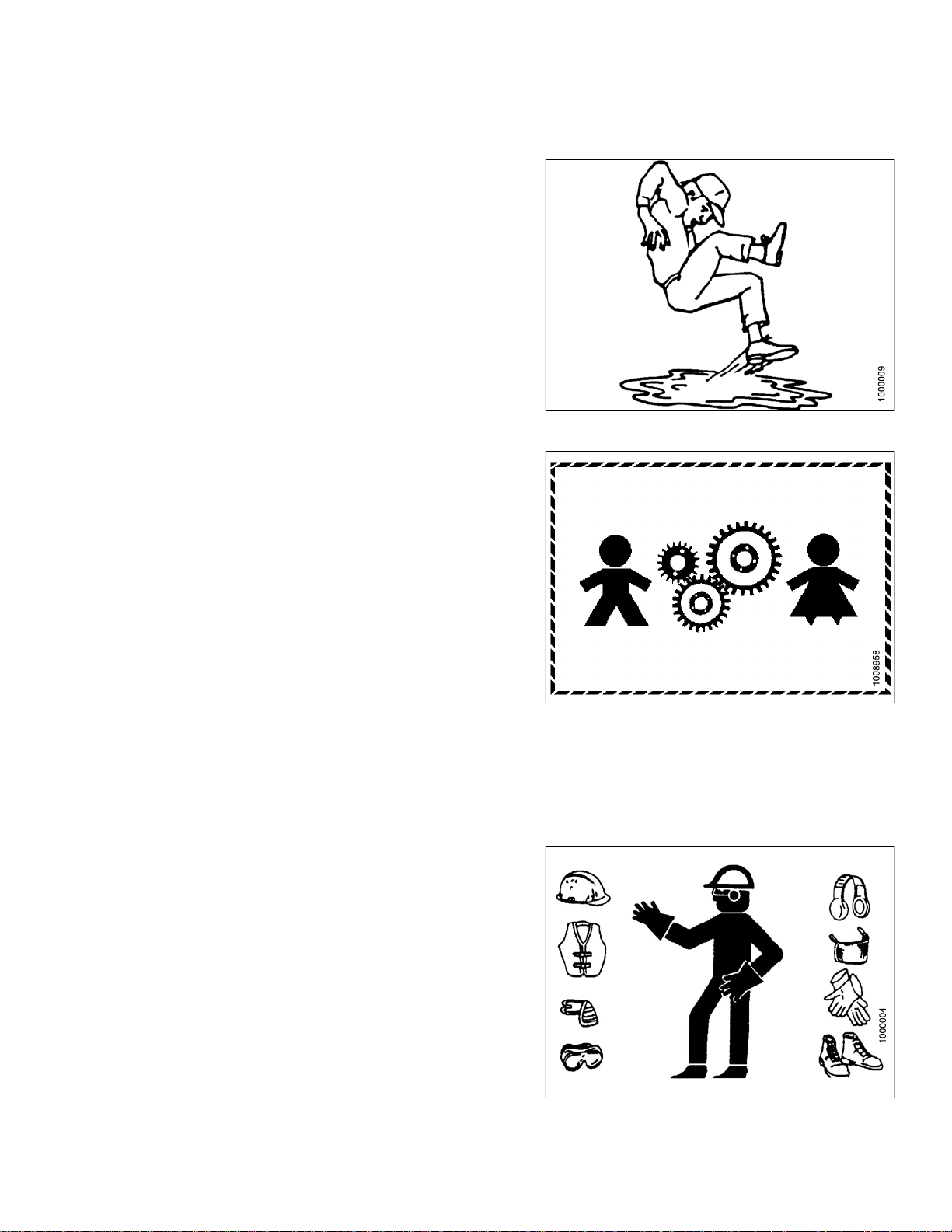
• Keep the area used for servicing machinery clean
and dry. Wet or oily floors are slippery. Wet spots
can be dangerous when working with electrical
equipment. Be sure all electrical outlets and tools are
properly grounded.
• Keep work area well lit.
• Keep machinery clean. Straw and chaff, on a hot
engine, are a fire hazard. Do NOT allow oil or grease to
accumulate on service pla tforms, ladde rs, or controls.
Clean machines before storage.
• Never use gasoline, naphtha, or any volatile material
for cleaning purposes. These materials may be toxic
and/or flammable.
• When storing machinery, cover sharp or extending
components to prevent injury from accidental contact.
Figure 1.6: Safety around Equipment
Figure 1.7: Safety around Equipment
169883
4
Revision A
Page 21
SAFETY
1.4 Maintenance Safety
To ensure your safety while maintaining the machine:
• Review the operator’s manual and all safety items
before operation and/or maintenance of the machine.
• Place all controls in Neutral, stop the engine, set the
park brake, remove the ignition key, and wait for all
moving parts to stop before servicing, adjusting, and/or
repairing.
• Follow good shop practices:
– Keep service area clean and dry.
– Be sure electrical outlets and tools are
properly grounded.
– Use adequate light for the job at hand.
• Relieve pressure from hydraulic circuits before servicing
and/or disconnecting the machine.
• Before applying pressure to a hydraulic system, make
sure all components are tight and that steel lines, hoses,
and couplings are in good condition.
Figure 1.8: Safety around Equipment
• Keep hands, feet, clothing, and hair away from all
moving and/or rotating parts.
• Clear the area of bystand ers especially children when
carrying out any maintenance and repairs or when
making any adjustments.
• Install transport lock or place safety stands under the
frame before working under the windrower.
• If more than one person is servicing the machine at the
same time, be aware that rotating a driveline or other
mechanically driven component by hand (for example,
accessing a lube fitting) will cause drive components in
other areas (belts, pulleys, and knife) to move. Stay
clear of driven components at all times.
• Wear protective gea
• Wear heavy gloves w
r when working on the machine.
hen working on knife components.
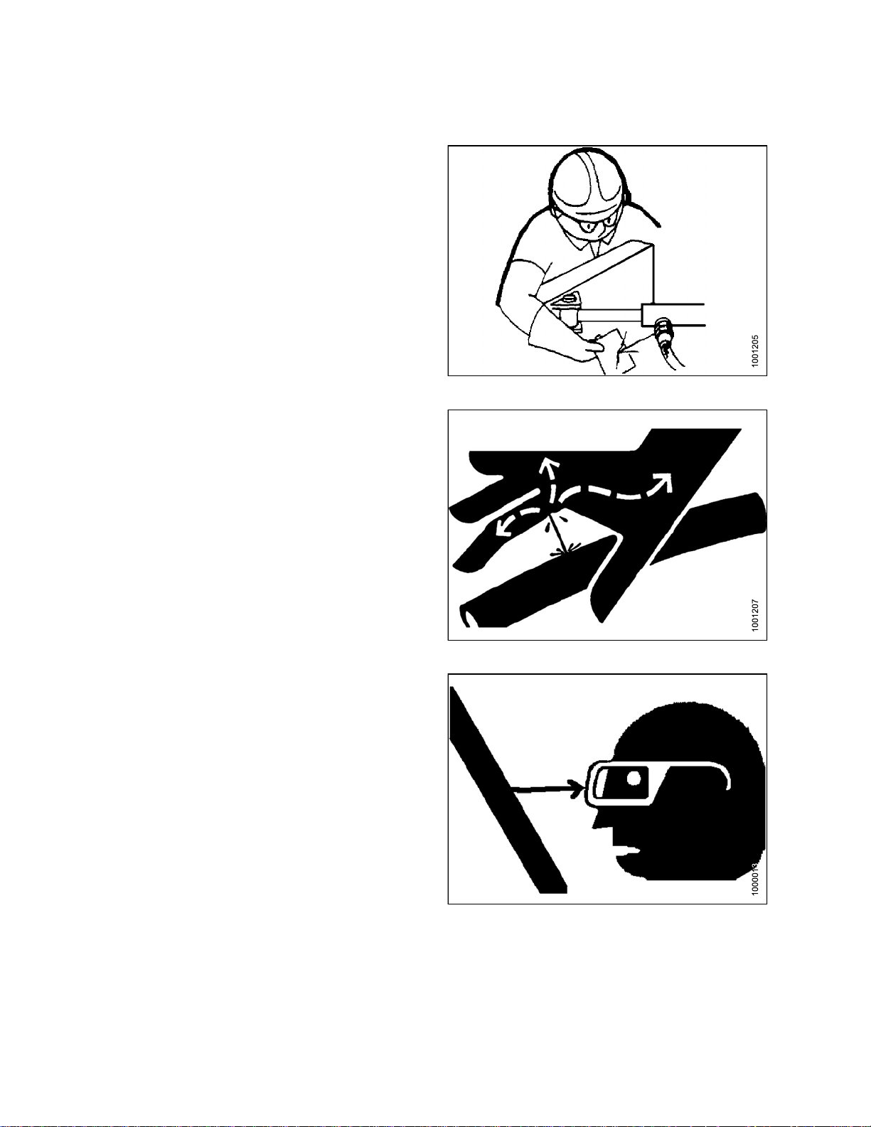
Figure 1.9: Eq
uipment NOT Safe for Children
Figure 1.10: Saf
169883 5 Revision A
ety Equipment
Page 22
SAFETY
1.5 Hydraulic Safety
• Always place all hydraulic controls in Neutral
before dismounting.
• Make sure that all components in the hydraulic system
are kept in good condition and clean.
• Replace any worn, cut, abraded, flattened, or crimped
hoses and steel lines.
•DoNOT attempt any makeshift repairs to the hydraulic
lines, fittings, or hoses by using tapes, clamps, cements,
or welding. The hydraulic system operates under
extremely hig h pressure. Such makeshift repairs will fail
suddenly and create a hazardous and unsafe condition.
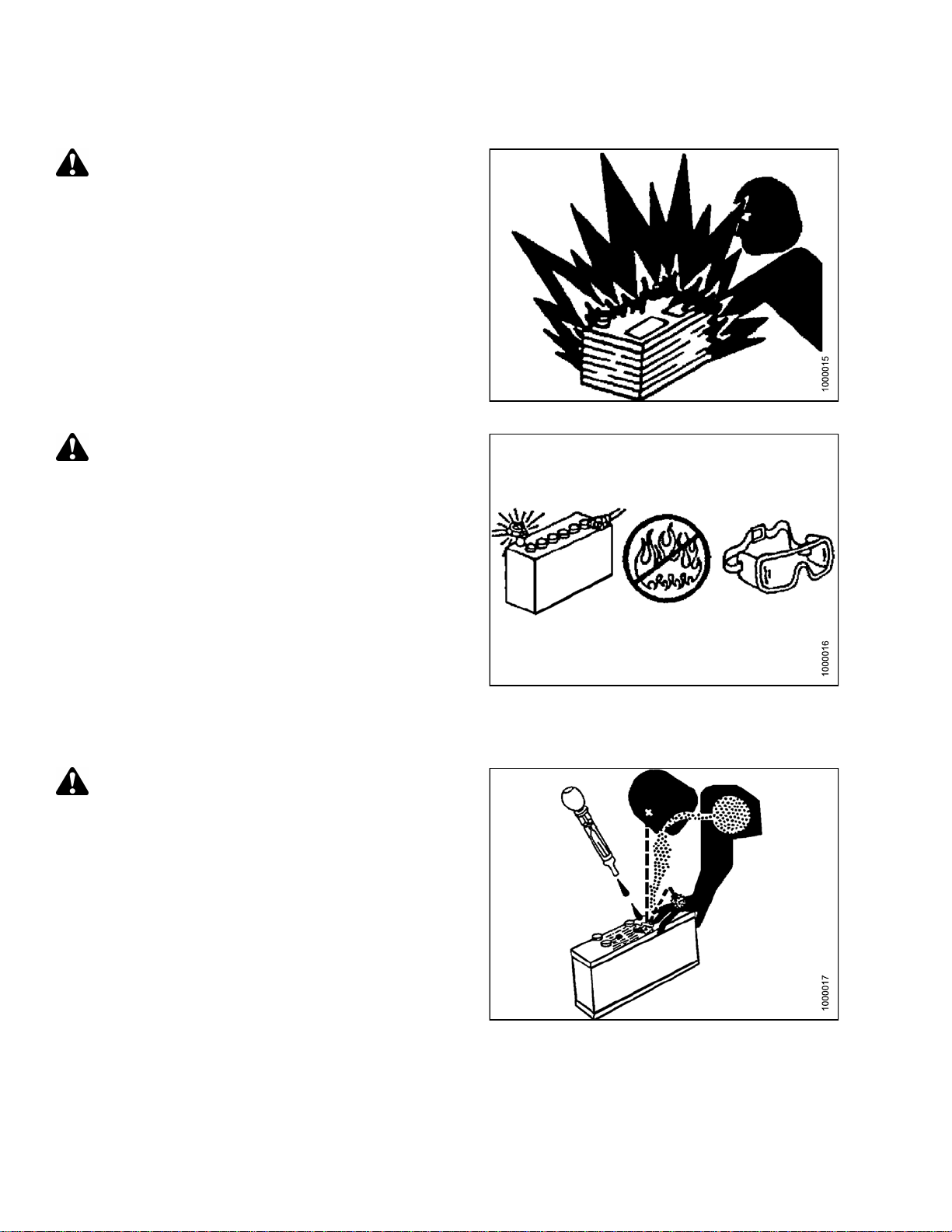
Figure 1.11: Checking Hydraulic Leaks
•Wearprope
for a highcardboar
and ident
•Ifinjure
hydrauli
Serious
hydraul
• Before applying pressure to a hydraulic system, make
sure all components are tight and that steel lines, hoses,
and couplings are in good condition.
r hand and eye protection when searching
pressure hydraulic leak. U se a piece of
d as a backstop instead of hands to isolate
ify a leak.
d by a concentrated high-pressure stream of
c fluid, seek medical attention immediately.
infection or toxic reaction can develop from
ic fluid piercing the skin.
Figure
1.12: Hydraulic Pressure Hazard
ure 1.13: Safety Glasses
Fig
169883 6 Revision A
Page 23
SAFETY
1.6 Tire Safety
• Failure to follow proper procedures when mounting a tire
on a wheel or rim can produce an explosion that may
result in serious injury or death.
•DoNOT attempt to mount a tire unless you have the
proper training and equipment.
• Haveaqualified tire dealer or repair service perform
required tire maintenance.
Figure 1.14: Over-Inflated Tire
Figure 1.15: Safely Filling a Tire with Air
169883
7
Revision A
Page 24
SAFETY
1.7 Battery Safety
WARNING
• Keep all sparks and flames away from the
batteries, as a gas given off by electrolyte
is explosive.
• Ventilate when charging in enclosed space.
WARNING
• Wear safety glasses when working near batteries.
• Do NOT tip batteries more than 45° to avoid
electrolyte loss.
• Battery electrolyte causes severe burns. Avoid
contact with skin, eyes, or clothing.
• Electrolyte splashed into the eyes is extremely
dangerous. Should this occur, force the eye open,
and flood with cool, clean water for five minutes.
Call a doctor immediately.
• If electrolyte is spilled or splashed on clothing
or the body, neutralize it immediately with a
solution of baking soda and water, then rinse with
clear water.
WARNING
• To avoid injury from spark or short circuit,
disconnect battery ground cable before servicing
and part of electrical system.
Figure 1.1
Figure 1.17: Safety around Equipment
6: Safety around Equipment
• Do NOT operate the engine with alternator
or battery disconnected. With battery cables
disconnected and engine running, a high voltage
can be built up if terminals touch the frame.
Anyone touching the frame under these conditions
would be severely shocked.
• Whenworkingaroundstoragebatteries,remember
that all of the exposed metal parts are live. Never
lay a metal object across the terminals because a
spark or short circuit will result.
• Keep batteries out of reach of children.
169883 8 Revision A
Figure 1.18: Safety around Equipment
Page 25

SAFETY
1.8 Welding Precaution
High currents and voltage spikes associated with welding can cause damage to electronic components. Before
welding on any part of the windrower or an attached header, disconnect all electronic module harness connections
as well as the battery cables. Refer to your technical manual or MacDon Dealer for proper procedures.
169883 9 Revision A
Page 26

SAFETY
1.9 Engine Safety
WARNING
Do NOT use aerosol types of starting aids such as ether. Such use could result in an explosion and
personal injury.
CAUTION
• In the initialstart-upof a new, serviced, o r repairedengine always makeprovision to shut theengine off,
in order to stop an over-speed. This may be accomplished by shutting off the air and/or fuel supply to the
engine. Over-speed shut down shouldoccur automatically for engines that arecontrolledelectronically.
• Do NOT bypass or disable the automatic shutoff circuits. The circuits are provided in order to help
prevent personal injury. The circuits are also provided in order to help prevent engine damage. Refer
to the technical manual for repairs and adjustments.
• Inspect the engine for potential hazards.
• Before starting the engine, ensure that no one is on, underneath, or close to theengine. Ensure that the
area is free of personnel.
• All protective guards and all protective covers must be installed if the engine must be started in order
to perform service procedures.
• To help prevent an accident that is caused by parts in rotation, work around the parts carefully.
• If a warningtag is attached tothe engine startswitch or to thecontrols, do NOTstart the engine or move
the controls. Consult with the person who attached the warning tag before the engine is started.
• Start the engine from the operator’s compartment. Always start the engine according to the procedure
that is described in the Engine Starting section of theoperator’smanual. Knowingthe correct procedure
will help to prevent major damage to the engine components and prevent personal injury.
• To ensure that the jacket water heater (if equipped) and/or the lube oil heater (if equipped) is working
correctly, check the water temperature gauge and/or the oil temperature gauge during the heater
operation. Engine exhaust contains products of combustion which can be harmful to your health.
Always start the engine and operate the engine in a well ventilated area. If the engine is started in an
enclosed area, vent the engine exhaust to the outside.
NOTE: The engine may be equipped with a device for cold starting. If the engine will be operated in very
cold conditions, then an additional cold starting aid may be required. Normally, the engine will be
equipped with the correct type of starting aid for your region of operation.
1.9.1 Hi
gh Pressure Rails
CAUTION
Contact with high pressure fuel may cause fluid p e netration and burn hazards. High pressure fuel spray
may cause a fire hazard. Failure to follow these inspection, maintenance and service instructions may
cause personal injury or death.
169883 1
0
Revision A
Page 27

SAFETY
1.9.2 Engine Electronics
WARNING
Tampering with the electronic system installation or the original equipment manufacturer (OEM) wiring
installation can be dangerous and could result in personal injury or death and/or engine damage.
WARNING
Electrical Shock Hazard. The electronic unit injectors use DC voltage. The engine control module (ECM)
sends this voltage to theelectronic unit injectors. Do NOT come in contact with theharness connector for
the electronic unit injectors while the engine is operating. Failure to follow this instruction could result in
personal injury or death.
This engine has a comprehensive, programmable engine monitoring system. The ECM has the ability to monitor
the engine operating conditions. If any of the engine parameters extend outside an allowable range, the ECM will
initiate an immediate action.
The following actions are available for engine monitoring control:
• Warning
• Derate
• Shutdown
The following mo nitored engine o pe rating conditions have the ability to limit engine speed and/or the engine power:
• Engine Coolant Temperature
• Engine Oil Pressure
• Engine Speed
• Intake Manifold Air Temperature
The engine monitoring package can vary for different engine models and different engine applications. However,
the monitoring system and the engine monitoring control will be similar for all engines. Together, the two controls
will provide the engine monitoring function for the specific engine application.
169883
1
1
Revision A
Page 28
SAFETY
1.10 Safety Signs
• Keep safety signs clean and legible at all times.
• Replace safety signs that are missing or
become illegible.
• If original parts on which a safety sign was installed are
replaced, be sure the repair part also bears the current
safety sign.
• Safety signs are available from your Dealer
Parts Department.
1.10.1 Installing Safety Decals
Figure 1.19: Operator ’s Manual Decal
To i ns t al
1. Be sure th
2. Decide on
3. Remove t
4. Place th
5. Small ai
l a safety decal, follow these steps:
e sign in p osition and slowly peel back the remaining paper, smoothing the sign as it is applied.
r pockets can be smoothed out or pricked with a pin.
e installation area is clean and dry.
the exact location before you remove the decal backing paper.
he smaller portion of the split backing paper.
169883
2
1
Revision A
Page 29
1.11 Safety Sign Locations
SAFETY
Figure 1
A - Hazard Sign (MD #135378) B - Cab Door and Rim (MD #166454) C - Oil Reservoir under Hood (MD #174436)
D - Exhaust Cover (MD #166450) E - Close to Radiator Cap (MD #166461) F - Fan Shroud (Top) (MD #166450)
G-FanSh
K - Platform (L of Step) (MD #166425) L - Platform (R of Step) (MD #166441) M - Frame at Valve Block (MD #166466)
N - Lift Linkage (MD #166438) O - Inner Post (MD #166457) P - Inner Post (MD #166234)
Q - Inne
.20: Safety Sign Locations (LH Side)
roud (Middle) (MD #166451)
r Post (MD #166463)
H-FanSh
R-Neut
roud (Bottom) (MD #166452)
ral Interlock (MD #166425)
J-Frame
S-Fram
Opening (MD #166233)
e (MD #166425)
169883 1
3
Revision A
Page 30
SAFETY
Figure 1.21: Safety Signs (LH Side)
169883
4
1
Revision A
Page 31

SAFETY
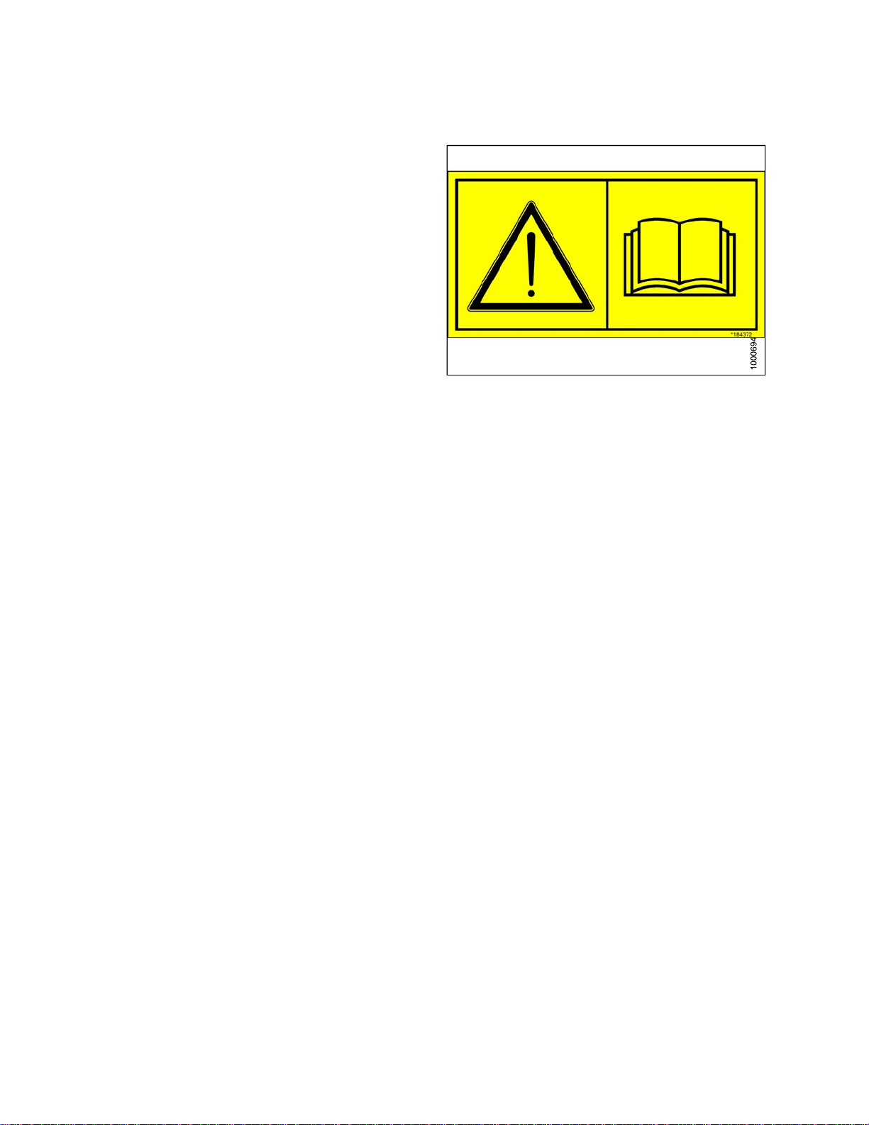
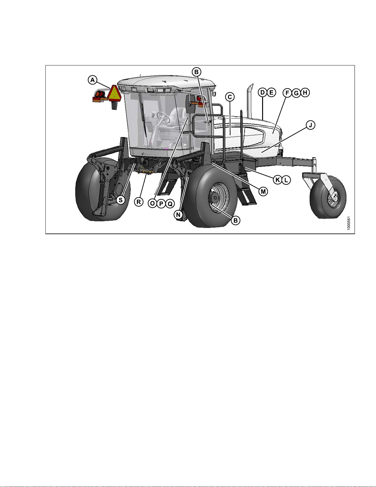
Figure 1.22: Safety Sign Locations (RH Side)
A - Hazard Sign on Seat (MD #115148) B - Lift L inkage (MD #166439) C - Frame (MD #166455)
D - Frame (MD #166456) E - Cab Frame (MD #184372) F - Platform (MD #166425)
G - Shroud (MD #166451) H - Shroud (MD #166452) J - H ydraulic Reservoir (MD #174436)
K - Wiper Cover (MD #166465) L - Rim (MD #166454 [similar to [E])
169883 1
5
Revision A
Page 32

SAFETY
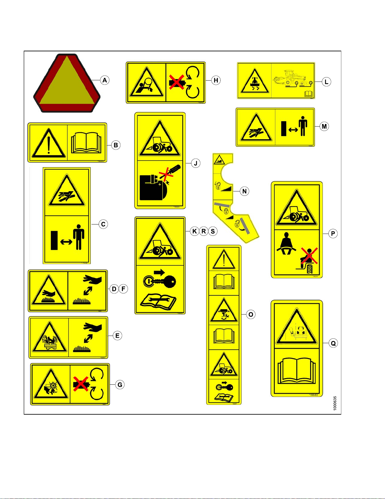
Figure 1.23: Safety Signs (RH Side)
169883 1
6
Revision A
Page 33

SAFETY
1.12 Interpreting Safety Signs
In the safety sign explanations below, (a) refers to the top or
left position panel, (b) refers to the bottom or right position
of the safety decal depending on decal orientation.
NOTE: If there are more than two panels in a decal, the
lettering will continue downward or to the right,
depending on decal orientation.
1. MD #166233
a. Run-over hazard.
b. DA NGER
• Do not start engine by shorting across starter
or starter relay terminals. Machine will start
with drive engaged and move if starting circuitry
is bypassed.
• Start engine only from operator’s seat. Do
not try to start engine with someone under or
near machine.
2. MD #166234
a. Run-over hazard.
b. WARNING
• The tra inin g seat is provided for an experienced
Operator of the machine when a new Operator
is being trained.
• The training seat is not intended as a passenger
seat or for use by children.
• Use the seat belt whenever operating the
machine or riding as a trainer.
• Keep all other riders off the machine.
Figure 1.24: MD #166233
Figure 1.25: MD #166234
169883
7
1
Revision A
Page 34

3. MD #166425
a. Roll-over hazard.
b. WARNING
• Stop the engine and remove the key from
ignition before servicing, adjusting, lubricating,
cleaning, or unplugging the machine.
4. MD #166438
a. Crushing hazard.
b. DANGER
• Rest header on ground or engage safety props
before going under unit.
SAFETY
Figure 1.26: MD #166425
169883 1
e 1.27: MD #166438
Figur
8
Revision A
Page 35

5. MD #166439
a. Crushing hazard.
b. DA NGER
• Rest header on ground or engage safety props
before going under unit.
SAFETY
6. MD #166441
a. Loss of control hazard.
b. CA UTION
• To prevent machine damage and/or loss of
control, it is essential that the machine be
equipped such that weights are within the
specified limits.
Figure 1.
Figur
28: MD #166439
e 1.29: MD #166441
169883 1
9
Revision A
Page 36

7. MD #166450
a. Hot surface hazard.
b. WARNING
• To avoid injury, keep a safe distance from
hot surface.
8. MD #166451
a. Rotating fan hazard.
b. WARNING
• To avoid injury, stop the engine and rem ove the
key before opening engine hood.
SAFETY
Figure 1.30: MD #166450
Figure 1.31: MD #166451
169883 2
0
Revision A
Page 37

9. MD #166454
a. General hazard pertaining to machine operation
and servicing.
b. CA UTION
To avoid injury or death from improper or unsafe
machine operation:
i. Read the operator’s manual and follow all
safety instructions. If you do not have a
manual, obtain one from your dealer.
ii. Do not allow untrained persons to operate
the machine.
SAFETY
iii. Review safety instructions with all
Operators annually.
iv. Ensure that all safety signs are installed
and legible.
v. Make certain everyone is clear of machine
before starting engine and during operation.
vi. Keep riders off the machine.
vii. Keep all shields in place and stay clear of
moving parts.
viii. Diseng ag e header drive, put transmission in
Neutral, and wait for all movement to stop
before leaving operator’s position.
ix. S hut off the engi ne and remove the key from
ignition before servicing, adjusting, lubricating,
cleaning, or unplugging machine.
x. Engage locks to prevent lowering of header or
reel before servicing in the raised position.
xi. Use slow m o ving vehicle em blem and flashing
warning lights when operating on roadways
unless prohibited by law.
Figure 1.32: MD #166454
10. MD #166455
a. Explosion hazard.
b. WARNING
• Prevent serious bodily injury caused by:
• Explosive battery gases. Keep sparks and
flames away from the battery. Refer to
operator’s manual for battery boosting and
charging procedures.
169883
Figure 1.
1
2
33: MD #166455
Revision A
Page 38

11. MD #166456
a. Battery acid hazard.
b. WARNING
• Corrosive and poisonous battery acid. Acid can
severely burn your body and clothing.
SAFETY
Figure 1.34: MD #166456
169883
2
2
Revision A
Page 39

12. MD #166457
a. General hazard pertaining to machine operation
and servicing.
b. CA UTION
To avoid injury or death from improper or unsafe
machine operation:
i. Read the operator’s manual and follow all
safety instructions. If you do not have a
manual, obtain one from your Dealer.
ii. Do not allow untrained persons to operate
the machine.
iii. Review safety instructions with all
Operators annually.
iv. Ensure that all safety signs are installed
and legible.
v. Make certain everyone is clear of machine
before starting engine and during operation.
vi. Keep riders off the machine.
SAFETY
vii. Keep all shields in place and stay clear of
moving parts.
viii. Diseng ag e header drive, put transmission
in Neutral and wait for all movement to stop
before leaving operator’s position.
ix. S hut off the engi ne and remove the key from
ignition before servicing, adjusting, lubricating,
cleaning, or unplugging machine.
x. Engage locks to prevent lowering of header or
reel before servicing in the raised position.
xi. Use slow m o ving vehicle em blem and flashing
warning lights when operating on roadways
unless prohibited by law.
c. Run-over hazard.
d. WARNING
• Machine will move if steering wheel is turned
while engine is running.
• Steering response is opposite to what is
normally expected wh en backing up. Turn
bottom of steering wheel in direction you want
to go.
• Always move ground speed lever to slow end of
range before shifting high-low speed control.
e. Run-over hazard.
f. Stop the engine and remove the key from ignition
before servicing, adjusting, lubricating, cleaning,
or unplugging the machine.
169883 2
Figure 1.35: MD #166457
3
Revision A
Page 40

13. MD #166461
a. Hot fluid under pressure hazard.
b. CAUTION
• Coolant is under pressure and may be hot.
Never remove radiator cap when engine is hot.
14. MD #166463
a. Collision hazard in transport.
b. WARNING
• Collision betwe en windrower and other vehicles
may result in injury or death.
SAFETY
Figure 1.36: MD #166461
When driving windrower on public roadways:
i. Obey all highway traffic regulations in your
area. Use pilot vehicles front and rear of
windrower if required by law.
ii. Use slo w moving vehicle emblem and flashing
warning lights unless prohibited by law.
iii. If width of attached header impede s other
vehicle traffic, remove header and install
MacDon approved weight box. Refer to
operator’s manual for safe procedure to tow
header.
Figure 1.37: MD #166463
169883
4
2
Revision A
Page 41

15. MD #166465
a. Loss of control hazard.
b. WARNING
To avoid serious injury or death from loss of control:
i. Do not make abrupt changes in
steering direction.
ii. Anticipate turns by slowing down well in
advance.
iii. Do not rapidly acce lera te or decelerate
while turning.
iv. Limit speed to maximum 20 mph (32 km/h)
when towing a header. To ensure steering
control refer to operator’s manual for adding
weight to drive wheels.
v. When travelling on steep slopes:
1) Reduce speed and lower header.
2) Move ground speed lever to slow end
of range.
SAFETY
Figure 1.38: MD #166465
3) Shift high-low speed control to low range.
vi. With header removed, steering control is
reduced if weight is not added to drive wheels.
If you must drive the windrower without header
or MacDon weight system:
1) Operate in low speed range.
2) Avoid slopes.
3) Do not tow a header. IF CONTROL
OF MACHINE IS LOST, IMMEDIATELY
PULL GROUND SPEED LEVER TO
NEUTRAL.
16. MD #166466
a. High pressure oil hazard.
b. WARNING
Do not go near leaks.
• High pressure oil easily punctures skin causing
serious injury, gangrene, or death.
• If injured, seek emergency medical help.
Immediate surgery is required to remove oil.
• Do not use finger or skin to check for leaks.
• Lower load or relieve hydraulic pressure before
loosening fittings.
169883 2
5
Figure 1.3
9: MD #166466
Revision A
Page 42

17. MD #174436
a. High pressure oil hazard.
b. WARNING
Do not go near leaks.
• High pressure oil easily punctures skin causing
serious injury, gangrene, or death.
• If injured, seek emergency medical help.
Immediate surgery is required to remove oil.
• Do not use finger or skin to check for leaks.
• Lower load or relieve hydraulic pressure before
loosening fittings.
18. MD #190546
a. Slippery surface.
b. WARNING
Do not place foot.
• Do not use this area as a step or platform.
SAFETY
Figure 1.40: MD #174436
• Failure to comply could result in serious injury
or death.
Figure 1.41: MD #190546
169883 2
6
Revision A
Page 43

2 Description
2.1 Definitions
The following terms and acronyms may be used in this manual.
Term Definition
A-Series header
API American Petroleum Institute.
APT articulated power turn.
ASTM American Society of Testing and Materials.
Bolt
Cab-forward Windrower operation with the Operator and cab facing in the direction of travel.
CDM Cab display module on a self-propelled windrower.
Center-link
CGVW Combined vehicle gross weight.
D-Series header
DWA Double Windrow Attachment.
ECM
Engine-forward Windrower operation with the Operator and engine facing in the direction of travel.
nger tight
Fi
F.F. F. T
MacDon auger header.
A headed and externally threaded fastener that is designed to be paired with a nut.
A hydraulic cylinder or manually adjustable turnbuckle type link between the header
and the machine to which it is attached. It is used to change header angle.
MacDon draper header.
Engine control module.
Finger tight is a reference position where sealing surfaces or components are
making contact with each other and the fitting has been tightened to a point where
the fitting is no longer loose.
Flats from finger tight.
GSL Ground speed lever.
GVW Gross vehicle weight.
Hard joint
Header
Hex key
hp Horsepower.
ISC Intermediate Speed Control.
JIC
Knife
n/a
Nut
169883
A joint made with the use of a fastener where the joining materials are
highly incompressible.
A machine that cuts and lays crop into a windrow and is attached to a
self-propelled windrower.
A hex key or Allen key (also known by various other synonyms) is a tool of
hexagonal cross-section used to drive bolts and screws that have a hexagonal
socket in the head (internal-wrenching hexagon drive).
Joint Industrial Council: a standards body that developed the standard sizing and
shape for original 37° flared fitting.
A cutting device which uses a reciprocating cutter. Also called a sickle.
Not applicable.
An internally threaded fastener that is designed to be paired with a bolt.
7
2
Revision A
Page 44

DESCRIPTION
Term Definition
N-DETENT The slot opposite the NEUTRAL position on operator’s console.
NPT
ORB
ORFS
PTO Power Take-Off.
rpm
R-Series header MacDon ro
RoHS (Reduction of
Hazardous Substances)
SAE Society Of Automotive Engineers.
Screw
Self-Propelled (SP)
Windrower
Soft joint
spm
National Pipe Thread: a style of fitting used for low pressure port openings. Threads
on NPT fittings are uniquely tapered for an interference fit.
O-ring boss: a style of fitting commonly used in port opening on manifolds, pumps
and motors.
O-ring face seal: a style of fitting commonly used for connecting hoses and tubes.
This style of fitting is also commonly called ORS, which stands for O-ring seal.
Revolutions per minute.
tary disc header.
A directive by the European Union to restrict the use of certain hazardous
substances (such as hexavalent chromium used in some yellow zinc platings).
A headed and externally threaded fastener that threads into preformed threads or
forms its own thread in one of the mating parts.
Self-propelled machine consisting of a power unit with a header and/or conditioner.
A joint made with the use o f a fastener where the joining materials are compressible
or experience relaxation over a period o f time.
Strokes per minute.
Tractor Agricultural type tractor.
uck
Tr
Tension
T.F. F.T.
Tor qu e
Torque angle
Torque-tension
UCA
Washer
Windrower
WCM
A four-wheel highway/road vehicle weighing no less than 7500 lbs (3400 kg).
Axial load placed on a bolt or screw, usually measured in pounds (lb) or Newtons (N).
Turns from finger tight.
The product of a force X lever arm length, usually measured in foot-pounds (ft·lbf)
or Newton-meters (N·m).
A tightening procedure where the fitting is assembled to a precondition (finger
tight) and then the nut is turned further a number of degrees or a number of flats to
achieve its final position.
The relationship between the assembly torque applied to a piece of hardware and
the axial load it induces in the bolt or screw.
Upper cross auger.
A thin cylinder with a hole or slot located in the center and is to be used as a spacer,
load distribution element, or a locking mechanism.
Power unit of a self-propelled header.
Windrower control module.
169883 2
8
Revision A
Page 45

2.2 Specifications
ENGINE
DESCRIPTION
Type
Displacement
Power
ELECTRICA
Recommended Battery (2)
Minimum CCA per battery
(Cold Cranking Amps)
y BCI group rating
Batter
Alternator 130 amp
Egress Lighting
Starter
ing Lights
Work
TRACTION DRIVE
e
Typ
Rated
Peak
LSYSTEM
Field
(Cab-Forward)
Cummins QSB-4.5L 4 Cylinder Turbo Diesel. B20 Biodiesel Approved.
275 cu. in. (4
148hp(110kW)@2300rpm
156hp(116kW)@2000rpm
12 Volt, Maximum Dimension: 13.25 x 7.37 x 9.44 in (334 x 188 x 232 mm).
Group Rating 29H or 31A. Heavy Duty / Off Road / Vibration Resistant.
650
29H or 31A
ard
Stand
Wet Type
11
Hydrostatic, 3 Speed Electric Shift
w Range: 0–11 mph (18 km/h),
Lo
d Range: 0–16 mph (26 km/h)
Mi
.5 L)
Speed
Transmission
Final Drive
Wheel Motor
Displacement
SYSTEM CAPACITIES
Fuel Tank
Hydraulic Reservoir 17.2 US Gallons (65 L)
HEADER DRIVE (Refer to Table 2.1 M155 Hydraulic Pumps, page 31).
Reverse
(Cab-Forward)
Transport
(Engine-Forward)
ype
T
Displacement
Flow
Pressure
Type
Ratio 30.06 : 1
Low Range
Mid Range
High Range
6mph(9.6km/h)
High Range: 0–23 mph (37 km/h)
Piston Pumps: 1 per Drive Wheel.
2
2.65 cu. in. (44 cc)
40 US gpm (167 L/min)
5500 psi (379 bar)
Planetary Gearbox
4.15 cu. in. (68 cc)
3.01 cu. in. (50 cc)
1.93 cu. in. (32 cc)
97 US Gallons (367 L)
169883 2
9
Revision A
Page 46

HEADER LIFT/TILT
DESCRIPTION
HEADER FLOAT
CAB
Type
Dimensions
Seat
ndshield
Wi
per
Wi
Type
Function
Primary
Adjustment
Fine Adjustment
Automatic
Width
Depth
Height
Volume
Driver
Training
Front
Rear
Hydraulic Dou
Optional Hydr
ble Acting Cylinders. Tilt - Optional Hy dra ulic Positioning,
aulic Center-Link
Lift/Tilt/Float
Manual, Ex
Spring On L
ternal, Drawbolt With Springs (1 per side). One Inner Booster
eft Side.
Hydraulic, In-Cab Switch
Hydraulic, 3 Programmable Settings For All Headers
(Deck Shift Compensation On Draper Headers)
Spring/Shock Suspension
63 in. (1600 mm)
n. (1735 mm) (at top of window)
68.3 i
64.6 in. (1640 mm)
125 cu. ft. (3540 L)
ustable Air-Ride Suspension, Seat Belt
Adj
Folding, Cab Mounted, Seat Belt
31.5 in. (800 mm) Blade
in. (560 mm) Blade
22
Heater
24,000 Btu/h (7038 W)
Air Conditioning 28,280 Btu/h (8288 W)
Electrical Outlets One Live, Two On Ignition, One Live/Keyed
Mirrors
Radio
One Inside (Transport), Two Outside (Field)
Two Speakers and Antenna Factory Installed. Radio Dealer Installed
SYSTEM MONITORING
Speeds
Header
Ground (mph or km/h), Engine (rpm), Knife (spm), Disc (rpm),
Reel (rpm or mph/km/h), Conveyor (Ref. No.)
Height, Angle, Float, Header Drive Load Gauge
TIRE OPTIONS (Refer to 2.2 Drive Tires, page 33 for options.)
FRAME AND STRUCTURE
Dimensions
Refer to 2.3 Windrower Dimensions, page 32
Frame to Ground (Crop Clearance) 45.7 in. (1160 mm)
1
1
1
Weight
Base
9610 lbs (4360 kg)
Maximum GVW 21,500 lbs (9750 kg)
Maximum CGVW 23,100 lbs (10,480 kg)
1. Weights do not include options.
169883 3
0
Revision A
Page 47

HEADER COMPATIBILITY
DESCRIPTION
Auger
Headers
Draper
Headers
Draper
Headers
Rotary Disc R80 and R85
A30-D, A40-D
D50, D60, and
2
D65
D60 and D65 40
2
FT
All Sizes
Up to 35 FT.
40 FT.
13 FT. Only
3
NOTE: Specifications and design are subject to change without notice or obligation to revise previously
sold units.
Table 2.1 M155 Hydraulic Pumps
Pump Type
Pump A
- Load Sense Pressure
Compensated Pis ton
Pump
Pump B
- Load Sense Pressure
Compensated Pis ton
Pump
Specifications Controller Type
Variable Displacement:
0–2.75 cu. in. (45 cc)
Flow = 0-27 gpm
(102 L/min) at 4000 psi
(27.56 MPa)
Variable Displacement:
0–2.32 cu. in. (38 cc)
Flow = 0-24 gpm
(84 L/min) at 3200 psi
(22.05 MPa)
Electric over Hydraulic
Max. Flow rate
Determined By Header ID
Electric over Hydraulic
Max. Flow rate
Determined By Header ID
Function
Knife drive or part of disc
drive (option) M1 circuit
Conveyor and reel drive or
part of disc drive (option)
M2 circuit
Pump C - Gear Pump
Pump D- Gear Pump
acement:
Displ
u. in. (13.8 cc)
0.84 c
t Full Throttle
Flow a
pm. (44 L/min) at
11. 5 g
2500 p
si (17.23 MPa)
Displacement:
0.84 cu. in. (13.8 cc)
Flow at Full Throttle
11. 5 gp m . (44 L / m i n ) at
2500 psi (17.23 MPa)
erpm
Engin
Engine rpm
Supercharge flow and
pressure for traction drive,
brake release, Neutral
lock, and DWA draper
drive (if installed).
Supercharge flow and
pressure for traction drive,
brake release, and Neutral
lock.
2. Depending on header options
3. Only 18.4 x 26 tires are compatible with the 13 FT R80 and R85
169883 3
1
Revision A
Page 48

2.3 Windrower Dimensions
DESCRIPTION
Figure 2.1: Windrower Dimensions – Forward
A - Drive Tire Tread (2.2 Drive Tires, page 33) B - Drive Tire Hubs (2.2 Drive Tires, page 33) C - Drive Tires (2.2 Drive Tires, page 33)
F - 45-3/4 in. (1160 mm) G - 133 in. (3378 mm) H - 158-5/16 in. (4022 mm)
J - 207-7/8 in. (5280 mm)
Figure 2.2: Windrower Dimensions – Reverse
D - Caster Tire Tread (2.3 Caster Tires, page 33) E - Caster Tire Casters (2.3 Caster Tires, page 33) K - 120-9/16 in. (3064 mm)
L - 186-7/8 in. (4747 mm)
169883 3
2
Revision A
Page 49

Table 2.2 Drive Tires
DESCRIPTION
Tire Size
18.4 x 26 Bar & Turf
Narrow Track
18.4 x 26
Bar and Tu
Wide Trac
600/65R28
Radial Tire
-26 and
23.1
70R26
580/
Turf
Tires
4
rf
4
k
Wheel Position
Inner/Outer
(Shipping)
Outer/Outer 130-7/8 (3324) 147-11/16 (3751) 150-5/8 (3824)
Inner/Inner 116-11/16 (2964) 133-1/2 (3391) 136-3/8 (3464)
Inner/Outer
(Shipping)
Outer/Outer 137-3/4 (3499) 147-11/16 (3751) 157-7/16 (3999)
Inner/Inner 123-9/16 (3139) 133-1/2 (3391) 143-1/4 (3639)
Inner/Outer
(Shipping)
Outer/Outer 130-11/16 (3319) 147-11/16 (3751) 155-1/16 (3938)
Inner/Inner 116-1/2 (2959) 133-1/2 (3391) 140-7/8 (3578)
Inner/Outer
(Shipping)
Outer/Outer 133-3/16 (3383) 147-11/16 (3751) 156-7/16 (3973)
Inner/Inner 119 (3023) 133-1/2 (3391) 142-1/4 (3613)
Tread (A)
in. (mm)
123-3/4 (3144) 140-9/16 (3571) 143-7/16 (3644)
130-11/16 (3319) 140-9/16 (3571) 150-3/8 (3819)
123-9/16 (3139) 140-9/16 (3571) 147-15/16 (3758)
126-1/8 (3203) 140-9/16 (3571) 149-5/16 (3793)
Hubs (B)
in. (mm)
Tires (C)
in. (mm)
Table 2.3 Caster Tires
Tire Size Wheel Position
7.5-16SL
10-16FormedCaster
10-16 Forked Caster
16.5 x 16.1
nimum
Mi
Maximum
Minimum
Maximum
Minimum
Maximum
Minimum
Maximum
Tread (D)
in. (mm)
96-7/16 (2448) 118-15/16 (3032)
35-11/16 (3448)
1
96-7/16 (2448) 118-15/16 (3032)
135-11/16 (3448) 158-3/4 (4032)
96-7/16 (2448) 118-11/16 (3014)
135-11/16 (3448) 158 (4014)
96-7/16 (2448) 118-11/16 (3014)
135-11/16 (3448) 158 (4014)
Casters (E)
in. (mm)
58-3/4 (4032)
1
4. Only 18.4 x 26 tires are compatible with the 13-foot R80 and R85.
169883 3
3
Revision A
Page 50

2.4 Component Location
DESCRIPTION
Figure 2
A - Header Lift Leg B - Header Float Springs C - Operator’s Station
D - Windshield Wiper
G - Field/Road Lights
J - Mirror K - Door
M-Cent
.3: Front Cab-Forward View
er-Link
E - Turn Signal / Hazard Lights
H - Handholds I - Tail Light Engine-Forward
F - Tail Light Engine-Forward
L - Maintenance Platform
169883 3
4
Revision A
Page 51

DESCRIPTION
Figure 2.4: Rear Cab-Forward View
A - Caster Wheel
D - Engine Compartment Hood
G - Horn H - Turn Signal/Hazard Lights
J - Door K - Drive Wheel
B - Walkin
E - Windshield Wiper
g Beam
C - Tail Lights - Cab-Forward (Option)
F - Field/Road Lights
r
I - Mirro
L - Maintenance Platform
169883 3
5
Revision A
Page 52

Page 53

3 Operator’s Station
The operator’s station is designed for operating the windrower in a cab-forward mode (working mode), or in an
engine-forward mode (transport mode). The operator’s station, which includes the seat, console, and steering
column, pivots 180 degrees so that the Operator maintains access to the windrower controls and gauges regardless
of the direction of travel.
3.1 Operator Console
The console contains controls to operate the windrower, as
well as amenities for the Operator. The console position is
adjustable to suit each particular Operator.
Figure 3.1: Operator Console
1. Adjusting fore-aft and height:
a. Pull lever (A) and slide console fore o r a ft to the
desired position.
b. Release lever to lock console.
Figure 3.2: Seat Fore-Aft
169883 3
7
Revision A
Page 54

2. Adjusting only fore-aft:
a. Loosen nuts (A) under console.
b. Move console as required.
c. Tighten nuts (A).
OPERATOR’S STATION
Figure 3.3: Seat Fore-Aft
169883 3
8
Revision A
Page 55

OPERATOR’S STATION
3.2 Operator Presence System
The Operator Presence System is a safety feature designed to deactivate or alarm selected s ystems when
the Operator is not seated at the operator’s station.
These systems include:
• Header Drive
• Engine and Transmission
3.2.1 Header Drive
• Requires the Operator to be seated in the seat in order to engage the header drive.
• Power is maintained to the header drive for five seconds after the Operator leaves the seat, and then the header
shuts down.
• After the header has shut down automatically, the HEADER DRIVE switch must be moved to OFF position and
back to the ON position again to restart the header.
3.2.2 Engine and Transmission
• The engine will not start when the HEADER DRIVE switch is engaged.
• The engine will shut down when the windrower is moving at 5 mph (8 km/h) or less and the Operator leaves the
seat. The CDM will flash “NO OPERATOR” on the upper line and “ENGINE SHUT DOWN 5...4...3...2...1...0” on
the lower line accompanied by a steady tone. At “0”, the engine shuts down.
• If the Operator leaves the seat and the transmission is not locked in NEUTRAL, after five seconds the lower
display will flash “NOT IN NEUTRAL” and an alarm will sound.
• When the seat is in between cab-forward and engine-forward positions, the engine will shut off if the transmission
is not locke d in the NEUTRAL po sition . The lower display will flash “LOCK SEAT BASE” until the seat base is
locked into position.
169883 3
9
Revision A
Page 56

OPERATOR’S STATION
3.3 Operator’s S eat Adjustments
The operator’s seat has several adjustments. Refer to the following for the location and description of
each adjustment.
3.3.1 Fore-Aft
Adjusts fore-aft position.
1. Pull lever (A) up to relea se .
2. Move seat forward or rearward.
3. Release lever (A).
3.3.2 Seat Suspension and Height
Control
INCREAS
DECREAS
s suspension stiffness and seat height.
E: Press upper switch (A).
E: Press lower switch (B).
Figure 3.4: Fore-Aft Position
Figure 3.5: Seat Suspension and Height
169883 4
0
Revision A
Page 57

3.3.3 Vertical Dampener
OPERATOR’S STATION
Adjusts suspe
INCREASE: Tur
DECREASE: Tur
nsion dampening.
n knob (A) counterclockwise.
n knob (A) clockwise.
3.3.4 Armrest
Raise armrest (A) for easier access to seat.
Lower armrest (A) after seat belt is buckled.
Figure 3.6: Vertical Dampener
169883
Figure 3.7: Armrest
1
4
Revision A
Page 58

OPERATOR’S STATION
3.3.5 Fore-Af
Locks seat fore -a ft isolator.
LOCK: Push lever (A) down.
UNLOCK: Pull lever (A) up.
tIsolatorLock
3.3.6 Seat Tilt
To adjust seat tilt:
1. Pull lever (A) up to relea se .
Figure 3.8: Fore-Aft Isolator Lock
2. Position seat back as desired.
3. Release lever (A).
Figure 3.9: Seat Tilt
169883
2
4
Revision A
Page 59

3.3.7 Armrest Angle
OPERATOR’S STATION
Adjusts angle
INCREASE: Rot
DECREASE: Rot
of armrest.
ate knob (A) clockwise.
ate knob (A) counterclockwise.
3.3.8 Lumbar Support
Adjusts stiffness of seat back.
INCREASE: Rotate knob (C) upward.
DECREASE: Rotate knob (C) downward.
Figure 3.10: Armrest Angle
169883 4
e 3.11: Lumbar Support
Figur
3
Revision A
Page 60

OPERATOR’S STATION
3.4 Training Seat
A wall mounted fold-up training seat complete with seat belt is provided.
WARNING
• The training seat is provided for an experienced Operator of the machine when a new Operator is
being trained.
• The training seat is NOT intended as a PASSENGER SEAT or FOR USE BY CHILDREN. USE THE SEAT
BELT whenever operating the machine or riding as a Trainer.
• KEEP ALL OTHER RIDERS OFF THE MACHINE.
For storage, lift seat (B) and secure with latch (A).
To lower seat, lift latch (A) and lower seat (B).
Figure 3.12: Training Seat
Figure 3.13: Training Seat
169883
4
4
Revision A
Page 61

OPERATOR’S STATION
3.5 Seat Belts
The windrower is equipped with a seat belt on the operator’s and trainer’s seats.
WARNING
• Before starting engine, securely fasten your seat belt and ensure trainer’s seat belt is fastened
if occupied.
• The seat belt can help ensure your safety if it is used and maintained.
• Never wear aseat belt loosely or with slack inthe belt system. Never wear the belt in a twisted condition
or pinched between the seat structural members.
To fasten seat belt (A):
1. Pull belt at right side completely across your body.
2. Push the metal eye (B) into the buckle (C) until it locks.
3. Adjust the position of the belt as low on your body
as possible.
To release seat belt (A):
4. Push the red button (D) in the end of the buckle.
5. Separate the buckle (C) and metal eye (B).
Figure 3.14: Seat Belt
A - Seat Belt
B - Metal Eye
C - Buckle
D - Red Button
169883 4
5
Revision A
Page 62

OPERATOR’S STATION
3.6 Steering Column Adjustment
The steering column can be adjusted to suit each particular Operator and for easier entry to and exit from the seat.
To adjust the steering column:
1. Hold onto steering wheel, lift handle (A), and move
steering wheel up or down to desired position.
2. Release handle (A) to lock steering wheel position.
Figure 3.15: Adjust Steering Column
169883 4
6
Revision A
Page 63

OPERATOR’S STATION
3.7 Lighting
The field and road light switches are located on a panel in
the cab headliner.
The lighting is dependent upon the position of the
operator’s station, that is, cab-forward mode or
engine-forward mode. The position of the operator’s
station automatically determines the lighting.
The hazard lights will be automatically activated when
certain conditions are met. The windrower must be
cab-forward, medium range, brake off, and header off.
The work lights will not turn on in certain instances. If
the wind r ower is engine-forward or if the windrower is
cab-forward, out of park, medium range, and header off.
IMPORTANT:
Red and amber reflector tape is applied
to be visible in both engine-forward and
cab-forward modes.
Figure 3.16
A - Field o r Road Lights B - Low or High Beams
C - Beacon (If Equipped)
: Roof Liner Console
3.7.1 Cab-Forward Lighting: Field
The following lights are on when the light switch is in FIELD
position with the windrower in cab-forward mode:
• Field lights in cab roof (front and rear)
• Swath lights in hood
• HID lights (if installed) on mirror supports
Figure 3.17:
Field Light Switch
169883
7
4
Revision A
Page 64

OPERATOR’S STATION
The two innermost in the field light group (A) at the front
of the cab are adjustable. Refer to Adjusting Field Lig hts,
page 339.
The two field lights (A) at the rear of the cab are adjustable.
Refer to Adjusting Rear Flood Lights, page 345.
The two swath lights (B) in th e hood are adjustable but
because they are used as road lights in engine-forward
mode and adjusted accordingly, they should NOT adjusted
for field operation.
Figure 3.18: Cab-Forward: Front View
Figure 3
.19: Cab-Forward: Rear View
169883 4
8
Revision A
Page 65

OPERATOR’S STATION
3.7.2 Engine-Forward Lighting: Road
The following lights are ON when the light switch is in
ROAD position with the windrower in engine-forward mode:
• Red tail lights (A) on the mirror supports
• Amber turn signals and hazard lights (B) on mirror
supports visible from both front and rear
• Headlights (B) in hood with low/high.
The two headlights in the hood are adjustable. Refer to
Aligning Headlights, page 335.
Figure 3.20
: Road Light Switch
Figure 3.21: Engine-Forward: Rear View
A - Red Tail Lights
B-Ambe
r Turn Signal / Hazard Lights
169883 4
Figure 3.22: Engine-Forward: Front View
A - Amber Turn Signal / Hazard Lights
B - Road Lights – Low / High
9
Revision A
Page 66

OPERATOR’S STATION
3.7.3 Cab-For
If equipped, t
switch is in th
• Four lights (A
•Amberturnsi
supports vis
• red lights (
The hazard l
certain con
cab-forwar
IMPORTANT
he following lig ht s are functional when the
e ROAD position:
) in cab roof
gnals and hazard lights (B) on mirror
ible from both front and rear
C) in hood
ights will b e autom atically activated when
ditions are met. The windrower must be
d, medium range, brake OFF, and header OFF.
:
Optional r
installed
mode compl
your MacDo
ed tail lighting and marking kit mu st be
so that road travel in the cab-forward
ward Lighting: Road ( Optional)
ies with road travel regulations. See
nDealer.
Figure 3.23: Road Light Switch
Figure
3.24: Cab Forward: Front View
169883 5
0
Revision A
Page 67

OPERATOR’S STATION
3.7.4 Beacon L
MD #B5582
The beacon lights (A) are functional when the ignition and
thebeaconswitchareON.
The beacons MUST be used when driving on the road
where required by law.
ighting: Export (N.A. Optional)
Figure 3.25: Beacon Light Switch
Figure 3.26: Cab-Forward: Front View
3.7.5 Optional HID Auxiliary Lighting (if installed)
Two optional High Intensity Discharge (HID) lights (MD #B5596) provide additional lighting during field operation.
They operate only in cab-forward mode, and if installed, are
located on the mirror supports (A).
Figure 3.27: HID Auxiliary Lights (Optional)
169883 5
1
Revision A
Page 68

OPERATOR’S STATION
If installed, they are located on the mirror supports, and are
activated with the light switch in the FIELD position.
Figure 3.28: Field Light Switch
169883 5
2
Revision A
Page 69

OPERATOR’S STATION
3.8 Windshield Wipers
The windshield wiper controls are located in the
cab he ad liner. The illustra tion shows the controls in
cab-forward mode.
Figure 3.29: Wiper Controls
A - Rear Wiper B - Front Wiper
169883 5
3
Revision A
Page 70

OPERATOR’S STATION
3.9 Rear View Mirrors
Two adjustable outside mounted mirrors (A) provide
rear view vision when the windrower is operated in
cab-forward mode.
A single interior mounted mirror (B) provides rear view
vision in the engine-forward mode.
The mirror/light as sembly (A) is designed to fold backwards
if accidentally struck either during normal operation or by
another machine. A detent-type lock keeps it in place.
Figure 3.30
: M irrors
169883 5
4
Revision A
Page 71

OPERATOR’S STATION
3.10 Cab Temperature
The cab environment is controlled by a climate control system that provides clean air-conditioned or heated air for
the Operator.
The heater/evaporator/blower assembly is located under the cab floorboard and is accessible from beneath
the windrower.
3.10.1 Heater Shut-Off
A shut-off valve (A) at the engine allows the cab heater to
be isolated from the engine coolant.
The valve must be OPEN to provide heat to the cab, but for
maximum cooling, the valve can be CLOSED.
3.10.2 Air Distribution
Cab air distribution is controlled through adjustable air
vents (A) located in the cab posts. The vents provide
window and Operator ventilation.
Figure 3.31: Heater Shut-Off Valve
re 3.32: Adjustable Air Vents
Figu
A-Vent
B - Open/Close C - Direction
169883 5
5
Revision A
Page 72

OPERATOR’S STATION
3.10.3 Contro
A–BlowerSwit
• OFF/LOW/MEDI
B – Air Condit
• OFF: A/C does
• ON: A/C opera
C–OutsideA
•FreshAir:S
drawn into c
• Recircula
is recircu
D–Tempera
• Clockwise
• Counterc
IMPORTANT:
To distribute the refrigerant oil throughout the
A/C system, perform the following steps when
starting the windrower after more than one week
of storage:
ch controls the blower speed.
ioning Switch controls A/C system.
not operate.
tes with blower switch ON.
ir Switch controls the air source.
tarts boo ster fan and filtered outsid e air is
ab.
te: Stops booster fan and cab air
lated.
ture Control Dial controls cab temperature.
: Increases temperature.
lockwise: Decreases temperature.
ls
UM / HIGH
Figure 3.33: Climate Controls
A - Blower Switch B - Air Conditioning Switch
C - Outside Air Switch D - Temperature Control Switch
1. Ensure heater s
to 3.10.1 Heate
2. Turn blower swi
temperature c
A/C control to
3. Start engine a
is warm.
4. Click A/C swi
back to OFF fo
ten times.
hut-off valve at engine is OPEN. Refer
r Shut-Off, page 55.
ontrol switch to MAXIMUM heating, and
OFF.
nd operate at low idle until engine
tch from OFF to ON for 1 second, then
r 5 to 10 seconds. Repeat this step
tch to the first position, turn
169883 5
6
Revision A
Page 73

OPERATOR’S STATION
3.11 Interior Lights
Two interior lights are installed in the cab headliner.
A low intensity LED light (A) is located directly overhead to
provide ambient lighting if desired. It functions only when
the key is in the run position . An ON-OFF switch is located
on the light.
The other interior light (B) is located on the headliner switch
panel and the push-ON, push-OFF button is located on
the light. It functions at any time.
Figure 3.34: Interior Lights
169883 5
7
Revision A
Page 74

OPERATOR’S STATION
3.12 Operator Amenities
Console
Window Shades (optional)
Figure 3.35: Console
A - Auxiliary Power Outlet
C-Cigaret
E - Utility Tray
te Lighter
B - Utility Tray under Arm Rest
D-Ashtray
/CupHolder
169883 5
Figure 3.36: Window Shades (Optional)
A - Window Shad
es (Optional)
8
Revision A
Page 75

Auxiliary Outlets
Manual Storage
OPERATOR’S STATION
Figure 3.37: Auxiliary Power Outlets
A - Auxiliary Power Outlet B - Auxiliary Power Outlet
C - Battery T
E - Switched Terminal
erminal
D - Ground Te
rminal
Coat Hook
169883 5
Figure 3.38: Operator’s Manual Storage
A - Manual Storage
Figure 3.39: Coat H
A - Coat Hook (A)
ook
9
Revision A
Page 76

OPERATOR’S STATION
3.13 Radio
A radio is available as optional equipment from your Dealer.
3.13.1 AM/FM Radio
A space (B) is provided in the cab headliner to
accommodate the installation of an AM/FM radio that is
available as optional equipment from your Dealer.
Two pre-wired speakers (A) have been factory installed in
the headliner.
For radio installation procedures, refer to MD #169885
M155 and M205 Self-Propelled Windrower Unloading
and Assembly Instructions for North A merican Shipments
or MD #169886 M-Series Self-Propelled Windrower
Unloading and Assembly Instructions for Container
Shipments.
Operating instructions are supplied with the radio.
Figure 3.4
A - Speakers
0: Speakers in Roof Liner
B - Radio Mounting Location
3.13.2 Antenna Mounting
A roof-mounted antenna base for installing a magnetic antenna is available as an option from your Dealer.
Order antenna mou nt MD #160288 (B) or see illustration for part dimensions for an improvise version. A kno ckout (C)
for the antenna lead is provided on the cab post.
IMPORTANT:
Antenna base can only be installed on the left- and right-hand rear cab roof bolts.
1. Remove existing bolt (A).
2. Install antenna mount (B) and secure with bolt (A).
169883 6
Figure 3.41: Antenna Mount
0
Revision A
Page 77

OPERATOR’S STATION
The knockout (A) is located on the exterior rig ht-hand rear
corner post of the cab, under the roof, between the horn
and the light.
To make your own mount, see template for mount.
Use11GA.or3.0mmsteelsheet.
Figure 3.42: Knockout Location in Cab
Figure 3
.43: Template for Antenna Mount
169883 6
1
Revision A
Page 78

OPERATOR’S STATION
3.14 Horn
The horn is activated by pushing the button (A) located on
the panel in the headliner.
Sound the horn three times prior to starting the engine.
The horn (A
right-han
d corner of the cab, under the roof.
) is locat ed outsid e the cab on the rear
Figure 3.44
Figure 3.45: Horn Location
: Horn Button Location
169883 6
2
Revision A
Page 79

OPERATOR’S STATION
3.15 Engine Controls and Gauges
All engine controls and gauges are conveniently located on
the operator’s console.
Refer to the illustratio n for the location and the following for
a description of each.
A – Ignition Switch
• ACC: Fully counterclockwise
• OFF: All electrical systems OFF
• RUN: Clockwise
• START: Fully clockwise to crank engine. Release and
switch returns to RUN
• REMOVE KEY WHEN WINDROWER NOT IN USE .
KEY ALSO LOCKS DOORS
B – Engine Temperature Gauge indicates engine coolant
temperature.
• Normal Running: 180°–225°F (82°–107°C)
• Warning Tone Over 230°F (110°C)
C – Fuel Gauge indic ates fue l level in tank.
•E:Empty
•F:Full
D – Throttle controls engine speed.
• FULL: Push lever forward
• OPERATING: Refer to 4.3.6Windrower Operation,page
111
• CLOSED: Pull lever back
Figure 3.46: Engine Controls and Gauges
A - Igniti on Switch B - Engine Temperature Gauge
C - Fuel Gauge
D - Throttle
169883 6
3
Revision A
Page 80

OPERATOR’S STATION
3.16 Windrower Controls
Console Controls:
A – TURN SIGNALS activate turn signals on windrower
and header.
• Push-ON / Push-OFF
B – GROUND SPEED LEVER (GSL) controls speed and
direction of movement.
•F:Forward
• N: NEUTRAL
• N-DETENT: Engages Neutral Interlock, and applies park
brake when steering locked in center
• R: Reverse
C – HAZARD WARNING LIGHTS activate signals on
windrower and header.
• Push-ON / Push-OFF
D – GROUND SPEED RAN GE SWITCH shifts
transmission speed range.
• High range: 0–23 mph (37 km/h). ENGINE-FORWARD
ONLY
• Mid range: 0–16 mph (25.7 km/h). CAB-FORWARD
ONLY
• Low range: 0–11 mph (17.7 km/h)
E – N-Detent
Autosteer Con
A – AUTOSTEER E
engages/dis
compatible s
• ENGAGE: Clic
• DISENGAGE:
trol:
NGAGEMENT SWITCH
engages the automated steering -system (if
ystem is installed).
k to engage
Turn steering wheel or click to disengage
Figure 3.47: Console Controls
169883 6
Figure 3.48: AutoSteer
A - Autosteer Engagement Switch
4
Revision A
Page 81

OPERATOR’S STATION
The autosteer engagement switch harness end (A) is
beneath the cab between the fuel tank and evaporator box.
Figure 3.49: Autosteer Harness
169883 6
5
Revision A
Page 82

OPERATOR’S STATION
3.17 Header Controls
All header controls are conveniently located on the operator’s console and on the ground speed lever (GSL) handle.
NOTE: Some controls are optional equipment and may not be present in your unit. Some controls may be
installed, but will be nonfunctional for certain headers.
Refer to spec
ific header s ections in this manual for detailed operating procedures of all header controls.
3.17.1 Heade
The header drive switch (A) engages and disengages the header drive.
To engage the header drive, push the switch to center and
pull up.
To disengage the header drive, push the switch down.
IMPORTANT:
Always move throttle lever back to IDLE before
engaging header drive. Do NOT engage header
with engine at full rpm.
r Drive Switch
Figure 3.50: Header Drive Switch
3.17.2 Header Drive Reverse Button
NOTE:
The opt
instal
andona
factor
ional hydraulic reversing kit must be
led on draper headers with a conditioner
uger headers. Rotary disc headers are
y-equipped with the reverser.
• ENGAGE: Push and hold REVERSER button (B) and
engage header with Switch (A)
• DISENGAGE: Release REVERSER Button (B)
169883 6
ure 3.51: Header Drive Switches
Fig
6
Revision A
Page 83

OPERATOR’S STATION
3.17.3 Ground
The GSL (A) con
are most often
crop conditio
tains switches for the header functions that
adjusted while in operation to suit changing
ns. All are momentary-type switches.
Speed Lever (GSL) Header Switches
NOTE: A decal (B) identifying switch functions is located
on the cab post above the operator’s console.
Figure 3.52: GSL
169883 6
Figure 3.53: GSL Function Groups
A - Reel Speed
C - Autosteer Engagement D - Display Selector
E - Header Position
B-Re
7
el Position
Revision A
Page 84

OPERATOR’S STATION
Display Selector Switch
The display selector switch (A) selects and displays the
settings in the cab display module (CDM) top line read-out
for each of the header controls.
Press switch (A) to scroll through settings.
Reel Position Switches
The reel position switches perform different functions
depending on cab display module (CDM) programming
and on which header is attached. For detailed switch
operating modes, refer to one of the following sections that
is specific to your header:
Figure 3.54: GSL
• Double Windrow Attachment (DWA) Position. Refer to
4.4.7 Double Windrowing, page 154.
• Reel Fore-Aft Position and Height on Draper Headers.
Refer to
• 4.6.4 R
• 4.6.5 R
• Center
eel Fore-Aft Position, page 229
eel Height, page 229
-Link Assist Cylinder. Refer to
• 4.5.1 Attaching a D-Series Header, page 157
• 4.5.3 Attaching an A-Series Header, page 180
Figure 3.55: Ground Speed Lever
el Down
A-Re
C - Reel Up D - Reel Aft
B-Re
el Forward
169883 6
8
Revision A
Page 85

OPERATOR’S STATION
Header Position Switches
Press and hold switch at location shown to move header
up or down and to change the angle of the header relative
to the ground. Release switch at desired position.
NOTE: Refer to the section in this manual that is
specific to your header for detailed switch
operating modes.
Reel and Disc Speed Switches
Press and hold switch at location shown to change reel or
disc speed. Release switch at desired speed.
Auger Header
• A-30 header: Not applicable
• A-40 header: Auger speed is automatically maintained
when reel speed is changed
IMPORTANT:
Reel speed on auger header MUST NOT
EXCEED 85 rpm. Auge r speed MUST NOT
EXCEED 320 rpm.
Draper Header
• Reel speed is limited in INDEX HEADER SPEED m ode
Figure 3.56: Ground Speed Lever
A - Header Down B - Header Tilt Down
C - Heade
rUp
D - Header Tilt Up
Figure 3.57: Ground Speed Lever
Rotary Disc Header
• Conditioner speed automatically adjusts when DISC
SPEED is changed
169883 6
9
Revision A
Page 86

OPERATOR’S STATION
3.17.4 Consol
e Header Switches
The operator’s console contains switches for the following header functions.
Deck Shift/Float Preset Switch
Draper Header with Deck Shift Option
• Controls deck shifting and float settings for double
windrowing options with a draper header.
Figure 3.58: Header Switches
A - Deck Shift/Float Preset Switch B - Left Side Delivery
C-Center
Delivery
D-RightS
ide Delivery
Draper Header with Fixed Decks/Auger
Header/Rotary Header
• Selects preprogrammed header float settings. Refer
to Checking Float, page 139 for instructions to pr eset
the float
NOTE: Refer to the section in this manual that is
specific to your header for detailed switch
operating modes.
Figure 3.59: Header Switches
A - Deck Shift/Float Preset Switch
C-FloatPres
et 2
B - Float Preset 1
D - Float Preset 3
169883 7
0
Revision A
Page 87

OPERATOR’S STATION
Double Windrow Attachment (DWA) / Swath Roller Switch (if installed)
Double Windrow Attachment
• The DWA deck is raised (C) or lowered (B) if switch
(A) is installed in the console and if the cab display
module (CDM) is programmed for this configuration . It
maybeusedinlieuoftheDWAswitchesontheground
speed lever (GSL).
Swath Roller
• Roller is raised (E) or lowered (D) when switch
is pressed.
NOTE:
You may swap controls to the rocker
switch or to the GSL handle, by changing
the programming in the CDM. Refer to
Detailed Programming Menu Flow Chart,
page 88.
Figure 3.60: Console Switches
169883
1
7
Revision A
Page 88

OPERATOR’S STATION
3.18 Cab Display Module (CDM)
3.18.1 Engine and Windrower Functions
Figure 3.61: CDM Engine and Windrower Functions
A – Engi
B –Grou
C –DISP
D –HAZ
E – SEL
F –TUR
G –IG
H –En
ne rpm
nd Speed: mph or kph
LAY: Engine/windrower functions.
ARD WARNING LIGHTS switch: A ctiv ates hazard warning lights, cancels turn signal.
ECT switch: Allows operator to select display item on lower line. Push to SELECT.
N SIGNAL switches: Activates turn signals on windrower and header Push-ON / Push-OFF.
NITION switch positions: Accessory / Stop / Run / Start.
gine warning lights: Engine Pre-Heat / Water In Fuel / CAUTION / Stop Engine.
169883
2
7
Revision A
Page 89

3.18.2 Header Functions
OPERATOR’S STATION
Figure 3
A – DISPLAY: Header functions.
B – SELECT SWITCH: Allows Operator to select dis pla y item on lower line. Pus h to SELECT.
C – FLOAT SWITCH – Header Right Side: Changes header float. The system remembers setting with deck shift
option if activated with float setting switch. Push + to Increase. Push – to D ecrease.
D – FLOAT SWITCH – Header Left Side: Changes header float. The system remembers setting with deck shift
option if activated with float setting switch. Push + to Increase. Push – to D ecrease.
E – AUGER/DRAPER SPEED ADJUST: Changes auger/draper speed INDEX with INDEX SWITCH ON. Changes
auger/draper SPEED with INDEX SWITCH OFF. Push upper switch to increase. Push lower switch to decrease.
F – HEADER INDEX SWITCH: Links reel and conveyor speed to ground speed. Push-ON / Push-OFF.
G –RET
.62: Cab Display Module
NOTE: Illuminates in ON position.
r must be engaged.
NOTE:
NOTE: Illum
NOTE:
Heade
URN TO CUT HEIGHT SWITC H: Allows cutting height preset. Push-ON/Push-OFF.
inates in ON position.
Header must be engaged.
169883 7
3
Revision A
Page 90

OPERATOR’S STATION
3.18.3 Operat
ing Screens
The cab display module (CDM) and the windrower control module (WCM) provide information on several functions
for the engine, header, and windrower. The information displayed in various operating modes is described in the
following sections.
Figure 3.63: CDM Operating Screen
lay
A - Display Selector for Upper Line
D - CDM Lower Line E - Display Selector for Lower Line
B-Disp
C - CDM Upper Line
Ignition ON, Engine Not Running
Display (upper line) (2–3 seconds) Description
HEADER DISENGAGED Indicates HEADER DRIVE switch is OFF.
IN PARK Indicates hround speed lever (GSL) is in N-DETENT.
169883
4
7
Revision A
Page 91

OPERATOR’S STATION
Engine-Forward, Engine Running
Display Description
ROAD GEAR (Upper Line) Ground speed range switch in high range.
#####.# ENGINE HRS (Upper or Lower Line)
#####.# HEA
###### TOTAL ACRES (Upper or Lower Line)
###### TOTAL HECT (if Metric)
##.# HEADER HEIGHT (Upper or Lower Line) Distance setting (00.0–10.0) between cutterbar and ground.
##.# HEAD
### °C or F HYD OIL TEMP
##.# VOLTS (Upper or Lower Line)
SCROLL
DER HRS (Upper or Lower Line) Total header operating time.
ER ANGLE (Upper or Lower Line)
(Lower Line)
Total engine operating time.
Total area cut by machine.
Angle set
Hydraulic oil temperature.
Engine electrical system operating voltage.
Displa
to canc
ting (00.0–10.0) header relative to ground.
ys above items after 2–3 seconds; press SELECT
el.
Cab-Forward, Engine Running, Header Disengaged
Scroll through display with cab display module (CDM) switch or ground speed lever (GSL) switch.
Display (lower or upper line) Description
#####.# ENGINE HRS
#####.# HEADER HRS
###.# SUB ACRES
###.# SUB HECTARES (if metric)
Total engine operating time.
Total header operating time.
Area cut since last reset. To reset, display SUB ACRES
on lower line, and hold down Program switch until display
resets (5–7 seconds).
###### TOTAL ACRES
###### TOTAL HECT (if metric)
##.# HEADER HEIGHT Distance setting (00.0–10.0) between cutterbar and ground.
##.# HEADER ANGLE Angle setting (00.0–10.0) header relative to ground.
##.# L FLOAT R ##.# Float setting (0.0–10.0).
### °C or F HYD OIL TEMP
##.# VOLTS
SCROLL (Lower Line)
169883 7
Total area cut by machine.
Hydraulic oil temperature.
Engine electrical system operating voltage.
Displays above items after 2–3 seconds; press SELECT
to cancel.
5
Revision A
Page 92

OPERATOR’S STATION
Cab-Forward, Engine Running, Header Engaged, Auger Header Index Switch OFF
Scroll through display with cab display module (CDM) switch or ground speed lever (GSL) switch.
Display (lower or upper line) Description
#####.# ENGINE HRS
#####.# HEADER HRS
##.# ACRES/HOUR
##.# HECTARES/HOUR (If Metric)
###.# SUB ACRES
###.# SUB HECTARES (If Metric)
###### TOTAL ACRES
###### TOTAL HECT (If Metric)
##.## REEL RPM
##.## REEL SENSOR
##.# AUGER SPEED Auger rotational speed (4.7–9.9).
#### KNIFE SPEED
#### KNIFE SENSOR
##.# HEADER H EIGHT
##.# HEADER SENSOR
##.# HEADER A NGLE
##.# HEADER SENSOR
Total engine operating time.
Total header operating time.
Actual cutting rate in acres (hectares)/hour.
Area cut since last reset. To reset, display SUB ACRES
on lower line, and hold down program switch until display
resets (5–7 seconds).
Total are a cut by machine.
Reel rotational speed.
Sensor Disabled. RPM and SENSOR alternate at 1 second
intervals.
Knife speed in strokes per minute.
Sensor Disabled. SPEED and SENSOR alternate at
1 second intervals.
Distance setting (00.0–10.0) between cutterbar and ground.
Sensor Disabled. HEIGHT and SENSOR alternate at
1 second intervals.
Angle setting (00.0–10.0) header relative to ground.
Sensor Disabled. ANGLE and SENSOR alternate at
1 second intervals.
##.# L FLOAT R ##.#
FLOAT SENS DISABLED
LOAD|■■■■||####
### °C or F HYD OIL TEMP
###°CorFHYDTEMP
##.# VOLTS
SCROLL
SUB-MENU (Lower Line Only)
#### KNIFE SPEED
##.# HEADER H EIGHT
LOAD|■■■■|■■■■| ####
5. The LOAD sensorto monitor knife/conditioner circuit pressure is optional. Tomonitor reel/auger circuit pressure, relocate
sensor as per Form MD #169031, which is available through your Dealer.
169883 7
Left and right float setting (0.0–10.0).
Sensor Disabled.
Bar graph representing hydraulic operating pressure. Full
scale is preprogrammed overload pressure (2500–5000
psi). If sensor disabled, LOAD does not display
Hydraulic oil temperature.
Sensor Disabled. TEMP and SENSOR alternate at
1 second intervals.
Engine electrical system operating voltage.
Displays sub-menu after 2–3 seconds. Press SELECT to
cancel. Scroll through sub-menu display with CDM switch.
6
5
.
Revision A
Page 93

OPERATOR’S STATION
Cab-Forward, Engine Running, Header Engaged, Auger Header Index Switch ON
Scroll through display with cab display module (CDM) switch or ground speed lever (GSL) switch.
Display (lower or upper line) Description
#####.# ENGINE HRS
#####.# HEADER HRS
##.# ACRES/HOUR
##.# HECTARES/HOUR (If Metric)
###.# SUB ACRES
###.# SUB HECTARES (If Metric)
###### TOTAL ACRES
###### TOTAL HECT (If Metric)
##.## ##.# REEL IND.
##.## REEL SENSOR
##.# AUGER SPEE D
##.# AUGER SENSOR
#### KNIFE SPEED
#### KNIFE SENSOR
##.# HEADER HEIGHT
##.# HEADER SENSOR
Total engine operating time.
Total Header operating time.
Actual cutting rate in acres (hectares)/hour.
Area cut since last reset. To reset, display SUB ACRES
on lower line, and hold down program switch until display
resets 5–7 seconds).
Total area cut by machine.
Reel Peripheral speed along with ground speed in mph or
kph.
Sensor disabled. IND and SENSOR alternate at 1 second
intervals.
Auger rotational speed (4.7–9.9).
Sensor disabled. SPEED and SENSOR alternate at
1 second intervals.
Knife speed In strokes per minute.
Sensor disabled. SPEED and SENSOR alternate at
1 second intervals.
Distance setting (00.0–10.0) between cutterbar and ground.
Sensor disabled. HEIGHT and SENSOR alternate at
1 second intervals.
##.# HEADER ANGLE
##.# TILT SENSOR
##.# L FLOAT R ##.#
FLOAT SENS DISABLED (If Sensor Disabled)
LOAD|■■■■||####
### °C or F HYD OIL TEMP
### °C or F HYD TEMP
6. The LOAD sensor to m onitor knife/conditioner circu it pressureis optional. Tomonitor reel/auger circuit pressure, relocate
sensor as per Form MD #169031, which is available through your Dealer.
Angle setting (00.0–10.0) header relative to ground.
Sensor disabled. ANGLE and SENSOR alternate at
1 second intervals.
Left and right float setting (0.0–10.0).
Sensor disabled.
Bar graph representing hydraulic operating pressure. Full
scale Is preprogrammed overload pressure (2500–5000
psi). If sensor disabled, LOAD does not display
Hydraulic oil temperature.
Sensor Disabled. TEMP and SENSOR alternate at
1 second intervals.
6
169883
7
7
Revision A
Page 94

OPERATOR’S STATION
Display (lower or upper line) Description
##.# VOLTS
SCROLL
SUB-MENU (Lower Line Only)
#### KNIFE SPEED
##.# HEADER H EIGHT
LOAD|■■■■|■■■■| ####
Engine electrical system operating voltage.
Displays sub-menu after 2–3 Seconds. Press SELECT to
cancel. Scroll through sub-menu display with CDM switch.
Cab-Forward, Engine Running, Header Engaged, Draper Header, Index Switch OFF
Scroll through display with cab display module (CDM) switch or ground speed lever (GSL) switch.
Display (lower or upper line) Description
#####.# ENGINE HRS
#####.#
##.# ACRES/HOUR
##.# HECTARES/HOUR (if metric)
###.# SUB ACRES
###.# SUB HECTARES (if metric)
#####
#####
HEADER HRS Total header operating time.
# TOTAL ACRES
#TOTALHECT(ifmetric)
Total engine operating time.
Actual cutting rate in acres (hectares)/hour.
Area cut since last reset. To reset, display SUB ACRES
on lower line, and hold down program switch until display
resets (5–7 seconds).
Total are a cut by machine.
##.## REEL MPH
##.## REEL KPH (if metric)
##.## REEL SENSOR (flashing)
# DRAPER SPEED
##.
#### KNIFE SPEED
#### KNIFE SENSOR
##.# HEADER H EIGHT
##.# HEADER SENSOR
#.# HEADER A NGLE
#
##.# HEADER SENSOR
##.# L FLOAT R ##.#
FLOAT SENS DISABLED
### °C or F HYD OIL TEMP
### °C or F HYD SENSOR
Reel peripheral speed.
Sensor Disabled. MPH or KPH and SENSOR alternate
at 1 second intervals.
per speed (0.0–11.0).
Dra
Knife speed In strokes per minute.
Sensor Disabled. SPEED and SENSOR alternate at
1 second intervals.
Distance setting (00.0–10.0) between cutterbar and ground.
Sensor Disabled. HEIGHT and SENSOR alternate at
1 second intervals.
ngle setting (00.0–10.0). Header relative to ground.
A
Sensor Disabled. ANGLE and SENSOR alternate at
1 second intervals.
Left and right float setting (0.0–10.0).
Sensor Disabled.
Hydraulic oil temperature.
Sensor Disabled. TEMP and SENSOR alternate at
1 second intervals.
169883 7
8
Revision A
Page 95

OPERATOR’S STATION
Display (lower or upper line) Description
LOAD|■■■■||####
##.# VOLTS Engine elect
SCROLL
SUB-MENU (Lower Line Only)
#### KNIFE SPEED
##.# HEADER HEIGHT
LOAD|■■■■|■■■■| ####
##.## REEL MPH
##.# DRAPER SPEED
KNIFE SPD OVERLOAD
Bar graph representing hydraulic operating pressure.
Full scale is pre-programmed overload pressure
(2500–5000 psi). If sensor disabled, LOAD does not
display
Displays sub-menu after 2–3 seconds. Press SELECT to
cancel. Scroll through sub-menu display with CDM switch.
7
rical system operating voltage.
Cab-Forward, Engine Running, Header Engaged, Draper Header, Index Switch ON
Scroll through display with cab display module (CDM) switch or ground speed lever (GSL) switch.
Display (lower or upper line) Description
ngine operating time.
#####.# ENGINE HRS
.# HEADER HRS
#####
Tot al e
Total header operating time.
##.# ACRES/HOUR
##.# HECTARES/HOUR (if metric)
###.# SUB ACRES
###.# SUB HECTARES (if metric)
### TOTAL ACRES
###
### TOTAL HECT (if metric)
###
##.## ##.# REEL IND
REEL.SENSOR
#.# ##.# DRAP INDX
#
#### KNIFE SPEED
#### KNIFE SENSOR
##.# HEADER HEIGHT
##.# HEADER SENSOR
##.# HEADER ANGLE
##.# HEADER SENSOR
Actual cutting rate in acres (hectares)/hour.
Area cut since last reset. To reset, display SUB ACRES
on lower line and hold down program switch until display
resets (5–7 Seconds).
Total area cut by machine.
Reel peripheral speed along with ground speed in mph or
kph.
Sensor Disabled. IND and SENSOR alternate at 1 second
intervals.
raper speed along with ground speed in mph or kph.
D
Knife speed in strokes per minute. Sensor Disabled.
SPEED and SENSOR alternate at 1 second intervals.
Distance setting (00.0–10.0) between cutterbar and ground.
Sensor Disabled. HEIGHT and SENSOR alternate at 1
second intervals.
Angle setting (00.0–10.0) header relative to ground.
Sensor Disabled. ANGLE a n d SENSOR alternate at 1
second intervals.
7. The LOAD sensor to monitor knife/conditioner circuit pressure is optional. Tomonitor reel/auger circuit pressure, relocate
sensor as per Form MD #169031, which is available through your Dealer.
169883 7
9
Revision A
Page 96

OPERATOR’S STATION
Display (lower or upper line) Description
##.# L FLOAT R ##.#
FLOAT SENS DISABLED
LOAD|■■■■||####
##.# VOLTS
SCROLL
SUB-MENU (lower line only)
#### KNIFE SPEED
##.# HEADER H EIGHT
LOAD|■■■■|■■■■|
##.## ##.# REEL IND
##.# ##.# DRAP INDX
##.## REEL MIN RPM (lower line)
MINIMUM (lower line)
Left and right float setting (0.0–10.0).
Sensor Disabled.
Bar graph representing hydraulic operating pressure. Full
scale is pre-programmed overload pressure (2500–5000
psi). If sensor disabled, LOAD does not display
Engine electrical system operating voltage.
Displays sub-menu after 2–3 seconds. Press SELECT to
cancel.
Scroll through sub-menu display with CDM switch.
Reel speed drops below programmed set-point.
Reel speed at zero ground speed.
Cab-Forward, Engine Running, Header Engaged, Rotary Header Installed
Scroll through display with cab display module (CDM) switch or ground speed lever (GSL) switch.
ay (lower or upper line)
Displ
Descr
iption
8
#####.# ENGINE HRS
#####.# HEADER HRS
# ACRES/HOUR
##.
# HECTARES/HOUR (If Metric)
##.
###.# SUB ACRES
###.# SUB HECTARES (If Metric)
###### TOTAL ACRES
###### TOTAL HECT (If Metric)
### DISC RPM
#
#.## DISC SENSOR
#
##.# HEADER H EIGHT
##.# HEIGHT SENSOR
##.# HEADER A NGLE
##.# HEADER SENSOR
##.# L FLOAT R ##.#
FLOAT SENS DISABLED
Total engine operating time.
l header operating time.
Tot a
ual cutting rate in acres (hectares)/hour.
Act
Area cut since last reset. To reset, display SUB ACRES
on lower line, and hold down program switch until display
resets (5–7 seconds).
tal area cut by machine.
To
Disc rotational speed.
Sensor Disabled. RPM and SENSOR alternate at 1 second
intervals.
Distance setting (00.0–10.0) between cutterbar and ground.
Sensor Disabled. HEIGHT and SENSOR alternate at
1 second intervals.
Angle setting (00.0–10.0) header relative to ground.
Sensor Disabled. ANGLE and SENSOR alternate at
1 second intervals.
Left and right float setting (0.0–10.0).
Sensor Disabled.
8. The LOAD sensorto monitor knife/conditioner circuit pressure is optional. Tomonitor reel/auger circuit pressure, relocate
sensor as per Form MD #169031, which is available through your Dealer.
169883 8
0
Revision A
Page 97

OPERATOR’S STATION
Display (lower or upper line) Description
LOAD|■■■■||####
Bar graph representing hydraulic operating pressure. Full
scale is pre-programmed overload pressure (2500–5000
psi). If sensor disabled, LOAD does not display
### °C or F HYD OIL TEMP
### °C or F HYD TEMP
Hydraulic oil temperature.
Sensor Disabled. TEMP and SENSOR alternate at
1 second intervals.
##.# VOLTS
SCROLL
SUB-MENU (Lower Line Only)
Engine electrical system operating voltage.
Displays sub-menu after 2–3 seconds. Press SELECT to
cancel. Scroll through sub-menu display with CDM switch.
#### DISC RPM
##.# HEADER HEIGHT
LOAD|■■■■|■■■■|####
Miscellaneous Operational Information
Scroll through display with cab display module (CDM) switch or ground speed lever (GSL) switch.
Display (upper line) Description
HEADER
##.# FOOT DISK
DISENGAGED Header drive is disengaged.
AUGER or DRAPER will appear in place of DISK,
depending on type of header attached.
9
.
IN PARK
<LEFTTURN■
■ RIGHT TURN >
ZARD ■
■ HA
HEADER REVERSE
HEADER ENGAGED
OAD GEAR
R
GSL in N-DETENT position.
cates left turn when left arrow is pressed on CDM.
Indi
ne-forward mode only
Engi
10
.
Indicates right turn when right arrow is pressed on CDM.
Engine forward mode only
icates hazard warning lights are on when hazard button
Ind
ressed on CDM.
is p
11
Header drive running in reverse.
Header drive engaged.
ith HIGH RANGE selected on Console switch.
W
ngine-forward only
E
11
9. The LOAD sensor to monitor knife/conditioner circuit pressure is optional-installed. Tomonitor reel/auger circuit pressure,
relocate sensor as per Form MD #169031, which is available through your Dealer.
10. If roa d light kit is not installed, CDM will display E135 LEFT STOP LAMP as a malfunction in CAB-FORWARD m ode.
11. If road lightkit is not installed, CDM will displayE134 RIGHT STOP LAMP asa malfunction in CAB-FORWARD mode.
169883 8
1
Revision A
Page 98

OPERATOR’S STATION
3.18.4 Cab Dis
The CDM displays warnings and sounds alarms to notify of abnormal windrower status at startup when the ignition
is turned ON, and at engine operating speeds above 500 rpm.
play Module (CDM) Warning/Alarms
Engine Warning Lights
Figure 3.64: CDM Engine Warning Lights
A – ENGINE PRE-HEAT: Illuminates yellow. Wait to start engine.
B – WATER IN FUEL: Illuminates yellow. Service recommended.
C – CAUTION: Illuminates yellow. Prompt attention is required. Refer to display code.
D – STOP: Illuminates red. Stop engine immediately. Refer to display code.
E – DISPLAY: Displays malfunction code. Refer to 8 Engine Error Codes, page 411 or Dealer.
169883 8
2
Revision A
Page 99

OPERATOR’S STATION
Display Warnings and Alarms
Informs Operator of abnormal windrower conditions.
Figure 3.65: CDM Display Warnings and Alarms
Display (A) Flashing Alarm Tone Description
BRAKE OFF
BRAKE ON
BRAKE SW FAILURE X Short Beep with Each Flash.
CAB-FORWARD SW ON/
ENG-FORWARD SW ON
CENTER STEERING Beeps at 2 Per Second.
DISENGAGE HEADER
RE-ENGAGE
<1800RPM>
ENGINE AIR FILTER
X
X
X Messages Flash Alternately.
XNo
X
Short Beep with Each Flash.
Short Beep with Each Flash.
ne
Single Loud Tone for 10
Seconds. Repeats Every 30
Minutes Until Condition Is
Corrected.
Engine Running, Brake Solenoid
Not Activated.
Ground speed lever (GSL) out of
N-DETENT, but Interlock Switch
Remains Closed to Apply Brak e.
Ignition ON / Engine Not Running,
Brake Switch and Relay Closed.
Both Seat Switches Activated.
GSL or Interlock Switches not
Closed with Key ON / Engine OFF.
R80/R85 - Engine rpm Above
1800 when Engaging Header.
Engine Air Filter Requ ires
Servicing.
169883 8
3
Revision A
Page 100

OPERATOR’S STATION
Display (A) Flashing Alarm Tone Description
Ongoing Intermittent Moderate
ENGINE TEMPERAT URE
HEADER DISENGAGED
DISENGAGE HEADER X None
HEADER OIL PRESS
HYDRAULIC FILTER
### °C or F HYD OIL
COLD
### °C or F HYD OIL HOT
X
X
X
X
X
Tone until Temperature Is Below
215°F (102°C).
None Normal
Continuous Loud Tone until Oil
Pressure Is Regained.
Single Loud Tone for 10
Seconds. Repeats Every
15 Minutes until Condition Is
Corrected.
Tone Sounds with Each Flash
for 5 Seconds and then
Stops for 1 Minute. Flashing
Continues. If Oil Still Cold after
1 Minute, Tone Sounds Again.
Tone with Each Flash at 220°F
(105°C) for 5 Seconds and Then
Stops for 1 Minute. Flashing
Continues. If Oil Still Hot after
1 Minute, Tone Sounds Again.
Flashing and Steady Tone at
230°F (110°C) and Higher.
Engine Temperature Over 230°F
(110°C).
HeaderSwitchIsinONPosition
when Ignition Switch Turned ON.
Low Header Charge Oil
Pressure. Header Shuts Down
Automatically. Head er ON Switch
Must be Moved to OFF Position
and Then to ON Position to
Restart the Header.
Excessive Pressure Increase
across Hydraulic Oil Filter.
Hydraulic Oil Temp <50°F (10°C).
Hydraulic Oil Temp >220°F
(105°C) but <230°F (110°C).
IN PARK X
KNIFE SPEED
OVERLOAD
LOCK SEAT BASE
LOW HYDRAULIC OIL
NO HEADER
169883 8
X
X None
X
One Short Beep.
Short Beep With Each Flash
Until Condition Is Corrected.
Continuous Loud Tone for 5
Seconds. If Condition not
Rectified, Single Loud Tone
Every 5 Minutes.
None Header Is Not Detected.
GSL In N-DETENT, Steering
Wheel Centered, and Brakes Are
Engaged.
Machine Overload. Knife or Disc
Speed Drops Below Programmed
Value.
Seat Base not Detected In Cab or
Engine-Forward Position.
Low Hydraulic Oil Level. Header
Shuts Down Automatically if
Engaged. Header ON Switch
Must Be Moved to OFF Position
and then to ON Position to Restart
the Header.
4
Revision A
 Loading...