

MacDon FlexDraper FD1, FM100, FlexDraper FD145, FlexDraper FD130, FlexDraper FD135 Operator's Manual
...Page 1

FD1 Series
FlexDraper
®®
Combine Header
Operator ’s Manual
214683 Revision A
2019 Model Year
Original Instruction
Featuring MacDon FLEX-FLOAT Technology™
The harvesting specialists.
Page 2
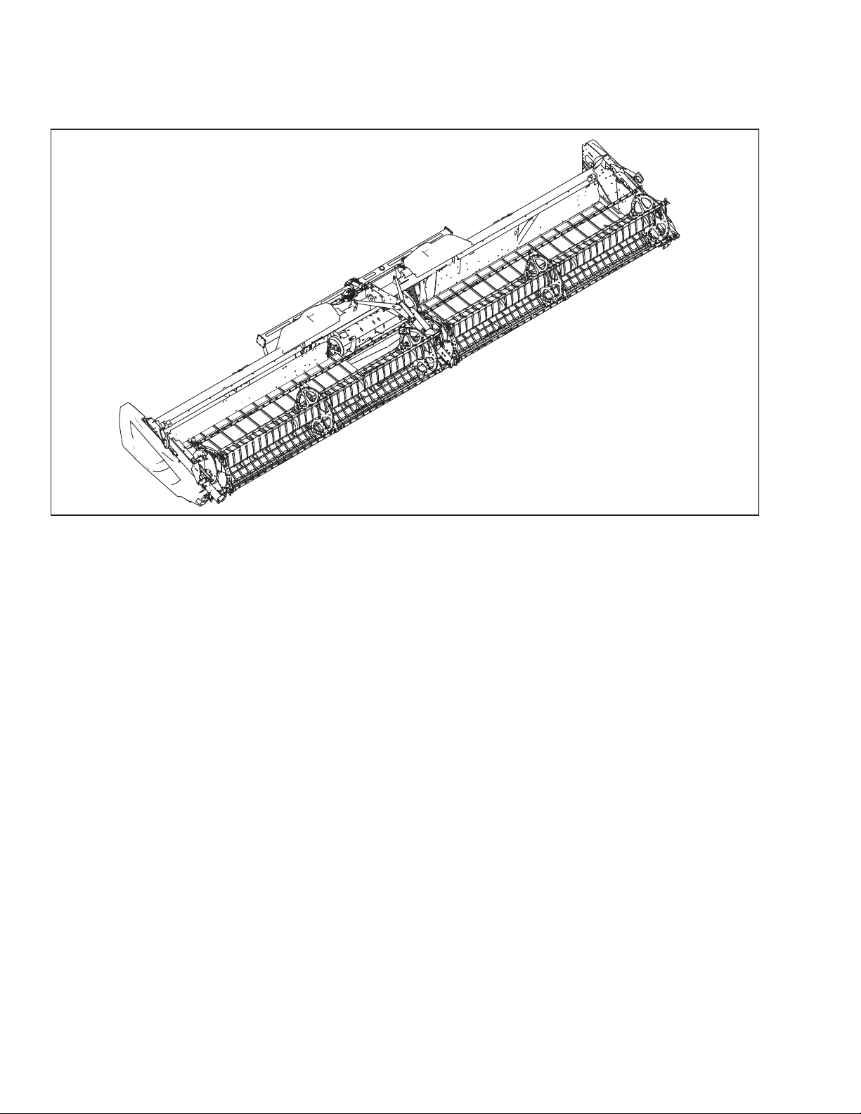
FD1 Series FlexDraper®Header
1016679
Published: June 2018
Page 3

Declaration of Conformity
1026043
214683 i Revision A
Page 4

1026044
214683 ii Revision A
Page 5

1026045
214683 iii Revision A
Page 6

1026044
214683 iv Revision A
Page 7

Introduction
This instructional manual contains information on the FD1 Series FlexDraper®and the FM100 Combine Float
Module. It must be used in conjunction with your combine operator's manual.
®
The FD1 Series FlexDraper
above the ground, using a three-piece flexible frame to closely follow ground contours. The FM100 Combine Float
Module is used to attach an FD1 Series FlexDraper
Carefully read all the material provided before attempting to use the machine.
Use this manual as your first source of information about the machine. If you follow the instructions provided, your
header will work well for many years. If you require more detailed service information, a technical manual is
available from your MacDon Dealer.
MacDon provides warranty for Customers who operate and maintain their equipment as described in this manual.
A copy of the MacDon Industries Limited Warranty Policy, which explains this warranty, should have been provided
to you by your Dealer. Damage resulting from any of the following conditions will void the warranty:
• Accident
• Misuse
• Abuse
• Improper maintenance or neglect
• Abnormal or extraordinary use of the machine
is specially designed to work well in all straight cut conditions, whether cutting on or
®
to most makes and models of combines.
• Failure to use the machine, equipment, component, or part in accordance with the manufacturer’s instructions
The following conventions are used in this document:
• Right and left are determined from the operator’s position. The front of the header faces the crop; the back of
the header attaches to the combine.
• Unless otherwise noted, use the standard torque values provided in Chapter 8.1 Torque Specifications, page
577.
When setting up the machine or making adjustments, review and follow the recommended machine settings in all
relevant MacDon publications. Failure to do so may compromise machine function and machine life and may result
in a hazardous situation.
The Table of Contents and Index will guide you to specific areas of this manual. Study the Table of Contents to
familiarize yourself with how the information is organized.
214683 v Revision A
Page 8

1024245
A
Keep this manual handy for frequent reference and to pass
on to new Operators or Owners. A manual storage case (A)
is located inside the header left endshield.
Call your MacDon Dealer if you need assistance,
information, or additional copies of this manual.
NOTE:
Keep your MacDon publications up-to-date. The most
current version can be downloaded from our website
(www.macdon.com) or from our Dealer-only site
(https://portal.macdon.com) (login required).
This document is available in English, Czech, German,
French, Portuguese, Russian, and Ukrainian.
Figure 1. Manual Storage Location
214683 vi Revision A
Page 9

List of Revisions
Summary of Change Refer To
Updated Declaration of Conformity for model
year 2019.
Added Ukrainian to the list of languages available.
Added FM100 safety decal locations. 1.7 Safety Decal Locations, page 8
Added safety decal MD #252996. 1.8 Understanding Safety Signs, page 13
Updated illustrations of endshield hinge plate. Added
note to ensure hinge arm is installed in outboard hole
on the hinge bracket.
Updated illustrations to show transport lights.
Revised the high voltage limit adjustment instructions.
Added topic.
Added step and image showing the header
control switch.
Added settings for HEIGHT/TILT RESPONSE and
AUTO HEIGHT OVERRIDE.
Declaration of Conformity, page i
Introduction, page v
• Removing Endshields, page 36
• Installing Endshields, page 37
Repositioning Fore-Aft Cylinders on Non-EuropeanConfigured Headers with Multi-Crop Rapid Reel
Conversion Option, page 108
Adjusting Voltage Limits: One-Sensor System, page
131
Replacing Float Indicator Cable, page 135
Calibrating Auto Header Height Control (Case IH 5130/
6130/7130, 5140/6140/7140), page 146
Calibrating the Auto Header Height Control (Case
Combines with Version 28.00 or Higher Software),
page 160
Added settings specific to the two-sensor system.
Added steps to set center link to D, unlock float, and
lock wings.
Added steps for calibrating feeder house speed.
Removed unnecessary steps involving header float;
these steps are not applicable to reel height sensor
calibration.
Deleted note with link to height sensor adjustment; the
note isn’t relevant to feeder house speed calibration.
Added step to lock wings before calibration.
• Setting up the Header on the Combine Display
(Case IH 5130/6130/7130; 5140/6140/7140), page
142
• Calibrating the Auto Header Height Control
(Case IH 7010/8010, 7120/8120/9120,
7230/8230/9230, 7240/8240/9240), page 156
• Calibrating the Auto Header Height Control (Case
Combines with Version 28.00 or Higher Software),
page 160
Calibrating the Auto Header Height Control (Case
Combines with Version 28.00 or Higher Software),
page 160
Calibrating the Auto Header Height Control (John
Deere S and T Series), page 215
Calibrating Reel Height Sensor (John Deere S and T
Series), page 227
Calibrating Feeder House (John Deere S7 Series),
page 236
Calibrating the Auto Header Height Control (CLAAS
600 and 700 Series), page 251
214683 vii Revision A
Page 10

Added topics.
• Calibrating Reel Height Sensor (CLAAS 600 and
700 Series), page 258
• Adjusting Auto Reel Height (CLAAS 600 and 700
Series), page 260
Revised caution statement about reduced header
stability when cornering.
• Removed mentions of discontinued flighting
bundles B6215 and B6216.
• Updated feed auger illustrations.
Updated feed auger illustrations.
• Added changing oil in header drive gearbox (first 50
hours only).
• Added lubricating center draper roller bearings
(every 50 hours).
• Added checking draper roller bearings for heat
(every 200 hours)
Towing the Header, page 291
4.1 Float Module Feed Auger Configurations, page 307
• 5.7.2 Checking Auger Drive Chain Tension, page
421
• 5.7.3 Adjusting Auger Drive Chain Tension, page
423
• 5.7.4 Removing Auger Drive Chain, page 424
• 5.7.5 Installing Auger Drive Chain, page 426
5.3.1 Maintenance Schedule/Record, page 385
Added checking and adjusting finger timing
instructions.
Revised topic—No adjustment is required if spring
retainers are within +6 to –3 of flush and feed draper is
tracking properly.
Updated torque value for center reel arm brace bolts.
Updated illustration to show new bolt orientation.
Updated reel speed sensor illustrations.
Updated load range D tire pressure to 75 psi.
Added topics.
• Checking Auger Finger Timing, page 434
• Adjusting Auger Finger Timing, page 435
5.10.2 Adjusting Feed Draper Tension, page 468
5.15.3 Centering Double Reel, page 507
• Replacing AGCO (Challenger, Gleaner, and
Massey Ferguson) Sensor, page 538
• Replacing John Deere Reel Speed Sensor, page
540
5.17.3 Checking Tire Pressure, page 544
• 6.4.6 Center Skid Shoes Kit, page 554
• 6.5.9 European Combine Upper Cross Auger
(UCA), page 559
214683 viii Revision A
Page 11

Model and Serial Number
1020884
A
1020665
A
Record the model number, serial number, and model year of the header, combine float module, and
transport / stabilizer wheel option (if installed) in the spaces provided.
NOTE:
Right and left designations are determined from the operator’s position, facing forward.
®®
FlexDraper
Header Model:
Serial Number:
Year:
The serial number plate (A) is located in the upper corner
on the left endsheet.
Header
Figure 2. Header, Left Side Endshield
Combine Float Module
Float Module
Model:
Serial Number:
Year:
The serial number plate (A) is located at the top left side
of the float module.
Figure 3. Float Module
214683 ix Revision A
Page 12

1005072
A
Slow Speed Transport / Stabilizer Wheel Option
Serial Number:
Year:
The serial number plate (A) is located on the right axle
assembly.
Figure 4. Transport/Stabilizer Option
214683 x Revision A
Page 13

TABLE OF CONTENTS
Declaration of Conformity............................................................................................................................ i
Introduction...............................................................................................................................................v
List of Revisions ...................................................................................................................................... vii
Model and Serial Number.......................................................................................................................... ix
Chapter 1: Safety .................................................................................................................................... 1
1.1 Safety Alert Symbols ............................................................................................................................1
1.2 Signal Words .......................................................................................................................................2
1.3 General Safety.....................................................................................................................................3
1.4 Maintenance Safety .............................................................................................................................5
1.5 Hydraulic Safety...................................................................................................................................6
1.6 Safety Signs ........................................................................................................................................7
1.6.1 Installing Safety Decals ...............................................................................................................7
1.7 Safety Decal Locations.........................................................................................................................8
1.8 Understanding Safety Signs................................................................................................................ 13
Chapter 2: Product Overview ............................................................................ ................................ 19
2.1 Definitions .........................................................................................................................................19
2.2 Specifications ....................................................................................................................................21
2.3 Component Identification ....................................................................................................................25
®
2.3.1 FD1 Series FlexDraper
2.3.2 FM100 Float Module..................................................................................................................26
............................................................................................................25
Chapter 3: Operation ...........................................................................................................................29
3.1 Owner/Operator Responsibilities.........................................................................................................29
3.2 Operational Safety .............................................................................................................................30
3.2.1 Header Safety Props .................................................................................................................30
3.2.2 Reel Safety Props .....................................................................................................................31
Engaging Reel Safety Props......................................................................................................31
Disengaging Reel Safety Props .................................................................................................32
3.2.3 Endshields................................................................................................................................33
Opening Endshields..................................................................................................................33
Closing Endshields ...................................................................................................................34
Checking and Adjusting Endshields ...........................................................................................35
Removing Endshields ...............................................................................................................36
Installing Endshields .................................................................................................................37
3.2.4 Linkage Covers.........................................................................................................................37
Removing Linkage Covers ........................................................................................................37
Installing Linkage Covers ..........................................................................................................38
3.2.5 Daily Start-Up Check .................................................................................................................39
3.3 Break-in Period..................................................................................................................................40
3.4 Shutting down the Combine ................................................................................................................41
3.5 Cab Controls .....................................................................................................................................42
214683 xi Revision A
Page 14

TABLE OF CONTENTS
3.6 Header Setup ....................................................................................................................................43
3.6.1 Header Attachments..................................................................................................................43
3.6.2 Header Settings ........................................................................................................................ 43
3.6.3 Optimizing Header for Straight Combining Canola .......................................................................54
Checking and Adjusting Feed Auger Springs .............................................................................. 54
3.6.4 Reel Settings ............................................................................................................................56
3.7 Header Operating Variables................................................................................................................58
3.7.1 Cutting off the Ground ...............................................................................................................58
Adjusting Stabilizer / Slow Speed Transport Wheels ....................................................................59
Adjusting Stabilizer Wheels .......................................................................................................60
3.7.2 Cutting on the Ground ............................................................................................................... 62
Adjusting Inner Skid Shoes .......................................................................................................62
Adjusting Outer Skid Shoes.......................................................................................................63
3.7.3 Header Float............................................................................................................................. 64
Checking and Adjusting Header Float ........................................................................................64
Locking/Unlocking Header Float ................................................................................................ 69
Locking/Unlocking Header Wings .............................................................................................. 70
Operating in Flex Mode.............................................................................................................70
Operating in Rigid Mode............................................................................................................ 71
3.7.4 Checking and Adjusting Header Wing Balance ............................................................................ 73
Checking Wing Balance ............................................................................................................73
Adjusting Wing Balance ............................................................................................................79
3.7.5 Header Angle............................................................................................................................81
Adjusting Header Angle from Combine.......................................................................................83
3.7.6 Reel Speed............................................................................................................................... 89
Optional Reel Drive Sprockets...................................................................................................89
3.7.7 Ground Speed ..........................................................................................................................90
3.7.8 Draper Speed ...........................................................................................................................91
Adjusting Header Draper Speed ................................................................................................92
Feed Draper Speed ..................................................................................................................93
3.7.9 Knife Speed Data ...................................................................................................................... 94
Checking Knife Speed ..............................................................................................................95
3.7.10 Reel Height............................................................................................................................. 95
Checking and Adjusting Reel Height Sensor..... ..........................................................................96
Replacing Reel Height Sensor...................................................................................................98
3.7.11 Reel Fore-Aft Position .............................................................................................................. 99
Adjusting Reel Fore-Aft Position .............................................................................................. 100
Repositioning Fore-Aft Cylinders on Non-European-Configured Headers....................................101
Repositioning Fore-Aft Cylinders on European-Configured Headers........................................... 104
Repositioning Fore-Aft Cylinders on Non-European-Configured Headers with Multi-Crop Rapid
Reel Conversion Option..............................................................................................108
3.7.12 Reel Tine Pitch ...................................................................................................................... 111
Reel Cam Settings.................................................................................................................. 111
Adjusting Reel Cam ................................................................................................................ 113
3.7.13 Crop Dividers ........................................................................................................................ 115
Removing Crop Dividers with Latch Option from Header............................................................ 115
Removing Crop Dividers without Latch Option from Header ....................................................... 116
Installing Crop Dividers with Latch Option onto Header.............................................................. 116
Installing Crop Dividers without Latch Option onto Header ......................................................... 118
214683 xii Revision A
Page 15

TABLE OF CONTENTS
3.7.14 Crop Divider Rods ................................................................................................................. 119
Removing Crop Divider Rods .................................................................................................. 120
Installing Crop Divider Rods .................................................................................................... 120
Rice Divider Rods...................................................................................................................121
3.7.15 Setting Auger Position ...........................................................................................................121
3.8 Auto Header Height Control (AHHC)..................................................................................................124
3.8.1 Sensor Operation....................................................................................................................125
3.8.2 Sensor Output Voltage Range – Combine Requirements ...........................................................126
10 Volt Adapter (MD #B6421) – New Holland Combines Only .................................................... 126
Manually Checking Voltage Range: One-Sensor System ........................................................... 127
Manually Checking Voltage Range: Two-Sensor System ........................................................... 129
Adjusting Voltage Limits: One-Sensor System ..........................................................................131
Adjusting Voltage Limits: Two-Sensor System.... .......................................................................131
Replacing the Auto Header Height Control (AHHC) Sensor (One-Sensor System)....................... 133
Replacing Float Indicator Cable ............................................................................................... 135
3.8.3 Case IH 5088/6088/7088 Combines ......................................................................................... 139
Calibrating the Auto Header Height Control (Case IH 5088/6088/7088) ...................................... 139
Setting the Sensitivity of the Auto Header Height (Case IH 5088/6088/7088)...............................140
3.8.4 Case IH 5130/6130/7130 and 5140/6140/7140 Mid-Range Combines......................................... 142
Setting up the Header on the Combine Display (Case IH 5130/6130/7130;
5140/6140/7140)........................................................................................................142
Checking Voltage Range from Combine Cab (Case IH 5130/6130/7130;
5140/6140/7140)........................................................................................................144
Calibrating Auto Header Height Control (Case IH 5130/6130/7130, 5140/6140/7140) .................. 146
Setting Preset Cutting Height (Case 5130/6130/7130, 5140/6140/7140) ..................................... 147
3.8.5 Case IH 7010/8010, 7120/8120/9120, 7230/8230/9230 and 7240/8240/9240 Combines .............. 150
Checking Voltage Range from the Combine Cab (Case 8010)....................................................150
Setting Header Controls (Case 8010).......................................................................................153
Checking Voltage Range from the Combine Cab (Case IH 7010/8010, 7120/8120/9120,
7230/8230/9230, 7240/8240/9240).............................................................................. 153
Calibrating the Auto Header Height Control (Case IH 7010/8010, 7120/8120/9120,
7230/8230/9230, 7240/8240/9240).............................................................................. 156
Calibrating the Auto Header Height Control (Case Combines with Version 28.00 or Higher
Software)................................................................................................................... 160
Checking Reel Height Sensor Voltages (Case IH) .....................................................................164
Setting Preset Cutting Height (Case 7010/8010, 7120/8120/9120, 7230/8230/9230,
7240/8240/9240)........................................................................................................165
3.8.6 Challenger and Massey Ferguson 6 and 7 Series Combines ......................................................166
Checking Voltage Range from the Combine Cab (Challenger and Massey Ferguson) .................. 166
Engaging the Auto Header Height Control (Challenger and Massey Ferguson) ........................... 168
Calibrating the Auto Header Height Control (Challenger and Massey Ferguson).......................... 169
Adjusting the Header Height (Challenger and Massey Ferguson) ............................................... 171
Adjusting the Header Raise/Lower Rate (Challenger and Massey Ferguson) .............................. 171
Setting the Sensitivity of the Auto Header Height Control (Challenger and Massey
Ferguson).................................................................................................................. 172
3.8.7 Gleaner R65/R66/R75/R76 and S Series Combines .. ................................................................ 173
Checking Voltage Range from the Combine Cab (Gleaner R65/R66/R75/R76 and Pre-2016
S Series) ................................................................................................................... 173
Engaging the Auto Header Height Control (Gleaner R65/R66/R75/R76 and Pre-2016
S Series) ................................................................................................................... 175
214683 xiii Revision A
Page 16

TABLE OF CONTENTS
Calibrating the Auto Header Height Control (Gleaner R65/R66/R75/R76 and Pre-2016
S Series) ................................................................................................................... 177
Turning off the Accumulator (Gleaner R65/R66/R75/R76 and Pre-2016 S Series) ....................... 178
Adjusting the Header Raise/Lower Rate (Gleaner R65/R66/R75/R76 and Pre-2016
S Series) ................................................................................................................... 179
Adjusting Ground Pressure (Gleaner R65/R66/R75/R76 and Pre-2016 S Series) .. ...................... 179
Adjusting the Sensitivity of the Auto Header Height Control (AHHC) (Gleaner
R65/R66/R75/R76 and Pre-2016 S Series) ..................................................................180
Troubleshooting Alarms and Diagnostic Faults (Gleaner R65/R66/R75/R76 and Pre-2016
S Series) ................................................................................................................... 181
3.8.8 Gleaner S9 Series Combines ................................................................................................... 183
Setting up the Header (Gleaner S9 Series) ...............................................................................183
Setting up Reel Settings (Gleaner S9 Series)............................................................................ 188
Setting up Automatic Header Controls (Gleaner S9 Series).. ...................................................... 189
Calibrating the Header (Gleaner S9 Series) ..............................................................................192
Operating Header (Gleaner S9 Series).....................................................................................195
Header In-Field Settings .........................................................................................................196
3.8.9 John Deere 60 Series Combines .............................................................................................. 197
Checking Voltage Range from the Combine Cab (John Deere 60 Series)....................................197
Calibrating the Auto Header Height Control (John Deere 60 Series) ...........................................200
Turning the Accumulator Off (John Deere 60 Series) .................................................................201
Setting the Sensing Grain Header Height to 50 (John Deere 60 Series) ......................................202
Setting the Sensitivity of the Auto Header Height Control (John Deere 60 Series) ........................ 203
Adjusting the Threshold for the Drop Rate Valve (John Deere 60 Series) .................................... 204
3.8.10 John Deere 70 Series Combines ............................................................................................ 205
Checking Voltage Range from the Combine Cab (John Deere 70 Series)....................................205
Calibrating Feeder House Speed (John Deere 70 Series) ..........................................................208
Calibrating the Auto Header Height Control (John Deere 70 Series) ...........................................208
Setting the Sensitivity of the Auto Header Height Control (John Deere 70 Series) ........................ 210
Adjusting the Manual Header Raise/Lower Rate (John Deere 70 Series) .................................... 211
3.8.11 John Deere S and T Series Combines.....................................................................................212
Checking Voltage Range from the Combine Cab (John Deere S and T Series)............................212
Calibrating the Auto Header Height Control (John Deere S and T Series).................................... 215
Setting the Sensitivity of the Auto Header Height Control (John Deere S and T Series) ................ 218
Adjusting the Manual Header Raise/Lower Rate (John Deere S and T Series)............................. 219
Setting Preset Cutting Height (John Deere S and T Series)........................................................ 220
Calibrating Feeder House Fore-Aft Tilt Range (John Deere S and T Series) ................................ 222
Checking Reel Height Sensor Voltages (John Deere S and T Series) .........................................225
Calibrating Reel Height Sensor (John Deere S and T Series) .....................................................227
3.8.12 John Deere S7 Series Combines............................................................................................ 230
Setting up Header (John Deere S7 Series) ...............................................................................230
Checking Voltage Range from the Combine Cab (John Deere S7 Series) ................................... 234
Calibrating Feeder House (John Deere S7 Series) ....................................................................236
Calibrating Header (John Deere S7 Series) .............................................................................. 239
3.8.13 CLAAS 500 Series Combines.................................................................................................242
Calibrating the Auto Header Height Control (CLAAS 500 Series)................................................242
Setting Cutting Height (CLAAS 500 Series) .............................................................................. 244
Setting the Sensitivity of the Auto Header Height Control (CLAAS 500 Series) ............................246
Adjusting Auto Reel Speed (CLAAS 500 Series) .......................................................................248
3.8.14 CLAAS 600 and 700 Series Combines.. .................................................................................. 251
Calibrating the Auto Header Height Control (CLAAS 600 and 700 Series)...................................251
Setting Cutting Height (CLAAS 600 and 700 Series).................................................................. 254
214683 xiv Revision A
Page 17

TABLE OF CONTENTS
Setting the Sensitivity of the Auto Header Height Control (CLAAS 600 and 700 Series)................ 255
Adjusting Auto Reel Speed (CLAAS 600 and 700 Series) . .........................................................256
Calibrating Reel Height Sensor (CLAAS 600 and 700 Series) .................................................... 258
Adjusting Auto Reel Height (CLAAS 600 and 700 Series) ..........................................................260
3.8.15 New Holland Combines (CR/CX Series—Pre-2015 Model Year) ............................................... 261
Checking Voltage Range from the Combine Cab (New Holland).................................................261
Setting up Auto Header Height Control (New Holland CR/CX Series) . ........................................264
Calibrating the Auto Header Height Control (New Holland CR/CX Series) ...................................265
Adjusting Header Raise Rate (New Holland CR/CX Series) .......................................................268
Setting the Header Lower Rate (New Holland CR/CX Series).....................................................268
Setting the Sensitivity of the Auto Header Height Control (New Holland CR/CX Series)................269
Setting Preset Cutting Height (New Holland CR/CX Series) .......................................................270
3.8.16 New Holland Combines (CR Series—Model Year 2015 and Later) ............................................271
Checking Voltage Range from the Combine Cab (New Holland CR Series) ................................. 271
Setting up Auto Header Height Control (New Holland CR Series) ...............................................274
Calibrating the Auto Header Height Control (New Holland CR Series).........................................277
Checking Reel Height Sensor Voltages (New Holland) .............................................................. 280
Setting Preset Cutting Height (New Holland CR Series – 2015 and Later) ................................... 281
Setting Maximum Work Height (New Holland CR Series) ........................................................... 283
Configuring Reel Fore-Aft, Header Tilt, and Header Type (New Holland CR Series) .....................284
3.9 Leveling the Header ......................................................................................................................... 286
3.10 Unplugging the Cutterbar................................................................................................................ 288
3.11 Unplugging the Float Module...........................................................................................................289
3.12 Transporting the Header . ...............................................................................................................290
3.12.1 Transporting Header on Combine ...........................................................................................290
3.12.2 Towing..................................................................................................................................290
Attaching Header to Towing Vehicle ......................................................................................... 291
Towing the Header..................................................................................................................291
3.12.3 Converting from Transport to Field Position .............................................................................292
Removing Tow-Bar ................................................................................................................. 292
Storing the Tow-Bar ................................................................................................................293
Moving Front (Left) Wheels into Field Position .......................................................................... 295
Moving Rear (Right) Wheels into Field Position.........................................................................296
3.12.4 Converting from Field to Transport Position .............................................................................298
Moving Front (Left) Wheels into Transport Position ...................................................................298
Moving Rear (Right) Wheels into Transport Position ..................................................................300
Attaching Tow-Bar ..................................................................................................................303
3.13 Storing the Header ......................................................................................................................... 306
Chapter 4: Header Attachment/Detachment................................................................................ 307
4.1 Float Module Feed Auger Configurations ........................................................................................... 307
4.1.1 Converting from Ultra Narrow Configuration or Narrow Configuration to Medium
Configuration....................................................................................................................310
4.1.2 Converting from Wide Configuration to Medium Configuration .................................................... 313
4.1.3 Converting from Medium Configuration or Wide Configuration to Narrow Configuration ................315
4.1.4 Converting from Ultra Narrow Configuration to Narrow Configuration ..........................................317
4.1.5 Converting from Medium Configuration to Wide Configuration .................................................... 318
4.1.6 Converting from Ultra Narrow or Narrow Configuration to Wide Configuration .............................. 320
214683 xv Revision A
Page 18

TABLE OF CONTENTS
4.1.7 Optional Modification to Wide Configuration ..............................................................................322
4.1.8 Converting from Medium Configuration or Wide Configuration to Ultra Narrow
Configuration....................................................................................................................323
4.1.9 Converting from Narrow Configuration to Ultra Narrow Configuration ..........................................327
4.2 Float Module Setup .......................................................................................................................... 331
4.2.1 Using Auger Flighting ..............................................................................................................331
4.2.2 Using Stripper Bars .................................................................................................................331
4.3 Case IH Combines ...........................................................................................................................332
4.3.1 Attaching Header to Case IH Combine......................................................................................332
4.3.2 Detaching Header from Case IH Combine.................................................................................337
4.4 AGCO (Challenger, Gleaner, and Massey Ferguson) Combines ..........................................................340
4.4.1 Attaching Header to a Challenger, Gleaner, or Massey Ferguson Combine.................................. 340
4.4.2 Detaching Header from a Challenger, Gleaner, or Massey Ferguson Combine............................. 345
4.5 John Deere Combines ......................................................................................................................348
4.5.1 Attaching Header to John Deere Combine ................................................................................ 348
4.5.2 Detaching Header from John Deere Combine ...........................................................................352
4.6 CLAAS Combines ............................................................................................................................355
4.6.1 Attaching Header to CLAAS Combine....................................................................................... 355
4.6.2 Detaching Header from CLAAS Combine.................................................................................. 360
4.7 New Holland Combines ....................................................................................................................363
4.7.1 Attaching Header to New Holland CR/CX Combine....................................................................363
4.7.2 Detaching Header from New Holland CR/CX Combine...............................................................367
4.7.3 CR Feeder Deflectors..............................................................................................................371
4.8 Attaching and Detaching Header from Float Module ........................................................................... 372
4.8.1 Detaching Header from Float Module........................................................................................ 372
4.8.2 Attaching Header to Float Module.............................................................................................377
Chapter 5: Maintenance and Servicing .........................................................................................383
5.1 Preparing Machine for Servicing........................................................................................................ 383
5.2 Maintenance Specifications ..............................................................................................................384
5.2.1 Installing a Sealed Bearing.......................................................................................................384
5.3 Maintenance Requirements .............................................................................................................. 385
5.3.1 Maintenance Schedule/Record ................................................................................................ 385
5.3.2 Break-In Inspection ................................................................................................................. 388
5.3.3 Preseason Servicing ............................................................................................................... 388
5.3.4 End-of-Season Service............................................................................................................389
5.3.5 Checking Hydraulic Hoses and Lines........................................................................................390
5.3.6 Lubrication and Servicing.........................................................................................................390
Service Intervals.....................................................................................................................390
Greasing Procedure................................................................................................................ 399
Lubricating Reel Drive Chain ...................................................................................................400
Lubricating Auger Drive Chain .................................................................................................402
Lubricating Header Drive Gearbox ........................................................................................... 404
214683 xvi Revision A
Page 19

TABLE OF CONTENTS
5.4 Hydraulics ....................................................................................................................................... 407
5.4.1 Checking Oil Level in Hydraulic Reservoir .................................................................................407
5.4.2 Adding Oil to Hydraulic Reservoir .............................................................................................408
5.4.3 Changing Oil in Hydraulic Reservoir .........................................................................................409
5.4.4 Changing Oil Filter ..................................................................................................................410
5.5 Electrical System ............................................................................................................................. 411
5.5.1 Replacing Light Bulbs.............................................................................................................. 411
5.6 Header Drive ...................................................................................................................................412
5.6.1 Removing Driveline .................................................................................................................412
5.6.2 Installing Driveline ...................................................................................................................413
5.6.3 Removing Driveline Guard ....................................................................................................... 414
5.6.4 Installing Driveline Guard.........................................................................................................416
5.6.5 Adjusting Gearbox Drive Chain Tension ....................................................................................418
5.7 Auger..............................................................................................................................................419
5.7.1 Adjusting Auger to Pan Clearance ............................................................................................419
5.7.2 Checking Auger Drive Chain Tension........................................................................................421
5.7.3 Adjusting Auger Drive Chain Tension ........................................................................................423
5.7.4 Removing Auger Drive Chain ................................................................................................... 424
5.7.5 Installing Auger Drive Chain..................................................................................................... 426
5.7.6 Using Auger Flighting ..............................................................................................................428
5.7.7 Auger Fingers ......................................................................................................................... 428
Removing Feed Auger Fingers ................................................................................................429
Installing Feed Auger Fingers ..................................................................................................431
Checking Auger Finger Timing.................................................................................................434
Adjusting Auger Finger Timing.................................................................................................435
5.8 Knife ............................................................................................................................................... 437
5.8.1 Replacing Knife Section ...........................................................................................................437
5.8.2 Removing Knife ...................................................................................................................... 438
5.8.3 Removing Knifehead Bearing...................................................................................................439
5.8.4 Installing Knifehead Bearing.....................................................................................................440
5.8.5 Installing Knife ........................................................................................................................ 440
5.8.6 Spare Knife.............................................................................................................................441
5.8.7 Knife Guards...........................................................................................................................441
Adjusting Knife Guards ...........................................................................................................441
Replacing Pointed Guards.......................................................................................................443
Replacing Stub Guards ...........................................................................................................446
Checking Pointed Guard Hold-Downs ...................................................................................... 447
Adjusting Hold-Downs with Pointed Guards..............................................................................448
Adjusting Hold-Down at Double-Knife Center Pointed Guard .....................................................449
Checking and Adjusting Stub Guard Hold-Downs......................................................................450
Adjusting Hold-Downs with Stub Guards .................................................................................. 451
5.8.8 Knifehead Shield.....................................................................................................................452
Installing Knifehead Shield ......................................................................................................453
5.9 Knife Drive System...........................................................................................................................454
5.9.1 Knife Drive Box .......................................................................................................................454
214683 xvii Revision A
Page 20

TABLE OF CONTENTS
Checking Knife Drive Box........................................................................................................454
Checking Mounting Bolts.........................................................................................................455
Removing Knife Drive Box.......................................................................................................456
Removing Knife Drive Box Pulley.............................................................................................458
Installing Knife Drive Box Pulley.. .............................................................................................458
Installing Knife Drive Box ........................................................................................................459
Changing Oil in Knife Drive Box .... ........................................................................................... 461
5.9.2 Knife Drive Belts .....................................................................................................................462
Knife Drive Belts.....................................................................................................................462
5.10 Feed Draper ..................................................................................................................................466
5.10.1 Replacing Feed Draper..........................................................................................................466
5.10.2 Adjusting Feed Draper Tension...............................................................................................468
5.10.3 Feed Draper Drive Roller ....................................................................................................... 469
Removing Feed Draper Drive Roller......................................................................................... 469
Installing Feed Draper Drive Roller .......................................................................................... 472
Replacing Feed Draper Drive Roller Bearing ............................................................................ 473
5.10.4 Feed Draper Idler Roller.........................................................................................................475
Removing Feed Draper Idler Roller ..........................................................................................475
Installing Feed Draper Idler Roller............................................................................................476
Replacing Feed Draper Idler Roller Bearing.............................................................................. 477
5.11 Lowering Float Module Feed Deck Pan ............................................................................................479
5.12 Raising Float Module Feed Deck Pan .............................................................................................. 481
5.13 Float Module Stripper Bars and Feed Deflectors...............................................................................482
5.13.1 Removing Stripper Bars.........................................................................................................482
5.13.2 Installing Stripper Bars........................................................................................................... 483
5.13.3 Replacing Feed Deflectors on New Holland CR Combines .......................................................483
5.14 Header Drapers .............................................................................................................................485
5.14.1 Removing Side Drapers.........................................................................................................485
5.14.2 Installing Side Drapers ...........................................................................................................486
5.14.3 Adjusting Draper Tension ....................................................................................................... 488
5.14.4 Adjusting Header Draper Tracking ..........................................................................................490
5.14.5 Adjusting Deck Height ........................................................................................................... 492
5.14.6 Header Draper Roller Maintenance.........................................................................................494
Inspecting Draper Roller Bearing .. ........................................................................................... 494
Draper Deck Idler Roller..........................................................................................................494
Draper Deck Drive Roller ........................................................................................................ 497
5.15 Reel ..............................................................................................................................................502
5.15.1 Reel Clearance to Cutterbar...................................................................................................502
Measuring Reel Clearance ...................................................................................................... 502
Adjusting Reel Clearance........................................................................................................ 505
5.15.2 Reel Frown ...........................................................................................................................506
Adjusting Reel Frown..............................................................................................................506
5.15.3 Centering Double Reel...........................................................................................................507
5.15.4 Reel Fingers .........................................................................................................................507
Removing Steel Fingers..........................................................................................................507
Installing Steel Fingers............................................................................................................508
Removing Plastic Fingers.
.......................................................................................................509
214683 xviii Revision A
Page 21

TABLE OF CONTENTS
Installing Plastic Fingers .........................................................................................................510
5.15.5 Tine Tube Bushings............................................................................................................... 511
Removing Bushings from Five-, Six-, or Nine-Bat Reels............................................................. 511
Installing Bushings on Five-, Six-, or Nine-Bat Reels .................................................................516
5.15.6 Reel Endshields ....................................................................................................................523
Replacing Reel Endshields......................................................................................................523
Replacing Reel Endshield Supports .........................................................................................525
5.16 Reel System .................................................................................................................................. 526
5.16.1 Reel Drive Cover...................................................................................................................526
Removing Reel Drive Cover .................................................................................................... 526
Installing Reel Drive Cover ...................................................................................................... 527
5.16.2 Reel Drive Chain Tension....................................................................................................... 528
Loosening Reel Drive Chain ....................................................................................................528
Tightening Reel Drive Chain ....................................................................................................528
5.16.3 Reel Drive Sprocket............................................................................................................... 530
Removing Reel Drive Sprocket ................................................................................................530
Installing Reel Drive Sprocket..................................................................................................531
5.16.4 Double-Reel U-Joint .............................................................................................................. 532
Removing Double-Reel U-Joint . .............................................................................................. 532
Installing Double-Reel U-Joint .................................................................................................533
5.16.5 Reel Drive Motor ................................................................................................................... 534
Removing Reel Drive Motor.. ...................................................................................................534
Installing Reel Drive Motor ..... .................................................................................................534
5.16.6 Replacing Drive Chain on Double Reel ..... ..............................................................................535
5.16.7 Replacing Drive Chain on Single Reel.....................................................................................537
5.16.8 Replacing Reel Speed Sensor................................................................................................538
Replacing AGCO (Challenger, Gleaner, and Massey Ferguson) Sensor ..................................... 538
Replacing John Deere Reel Speed Sensor...............................................................................540
Replacing CLAAS 400 Series Reel Speed Sensor ....................................................................540
Replacing CLAAS 500/700 Series Reel Speed Sensor .............................................................. 541
5.17 Transport System (Optional) ........................................................................................................... 542
5.17.1 Checking Wheel Bolt Torque .................................................................................................. 542
5.17.2 Checking Axle Bolt Torque .....................................................................................................543
5.17.3 Checking Tire Pressure.......................................................................................................... 544
Chapter 6: Options and Attachments............................................................................................545
6.1 Float Module.................................................................................................................................... 545
6.1.1 Hillside Extension Kit ............................................................................................................... 545
6.2 Reel................................................................................................................................................ 546
6.2.1 Multi-Crop Rapid Reel Conversion Kit ....................................................................................... 546
6.2.2 Reel Arm Extension Kit (European-configured Headers Only).....................................................546
6.2.3 Lodged Crop Reel Finger Kit .................................................................................................... 547
6.2.4 PR15 Tine Tube Reel Conversion Kit ........................................................................................547
6.2.5 Reel Endshield Kit................................................................................................................... 547
6.2.6 Tine Tube Reinforcing Kit.........................................................................................................548
6.3 Cutterbar.........................................................................................................................................549
214683 xix Revision A
Page 22

TABLE OF CONTENTS
6.3.1 Cutterbar Wearplate ................................................................................................................ 549
6.3.2 Knifehead Shield.....................................................................................................................549
6.3.3 Extended Center Filler ............................................................................................................. 550
6.3.4 Rock Retarder.........................................................................................................................550
6.3.5 Stub Guard Conversion Kit.......................................................................................................550
6.3.6 FD1 Series Vertical Knife Mounts and Double Vertical Knife Hose Kits ........................................551
6.3.7 Vertical Knife Plumbing Kits .....................................................................................................551
6.3.8 Roto-Shear Completion Package ............................................................................................. 551
6.4 Header............................................................................................................................................ 552
6.4.1 Divider Latch Kit.. ....................................................................................................................552
6.4.2 Stabilizer Wheels ....................................................................................................................552
6.4.3 Secondary Stabilizer Wheel .....................................................................................................553
6.4.4 Stabilizer Wheels and Slow Speed Transport Package...............................................................553
6.4.5 Backsheet Extension Kit ..........................................................................................................554
6.4.6 Center Skid Shoes Kit..............................................................................................................554
6.5 Crop Delivery................................................................................................................................... 555
6.5.1 FM100 Dual Auto Header Height Control (AHHC) Sensor Kit......................................................555
6.5.2 FM100 Feed Auger Flighting .................................................................................................... 555
6.5.3 In-Cab Draper Speed Control (ICDSC) Kit................................................................................. 556
6.5.4 Draper Deflector (Narrow)........................................................................................................556
6.5.5 Draper Deflector (Wide) ........................................................................................................... 557
6.5.6 Stripper Bars...........................................................................................................................557
6.5.7 Auger Dent Repair Kit..............................................................................................................558
6.5.8 Upper Cross Auger (UCA) ....................................................................................................... 558
6.5.9 European Combine Upper Cross Auger (UCA) ..........................................................................559
6.5.10 Rice Divider Rods..................................................................................................................559
Chapter 7: Troubleshooting.............................................................................................................561
7.1 Crop Loss at Cutterbar .....................................................................................................................561
7.2 Cutting Action and Knife Components ............................................................................................... 564
7.3 Reel Delivery ...................................................................................................................................567
7.4 Header and Drapers.........................................................................................................................570
7.5 Cutting Edible Beans........................................................................................................................ 572
Chapter 8: Reference .........................................................................................................................577
8.1 Torque Specifications .......................................................................................................................577
8.1.1 Metric Bolt Specifications......................................................................................................... 577
8.1.2 Metric Bolt Specifications Bolting into Cast Aluminum ................................................................ 579
8.1.3 Flare-Type Hydraulic Fittings... .................................................................................................580
8.1.4 O-Ring Boss (ORB) Hydraulic Fittings (Adjustable) .................................................................... 581
8.1.5 O-Ring Boss (ORB) Hydraulic Fittings (Non-Adjustable).............................................................583
8.1.6 O-Ring Face Seal (ORFS) Hydraulic Fittings .............................................................................584
8.1.7 Tapered Pipe Thread Fittings ...................................................................................................585
214683 xx Revision A
Page 23

TABLE OF CONTENTS
8.2 Conversion Chart.............................................................................................................................586
8.3 Unloading and Assembly .................................................................................................................. 587
Index.......................................................................................................................................................589
Recommended Fluids and Lubricants ............................................................. Inside Back Cover
214683 xxi Revision A
Page 24

Page 25

1 Safety
1000915
1.1 Safety Alert Symbols
This safety alert symbol indicates important safety
messages in this manual and on safety signs on
the machine.
This symbol means:
• ATTENTION!
• BECOME ALERT!
• YOUR SAFETY IS INVOLVED!
Carefully read and follow the safety message
accompanying this symbol.
Why is safety important to you?
• Accidents disable and kill
• Accidents cost
• Accidents can be avoided
Figure 1.1: Safety Symbol
214683 1 Revision A
Page 26

SAFETY
1.2 Signal Words
Three signal words, DANGER, WARNING, and CAUTION, are used to alert you to hazardous situations. Signal
words are selected using the following guidelines:
DANGER
Indicates an imminently hazardous situation that, if not avoided, will result in death or serious injury.
WARNING
Indicates a potentially hazardous situation that, if not avoided, could result in death or serious injury. It
may also be used to alert against unsafe practices.
CAUTION
Indicates a potentially hazardous situation that, if not avoided, may result in minor or moderate injury. It
may be used to alert against unsafe practices.
214683 2 Revision A
Page 27
1000004
1000005
1010391
SAFETY
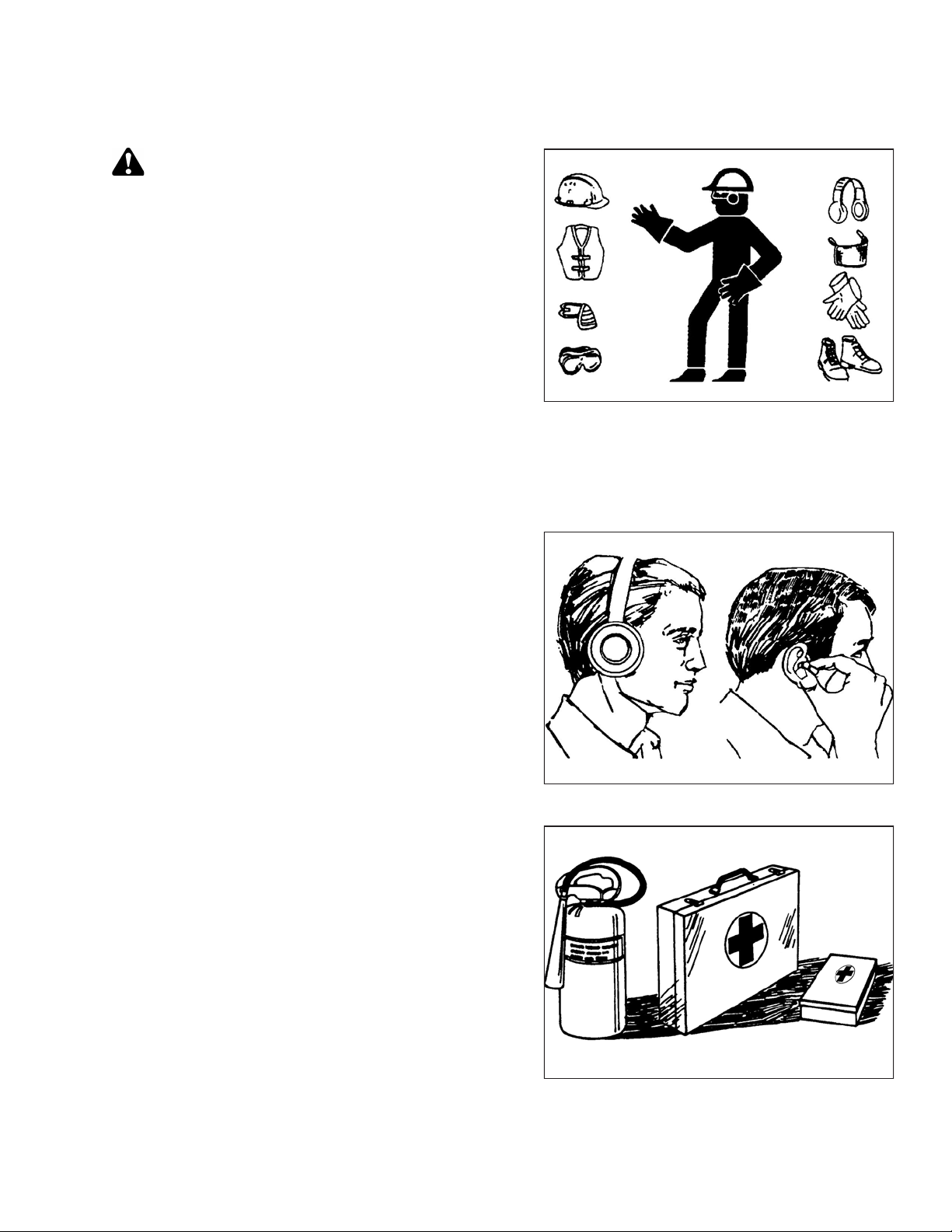
1.3 General Safety
CAUTION
The following are general farm safety precautions that
should be part of your operating procedure for all types
of machinery.
Protect yourself.
• When assembling, operating, and servicing machinery,
wear all protective clothing and personal safety devices
that could be necessary for job at hand. Do NOT take
chances. You may need the following:
• Hard hat
• Protective footwear with slip-resistant soles
• Protective glasses or goggles
• Heavy gloves
• Wet weather gear
• Respirator or filter mask
• Be aware that exposure to loud noises can cause hearing
impairment or loss. Wear suitable hearing protection
devices such as earmuffs or earplugs to help protect
against loud noises.
Figure 1.2: Safety Equipment
Figure 1.3: Safety Equipment
• Provide a first aid kit for use in case of emergencies.
• Keep a fire extinguisher on the machine. Be sure fire
extinguisher is properly maintained. Be familiar with its
proper use.
• Keep young children away from machinery at all times.
• Be aware that accidents often happen when Operator is
tired or in a hurry. Take time to consider safest way.
Never ignore warning signs of fatigue.
Figure 1.4: Safety Equipment
214683 3 Revision A
Page 28

1000007
1000008
1000009
SAFETY
• Wear close-fitting clothing and cover long hair. Never
wear dangling items such as scarves or bracelets.
• Keep all shields in place. NEVER alter or remove safety
equipment. Make sure driveline guards can rotate
independently of shaft and can telescope freely.
• Use only service and repair parts made or approved by
equipment manufacturer. Substituted parts may not meet
strength, design, or safety requirements.
• Keep hands, feet, clothing, and hair away from moving
parts. NEVER attempt to clear obstructions or objects
from a machine while engine is running.
• Do NOT modify machine. Unauthorized modifications
may impair machine function and/or safety. It may also
shorten machine’s life.
Figure 1.5: Safety around Equipment
• To avoid bodily injury or death from unexpected startup of
machine, ALWAYS stop the engine and remove the key
from the ignition before leaving the operator’s seat for
any reason.
• Keep service area clean and dry. Wet or oily floors are
slippery. Wet spots can be dangerous when working with
electrical equipment. Be sure all electrical outlets and
tools are properly grounded.
• Keep work area well lit.
• Keep machinery clean. Straw and chaff on a hot engine is
a fire hazard. Do NOTallow oil or grease to accumulate
on service platforms, ladders, or controls. Clean
machines before storage.
• NEVER use gasoline, naphtha, or any volatile material for
cleaning purposes. These materials may be toxic and/or
flammable.
• When storing machinery, cover sharp or extending
components to prevent injury from accidental contact.
Figure 1.6: Safety around Equipment
Figure 1.7: Safety around Equipment
214683 4 Revision A
Page 29

1000009
1008958
1000004
SAFETY
1.4 Maintenance Safety
To ensure your safety while maintaining machine:
• Review operator’s manual and all safety items before
operation and/or maintenance of machine.
• Place all controls in Neutral, stop the engine, set the park
brake, remove the ignition key, and wait for all moving
parts to stop before servicing, adjusting, and/or repairing.
• Follow good shop practices:
– Keep service areas clean and dry
– Be sure electrical outlets and tools are properly
grounded
– Keep work area well lit
• Relieve pressure from hydraulic circuits before servicing
and/or disconnecting machine.
• Make sure all components are tight and that steel lines,
hoses, and couplings are in good condition before
applying pressure to hydraulic systems.
Figure 1.8: Safety around Equipment
• Keep hands, feet, clothing, and hair away from all
moving and/or rotating parts.
• Clear area of bystanders, especially children, when
carrying out any maintenance, repairs, or adjustments.
• Install transport lock or place safety stands under frame
before working under machine.
• If more than one person is servicing machine at same
time, be aware that rotating a driveline or other
mechanically-driven component by hand (for example,
accessing a lubricant fitting) will cause drive components
in other areas (belts, pulleys, and knives) to move. Stay
clear of driven components at all times.
• Wear protective gear when working on machine.
• Wear heavy gloves when working on knife components.
Figure 1.9: Equipment NOT Safe for Children
Figure 1.10: Safety Equipment
214683 5 Revision A
Page 30

1001205
1001207
1000013
SAFETY
1.5 Hydraulic Safety
• Always place all hydraulic controls in Neutral before
dismounting.
• Make sure that all components in hydraulic system are
kept clean and in good condition.
• Replace any worn, cut, abraded, flattened, or crimped
hoses and steel lines.
• Do NOT attempt any makeshift repairs to hydraulic lines,
fittings, or hoses by using tapes, clamps, cements, or
welding. The hydraulic system operates under extremely
high-pressure. Makeshift repairs will fail suddenly and
create hazardous and unsafe conditions.
• Wear proper hand and eye protection when searching for
high-pressure hydraulic leaks. Use a piece of cardboard
as a backstop instead of hands to isolate and identify
a leak.
Figure 1.11: Testing for Hydraulic Leaks
• If injured by a concentrated high-pressure stream of
hydraulic fluid, seek medical attention immediately.
Serious infection or toxic reaction can develop from
hydraulic fluid piercing the skin.
• Make sure all components are tight and steel lines,
hoses, and couplings are in good condition before
applying pressure to a hydraulic system.
Figure 1.12: Hydraulic Pressure Hazard
Figure 1.13: Safety around Equipment
214683 6 Revision A
Page 31

1000694
SAFETY
1.6 Safety Signs
• Keep safety signs clean and legible at all times.
• Replace safety signs that are missing or illegible.
• If original part on which a safety sign was installed is
replaced, be sure repair part also bears current
safety sign.
• Replacement safety signs are available from your
MacDon Dealer Parts Department.
1.6.1 Installing Safety Decals
1. Clean and dry installation area.
Figure 1.14: Operator’s Manual Decal
2. Decide on exact location before you remove decal backing paper.
3. Remove smaller portion of split backing paper.
4. Place decal in position and slowly peel back remaining paper, smoothing decal as it is applied.
5. Prick small air pockets with a pin and smooth out.
214683 7 Revision A
Page 32

1.7 Safety Decal Locations
1003348
A
A
A
1003341
A
A
Figure 1.15: Upper Cross Auger
SAFETY
A - MD #174682
Figure 1.16: Slow Speed Transport
A - MD #220799
214683 8 Revision A
Page 33

Figure 1.17: Slow Speed Transport Tow-Bar
1003338
A
B
A
B
1003382
A
A
SAFETY
A - MD #220797 B - MD #220798
Figure 1.18: Vertical Knife
A - MD #174684
214683 9 Revision A
Page 34

Figure 1.19: Endsheets, Reel Arms, and Backsheet
1020695
B
A
A
C
F
F
C
E
D
E
C
A
B
E
B
C
F
D
F
SAFETY
A - MD #174632 B - MD #131393 C - MD #184422
D - MD #131392 (Double Reel Only) E - MD #131391 (Two Places) F - MD #166466 (Three Places)
214683 10 Revision A
Page 35

Figure 1.20: Backtube
1003403
A
B
C
D
E
1009678
A
BCD
C
A
E
SAFETY
A - MD #184372 B - MD #166466 C - MD #131391
D - MD #131392 E - MD #184372 (Split Frame)
214683 11 Revision A
Page 36

Figure 1.21: FM100 Float Module
1026294
A
B
A
B
SAFETY
A - MD #252996 B - MD #184372
214683 12 Revision A
Page 37

1000917
1003356
SAFETY
1.8 Understanding Safety Signs
MD #113482
General hazard pertaining to machine operation and
servicing
CAUTION
To avoid injury or death from improper or unsafe machine
operation:
• Read the operator’s manual and follow all safety
instructions. If you do not have a manual, obtain one from
your Dealer.
• Do NOT allow untrained persons to operate the machine.
• Review safety instructions with all Operators every year.
Figure 1.22: MD #113482
• Ensure that all safety signs are installed and legible.
• Make certain everyone is clear of machine before starting engine and during operation.
• Keep riders off the machine.
• Keep all shields in place and stay clear of moving parts.
• Disengage header drive, put transmission in Neutral, and wait for all movement to stop before leaving
operator’s position.
• Stop the engine and remove the key before servicing, adjusting, lubricating, cleaning, or unplugging machine.
• Engage safety props to prevent lowering of header or reel before servicing in the raised position.
• Use slow moving vehicle emblem and flashing warning lights when operating on roadways unless prohibited
by law.
MD #131391
Crushing hazard
DANGER
• Rest header on ground or engage safety props before
going under unit.
Figure 1.23: MD #131391
214683 13 Revision A
Page 38

1003404
1001649
1000706
SAFETY
MD #131392
Crushing hazard
WARNING
• To avoid injury from fall of raised reel; fully raise reel, stop
the engine, remove the key, and engage safety prop on
each reel support arm before working on or under reel.
MD #131393
Reel hazard
WARNING
• To avoid injury from fall of raised reel; fully raise reel, stop
the engine, remove the key, and engage safety prop on
each reel support arm before working on or under reel.
Figure 1.24: MD #131392
MD #166466
High-pressure oil hazard
WARNING
• Do NOT go near leaks.
• High-pressure oil easily punctures skin, causing serious
injury, gangrene, or death.
• If injured, seek emergency medical help. Immediate
surgery is required to remove oil.
• Do NOT use finger or skin to check for leaks.
• Lower load or relieve hydraulic pressure before loosening
fittings.
Figure 1.25: MD #131393
Figure 1.26: MD #166466
214683 14 Revision A
Page 39

1000920
1003402
SAFETY
MD #174436
High-pressure oil hazard
WARNING
• Do not go near leaks.
• High-pressure oil easily punctures skin, causing serious
injury, gangrene, or death.
• If injured, seek emergency medical help. Immediate
surgery is required to remove oil.
• Do not use finger or skin to check for leaks.
• Lower load or relieve hydraulic pressure before loosening
fittings.
MD #174632
Reel entanglement hazard
CAUTION
• To avoid injury from entanglement with rotating reel,
stand clear of header while machine is running.
Figure 1.27: MD #174436
Figure 1.28: MD #174632
MD #184372
General hazard pertaining to machine operation and
servicing
CAUTION
To avoid injury or death from improper or unsafe machine
operation:
• Read the operator’s manual and follow all safety
instructions. If you do not have a manual, obtain one from
your Dealer.
• Do NOT allow untrained persons to operate the machine.
• Review safety instructions with all Operators annually.
Figure 1.29: MD #184372
• Ensure that all safety signs are installed and legible.
• Make certain everyone is clear of machine before starting engine and during operation.
• Keep riders off the machine.
• Keep all shields in place and stay clear of moving parts.
214683 15 Revision A
Page 40

1000923
1003333
SAFETY
• Disengage header drive, put transmission in Neutral, and wait for all movement to stop before leaving
operator’s position.
• Stop the engine and remove the key from the ignition before servicing, adjusting, lubricating, cleaning, or
unplugging machine.
• Engage safety props to prevent lowering of raised unit before servicing in the raised position.
• Use slow moving vehicle emblem and flashing warning lights when operating on roadways unless prohibited
by law.
MD #184422
Chain drive hand and arm entanglement hazard
WARNING
• Do NOT open or remove safety shields while engine is
running.
• To avoid injury, stop the engine and remove the key
before opening shield.
MD #220797
Tipping hazard in transport mode
WARNING
• Read the operator’s manual for more information on
potential tipping or rollover of header while transporting.
Figure 1.30: MD #184422
Figure 1.31: MD #220797
214683 16 Revision A
Page 41

1003337
1003331
1026259
SAFETY
MD #220798
Loss of control hazard in transport
CAUTION
• Do not tow the header with a dented or otherwise
damaged tow pole (the circle with the red X shows a dent
in the pole).
• Consult the operator’s manual for more information.
MD #220799
Transport/roading hazard
WARNING
• Ensure tow-bar lock mechanism is locked.
Figure 1.32: MD #220798
MD #252996
Hot oil spray hazard
WARNING
• Hydraulic oil is under pressure and may be hot.
• Never remove fill cap when machine is hot. Always allow
machine to cool down before removing fill cap.
Figure 1.33: MD #220799
Figure 1.34: MD #252996
214683 17 Revision A
Page 42

1019658
SAFETY
MD #279085
Auger entanglement hazard
WARNING
• To avoid injury from rotating auger, stand clear of auger
while machine is running.
Figure 1.35: MD #279085
214683 18 Revision A
Page 43

2 Product Overview
2.1 Definitions
The following terms and acronyms may be used in this manual:
Term
AHHC Automatic Header Height Control
API American Petroleum Institute
ASTM American Society of Testing and Materials
Bolt
Center-link
CGVW Combined gross vehicle weight
D1 Series header
DDD Double-draper drive
DK
DKD
DR Double reel
FD1 Series header
FFFT
Finger tight
Definition
A headed and externally threaded fastener that is designed to be paired with a nut
A hydraulic cylinder link between header and machine used to change header angle
MacDon D120, D125, D130, D135, D140, and D145 combine draper header from
D1 model number series
Double knife
Double-knife drive
MacDon FD130, FD135, FD140, or FD145 combine FlexDraper
FD1 Series model number series
Flats from finger tight
Finger tight is a reference position where sealing surfaces or components are
making contact with each other, and fitting has been tightened to a point where
fitting is no longer loose
®
header from the
GVW Gross vehicle weight
Hard joint
Header
Hex key
HDS Hydraulic deck shift
hp Horsepower
JIC
Knife A cutting device which uses a reciprocating cutter (also called a sickle)
MDS Mechanical deck shift
n/a
214683 19 Revision A
A joint made with use of a fastener where joining materials are highly
incompressible
A machine that cuts crop and feeds it into an attached combine
A tool of hexagonal cross-section used to drive bolts and screws that have a
hexagonal socket in head (internal-wrenching hexagon drive); also known as an
Allen key and various other synonyms
Joint Industrial Council: A standards body that developed standard sizing and shape
for original 37° flared fitting
Not applicable
Page 44

PRODUCT OVERVIEW
Term
NPT
Nut
ORB
ORFS
RoHS (Reduction of
Hazardous Substances)
rpm
Definition
National Pipe Thread: A style of fitting used for low-pressure port openings. Threads
on NPT fittings are uniquely tapered for an interference fit
An internally threaded fastener that is designed to be paired with a bolt
O-ring boss: A style of fitting commonly used in port openings on manifolds, pumps,
and motors
O-ring face seal: A style of fitting commonly used for connecting hoses and tubes.
This style of fitting is also commonly called ORS, which stands for O-ring seal
A directive by the European Union to restrict use of certain hazardous substances
(such as hexavalent chromium used in some yellow zinc platings)
Revolutions per minute
SAE Society of Automotive Engineers
Screw
A headed and externally threaded fastener that threads into preformed threads or
forms its own thread into a mating part
SDD Single-draper drive
Soft joint
spm
A joint made with use of a fastener where joining materials are compressible or
experience relaxation over a period of time
Strokes per minute
Tension
TFFT
Torque
Torque angle
Torque-tension
Truck
UCA
Untimed knife drive
Washer
Axial load placed on a bolt or screw, usually measured in Newtons (N) or
pounds (lb.)
Turns from finger tight
The product of a force X lever arm length, usually measured in Newton-meters (Nm)
or foot-pounds (lbf∙ft)
A tightening procedure where fitting is assembled to a precondition (finger tight) and
then nut is turned farther a number of degrees to achieve its final position
The relationship between assembly torque applied to a piece of hardware and axial
load it induces in bolt or screw
A four-wheel highway/road vehicle weighing no less than 3400 kg (7500 lb.)
Upper cross auger
Unsynchronized motion applied at cutterbar to two separately driven knives from a
single hydraulic motor or two hydraulic motors
A thin cylinder with a hole or slot located in the center that is to be used as a spacer,
load distribution element, or locking mechanism
214683 20 Revision A
Page 45

PRODUCT OVERVIEW
2.2 Specifications
The following symbol and letters are used in Table 2.1, page 21 and Table 2.2, page 23:
| FD1 | FM100 | Attachments
S: standard / O
: optional (factory installed) / OD: optional (dealer installed) / –: not available
F
Table 2.1 Header Specifications
Cutterbar
Effective cutting width (distance between crop divider points)
9.1 m (30 ft.) header 914.4 cm (360 in.) S
10.7 m (35 ft.) header 10.668 m (420 in.) S
12.2 m (40 ft.) header 12.192 m (480 in.) S
13.7 m (45 ft.) header 13.716 m (540 in.) S
Cutterbar lift range
Varies with combine model
Knife
Single-knife drive (all sizes): hydraulic motor to C-belt to enclosed heavy-duty (MD) knife drive box.
Double knife drive (12.2 and 13.7 m [40 and 45 ft.]): two hydraulic motors to C-belts, untimed, to enclosed
heavy-duty (MD) knife drive boxes.
Knife stroke 76 mm (3 in.) S
Single-knife speed (strokes per minute)
Single-knife speed (strokes per minute)
Single-knife speed (strokes per minute)
1
1
1
9.1 m (30 ft.)
10.7 m (35 ft.)
12.2 m (40 ft.)
1200–1400 spm
1100–1300 spm
1050–1200 spm
S
O
F
O
F
S
S
S
Double-knife speed (strokes per minute)
1
12.2, 13.7 m (40, 45 ft.)
1100–1400 spm
Knife Sections
Over-serrated / solid / bolted / 3.5 serrations per cm (9 serrations per inch) S
Knife overlap at center (double-knife headers) 3 mm (1/8 in.) S
Guards and Hold-Downs
Guard: pointed / forged / double heat treated (DHT)
Hold-down: sheet metal / adjustment bolt
Guard Angle (Cutterbar on Ground)
Center-link retracted
Center-link extended
2.0 degrees
7.4 degrees
Draper (Conveyor) and Decks
Draper width
1.057 m (41-19/32 in.) S
Draper drive Hydraulic
1. Under normal cutting conditions, knife speed taken at the knife drive pulley should be set at 600 rpm
(1200 spm). If set to low end of the speed range, you could experience knife stalling.
S
S
S
S
S
214683 21 Revision A
Page 46

PRODUCT OVERVIEW
Table 2.1 Header Specifications (continued)
Draper speed: FM100 Float Module controlled
0–193 m/min. (635 fpm) S
PR15 Pick-Up Reel
Quantity of tine tubes
5-, 6-, or 9-tine tubes
Center tube diameter 203 mm (8 in.) S
Finger tip radius Factory-set
Finger tip radius Adjustment range
800 mm (31-1/2 in.) S
766–800 mm
(30-3/16–31-1/2 in.)
Effective reel diameter (via cam profile) 1.650 m (65 in.) S
Finger length
290 mm (11 in.) S
Finger spacing (staggered on alternate bats) 150 mm (6 in.) S
Reel drive Hydraulic
Reel speed (adjustable from cab, varies with combine model)
0–67 rpm
Frame and Structure
Header
width
Header
width
Field mode
Transport position - reel
fore-aft fully retracted
(shortest center-link)
(A) Long dividers installed
(refer to Figure 2.1, page 23)
Cut width +
384 mm (15-1/8 in.)
2.684 m (106 in.)
—
S
S
S
S
Header
width
Transport position - reel
fore-aft fully retracted
(shortest center-link)
(B) Long dividers removed
(refer to Figure 2.1, page 23)
2.500 m (98 in.)
—
214683 22 Revision A
Page 47

Figure 2.1: Header Dimensions
1025198
A
B
C
PRODUCT OVERVIEW
Table 2.2 Header Attachments
FM100 Float Module
Feed draper Width
Feed draper
Speed
Feed auger Width
Feed auger
Outside diameter 559 mm (22 in.) S
Feed auger Tube diameter
Feed auger
Speed (varies with combine model)
Oil reservoir capacity
Oil type
Driveline overall length
Driveline overall length
2
2
Case, New Holland
Case, New Holland
Maximum
(extended)
Minimum
(compressed)
2.000 m
(78-11/16 in.)
107–122 m/min
(350–400 fpm)
1.660 m
(65-5/16 in.)
356 mm (14 in.) S
190 rpm
75 liters
(20 US gallons)
DURATRAN
™
1.230 m (48-7/16 in.) O
603 mm
(23-3/4 in.)
O
S
S
S
S
S
—
F
F
2. Subtract 265 mm (10-7/16 in.) for length between yoke pins.
214683 23 Revision A
Page 48

Table 2.2 Header Attachments (continued)
PRODUCT OVERVIEW
Driveline overall length
2
John Deere, CLAAS,
Massey Ferguson
Challenger, Gleaner,
Challenger, Gleaner,
Driveline overall length
2
John Deere, CLAAS,
Massey Ferguson
Driveline overall length
Driveline overall length
2
2
John Deere 9650/9660
John Deere 9650/9660
Upper Cross Auger O
Outside diameter 305 mm (12 in.)
Tube diameter
Stabilizer Wheel / Slow Speed Transport O
Wheels 15 in.
Tires
Maximum
(extended)
Minimum
(compressed)
Maximum
(extended)
Minimum
(compressed)
1.262 m
(49-11/16 in.)
916 mm
(36-1/16 in.)
775 mm (30-1/2 in.) O
880 mm (34-5/8 in.) O
152 mm (6 in.)
P205/75 R-15
O
O
F
F
F
F
D
—
—
D
—
—
Weight
Estimated weight range – base header, no float module – variances are due to different package configurations.
9.1 m (30 ft.) header
10.7 m (35 ft.) header
12.2 m (40 ft.) header
North America frame
12.2 m (40 ft.) header Export frame
13.7 m (45 ft.) header
North America frame
13.7 m (45 ft.) header Export frame
2218–2317 kg (4890–5240 lb.)
2409–2558 kg (5310–5640 lb.)
2644–2708 kg (5830–5970 lb.)
2685–2706 kg (5920–5965 lb.)
2903 kg (6400 lb.)
2892–2912 kg (6375–6420 lb.)
214683 24 Revision A
Page 49

1017159
A
B
C
D
E
F
G
H
K
L
J
M
PRODUCT OVERVIEW
2.3 Component Identification
2.3.1 FD1 Series FlexDraper
®®
Figure 2.2: FD1 Series FlexDraper®®Components
A - Wing Float Linkage B - Center Reel Arm C - Reel Fore-Aft Cylinder
D - Endshield E - Reel Lift Cylinder F - Knife Drive Box (inside endshield)
G - Side Draper H - Center Reel Drive J - Pick-up Reel
K - Reel Endshield L - Crop Divider M - Header Light (except Europe)
214683 25 Revision A
Page 50

1012484
A
B
C
D
E
F
F
B
G
H
PRODUCT OVERVIEW
2.3.2 FM100 Float Module
Figure 2.3: Header Side of FM100 Float Module
A - Feed Auger B - Header Float Springs C - Center-Link
D - Hydraulic Reservoir E - Gearbox F - Header Support Arms
G - Feed Draper H - Hydraulic Filter
214683 26 Revision A
Page 51

1016972
A
B
C
D
E
F
G
H
H
J
G
PRODUCT OVERVIEW
Figure 2.4: Combine Side of FM100 Float Module
A - Float Module Gearbox B - Hydraulic Compartment Cover C - Reservoir Oil Level Sight Glass
D - Center-Link E - Header Height Control Indicator F - Torque Wrench
G - Drain Tube (x2) H - Float Lock Handle (x2) J - Auto Header Height Control (AHHC) Sensor
214683 27 Revision A
Page 52

Page 53

3 Operation
3.1 Owner/Operator Responsibilities
CAUTION
• It is your responsibility to read and understand this manual completely before operating the header.
Contact your MacDon Dealer if an instruction is not clear to you.
• Follow all safety messages in the manual and on safety decals on the machine.
• Remember that YOU are the key to safety. Good safety practices protect you and the people
around you.
• Before allowing anyone to operate the header, for however short a time or distance, make sure they
have been instructed in its safe and proper use.
• Review the manual and all safety related items with all Operators annually.
• Be alert for other Operators not using recommended procedures or not following safety precautions.
Correct these mistakes immediately, before an accident occurs.
• Do NOT modify the machine. Unauthorized modifications may impair the function and/or safety of the
machine and may reduce the length of service you receive from your machine.
• The safety information given in this manual does not replace safety codes, insurance needs, or laws
governing your area. Be sure your machine meets the standards set by these regulations.
214683 29 Revision A
Page 54

1001602
1001683
OPERATION
3.2 Operational Safety
CAUTION
Adhere to the following safety precautions:
• Follow all safety and operational instructions
provided in your operator’s manuals. If you do not
have a combine manual, get one from your Dealer and
read it thoroughly.
• Never attempt to start the engine or operate the
machine except from the combine seat.
• Check the operation of all controls in a safe, clear
area before starting work.
• Do NOT allow riders on the combine.
CAUTION
• Never start or move the machine until you are sure all
bystanders have cleared the area.
Figure 3.1: No Riders
• Avoid travelling over loose fill, rocks, ditches,
or holes.
• Drive slowly through gates and doorways.
• When working on inclines, travel uphill or downhill
whenever possible. Be sure to keep transmission in
gear when travelling downhill.
• Never attempt to get on or off a moving machine.
• Do NOT leave operator’s station while the engine is
running.
• To avoid bodily injury or death from unexpected startup of a machine, always stop the engine and
remove the key before adjusting or removing plugged material from the machine.
• Check for excessive vibration and unusual noises. If there is any indication of trouble, shut down and
inspect the machine. Follow proper shutdown procedure. Refer to 3.4 Shutting down the Combine,
page 41.
• Operate only in daylight or good artificial light.
Figure 3.2: Bystander Safety
3.2.1 Header Safety Props
The header safety props, located on the header lift cylinders, prevent the lift cylinders from unexpectedly retracting
and lowering the header. Refer to your combine operator’s manual for instructions.
DANGER
To avoid bodily injury or death from unexpected start-up or fall of raised machine, always stop engine,
remove key, and engage safety props before going under header for any reason.
214683 30 Revision A
Page 55

1001694
A
B
OPERATION
3.2.2 Reel Safety Props
The reel safety props, located on the reel support arms, prevent the reel from unexpectedly lowering.
WARNING
To avoid bodily injury from fall of raised reel, always engage reel safety props before going under raised
reel for any reason.
IMPORTANT:
To prevent damage to the reel support arms, do NOT transport the header with the reel safety props engaged.
Engaging Reel Safety Props
1. Raise reel to maximum height.
2. Move reel safety props (A) to engaged position
(as shown).
NOTE:
Keep pivot bolt (B) sufficiently tight so prop remains in
stored position when not in use, but can be engaged
using hand force.
3. Repeat on right reel arm.
Figure 3.3: Reel Safety Prop – Left Side
214683 31 Revision A
Page 56

1001695
A
C
B
1004154
A
OPERATION
4. Use handle (A) to move lock rod to inboard position (B),
which engages pin (C) under prop.
5. Lower reel until safety props contact the outer arm
cylinder mounts and the center arm pins.
Disengaging Reel Safety Props
1. Raise the reel to maximum height.
2. Move the reel safety props (A) back inside the
reel arms.
Figure 3.4: Reel Safety Prop – Center Arm
Figure 3.5: Reel Safety Prop – Left Side Shown
(Right Opposite)
214683 32 Revision A
Page 57

1001697
B
A
1024277
A
B
1024681
A
B
C
OPERATION
3. Use handle (B) to move lock rod (A) to the
outboard position.
Figure 3.6: Reel Safety Prop – Center Arm
3.2.3 Endshields
A hinged, polyethylene endshield is fitted on each end of the header.
Opening Endshields
1. Push release lever (A) located on the backside of the
endshield to unlock the shield.
2. Pull endshield open using handle depression (B).
3. Pull endshield at handle depression (A). Endshield is
retained by a hinge tab (B) and will open in
direction (C).
Figure 3.7: Left Endshield
214683 33 Revision A
Figure 3.8: Left Endshield
Page 58

1012300
A
B
1012300
A
B
1024683
A
OPERATION
4. If additional clearance is required, pull the endshield
free of hinge tab (A) and swing shield towards the rear
of the header.
5. Engage safety latch (B) on hinge arm to secure the
shield in fully open position.
Closing Endshields
1. Disengage lock (B) to allow endshield to move.
2. Insert front of endshield behind hinge tab (A) and into
divider cone.
Figure 3.9: Left Endshield
3. Swing endshield in direction (A) into closed position.
Engage lock with a firm push.
4. Check that endshield is locked.
Figure 3.10: Left Endshield
Figure 3.11: Left Endshield
214683 34 Revision A
Page 59

1001672
X
1025332
A
B
A
A
A
OPERATION
Checking and Adjusting Endshields
Endshields are subject to expansion or contraction caused by large temperature variations. The position of the top
pin and lower latch can be adjusted to compensate for dimensional changes.
Checking the endshield:
1. Check gap (X) between front end of shields and header
frame and compare to the values in Table 3.1, page 35.
Table 3.1 Endshield Gap at Various Temperatures
Temperature in °C (°F)
Gap (X)
mm (in.)
7 (45) 13–18 (1/2–23/32)
18 (65) 10–15 (3/8–19/32)
29 (85) 7–12 (9/32–15/32)
41 (105) 4–9 (5/32–11/32)
Adjusting the endshield gap:
1. Loosen the four bolts (A) on support tube bracket (B).
Figure 3.12: Gap between Endshield and
Header Frame
Figure 3.13: Left Endshield Support Tube
214683 35 Revision A
Page 60

1024666
A
B
1025332
A
B
A
A
A
1025329
C
A
B
C
OPERATION
2. Loosen the three bolts (A) on latch assembly (B).
3. Adjust latch assembly (B) to achieve the desired gap
between the front end of the shield and the header
frame. Refer to Table 3.1, page 35 for the
recommended endshield gap at various temperatures.
4. Tighten the three bolts (A) on the latch assembly.
5. Tighten the four bolts (A) on support tube bracket (B).
6. Close endshield.
Figure 3.14: Left Endshield Latch Assembly
Removing Endshields
1. Fully open the endshield. For instructions, refer to
Opening Endshields, page 33.
2. Engage lock (A) to prevent endshield movement.
3. Remove self-tapping screw (B).
4. Slide endshield upwards and remove from hinge
arm (C).
5. Place endshield away from work area.
Figure 3.15: Left Endshield Support Tube
Figure 3.16: Left Endshield
214683 36 Revision A
Page 61

1025329
C
A
B
C
1004527
A
B
OPERATION
Installing Endshields
1. Guide endshield onto hinge arm (C) and slowly slide it
downwards.
NOTE:
Ensure hinge arm (C) is installed in the outboard hole
on the hinge bracket, as shown in illustration at right.
2. Install self-tapping screw (B).
3. Disengage lock (A) to allow endshield movement.
4. Close endshield. Refer to Closing Endshields, page 34.
NOTE:
Endshields may expand or contract when subjected to
large temperature changes. Top pin and lower latch
bracket positions can be adjusted to compensate for
dimensional changes. Refer to Checking and Adjusting
Endshields, page 35.
3.2.4 Linkage Covers
Figure 3.17: Left Endshield
Plastic covers are attached to the header frame to protect the header wing balance mechanism from debris and
weather.
Removing Linkage Covers
1. Remove screw (A) and lift outboard end of cover (B).
Figure 3.18: Linkage Cover
214683 37 Revision A
Page 62

1004528
A
1004530
A
B
1004527
A
B
OPERATION
2. Rotate cover (A) upward until inboard end can be
lifted off.
Installing Linkage Covers
1. Position inboard end of cover (A) over linkage and
behind indicator bar (B).
2. Lower cover until secure and against header tube.
Figure 3.19: Linkage Cover
3. Install screw (A) to hold cover (B) in place.
Figure 3.20: Linkage Cover
Figure 3.21: Linkage Cover
214683 38 Revision A
Page 63

1001351
OPERATION
3.2.5 Daily Start-Up Check
CAUTION
• Clear the area of other persons, pets, etc. Keep
children away from machinery. Walk around the
machine to be sure no one is under, on, or close to it.
• Wear close-fitting clothing and protective shoes with
slip-resistant soles.
• Remove foreign objects from the machine and
surrounding area.
• Carry with you any protective clothing and personal
safety devices that could be necessary through the
day. Do NOT take chances. You may need a hard hat,
protective glasses or goggles, heavy gloves, a
respirator or filter mask, or wet weather gear.
• Protect against noise. Wear a suitable hearing protective device such as ear muffs or ear plugs to
protect against objectionable or uncomfortably loud noises.
Complete the following tasks each day before start-up:
Figure 3.22: Safety Devices
1. Check the machine for leaks and any parts that are missing, broken, or not working correctly.
NOTE:
Use proper procedure when searching for pressurized fluid leaks. Refer to 5.3.5 Checking Hydraulic Hoses and
Lines, page 390.
2. Clean all lights and reflective surfaces on the machine.
3. Perform all daily maintenance. Refer to 5.3.1 Maintenance Schedule/Record, page 385.
214683 39 Revision A
Page 64

OPERATION
3.3 Break-in Period
CAUTION
Before investigating an unusual sound or attempting to correct a problem, shut off engine and
remove key.
NOTE:
Until you become familiar with the sound and feel of your new header, be extra alert and attentive.
After attaching the header to the combine for the first time, follow these steps:
1. Operate the machine with the reels, drapers, and knives running slowly for five minutes. Watch and listen
FROM THE OPERATOR’S SEAT for binding or interfering parts.
NOTE:
Reels and side drapers will not operate until oil flow fills the lines.
2. Refer to 5.3.2 Break-In Inspection, page 388 and perform all the specified tasks.
214683 40 Revision A
Page 65

OPERATION
3.4 Shutting down the Combine
DANGER
To avoid bodily injury or death from unexpected start-up of machine, always stop engine and remove key
from ignition before leaving operator’s seat for any reason.
To shut down the combine and before leaving the operator’s seat for any reason, follow these steps:
1. Park on level ground whenever possible.
2. Lower the header fully.
3. Place all controls in NEUTRAL or PARK.
4. Disengage the header drive.
5. Lower and fully retract the reel.
6. Stop the engine and remove the key from the ignition.
7. Wait for all movement to stop.
214683 41 Revision A
Page 66

OPERATION
3.5 Cab Controls
CAUTION
Be sure all bystanders are clear of machine before starting engine or engaging any header drives.
Refer to your combine operator’s manual for identification of the following in-cab controls:
• Header engage/disengage control
• Header height
• Header angle
• Ground speed
• Reel speed
• Reel height
• Reel fore-aft position
214683 42 Revision A
Page 67

OPERATION
3.6 Header Setup
3.6.1 Header Attachments
Several attachments to improve the performance of your header are available as options that can be installed by
your MacDon Dealer. Refer to 6 Options and Attachments, page 545 for descriptions of available items.
3.6.2 Header Settings
The following tables provide a guideline for setting up the FD1 FlexDraper®Header; however, the suggested
settings can be changed to suit various crops and conditions not covered in the tables.
Refer also to 3.6.4 Reel Settings, page 56.
For FM100 auger configurations, refer to 4.1 Float Module Feed Auger Configurations, page 307.
214683 43 Revision A
Page 68

Auger
Upper Cross
Recommended
Auger
Upper Cross
Not required
Reel Position
7
Reel
Speed %
Reel Cam
56
Header
Angle
4
2 10 6 or 7 Not required
310–15 6 or 7 Not required
B – C
B – C
3or4 5–10 4 or 5 Not required
B – C
B – C2 106or7
Reel Position
7
Reel
Speed %
Reel Cam
56
Header
Angle
4
10–15 6 or 7
4
A 2 10 6 or 7 Not required
A 2 10 6 or 7 Recommended
D3or45–10 4 or 5 Not required
8
Setting
Draper Speed
Off
On
Up or middle
Crop
Position
Divider Rods
Light
Condition
Normal
Storage
3
Stubble Height 102 (<4)
Stabilizer
Wheels
Table 3.2 Recommended FD1 Series / FM100 Combine Header Settings for Cereals
214683 44 Revision A
Skid Shoe
Off
On
Heavy
Lodged
Stubble Height 102–203 (4–8)
Stabilizer
As required
Wheels
Skid Shoe
Down for lodged crop conditions, middle or down for other crop conditions
Position
Setting
Draper Speed
Divider Rods
Crop
Condition
8B– C
Off
Light
7
7
On
On
Heavy
Normal
7
Off
Lodged
Stubble Height 203+ (8+)
As required
Stabilizer
Wheels
3. Stabilizer wheels are used to limit the side-to-side movement when cutting off the ground in rolling terrain and to minimize bouncing.
4. Setting on FM100 draper control.
5. Set header angle as shallow as possible (setting A) with center-link and skid shoes while maintaining cutting height.
6. Cutting height is controlled with a combination of skid shoes and header angle.
7
7
7
7. Percentage above ground speed.
Page 69

Auger
Upper Cross
Reel Position
7
Not required
OPERATION
Not required
Reel
Speed %
Reel Cam
56
Header
Angle
4
Setting
Draper Speed
10–15 6 or 7
3or4 5–10 4 or 5 Not required
A4
8
A 2 10 6 or 7 Not required
7
B – C
B – C2 106or7
7
7
Off
On
Divider Rods
Not applicable
Crop
Skid Shoe
Table 3.2 Recommended FD1 Series / FM100 Combine Header Settings for Cereals (continued)
214683 45 Revision A
Position
Light
Condition
Normal
Off
On
Heavy
Lodged
Page 70

Auger
Upper Cross
Reel Position
12
Reel
Speed %
Reel Cam
2 10 6 or 7 Not required
25–10 6 or 7 Not required
2 10 6 or 7 Not required
Stubble Height On ground
Table 3.3 Recommended FD1 Series / FM100 Combine Header Settings for Lentils
Storage
Up or middle
8
Stabilizer
Wheels
Skid Shoe
10 11
Header
Angle
9
Setting
Draper Speed
Divider Rods
Crop
Condition
Position
B – C
8
On
Light
B – C
B – C
7
7
On
On
Heavy
Normal
D25–10 6 or 7 Not required
7
On
Lodged
8. Stabilizer wheels are used to limit the side-to-side movement when cutting off the ground in rolling terrain and to minimize bouncing.
9. Setting on FM100 draper control.
10. Set header angle as shallow as possible (setting A) with center-link and skid shoes while maintaining cutting height.
11. Cutting height is controlled with a combination of skid shoes and header angle.
12. Percentage above ground speed.
214683 46 Revision A
Page 71

Auger
Upper Cross
Reel Position
17
Reel
Speed %
Reel Cam
4 or 5 Recommended
2 10 4 or 5 Recommended
2 10 6 or 7 Recommended
25–10 6 or 7 Recommended
25–10
Table 3.4 Recommended FD1 Series / FM100 Combine Header Settings for Peas
Stubble Height On ground
Stabilizer
Storage
13
Wheels
Skid Shoe
Header
Draper Speed
Up or middle
Crop
Position
15 16
B – C
Angle
14
7
Setting
On
Divider Rods
Light
Condition
B – C
B – C
7
7
On
On
Heavy
Normal
7D
On
Lodged
13. Stabilizer wheels are used to limit the side-to-side movement when cutting off the ground in rolling terrain and to minimize bouncing.
14. Setting on FM100 draper control.
15. Set header angle as shallow as possible (setting A) with center-link and skid shoes while maintaining cutting height.
16. Cutting height is controlled with a combination of skid shoes and header angle.
17. Percentage above ground speed.
214683 47 Revision A
Page 72

Auger
Upper Cross
Recommended
Auger
Upper Cross
Reel Position
22
Reel
Speed %
Reel Cam
20 21
Header
Angle
19
1 10 3 or 4 Recommended
1 10 6 or 7 Recommended
A25–10 6 or 7 Recommended
B – C
7
7
25–10 3 or 4
D
B – C
8
7
Reel Position
Reel
Speed %
Reel Cam
20 21
Header
Angle
19
2 10 6 or 7 Recommended
1 or 2 10 3 or 4 Recommended
A25–10 6 or 7 Recommended
B – C
7
7
D2or35–10 3 or 4 Recommended
B – C
8
7
Setting
Draper Speed
On
On
On
As required
18
Stubble Height 102–203 (4–8)
Stabilizer
Wheels
Table 3.5 Recommended FD1 Series / FM100 Combine Header Settings for Canola
214683 48 Revision A
Skid Shoe
Divider Rods
Down for light or heavy crop conditions, middle or down for normal or lodged crop conditions
Crop
Condition
Position
Light
Normal
On
Heavy
Lodged
Stubble Height 203+ (8+)
Stabilizer
As required
Not applicable
Wheels
Skid Shoe
Setting
Draper Speed
Divider Rods
Crop
Condition
Position
On
Light
On
On
Heavy
Normal
On
Lodged
18. Stabilizer wheels are used to limit the side-to-side movement when cutting off the ground in rolling terrain and to minimize bouncing.
19. Setting on FM100 draper control.
20. Set header angle as shallow as possible (setting A) with center-link and skid shoes while maintaining cutting height.
21. Cutting height is controlled with a combination of skid shoes and header angle.
22. Percentage above ground speed.
Page 73

Auger
Upper Cross
4 or 5 Not required
Auger
Upper Cross
Not required
Reel Position
28
Reel
Speed %
Reel Cam
26 27
Header
Angle
25
2 10 4 or 5 Not required
B – C2 10
B – C
Reel Position
28
Reel
Speed %
Reel Cam
26 27
Header
Angle
25
310–15 6 or 7
3 10 6 or 7 Not required
3 10 6 or 7 Not required
B – C
B – C
Setting
Draper Speed
24
Up or middle
Crop
Position
Divider Rods
Light Rice divider rod 4 D 2 10–15 6 or 7 Not required
Condition
As required
Middle or down
23
Heavy Rice divider rod 4
Normal Rice divider rod 4
Lodged Rice divider rod 4 D 2 5–10 4 or 5 Not required
Stubble Height 102–203 (4–8)
Stabilizer
Wheels
Skid Shoe
Storage
23
Stubble Height 102 (<4)
Stabilizer
Wheels
Table 3.6 Recommended FD1 Series / FM100 Combine Header Settings for California Rice
214683 49 Revision A
Skid Shoe
Setting
Draper Speed
24
Divider Rods
Crop
Condition
Position
Light Rice divider rod 4 D
Heavy Rice divider rod 4
Normal Rice divider rod 4
Lodged Rice divider rod 4 D 4 5–10 6 or 7 Not required
23. Stabilizer wheels are used to limit the side-to-side movement when cutting off the ground in rolling terrain and to minimize bouncing.
24. The rice divider rod is available. Rice divider rod not required on both ends of header.
25. Setting on FM100 draper control.
26. Set header angle as shallow as possible (setting A) with center-link and skid shoes while maintaining cutting height.
27. Cutting height is controlled with a combination of skid shoes and header angle.
28. Percentage above ground speed.
Page 74

Auger
Upper Cross
Reel Position
28
Reel
Speed %
OPERATION
Not required
As required
Reel Cam
26 27
Header
Angle
25
Setting
Draper Speed
24
Divider Rods
Not applicable
3 10 6 or 7 Not required
B – C3 106or7
B – C
23
Crop
Stubble Height 203+ (8+)
Stabilizer
Wheels
Skid Shoe
Table 3.6 Recommended FD1 Series / FM100 Combine Header Settings for California Rice (continued)
214683 50 Revision A
Position
Light Rice divider rod 4 A 3 10–15 6 or 7 Not required
Condition
Normal Rice divider rod 4
Heavy Rice divider rod 4
Lodged Rice divider rod 4 D 4 5–10 6 or 7 Not required
Page 75

Auger
Upper Cross
Not required
Auger
Upper Cross
Not required
Reel Position
33
Reel
Speed %
Reel Cam
31 32
Header
Angle
30
2 or 3 10 6 or 7 Not required
B – C
6
6D2or310–15 6 or 7 Not required
6B– C 2 or 3 10 6 or 7
6D3or45–10 4 or 5 Not required
Reel Position
33
Reel
Speed %
Reel Cam
31 32
Header
Angle
30
2or3 10–15 6 or 7
A
6
2 or 3 10 6 or 7 Not required
2 or 3 10 6 or 7 Not required
B – C
B – C
6
6
6D3or45–10 4 or 5 Not required
Setting
Draper Speed
Off
Off
Off
Middle or down
Crop
Position
Divider Rods
Light
Condition
Normal
As required
29
Stabilizer
Wheels
Stubble Height 51–152 (2–6)
Table 3.7 Recommended FD1 Series / FM100 Combine Header Settings for Delta Rice
214683 51 Revision A
Skid Shoe
Off
Heavy
Lodged
Stubble Height 152+ (6+)
Stabilizer
As required
Not applicable
Wheels
Skid Shoe
Setting
Draper Speed
Divider Rods
Crop
Condition
Position
Off
Light
Off
Off
Heavy
Normal
Off
Lodged
29. Stabilizer wheels are used to limit the side-to-side movement when cutting off the ground in rolling terrain and to minimize bouncing.
30. Setting on FM100 draper control.
31. Set header angle as shallow as possible (setting A) with center-link and skid shoes while maintaining cutting height.
32. Cutting height is controlled with a combination of skid shoes and header angle.
33. Percentage above ground speed.
Page 76

Auger
Upper Cross
Reel Position
38
Reel
Speed %
Reel Cam
2 10 6 or 7 Not required
2 10 6 or 7 Not required
Stubble Height On ground
Table 3.8 Recommended FD1 Series / FM100 Combine Header Settings for Edible Beans
Storage
Up or middle
34
Stabilizer
Wheels
Skid Shoe
36 37
Header
Angle
35
Setting
Draper Speed
Divider Rods
Crop
Condition
Position
B – C
8D25–10 6 or 7 Not required
7
On
On
Light
Normal
D25–10 6 or 7 Not required
B – C
7
7
On
On
Heavy
Lodged
34. Stabilizer wheels are used to limit the side-to-side movement when cutting off the ground in rolling terrain and to minimize bouncing.
35. Setting on FM100 draper control.
36. Set header angle as shallow as possible (setting A) with center-link and skid shoes while maintaining cutting height.
37. Cutting height is controlled with a combination of skid shoes and header angle.
38. Percentage above ground speed.
214683 52 Revision A
Page 77

Auger
Upper Cross
Reel Position
43
Reel
Speed %
Reel Cam
Not required
25–10 6 or 7 Not required
Table 3.9 Recommended FD1 Series / FM100 Combine Header Settings for Flax
Stabilizer
Stubble Height 51–153 (2–6)
As required
39
Wheels
Skid Shoe
41 42
Header
Angle
40
Setting
Draper Speed
Divider Rods
Down for lodged crop conditions, middle or down for other crop conditions
Crop
Condition
Position
B – C
8
On
Light
A 2 10 6 or 7 Not required
D25–10 6 or 7 Not required
B – C2 106or7
7
7
7
On
On
On
Heavy
Normal
Lodged
39. Stabilizer wheels are used to limit the side-to-side movement when cutting off the ground in rolling terrain and to minimize bouncing.
40. Setting on FM100 draper control.
41. Set header angle as shallow as possible (setting A) with center-link and skid shoes while maintaining cutting height.
42. Cutting height is controlled with a combination of skid shoes and header angle.
43. Percentage above ground speed.
214683 53 Revision A
Page 78

OPERATION
3.6.3 Optimizing Header for Straight Combining Canola
Ripe canola can be straight combined, but most varieties are very susceptible to shelling and subsequent seed
loss. This section provides recommended attachments, settings, and adjustments to optimize FD1 Series
FlexDraper
Recommended attachments
The optimization includes the following modifications to the header:
• Installing a full-length upper cross auger
• Installing vertical knives
• Installing short center reel braces
NOTE:
Each kit includes installation instructions and the necessary hardware. Refer to 6 Options and Attachments, page
545.
Recommended settings
Optimizing the header requires adjustments to the following settings:
• Moving the reel fore-aft cylinders to the alternative aft location. Refer to Repositioning Fore-Aft Cylinders on
Non-European-Configured Headers, page 101.
®
Headers for straight combining canola.
• Adjusting reel fore-aft position. Refer to Adjusting Reel Fore-Aft Position, page 100.
• Adjusting reel height so that fingers just engage the crop. Refer to 3.7.10 Reel Height, page 95.
• Setting reel cam to position 1. Refer to Adjusting Reel Cam, page 113.
• Setting reel speed equal to ground speed and increase as required. Refer to 3.7.6 Reel Speed, page 89.
• Set the side draper speed to position nine on FM100 control valve. Refer to 3.7.8 Draper Speed, page 91.
• Set auger to floating position. Refer to 3.7.15 Setting Auger Position, page 121.
• Loosen auger spring tension. Refer to Checking and Adjusting Feed Auger Springs, page 54.
Checking and Adjusting Feed Auger Springs
The feed auger has an adjustable spring tensioning system that allows the auger to float on top of the crop instead
of crushing and damaging it. The factory-set tension is adequate for most crop conditions.
DANGER
To avoid bodily injury or death from unexpected start-up of machine, always stop engine and remove key
from ignition before leaving operator’s seat for any reason.
1. Raise header to full height.
2. Shut down the combine, and remove the key from the ignition.
3. Engage header lift cylinder safety props.
214683 54 Revision A
Page 79

1009147
A
B
C
1009147
A
B
C
OPERATION
4. Check the thread length protruding past the nut (B).
Length should be 22–26 mm (7/8–1 in.).
If adjustment is required, follow these steps:
1. Loosen upper jam nut (A) on spring tensioner.
2. Turn lower nut (B) until the thread (C) protrudes
22–26 mm (7/8–1 in.).
Figure 3.23: Spring Tensioner
3. Tighten jam nut (A).
4. Repeat Steps 1, page 55 to 3, page 55 on
opposite side.
Figure 3.24: Spring Tensioner
214683 55 Revision A
Page 80

1001819
1001820
OPERATION
3.6.4 Reel Settings
Table 3.10 FD1 Series Recommended Reel Settings
Cam Setting Number
(Finger Speed Gain)
1 (0)
2 (20%)
Reel Position
Number
6or7
6or7
Reel Finger Pattern
214683 56 Revision A
Page 81

1001821
1001822
OPERATION
Table 3.10 FD1 Series Recommended Reel Settings (continued)
Cam Setting Number
(Finger Speed Gain)
3 (30%)
4 (35%)
Reel Position
Number
3or4
2or3
Reel Finger Pattern
NOTE:
• Adjust the reel forward to get closer to the ground while tilting the header back. Fingers/tines will dig into the
ground at extreme reel-forward positions, so adjust skid shoes or header angle to compensate. Adjust the reel
rearwards to position the reel farther away from the ground when tilting the header forward.
• Header tilt can be increased to position the reel closer to the ground, or decreased to position the reel farther
from the ground, while keeping material flowing onto drapers.
• To leave the maximum amount of stubble behind in lodged crop, raise the header and increase the header tilt to
keep the reel close to the ground. Position the reel fully forward.
• The reel may have to be moved back to prevent lumps or plugging on the cutterbar in thinner crops.
• Minimum crop carrying capacity (minimum area of exposed draper between the reel and the header backsheet)
occurs with the reel in the furthest aft position.
• Maximum crop carrying capacity (maximum area of exposed draper between the reel and the header
backsheet) occurs with the reel in the furthest forward position.
• Due to the nature of the cam action, the tip speed of the fingers/tines at the cutterbar becomes higher than that
of the reel speed at higher cam settings. Refer to Table 3.10, page 56.
214683 57 Revision A
Page 82

OPERATION
3.7 Header Operating Variables
Satisfactory function of the header in all situations requires making proper adjustments to suit various crops and
conditions.
Correct operation reduces crop loss and increases productivity. As well, proper adjustments and timely
maintenance will increase the length of service you receive from your machine.
The variables listed in Table 3.11, page 58 and detailed on the following pages will affect the performance of your
header.
You will quickly become adept at adjusting the machine to achieve the results you desire. Most of the adjustments
have been preset at the factory, but the settings can be changed to suit crop conditions.
Table 3.11 Operating Variables
Variable
Cutting height 3.7.1 Cutting off the Ground, page 58; 3.7.2 Cutting on the Ground, page 62
Header float
Header angle
Reel speed
Ground speed 3.7.7 Ground Speed, page 90
Reel height 3.7.10 Reel Height, page 95
Reel fore-aft position
Reel tine pitch
Crop divider rods 3.7.13 Crop Dividers, page 115
Feed auger configurations 4.1 Float Module Feed Auger Configurations, page 307
3.7.3 Header Float, page 64
3.7.5 Header Angle, page 81
3.7.6 Reel Speed, page 89
3.7.11 Reel Fore-Aft Position, page 99
3.7.12 Reel Tine Pitch, page 111
Refer to
3.7.1 Cutting off the Ground
The header’s design allows operators to cut crop above the ground in relation to desired stubble height. The cutting
height will vary depending on factors including crop type, crop conditions, etc.
The stabilizer wheel system is designed to minimize bouncing at the header ends and may be used to float the
header to achieve an even cutting height when cutting above ground level in cereal grains. The system produces
even stubble height and greatly reduces operator fatigue.
Cutting height is controlled using a combination of the combine header height control and a stabilizer wheel system
(or stabilizer / slow speed transport wheel system).
If stabilizer wheels are installed, refer to Adjusting Stabilizer Wheels, page 60 to change the wheel position.
If stabilizer / slow speed transport wheels are installed, refer to Adjusting Stabilizer / Slow Speed Transport Wheels,
page 59 to change the wheel position.
214683 58 Revision A
Page 83

1001703
C
D
B
A
1001702
B
A
OPERATION
Adjusting Stabilizer / Slow Speed Transport Wheels
A properly adjusted header will achieve a balance between the amount of header weight carried by the float and
the amount carried by the stabilizer / slow speed transport wheels.
DANGER
To avoid bodily injury or death from unexpected start-up of machine, always stop engine and remove key
from ignition before leaving operator’s seat for any reason.
1. Raise the header so the stabilizer wheels are off the ground. Shut down engine and remove the key.
2. Remove the hairpin (A) from the latch on the right wheel
assembly.
3. Disengage the latch (B), lift the wheel out of the hook,
and place on the ground as shown. (This reduces
weight of assembly and makes adjusting the wheel
position easier.)
4. Lift the left wheel slightly to support the weight, and the
pull handle (C) upwards to release the lock.
5. Lift the left wheel to the desired height and engage the
support channel into the slot (D) in the upper support.
6. Push down on the handle (C) to lock.
7. Lift the right wheel back into the field position and
ensure the latch (B) is engaged.
8. Secure the latch with hairpin (A).
9. Support the wheel weight by lifting slightly with one
hand, and pull up on handle (A) to release the lock.
10. Lift the wheels to the desired height, and engage the
support channel into the slot (B) in the upper support.
11. Push down on the handle (A) to lock.
Figure 3.25: Right Wheel
Figure 3.26: Left Wheel
214683 59 Revision A
Page 84

1013795
A
1001655
A
OPERATION
12. Lower the header to the desired cutting height using the
combine controls and check the load indicator (A).
13. Adjust the header angle to the desired working angle
with the machine’s header angle controls. If header
angle is not critical, set it to mid-position.
IMPORTANT:
Continuous operation with excessive spring
compression (i.e., load indicator reading greater than 4
or a compressed length [A] less than 295 mm
[11-5/8 in.]) can result in damage to the suspension
system.
Figure 3.27: Load Indicator
14. Use the combine’s auto header height control (AHHC)
to automatically maintain cutting height. Refer to 3.8
Auto Header Height Control (AHHC), page 124 and
your combine operator’s manual for details.
Figure 3.28: Spring Compression
NOTE:
The height sensor on the FM100 Float Module must be
connected to the combine header control module in
the cab.
Adjusting Stabilizer Wheels
A properly adjusted header will achieve a balance between the amount of header weight carried by the float and
the amount carried by the stabilizer wheels.
Refer to 3.6.2 Header Settings, page 43 for recommended use in specific crops and crop conditions.
DANGER
To avoid bodily injury or death from unexpected start-up of machine, always stop engine and remove key
from ignition before leaving operator’s seat for any reason.
1. Raise the header until the stabilizer wheels are off the ground. Shut down engine and remove the key.
214683 60 Revision A
Page 85

1001654
A
B
C
1013795
A
1001655
A
OPERATION
2. Support the wheel weight by lifting slightly with one
hand on handle (B), and pull up on the handle (A) to
release the lock.
3. Lift the wheel using handle (B), and engage the support
channel into the center slot (C) in the upper support.
4. Push down on the handle (A) to lock.
5. Lower the header to the desired cutting height using the
combine controls and check the load indicator (A).
Figure 3.29: Stabilizer Wheel
6. Adjust the header angle to the desired working angle
with the machine’s header angle controls. If header
angle is not critical, set it to mid-position.
IMPORTANT:
Continuous operation with excessive spring
compression (i.e., load indicator reading greater than 4
or a compressed length less than 295 mm
[11-5/8 in.]) (A) can result in damage to the suspension
system.
7. Use the combine’s Auto Header Height Control (AHHC)
to automatically maintain cutting height. Refer to 3.8
Auto Header Height Control (AHHC), page 124 and
your combine operator’s manual for details.
NOTE:
The height sensor on the FM100 Float Module must be
connected to the combine height control system in
the cab.
Figure 3.30: Load Indicator
Figure 3.31: Spring Compression
214683 61 Revision A
Page 86

1001659
D
C
B
A
OPERATION
3.7.2 Cutting on the Ground
Header design allows you to cut crop at ground level with the header on the ground. Cutting height will vary
depending on what kind of crop, crop conditions, etc.
Cutting on the ground is performed with the header fully lowered and the cutterbar on the ground. The orientation of
the knife and knife guards relative to the ground (header angle) is controlled by the skid shoes and the center-link—
it is NOT controlled by the header lift cylinders. The skid shoes and center-link allow you to adjust to field conditions
and maximize the amount of material cut while reducing damage to the knife caused by stones and debris.
The header float system floats the header over the surface to compensate for ridges, trenches, and other variations
in ground contour to prevent the cutterbar from pushing into the ground or leaving uncut crop.
Refer to the following for additional information:
• Adjusting Inner Skid Shoes, page 62
• Adjusting Outer Skid Shoes, page 63
• 3.7.5 Header Angle, page 81
• 3.7.3 Header Float, page 64
Also refer to 3.6.2 Header Settings, page 43.
Adjusting Inner Skid Shoes
DANGER
To avoid bodily injury or death from unexpected start-up or fall of raised machine, always stop engine,
remove key, and engage safety props before going under header for any reason.
1. Raise header to full height, engage safety props.
2. Shut off the engine, and remove key.
3. Raise the stabilizer wheels or slow speed transport wheels fully (if installed). Refer to the following:
• Adjusting Stabilizer Wheels, page 60
• Adjusting Stabilizer / Slow Speed Transport Wheels, page 59
4. Remove the lynch pin (A) from each skid shoe.
5. Hold the shoe (B) and remove the pin (C) by
disengaging from the frame and pulling away from
the shoe.
6. Raise or lower the skid shoe (B) to achieve the desired
position using the holes in the support (D) as a guide.
7. Install the pin (C), engage in frame, and secure with
lynch pin (A).
8. Check that all of the skid shoes are adjusted to the
same position.
214683 62 Revision A
Figure 3.32: Inner Skid Shoe
Page 87

1001658
A
B
C
OPERATION
9. Adjust the header angle to the desired working position using the machine’s header angle controls. If the
header angle is not critical, set it to the mid-position.
10. Check the header float. Refer to 3.7.3 Header Float, page 64.
Adjusting Outer Skid Shoes
DANGER
To avoid bodily injury or death from unexpected start-up or fall of raised machine, always stop engine,
remove key, and engage safety props before going under header for any reason.
1. Raise the header to its full height, engage the safety props.
2. Shut off the engine, and remove the key from the ignition.
3. Raise the stabilizer wheels or slow speed transport wheels fully (if installed). Refer to the following:
• Adjusting Stabilizer Wheels, page 60
• Adjusting Stabilizer / Slow Speed Transport Wheels, page 59
4. Remove the lynch pin (A) from each skid shoe (B).
5. Hold the shoe (B) and remove the pin (C) by
disengaging from the frame and pulling away from
the shoe.
6. Raise or lower the skid shoe (B) to achieve the desired
position using the holes in the support (D) as a guide.
7. Reinstall pin (C), engage in frame, and secure with
lynch pin (A).
8. Check that all of the skid shoes are adjusted to the
same position.
9. Check the header float. Refer to 3.7.3 Header Float,
page 64.
Figure 3.33: Outer Skid Shoe
214683 63 Revision A
Page 88

1009193
A
1009194
A
OPERATION
3.7.3 Header Float
The header float system reduces the ground pressure at the cutterbar allowing the header to more easily follow the
ground and quickly respond to sudden ground contour changes or obstacles.
Header float is indicated on the float indicator (A). Values 0
to 4 represent the force of the cutterbar on the ground with 0
being the minimum and 4 being the maximum.
The maximum force is determined by the tension on the
float module’s adjustable float springs. Float can be
changed to suit field and crop conditions and is dependent
on what options have been installed on the header. Refer to
Checking and Adjusting Header Float, page 64.
The FD1 Series combine header performs best with
minimum ground pressure under normal conditions.
Readjust the float if adding optional attachments to the
header that affect header weight.
Figure 3.34: Float Indicator
1. Set the float for cutting on the ground as follows:
a. Ensure the header float locks are disengaged.
Refer to Locking/Unlocking Header Float, page 69.
b. Lower feeder house using the combine header
controls until the float indicator (A) reaches the
desired float value (cutterbar ground force). Set the
float indicator initially to float value 2 and adjust as
necessary.
2. Set the float for cutting off the ground as follows:
a. Set up the stabilizer wheels. Refer to 3.7.1 Cutting
off the Ground, page 58.
b. Note the float value on the float indicator and
maintain this value during operation (disregard
minor fluctuations on the indicator).
Figure 3.35: Cutting on the Ground
Checking and Adjusting Header Float
The header is equipped with a suspension system that floats the header over the ground to compensate for ridges,
trenches, and other variations in ground contour. If the header float is not set properly, it may cause the cutterbar to
push into the ground or leave uncut crop. This procedure describes how to check header float and adjust to the
factory-recommended settings.
DANGER
To avoid bodily injury or death from unexpected start-up of machine, always stop engine and remove key
from ignition before leaving operator’s seat for any reason.
Use the following guidelines when adjusting float:
• Turn each adjustment bolt pair equally. Refer to Step 12, page 67, and repeat torque wrench reading procedure
on both sides of header.
214683 64 Revision A
Page 89

1024382
A
1019036
A
OPERATION
• Set header float as light as possible without causing excessive bouncing to prevent knife component breakage,
soil scooping, or soil build-up at the cutterbar in wet conditions.
• To avoid excessive bouncing and leaving a ragged cut, use a slower ground speed with a light float setting, if
necessary.
• When cutting off the ground, use the stabilizer wheels in conjunction with header float to minimize bouncing at
the header ends and to control cut height. Refer to Adjusting Stabilizer Wheels, page 60.
NOTE:
If adequate header float cannot be achieved using all of the available adjustments, an optional heavy-duty spring is
available. See your MacDon Dealer or refer to the parts catalog for ordering information.
To check and adjust header float, follow these steps:
1. Level the header and float module. If the header and
float module are not level, perform the following checks
before adjusting the float:
IMPORTANT:
Do NOT use the float module springs to level the
header.
• Park the combine on a level surface.
• Check that the combine feeder house is level. Refer
to your combine operator’s manual for instructions.
• Check that the top of the float module is level with
the combine axle.
• Ensure the combine tires are inflated equally.
2. Adjust header so that the cutterbar is 150–254 mm
(6–10 in.) off the ground.
3. Extend the header angle hydraulic cylinder to between
B and C on indicator (A).
4. Adjust the reel fore-aft position to between 5 and 6 on
the position indicator decal (A) located on the reel
right arm.
5. Lower the reel fully.
6. Shut down the combine, and remove the key from the
ignition.
Figure 3.36: Center-Link
Figure 3.37: Fore-Aft Position
214683 65 Revision A
Page 90

1008761
A
1024737
A
B
OPERATION
7. Place wing lock spring handles (A) in the LOCKED
(upper) position.
8. Disengage both header float locks by pulling the float
lock handle (A) away from the float module and pushing
the float lock handle down and into position (B)
(UNLOCK).
Figure 3.38: Wing Lock Spring Handle in Lock
Position
Figure 3.39: Header Float Lock (in Locked
Position)
214683 66 Revision A
Page 91

1001702
B
A
1019186
A
1019188
A
B
C
OPERATION
9. Place stabilizer wheels and slow speed transport
wheels (if equipped) in storage position as follows:
a. Support the wheel weight by lifting slightly with one
hand, and pull up on handle (A) to release the lock.
b. Lift the wheels to the desired height, and engage
the support channel into the slot (B) in the upper
support.
c. Push down on the handle (A) to lock.
10. Remove the supplied torque wrench (A) from its storage
position at the right side of the float module frame. Pull
in the direction shown to disengage the wrench from
the hook.
Figure 3.40: Left Wheel
11. Place the torque wrench (A) onto the float lock (B). Note
the position of the wrench for checking left or right side.
12. Push down on wrench to rotate bell crank (C) forward.
Figure 3.41: Torque Wrench Storage Location
Figure 3.42: Float Module – Left Side
214683 67 Revision A
Page 92

1019191
A
C
B
1019192
A
OPERATION
13. Push down on the wrench until indicator (A) reaches a
maximum reading and then begins to decrease. Note
the maximum reading. Repeat at opposite side.
14. Use the following table as a guide for float settings:
Figure 3.43: Float Module – Right Side
• If reading on the wrench is high, the header is heavy
• If reading on the wrench is low, the header is light
Table 3.12 Float Settings
Header Size
Cutting on the Ground Cutting off the Ground
9.1 m and 10.7 m
(30 ft. and 35 ft.)
12.2 m and 13.7 m
(40 ft. and 45 ft.)
Figure 3.44: Torque Wrench
Indicator Reading
1-1/2 to 2 2 to 2-1/2
2 to 2-1/2 2-1/2 to 3
214683 68 Revision A
Page 93

1020309
C
A
B
B
A
C
OPERATION
15. Before adjusting the float spring adjustment bolts (A),
rotate the spring locks (B) by loosening bolts (C).
16. To increase float (decrease header weight), turn both
adjustment bolts (A) on the left side clockwise. Repeat
adjustment at opposite side.
NOTE:
Turn each bolt pair equally.
17. To decrease float (increase header weight), turn left
side adjustment bolts (A) counterclockwise. Repeat at
opposite side.
NOTE:
Turn each bolt pair equally.
18. Adjust the float so the wrench readings are equal on
both sides of the header.
NOTE:
For 12.2 and 13.7 m (40 and 45 ft.) double-knife
headers: adjust the float so the wrench readings are
equal at both sides, and then loosen both right side
spring bolts two turns.
19. Lock adjustment bolts (A) with spring locks (B). Ensure
bolt heads (A) are engaged in the spring lock cutouts.
Tighten bolts (C) to secure spring locks in place.
Figure 3.45: Float Adjustment (Left Side Shown)
20. Proceed to Adjusting Wing Balance, page 79.
Locking/Unlocking Header Float
Two header float locks—one on each side of the float module—lock and unlock the header float system.
IMPORTANT:
The float locks must be engaged when the header is being transported with the float module attached so there is no
relative movement between the float module and the header. The float locks also must be locked when detaching
from the combine to enable the feeder house to release the float module.
214683 69 Revision A
Page 94

1019582
A
B
C
1008136
A
OPERATION
To disengage (unlock) float locks, pull the float lock
handle (A) into position (B) (UNLOCK). In this position, the
header is unlocked, and can float with respect to the float
module.
To engage (lock) float locks, push the float lock handle (A)
into position (C) (LOCK). In this position, the header cannot
move with respect to the float module.
Figure 3.46: Float Lock (in Locked Position)
Locking/Unlocking Header Wings
The header is designed to operate with the cutterbar on the ground. The three sections move independently to
follow the ground contours. In this mode, each wing is unlocked and is free to move up and down.
The header can also be operated as a rigid header with the cutterbar straight. A typical application is in cereals
when cutting above the ground. In this mode, the wing is locked.
Operating in Flex Mode
In flex mode, the three sections will be unlocked and will move independently to follow the ground contours.
Unlock the wings as follows:
1. Move spring handle (A) in the lower slot to unlock the
wing. The unlocking should be audible.
2. If the lock link does not disengage, move the wing by
raising and lowering the header, changing the header
angle, or driving the combine until it disengages.
Figure 3.47: Wing Lock
214683 70 Revision A
Page 95

1019179
A
1003620
A
B
OPERATION
NOTE:
The following steps are only required if the above has not worked.
3. Remove the linkage cover. Refer to Removing Linkage
Covers, page 37.
4. Retrieve the supplied torque wrench (A) that is stored
on the float module frame on the right side.
5. Place the torque wrench (A) on bolt (B) and use it to
move the wing until the lock disengages.
6. Replace the torque wrench (A) and reinstall the
linkage cover.
Figure 3.48: Torque Wrench
7. If necessary, balance the wing. Refer to 3.7.4 Checking
and Adjusting Header Wing Balance, page 73.
Figure 3.49: Torque Wrench on Wing Nut
Operating in Rigid Mode
The three sections will be locked and operate as a rigid cutterbar.
Lock the wings as follows:
1. If the lock link does not engage, move the wing by raising and lowering the header, changing the header angle,
or driving the combine until it engages.
214683 71 Revision A
Page 96

1004532
A
1019179
A
1003620
A
B
OPERATION
2. Move spring handle (A) in the upper slot to lock the
wing. The locking should be audible.
3. If the lock link does not engage, move the wing by
raising and lowering the header, changing the header
angle, or driving the combine until it engages.
Figure 3.50: Wing Lock
NOTE:
The following steps are only required if the above has not worked.
4. Remove the linkage cover. Refer to Removing Linkage
Covers, page 37.
5. Retrieve the supplied torque wrench (A) that is stored
on the float module frame on the right side.
6. Place the torque wrench (A) on bolt (B) and use it to
move the wing until the lock engages.
7. Replace the torque wrench (A) and reinstall the
linkage cover. The wings will not move relative to the
header.
Figure 3.51: Torque Wrench
Figure 3.52: Header Wing
214683 72 Revision A
Page 97

1009084
A
B
1019036
A
OPERATION
3.7.4 Checking and Adjusting Header Wing Balance
IMPORTANT:
Before proceeding, the header float must be set properly. Refer to Checking and Adjusting Header Float, page 64.
The header wing balance allows the wings to react to changing ground conditions. If set too light, the wings will
bounce or not follow ground contours, leaving uncut crop. If set too heavy, the end of the header will dig into the
ground. After the header float has been set, the wings must be balanced for the header to follow the ground
contours properly.
Checking Wing Balance
This procedure describes how to check the balance of each wing.
IMPORTANT:
To ensure correct wing balance readings, make sure the header float is set properly before proceeding. Refer to
Checking and Adjusting Header Float, page 64.
WARNING
To avoid bodily injury or death from unexpected startup of machine, always stop engine and remove key
before making adjustments to machine.
If a header wing has a tendency to be in a smile (A) or a
frown (B) position, wing balance may require adjusting.
Perform the following steps to check if the wings are not
balanced, and how much adjustment is required.
The header wings are balanced when it takes an equal
amount of force to move a wing up or down.
1. Adjust the reel fore-aft position to between 5 and 6 on
the position indicator decal (A) located on the reel
right arm.
2. Lower the reel fully.
Figure 3.53: Wing Imbalance
Figure 3.54: Fore-Aft Position
214683 73 Revision A
Page 98

1020732
A
B
C
1003595
A
B
1004577
A
OPERATION
3. Adjust the center-link (A) so that indicator (B) is
between B and C on gauge (C).
4. Park combine on level ground and raise header until
cutterbar is 152–254 mm (6–10 in.) off the ground.
5. Shut down the engine, and remove the key from the
ignition.
6. If installed, move stabilizer/transport wheels so that
they are supported by header. Refer to Adjusting
Stabilizer / Slow Speed Transport Wheels, page 59.
7. Remove linkage cover (A) by removing bolt (B) and
rotating cover upward until inboard end can be lifted off.
Figure 3.55: Center-Link
NOTE:
Refer to the decal (A) inside each linkage cover.
Figure 3.56: Linkage Cover
Figure 3.57: Linkage Cover
214683 74 Revision A
Page 99

1009645
A
1019179
A
1003620
A
B
OPERATION
8. Unlock the wings by moving spring handles (A) to lower
(UNLOCK) position.
NOTE:
If lock link does not engage lower slot, move wing with
the torque wrench until lock link moves into slot.
9. Retrieve wrench (A) from float module right leg.
Figure 3.58: Wing Lock in UNLOCK Position
Figure 3.59: Torque Wrench
10. Place torque wrench (A) onto bolt (B).
Figure 3.60: Balance Linkage
214683 75 Revision A
Page 100

1004580
A
B
C
D
1024402
D
B
C
A
OPERATION
11. Check that pointer (D) is properly positioned as follows:
a. Use wrench (A) to move bell crank (B) so that lower
edge of bell crank is parallel to top-link (C).
b. Check that pointer (D) is lined up with the
top-link (C). Bend pointer if necessary.
12. Move wing upward with torque wrench (A) until the
pointer’s lower alignment tab (C) lines up with the upper
edge of the top-link (B). Observe the indicator
reading (D) on wrench and record it.
Figure 3.61: Balance Linkage
Figure 3.62: Balance Linkage
214683 76 Revision A
 Loading...