

Page 1

FD75
FlexDraper
®
Combine Header
Operator ’s Manual
169894 Revision A
Original Instruction
The harvesting specialists worldwide.
Page 2
FD75 FlexDraper®FlexDraper®Header for Combines
Published: July, 2014
Page 3

Declaration of Conformity
169894
i
Revision A
Page 4
Introduction
This instructional manual contains information on the FD75 FlexDraper®and the CA25 Combine Adapter. It must
be used in conjunction with your combine operator's manual.
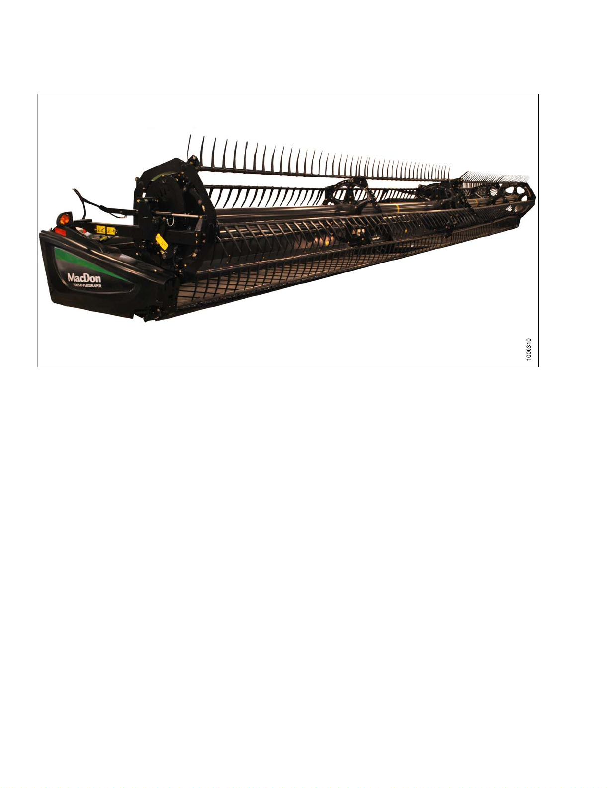
TheFD75FlexDraper
cut conditions, whether cutting on or above the ground, using a three-piece flexible frame to closely follow ground
contours.
CAREFULLYREAD ALLTHE MATERIALPROVIDED BEFOREATTEMPTINGTO UNLOAD, ASS EMBLE , OR USE
THE MACHINE.
Use this manual as your first source of information about the machine. If you follow the instructions given here,
your header will work well for many years. If you require more detailed service information, a technical manual is
available from your MacDon Dealer.
The Table of Contents and Index will guide you to specific areas of this manual. Study the Table of Contents to
familiarize yourself with how the info rmation is organized.
Keep thismanual handy for frequentreference and to pass
on to new Operators or Owners. A storage case for this
manual is located inside the header left endshield.
Call your MacDon Dealer if you need assistance,
information, or additional copies of this manual.
NOTE:
Keep your
The most
from our
our Deal
(login r
®
is specially designed as a “straight cut” header and is equipped to work well in all straight
MacDon publications up-to-date.
current version can be downloaded
website (www.macdon.com)orfrom
er-only site (https://portal.macdon.com)
equired).
Figure 1: Manual Storage Location
169894
i
i
Revision A
Page 5

List of Revisions
The following
Summary of Change Refer To
Note regarding access to updated manuals added to
Introduction
25 ft. FD75 deleted
Specificat
CA25 oil change interval revised Changing Oil in Header Drive Gearbox, page 273
Optimizing the header for straight combining canola
section added
Wing Float procedure revised
Operating in flex mode and in rigid mode sections
added
John Deere combine coupler attachment procedure
revised
nal attachments section updated
Optio
lists the changes from the previous version (169595 Revision D) of this document.
Introduction, page ii
All locations
ions table revised
3 Specifica
4.6.3 OptimizingHeader for Straight CombiningCanola,
page 48
6.14 Che
page 390
Operating In Flex Mode, page 143
Operating In Rigid Mode, page 144
5.3.1 Attaching Header to John Deere Combine, page
198
8Opti
tions, page 27
cking and Adjusting Header Wing Balance,
ons and Attachments, page 415
Cutting on the ground section revised Cutting On the Ground, page 55
Header Float section revised 4.7.3 Header Float, page 137
AHHC section reorganized 4.7.2 Auto Header Height Control, page 56
7.5 Reel Speed, page 146
4.
7.6 Ground Speed, page 147
el Speed, Ground Speed, Draper Speed and Knife
Re
eed sections revised
Sp
References to HC10 Hay Conditioner deleted
CR Feeder Deflector section revised 5.5.3 CR Feeder D eflectors, page 220
Multicoupler topic deleted Various locations
Installing and removing flighting extensions, feed
deflectors, and stripper bars moved to Maintenance
and Servicing.
Auger to Plan Clearance, and Auger Drive Chain
Tension revised
Major changes to Knife and Knife Drive sections
4.
7.7 Draper Speed, page 148
4.
.7.8 Knife Speed, page 150
4
All locations
6.7.6 Flighting Extensions, p age 298
6.10 Adapter Stripper Bars and Feed Deflectors, page
332
6.7 Auger, page 286
6.7.2 Adjusting Auger Drive Chain Tension, page 287
Various locations including 6.8 Knife and Knife Drive,
page 300
Knife hold-down clearances revised Knife Hold-Downs, page 309
169894
ii
i
Revision A
Page 6

Installing knife drive box revised Installing Knife Drive Box, page 317
Header Draper Tracking section revised 6.11.4 Adjusting Header Draper Tracking, page 337
Wing Balance section revised
General text and formatting revision s to improve
readability
Revision Page added
6.14 Checkin
page 390
Various locations throughout
List of Revisions, page iii
g and Adjusting Header Wing Balance,
Figure titles added and revised Various locations throughout
169894
v
i
Revision A
Page 7
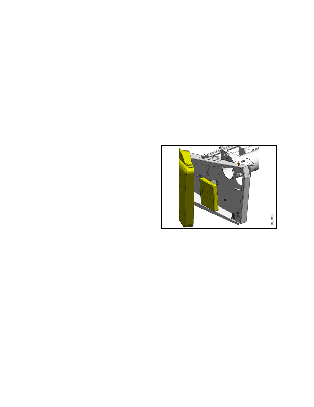
Model and Serial Number
Record the mod
wheel option (
NOTE:
Draper Heade
Header Model:
Serial Numb
Year:
The serial
drive moto
Combine Adapter
Adapter
if installed) on the lines below.
Right Hand (RH) and Left Hand (LH) designations are determined from the operator’s position, facing
forward.
r
er:
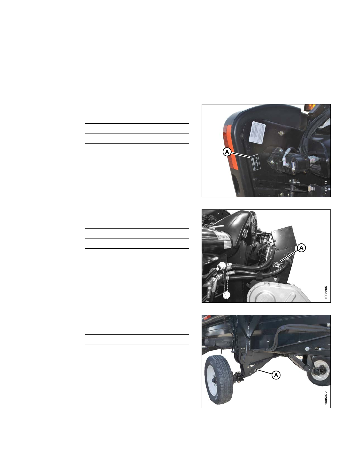
number plate (A) is located beside the knife
r on the left hand endsheet.
Model:
el nu mber, serial number, and model year of the header, combine adap ter, and transport/stabilizer
Figure 2: Header
Serial Number:
Year:
The serial number plate (A) is located on the underside
of the reservoir at the right end.
Speed Transport/Stabilizer Wheel Option
Slow
Serial Number:
r:
Yea
The serial number plate (A) is located on the right hand
axle assembly.
Figure 3: Adapter
169894
igure 4: Transport/Stabilizer Option
F
v
Revision A
Page 8

Page 9

TABLE OF CONTENT
S
Declaration of Conformity.................................................................................................................. i
Introduction......................................................................................................................................ii
Listof Revisions..............................................................................................................................iii
Model and Serial Number................................................................................................................. v
1 Safety.................................................................................................................................................... 1
1.1 Safety Alert Symbols........................................................................................................................1
1.2 Signal Words................................................................................................................................... 2
1.3 General Safety ................................................................................................................................3
1.4 Maintenance Safety......................................................................................................................... 5
1.5 HydraulicSafety.............................................................................................................................. 6
1.6 Tire Safety....................................................................................................................................... 7
1.7 Safety Signs.................................................................................................................................... 8
1.7.1 Installing Safety Decals ............................................................................................................ 8
1.8 Safety DecalLocations .................................................................................................................... 9
1.9 Interpreting Safety Signs................................................................................................................ 13
2 Reference............................................................................................................................................ 21
2.1 Definitions..................................................................................................................................... 21
2.2 Component Identification................................................................................................................ 23
2.2.1 FD75 FlexDraper
®
.................................................................................................................. 23
2.2.2 CA25Combine Adapter.......................................................................................................... 24
3 Specifications ..................................................................................................................................... 27
4 Operation............................................................................................................................................ 31
4.1 Owner/Operator Responsibilities..................................................................................................... 31
4.2 Operational Safety......................................................................................................................... 32
4.2.1 Header Safety Props.............................................................................................................. 32
4.2.2 ReelSafetyProps.................................................................................................................. 33
Engaging Reel SafetyProps............................................................................................ 33
Disengaging Reel Safety Props ....................................................................................... 34
4.2.3 Endshields............................................................................................................................. 35
Opening Endshields........................................................................................................ 35
Closing Endshields ......................................................................................................... 36
Removing Endshields ..................................................................................................... 37
Installing Endsh ields ....................................................................................................... 38
AdjustingEndshields....................................................................................................... 39
4.2.4 Linkage Covers...................................................................................................................... 40
Removing Linkage Covers............................................................................................... 40
Installing Linkage Covers ................................................................................................ 41
4.2.5 Daily Start-Up Check.............................................................................................................. 42
4.3 Break-in Period.............................................................................................................................. 43
4.4 Shutdown Procedure ..................................................................................................................... 44
4.5 Cab Controls................................................................................................................................. 45
4.6 Header Setup ................................................................................................................................ 46
4.6.1 Header Attachments ............................................................................................................... 46
4.6.2 Header Settings..................................................................................................................... 47
4.6.3 Optimizing Headerfor Straight CombiningCanola.................................................................... 48
AdjustingFeed AugerSprings ......................................................................................... 48
4.6.4 ReelSettings ......................................................................................................................... 49
4.7 Header Operating Variables ........................................................................................................... 51
4.7.1 Cutting Height........................................................................................................................ 51
Cutting OffThe Ground................................................................................................... 51
Cutting On the Ground.................................................................................................... 55
4.7.2 AutoHeaderHeightControl ....................................................................................................56
Height Sensor OutputVoltage Range – CombineRequirements ........................................ 58
169894
ii
v
Revision A
Page 10

TABLE OF CONTENT
S
AGCO6 and 7 Series Combines ..................................................................................... 61
CaseIH 2300/2500 Combines......................................................................................... 68
CaseIH 7010/8010, 7120/8120/9120, and 7230/8230/9230 Combines............................... 70
Gleaner R62/R72 Combines............................................................................................ 77
Gleaner R65/R75 Combines............................................................................................ 80
JohnDeere 50 Series Combines ..................................................................................... 89
JohnDeere 60 Series Combines ..................................................................................... 92
JohnDeere 70 Series Combines ..................................................................................... 98
JohnDeere S Series Combines......................................................................................104
Lexion 500 Series Combines..........................................................................................112
Lexion 700 Series Combines.......................................................................................... 122
New Holland Combines..................................................................................................128
Sensor Operation...........................................................................................................136
4.7.3 Header Float.........................................................................................................................137
Checking andAdjusting Header Float ............................................................................. 138
Locking/Unlocking Header Float..................................................................................... 142
Locking/Unlocking Header Wings....................................................................................143
OperatingIn Flex Mode..................................................................................................143
OperatingIn Rigid Mode.................................................................................................144
4.7.4 Header Angle........................................................................................................................145
Controlling Header Angle ............................................................................................... 146
4.7.5 ReelSpeed...........................................................................................................................146
Optional Reel Drive Sprockets........................................................................................147
4.7.6 Ground Speed......................................................................................................................147
4.7.7 Draper Speed.......................................................................................................................148
AdjustingSide Draper Speed..........................................................................................148
AdjustingFeed Draper Speed.........................................................................................149
4.7.8 Knife Speed ..........................................................................................................................150
Checking Knife Speed....................................................................................................151
4.7.9 ReelHeight...........................................................................................................................151
4.7.10 Reel Fore-AftPosition ...........................................................................................................152
AdjustingReel Fore-Aft Position.....................................................................................152
Repositioning Fore-AftCylinders.....................................................................................153
4.7.11 ReelTinePitch......................................................................................................................156
Choosing a ReelCam Setting......................................................................................... 156
AdjustingReel Cam.......................................................................................................158
4.7.12 Crop Dividers........................................................................................................................159
Removing Crop Dividers from Header withLatch Option ..................................................159
Removing Crop Dividers from Header without Latch Option..............................................160
Installing Crop Dividers on Header with Latch Option .......................................................160
Installing Crop Dividers on Header without Latch Option...................................................162
4.7.13 Crop Divider Rods.................................................................................................................163
Removing Crop Divider Rods .........................................................................................164
Using Rice Dividers........................................................................................................164
4.8 Leveling the Header......................................................................................................................165
4.9 Unplugging Cutterbar ....................................................................................................................167
4.10 Unplugging Adapter......................................................................................................................168
4.11 Upper Cross Auger (UCA).............................................................................................................169
4.11.1 Removing Beater Bars...........................................................................................................169
4.11.2 Installing Beater Bars ............................................................................................................170
4.12 Transporting Header ....................................................................................................................171
4.12.1 Transporting Header on Combine........................................................................................... 171
4.12.2 Towing ..................................................................................................................................171
AttachingHeaderto Towing Vehicle................................................................................172
169894
iii
v
Revision A
Page 11

TABLE OF CONTENT
S
Towing the Header ......................................................................................................... 172
4.12.3 Convertingfrom Transport to FieldPosition............................................................................. 173
Removing Tow-Bar ........................................................................................................173
Storing Tow-Bar.............................................................................................................174
Moving Front(Left)Wheels into Field Position................................................................. 175
Moving Rear (Right) Wheels intoField Position................................................................177
4.12.4 Convertingfrom Field to TransportPosition............................................................................. 179
Moving Front(Left)Wheels into Transport Position .......................................................... 179
Moving Rear (Right) Wheels intoTransport Position.........................................................181
AttachingTow-Bar..........................................................................................................184
4.13 Storage ........................................................................................................................................187
5 Header Attachment/Detachment ........................................................................................................189
5.1 Adapter Setup ..............................................................................................................................189
5.1.1 Using Flighting Extensions.....................................................................................................189
5.1.2 Using Stripper Bars...............................................................................................................189
5.1.3 AdjustingAuger Speed..........................................................................................................190
5.2 CaseIH Combines........................................................................................................................191
5.2.1 AttachingHeaderto Case IH Combine ...................................................................................191
5.2.2 DetachingHeader from Case IH Combine..............................................................................195
5.3 John Deere Combines .................................................................................................................. 198
5.3.1 AttachingHeaderto John Deere Combine ..............................................................................198
5.3.2 DetachingHeader from John Deere Combine.........................................................................201
5.4 Lexion Combines..........................................................................................................................205
5.4.1 AttachingHeaderto LexionCombine......................................................................................205
5.4.2 DetachingHeader from Lexion Combine.................................................................................209
5.5 New HollandCombines .................................................................................................................213
5.5.1 AttachingHeaderto New Holland CR/CX Combine.................................................................213
5.5.2 DetachingHeader from New Holland Combine........................................................................216
5.5.3 CR Feeder Deflectors............................................................................................................ 220
5.6 AGCOCombines..........................................................................................................................221
5.6.1 AttachingHeaderto AGCO Combine......................................................................................221
5.6.2 DetachingHeader from AGCO Combine.................................................................................226
5.7 Attachingand Detaching Header FromAdapterand Combine .........................................................230
5.7.1 DetachingHeader from Adapter and Combine........................................................................230
5.7.2 AttachingHeaderto Adapter and Combine .............................................................................235
6Maint
6.1 Prepa
6.2 Maint
6.
enance and Servicing................................................................................................................241
ration for Servicing...............................................................................................................241
enance Specifications...........................................................................................................242
6.2.
6.2.
6.2.
6.2
6.
3
6.
6.
1
2
3
.4
2.5
intenanceRequirements...........................................................................................................257
Ma
3.1
3.2
ersion Chart.................................................................................................................. 243
Conv
mmended Fluids and Lubricants..................................................................................... 244
Reco
ue Specifications ............................................................................................................244
Torq
olt Torque Specifications....................................................................................... 244
SAE B
ic Bolt Specifications ...............................................................................................247
Metr
ic Bolt Specifications Bolting into Cast Aluminum ......................................................249
Metr
re-Type Hydraulic Fittings..........................................................................................249
Fla
ing Boss (ORB)Hydraulic Fittings (Adjustable)..........................................................251
O-R
ing Boss (ORB)Hydraulic Fittings (Non-Adjustable)...................................................253
O-R
ing Face Seal (ORFS) Hydraulic Fittings ................................................................... 254
O-R
talling a Roller Ch ain.........................................................................................................255
Ins
stalling a Sealed Bearing .................................................................................................... 256
In
intenanceSchedule/Record...............................................................................................258
Ma
eak-In Inspection...............................................................................................................260
Br
169894
x
i
Revision A
Page 12

TABLE OF CONTENT
S
6.3.3 Preseason/Annual Service.....................................................................................................260
6.3.4 End of Season Service..........................................................................................................260
6.3.5 Checking Hydraulic Hoses andLines......................................................................................262
6.3.6 Lubrication and Servicing.......................................................................................................262
Service Intervals ............................................................................................................263
Greasing Procedure.......................................................................................................270
Lubricating AugerDrive Chain........................................................................................271
Lubricating Header Drive Gearbox.................................................................................. 272
6.4 Hydraulics....................................................................................................................................274
6.4.1 Reservoir..............................................................................................................................274
Checking OilLevel......................................................................................................... 274
Adding Oil.....................................................................................................................275
Changing Oil.................................................................................................................275
6.4.2 Changing OilFilter ................................................................................................................276
6.5 Electrical......................................................................................................................................278
6.5.1 ReplacingLight Bulbs............................................................................................................278
6.6 Header Drive................................................................................................................................279
6.6.1 Removing Driveline ...............................................................................................................279
6.6.2 Installing Driveline .................................................................................................................280
6.6.3 Removing Driveline Guard.....................................................................................................281
6.6.4 Installing Driveline Guard.......................................................................................................283
6.6.5 AdjustingTension on Gearbox Drive Chain .............................................................................285
6.7 Auger...........................................................................................................................................286
6.7.1 AdjustingAuger to Pan Clearance .......................................................................................... 286
6.7.2 AdjustingAuger Drive ChainTension......................................................................................287
6.7.3 Removing Auger DriveChain ................................................................................................. 288
6.7.4 Installing Auger Drive Chain...................................................................................................292
6.7.5 Auger Tines ..........................................................................................................................294
Removing Feed Auger Tines .......................................................................................... 294
Installing Feed Auger Tines............................................................................................296
ReplacingAuger Tine Guides .........................................................................................297
6.7.6 FlightingExtensions..............................................................................................................298
Installing Flighting Extensions......................................................................................... 298
Removing Flighting Extensions .......................................................................................299
6.8 Knife and Knife Drive....................................................................................................................300
6.8.1 ReplacingKnife Section.........................................................................................................300
6.8.2 Removing Knife.....................................................................................................................302
6.8.3 Removing Knifehead Bearing.................................................................................................302
6.8.4 Installing Knifehead Bearing...................................................................................................303
6.8.5 Installing K nife ......................................................................................................................303
6.8.6 Spare Knife...........................................................................................................................304
6.8.7 Knife Guards.........................................................................................................................304
AdjustingKnife Guards...................................................................................................305
ReplacingPointed Guards on a Single-Knife Header........................................................305
ReplacingPointed Guards on a Double-Knife Header ......................................................306
ReplacingStub Guards on a Single-Knife Header ............................................................ 307
ReplacingStub Guards on a Double-Knife Header...........................................................308
Knife Hold-Downs .......................................................................................................... 309
6.8.8 Knife Drive Belt..................................................................................................................... 311
Removing Knife DriveBelt (Non-Timed)..........................................................................311
Installing Knife Drive Belt................................................................................................312
Tensioning Knife Drive Belts...........................................................................................313
6.8.9 Knife Drive Box.....................................................................................................................314
Mounting Bolts...............................................................................................................314
169894
x
Revision A
Page 13

TABLE OF CONTENT
S
Removing Knife DriveBox.............................................................................................. 314
Removing Knife DriveBox Pulley .................................................................................... 316
Installing Knife Drive B o x Pulley...................................................................................... 317
Installing Knife Drive B ox................................................................................................317
Changing Oilin Knife Drive Box ...................................................................................... 320
6.8.10 Knifehead Shield ................................................................................................................... 320
Installing Knifehead Shield ............................................................................................. 321
6.9 Adapter FeedDraper....................................................................................................................322
6.9.1 ReplacingAdapter Feed Draper.............................................................................................322
6.9.2 AdjustingFeed Draper Tension ..............................................................................................323
6.9.3 Adapter Drive Roller..............................................................................................................324
Removing Adapter FeedDraperDrive Roller................................................................... 324
Installing Adap ter Feed Draper Drive Roller.....................................................................326
ReplacingAdapterDrive Roller Bearing .......................................................................... 326
6.9.4 Adapter Idler Roller ...............................................................................................................328
Removing Adapter FeedDraperIdler Roller....................................................................328
ReplacingAdapterFeed Draper IdlerRollerBearing........................................................329
Installing Adap te r Feed Draper Idler Roller ......................................................................330
6.10 Adapter Stripper Bars an d Feed Deflectors.....................................................................................332
6.10.1 Installing Stripper Bars...........................................................................................................332
6.10.2 Removing Stripper Bars .........................................................................................................332
6.10.3 Replacing Feed Deflectors ..................................................................................................... 333
6.11 Header Drapers............................................................................................................................334
6.11.1 Removing SideDraper..........................................................................................................334
6.11.2 Installing S id e Draper ............................................................................................................335
6.11.3 Adjusting Side DraperTension ...............................................................................................336
6.11.4 Adjusting Header Draper Tracking..........................................................................................337
6.11.5 Adjusting Deck Height...........................................................................................................339
6.11.6 Draper RollerMaintenance....................................................................................................340
Inspecting DraperRollerBearing ....................................................................................340
SideDraperDeck Idler Roller.........................................................................................341
SideDraperDrive Roller.................................................................................................343
6.12 Reeland Reel Drive......................................................................................................................348
6.12.1 Reel Clearance to Cutterbar...................................................................................................348
Measuring Reel Clearance.............................................................................................348
AdjustingReel Clearance ............................................................................................... 350
6.12.2 Reel Frown...........................................................................................................................350
AdjustingReel Frown.....................................................................................................351
6.12.3 Centering theReel ................................................................................................................352
Centeringthe Reel......................................................................................................... 352
6.12.4 Reel Drive Chain...................................................................................................................352
AdjustingChain Tension on Double ReelDrive................................................................352
ReplacingChain on Double ReelDrive............................................................................354
6.12.5 Reel Drive Sprocket ..............................................................................................................359
ReplacingReel Drive Sprocket on Double Reel ...............................................................359
6.12.6 Reel Drive U-Joint.................................................................................................................362
Removing U-Joint..........................................................................................................363
Installing U-Joint............................................................................................................364
6.12.7 Reel Drive Motor...................................................................................................................366
Removing Double ReelDrive Motor ................................................................................ 366
Installing Double Reel Drive Motor ..................................................................................368
6.12.8 Reel Speed Sensor ...............................................................................................................370
ReplacingJohn DeereReel Speed Sensor- Double Reel.................................................370
ReplacingLexion 500/700SeriesReel Speed Sensor - Double Reel.................................371
169894
i
x
Revision A
Page 14

TABLE OF CONTENT
S
ReplacingAGCO Reel Speed Sensor - DoubleReel........................................................372
6.12.9 Reel Tines............................................................................................................................373
Removing Steel Tines....................................................................................................374
Installing Steel Tines......................................................................................................374
Removing Plastic Fingers............................................................................................... 375
Installing Plastic Fingers.................................................................................................375
6.12.10 TineTubeBushings...............................................................................................................376
Removing Bushings from 5-, 6- or 9-Bat Reels................................................................ 376
Installing Bushings on 5-, 6- or 9-Bat Reels .....................................................................379
6.12.11 Reel Endshields....................................................................................................................384
ReplacingEndshield...................................................................................................... 384
ReplacingSupport......................................................................................................... 385
6.13 Transport System(Optional)..........................................................................................................387
6.13.1 Checking Wheel Bolt Torque..................................................................................................387
6.13.2 Checking AxleBolt Torque.....................................................................................................388
6.13.3 Checking Tire Pressure .........................................................................................................388
6.14 Checking andAdjusting Header Wing Balance...............................................................................390
6.14.1 Checking WingBalance.........................................................................................................390
6.14.2 Adjusting Wing Balance.........................................................................................................395
7 Troubleshooting.................................................................................................................................399
7.1 Crop Loss at Cutterbar..................................................................................................................399
7.2 Cutting Action and Knife Components ............................................................................................ 401
7.3 Reel.............................................................................................................................................404
7.4 Header and Drapers .....................................................................................................................406
7.5 Cutting Edible Beans ....................................................................................................................410
8 Options
8.1 O ptions
8.1.1 Cutterb
8.1.2 Divide
8.1.3 Draper
8.1.4 Draper
8.1.5 Europe
8.1.6 CA25 Fe
8.1.7 Knife
8.1.8 Lodge
8.1.9 Reel E
8.1.1
8.1.1
8.1.
8.1.
8.1.
8.1.
8.1.
8.1.
8.1
and Attachments ..................................................................................................................415
and Attachments..............................................................................................................415
ar Plastic Wear Strips................................................................................................. 415
r LatchKit .................................................................................................................... 415
Deflector (Narrow)...................................................................................................... 416
Deflector (Wide).........................................................................................................416
an Adapter SealKit.....................................................................................................416
ed Auger Flighting .................................................................................................... 417
headShield...................................................................................................................417
d Crop Reel Finger Kit .................................................................................................. 417
ndshield Kit.................................................................................................................418
12
13
14
15
16
17
.18
0
1
PR15 T
Rice D
Rock
Shor
Stab
Stab
Stub
Uppe
Ver
ine Tube Reel Conversion Kit......................................................................................418
ivider Rods ................................................................................................................. 418
Retarder.......................................................................................................................419
t Brace Kit For Center Reel Arm ...................................................................................... 419
ilizer Wheels ..................................................................................................................419
ilizer/Slow Speed Transport Whee ls.................................................................................420
Guard Conversion Kit .................................................................................................... 420
r CrossAuger (UCA) .....................................................................................................421
tical Knife Mounts.............................................................................................................421
9 Unloading and Assembly ...................................................................................................................423
Index ..................................................................................................................................................425
169894
ii
x
Revision A
Page 15

1Safety
1.1 Safety Alert Symbols
This safety alert symbol indicates important safety
messages in this manual and on safety signs on
the header.
This symbol means:
• ATTENTION!
• BECOME ALERT!
• YOUR SAFETY IS INVOLVED!
Carefully read and follow the safety message
accompanying this symbol.
Why is safety important to you?
• Ac cidents disable and kill.
• Accidents cost.
• Accidentscanbeavoided.
Figure 1.
1: Safety Sym bol
169894
1
Revision A
Page 16

SAFETY
1.2 Signal Words
Three signal words, DANGER, WARNING, and CAUTION, are used to alert you to hazardous situations. The
appropriate signal word for each situation has been selected using the following guidelines:
DANGER
Indicates an imminently hazardous situation that, if not avoided, will result in death, or serious injury.
WARNING
Indicates a pote
mayalsobeused
ntially hazardous situation that, if not avoided, could result in death, or serious injury. It
to alert against unsafe practices.
CAUTION
Indicates a potentially hazardous situation that, if not avoided, may result in minor, or moderate injury. It
may be used to alert against unsafe practices.
169894
2
Revision A
Page 17
SAFETY
1.3 General Safety
CAUTION
The following are general farm safety precautions
that should be part of your operating procedure for
all types of machinery.
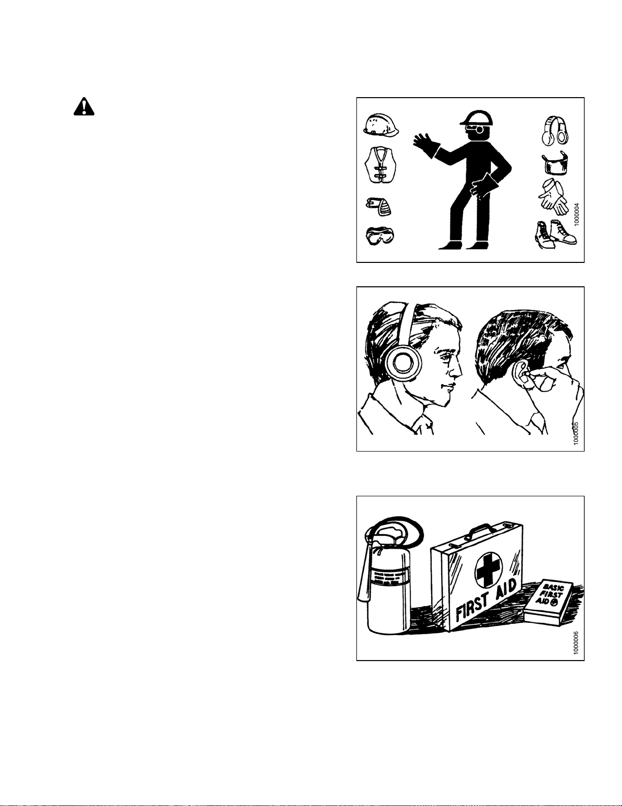
Protect yourself
• When assembling, operating, and servicing machinery,
wear all the protective clothing and personal safety
devices that COULD be necessary for the job at hand.
Don’t take chances.
• You may need:
– A hard hat
– Protective footwear with slip resistant soles
– Protective glasses or goggles
– Heavy gloves
– Wet weather gear
– A respirator or filter mask
– Hearing protection
Be aware that exposure to loud noise can cause
impairment or loss of hearing. Wearing suitable
hearing protection devices such as ear muffs or ear
plugs. These will help protect against objectionable
or loud noises.
•Provideafirs
• Keep a fire ext
fire extingui
its proper us
• Keep young c
all times.
t aid kit for use in case of emergencies.
inguisher on the machine. Be sure the
sher is properly maintained. Be familiar with
e.
hildren away from the machinery at
Figure 1.2
Figure 1.3: Safety Equipment
: Safety Equipment
•Beawaretha
Operator is
time to cons
signs of fa
169894 3 Revision A
t accidents often happen when the
tiredorinahurrytogetfinished. Take the
ider the safest way. Never ignore warning
tigue.
Figure 1.4: Safety Equipment
Page 18
SAFETY
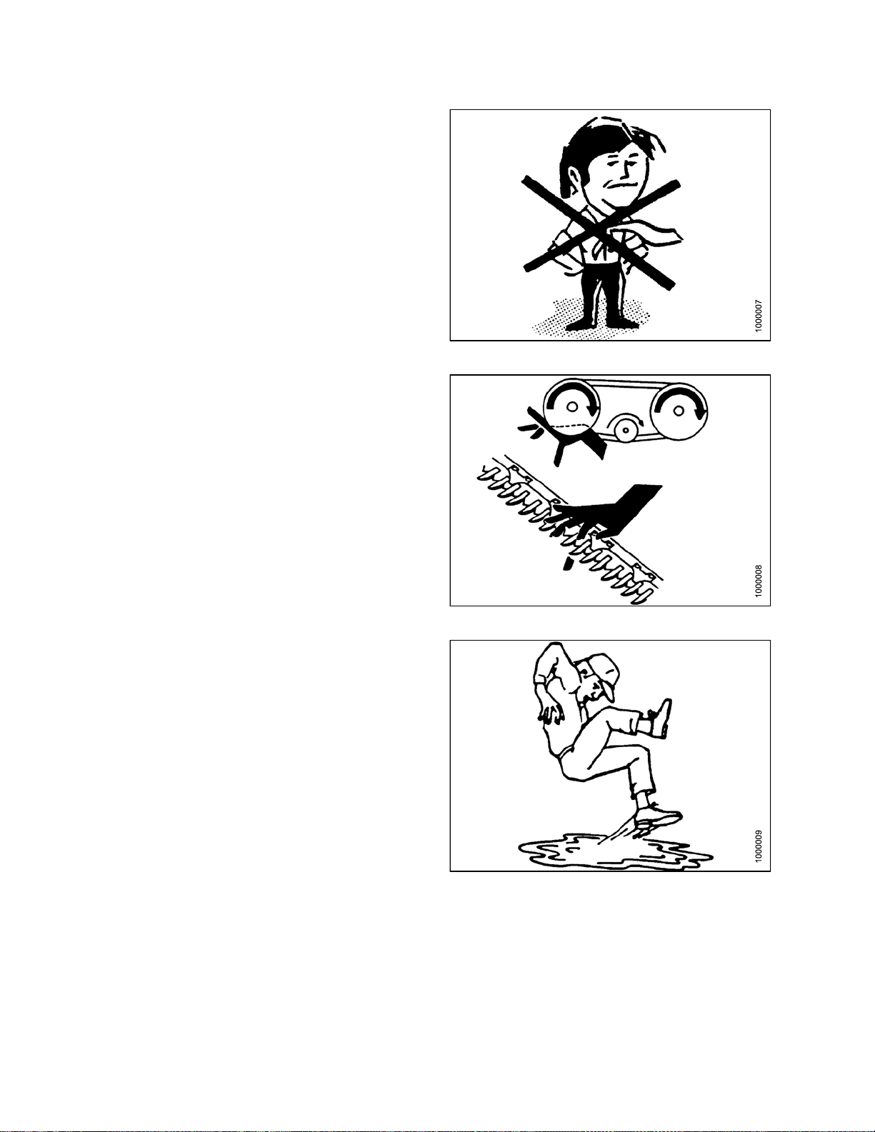
•Wearclosefitting clothing and cover long hair. Never
wear dangling items such as scarves or bracelets.
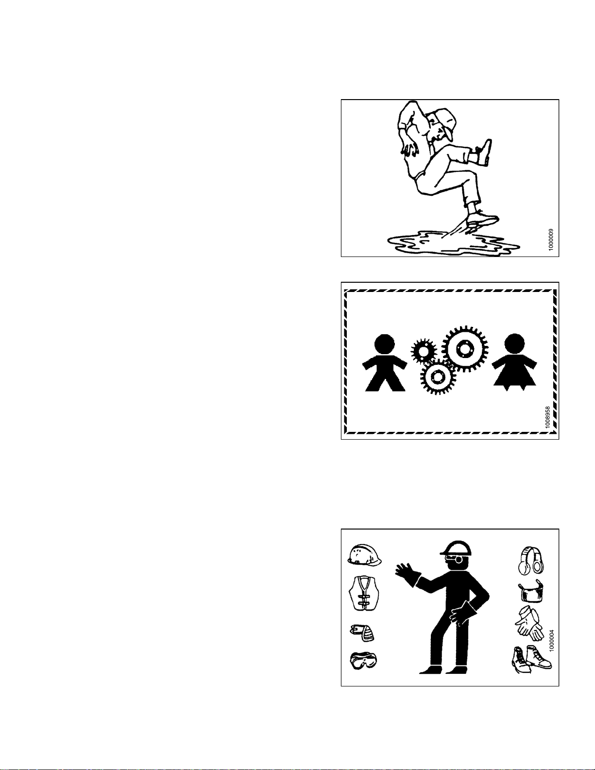
• Keep all shields in place. Never alter or remove safety
equipment. Make sure driveline guards can rotate
independently of the shaft and can telescope freely.
• Use only serviceand repair parts,made, or approvedby
the equipment manufacturer. Substituted parts may not
meet strength, design, or safety requirements.
• Keep hands, feet, clothing, and hair away from moving
parts. Neve r attempt to clear obstructions or objects,
from a machine while the engine is running.
•DoNOT modify the machine. Non-authorized
modifications may impair machine function and/or
safety. It may also shorten the machine’s life.
Figure 1.5: Safety around Equipment
• Stop the engineand remove the keyfrom ignition before
leaving operator ’s seat for any reason. A child or even
a pet could engage an idling machine.
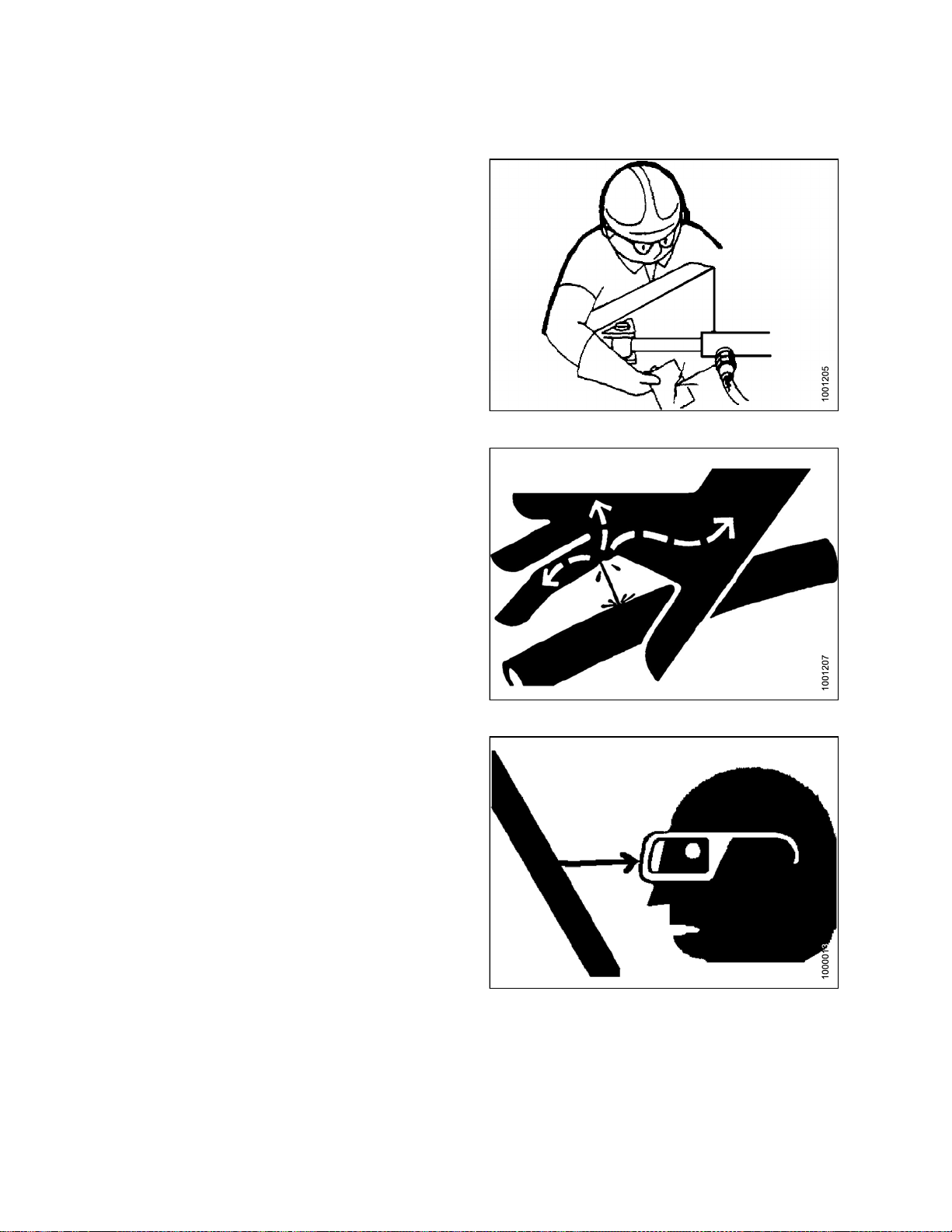
• Keep the area used for servicing machinery clean and
dry. Wet or oily floors are slippery. Wet spots can be
dangerous when working with electrical equipment.
Be sure all electrical outlets and tools are properly
grounded.
• Keep work area well lit.
• Keep machinery clean. Straw and chaff, on a hot
engine, are a fire hazard. Do NOT allow oil or grease to
accumulate on service platforms, ladders, or controls.
Clean machines before storage.
• Never use gasoline, naphtha, or anyvolatile material for
cleaningpurposes. These materialsmay be toxic and/or
flammable.
• When storing machinery, cover sharp or extending
components to prevent injury from accidental contact.
Figure 1.6: Safety around Equipment
Figure 1.7: Safety around Equipment
169894
4
Revision A
Page 19
SAFETY
1.4 Maintenance Safety
To ensure your safety while maintaining the machine:
• Review the operator’s manual and all safety items
before operation and/or maintenance of the machine.
• Place all controls in Neutral, stop the engine, set the
park brake, remove the ignition key, and wait for all
moving parts to stop before servicing, adjusting, and/or
repairing.
• Follow good shop practices:
– Keep service area clean and dry.
– Be sure electrical outlets and tools are
properly grounded.
– Use adequate light for the job at hand.
• Relieve pressure fromhydraulic circuitsbefore servicing
and/or disconnecting the machine.
• Befo re applying pressure to a hydraulic system , make
sureall components are tight and that steellines, hoses,
and couplings are in good condition.
Figure 1.8: Safety around Equipment
• Keep hands, feet, clothing, and hair away from all
moving and/or rotating parts.
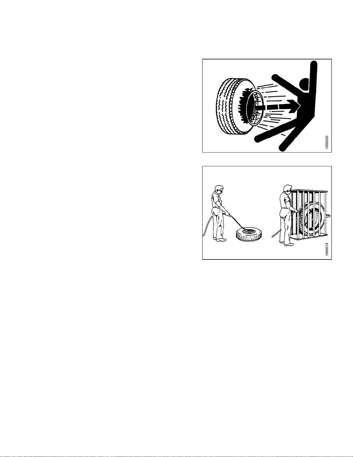
• Clear the area of bystand ers especially children w hen
carrying out any maintenance and repairs or when
making any adjustments.
• Install transport lock or place safety stands under the
frame before working under the header.
• If more than one person is servicing the machine at the
same time, be aware that rotating a driveline or other
mechanically driven component by hand (for example,
accessing a lube fitting) will cause drive components in
other areas (belts, pulleys, and knife) to move. Stay
clear of driven components at all times.
• Wear protective gea
• Wear heavy gloves w
r when working on the machine.
hen working on knife components.
Figure 1.9: Eq
uipment NOT Safe for Children
Figure 1.10: Saf
169894 5 Revision A
ety Equipment
Page 20
SAFETY
1.5 Hydraulic Safety
• Always place all hydraulic controls in Neutral
before dismounting.
• Make sure that all components in the hydraulic system
are kept in good condition and clean.
• Replace any worn, cut, abraded, flattened, or crimped
hoses and steel lines.
•DoNOT attempt any makeshift repairs to the hydraulic
lines, fittings,or hosesby usingtapes, clamps,cements,
or welding. The hydraulic system operates under
extremely high pressure. Such makeshift repairs will fail
suddenly and create a hazardous and unsafe condition.
Figure 1.11: Checking Hydraulic Leaks
•Wearprope
for a highcardboar
and ident
•Ifinjure
hydrauli
Serious
hydraul
• Before applying pressure to a hydraulic system, make
sure all components aretight andthat steel lines,hoses,
and couplings are in good condition.
r hand and eye protection when searching
pressure hydraulic leak. U se a piece of
d a s a backstop instead of hands to isolate
ify a leak.
d by a concentrated high-pressure stream of
c fluid, seek medical attention immediately.
infection or toxic reaction can develop from
ic fluid piercing the skin.
Figure
1.12: Hydraulic Pressure Hazard
ure 1.13: Safety Glasses
Fig
169894 6 Revision A
Page 21
SAFETY
1.6 Tire Safety
• Failure to followproper procedures when mountinga tire
on a wheel or rim can produce an explosion that may
result in serious injury or death.
•DoNOT attempt to mount a tire unless you have the
proper training and equipment.
• Haveaqualified tire dealer or repair service perform
required tire maintenance.
Figure 1.14: Over-Inflated Tire
Figure 1.15: Safely Filling a Tire with Air
169894
7
Revision A
Page 22

SAFETY
1.7 Safety Signs
• Keep safety signs clean and legible at all times.
• Replace safety signs that are missing or
become illegible.
• If original parts on which a safety sign was installed are
replaced, be sure the repair part also bears the current
safety sign.
• Safety signs are available from your Dealer
Parts Department.
1.7.1 Installing Safety Decals
Figure 1.16: Operator’s Manual Decal
To instal
1. Clean and
2. Decide on
3. Remove t
4. Place th
5. Prick sm
l a safety decal, follow these steps:
e sign in position and slowly peel back the remaining paper, smoothing the sign as it is applied.
dry the installation area.
the exact location before you remove the decal backing paper.
he smaller portion of the split backing paper.
all air pockets with a pin and smooth out.
169894 8 Revision A
Page 23
1.8 Safety Decal Locations
SAFETY
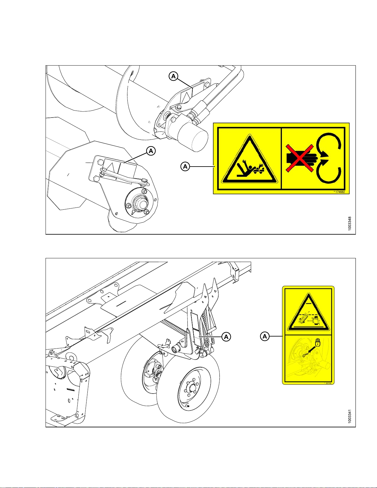
Figure 1
A - MD #174682
.17: Upper Cross Auger
Figure 1.18: Slow Speed Transport
D #220799
A-M
169894 9 Revision A
Page 24

SAFETY
Figure 1.19: Slow Speed Transport Tow-Bar
A - MD #220797 B - MD #220798
Figure 1.20: Vertical Knife
A - MD #174684
169894 10 Revision A
Page 25

SAFETY
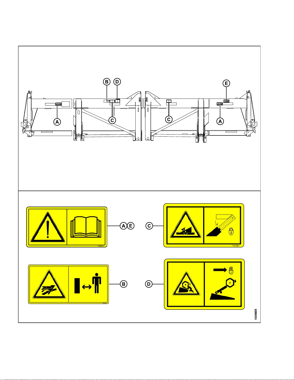
Figure 1.21: Endsheets, Reel Arms, Backsheet
A - MD #131393 B - MD #174632 C - MD #184371 D - MD #184371 (DK Only)
E - MD #131392 (2 PLC’s) F - MD #131391 (2 PLC’s) G - MD #174436 H - MD #184371 (DK 2 PLC’s)
169894
1
1
Revision A
Page 26
SAFETY
Figure 1.22: Back Tube
A - MD #184372 B - MD #166466 C - MD #131391
D - MD #131392 E - MD #184372 (Split Frame)
169894
2
1
Revision A
Page 27
SAFETY
1.9 Interpreting Safety Signs
Inthe safetysignexplanations below, (a)refers to thetop or
left position panel, (b) refers to the bottom or right position
of the safety decal depending on decal orientation.
NOTE:
If there are more than two panels in a decal, the
lettering will continue downward or to the right,
depending on decal orientation.
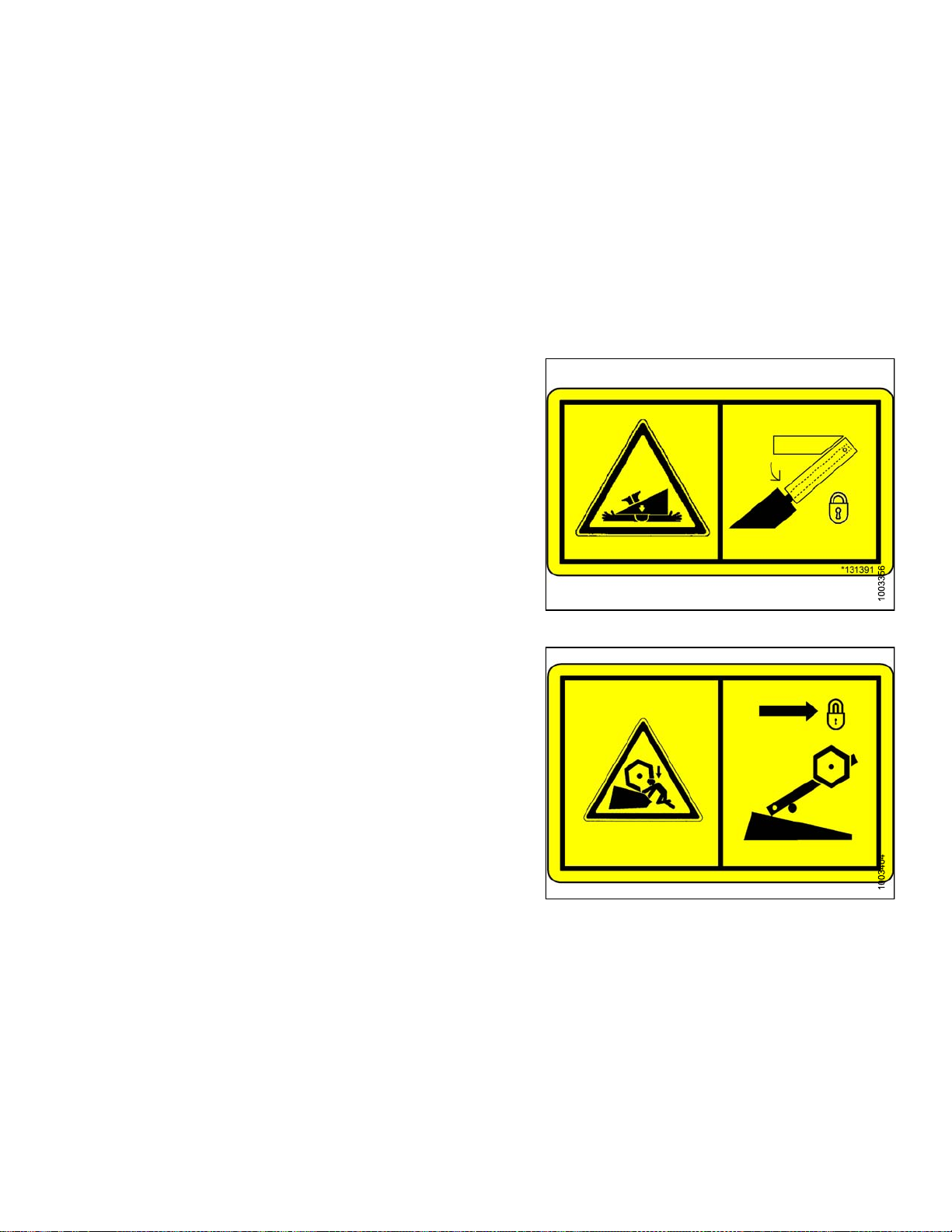
1. MD #131391
a. Crushing hazard.
b. DANGER
• Rest header on ground or engage safety props
before going under unit.
2. MD #131392
a. Crushing hazard.
b. WARNING
• To avoid injury from fall of raised reel; fully
raise reel, stop the engine, remove the key,and
engage safety prop on each reel support arm
before working on or under reel.
• Refer to header operator’s manual.
Figure 1.23: MD #131391
Figure 1.24: MD #131392
169894 13 Revision A
Page 28

3. MD #131393
a. Reel hazard.
b. WARNING
• To avoid in jury from fall of raised re el; fully
raise reel, stop the engine, remove the key, and
engage safety prop on each reel support arm
before working on or under reel.
• Refer to header operator’s manual.
4. MD #166466
a. High pressure oil hazard.
b. WARNING
Do not go near leaks.
SAFETY
Figure 1.25: MD #131393
• High pressure oil easily punctures skin causing
serious injury, gangrene, or death.
• If injured, seek emergency medical help.
Immediate surgery is required to remove oil.
• Do not use finger or skin to check for leaks.
• Lower load or relieve hydraulic pressure before
loosening fittings.
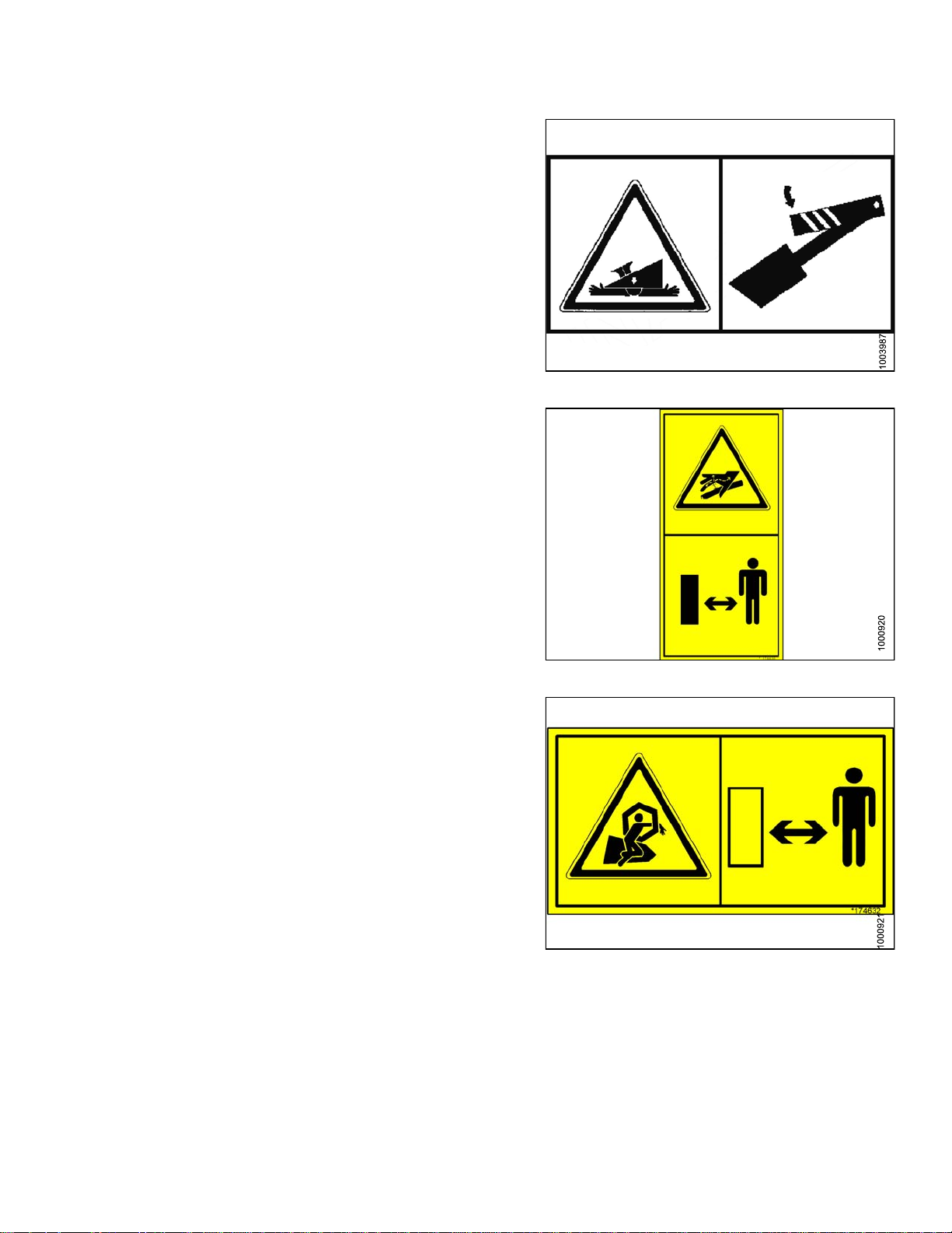
5. MD #174432
a. Reel hazard.
b. WARNING
• To avoid in jury from fall of raised re el; fully
raise reel, stop the engine, remove the key, and
engage m echanical lock on each reel support
arm before working on or under reel.
• See operator’s manual.
Figure 1.26: MD #166466
Figure 1.27: MD #174432
169894
4
1
Revision A
Page 29
6. MD #174434
a. Header hazard.
b. DANGER
• Rest header on ground or engage mechanical
locks before going under unit.
7. MD #174436
a. High pressure oil hazard.
b. WARNING
Do not go near leaks.
SAFETY
Figure 1.28: MD #174434
• High pressure oil easily punctures s kin causing
serious injury, gangrene, or death.
• If injured, seek emergency medical help.
Immediate surgery is required to remove oil.
• Do not use finger or skin to check for leaks.
• Lower load or relieve hydraulic pressure before
loosening fittings.
8. MD #174632
a. Reel entanglement hazard.
b. CAUTION
• To avoid injury from entanglement with rotating
reel, stand clear of header while machine
is running.
Figure 1.29: MD #174436
Figure 1.30: MD #174632
169894 15 Revision A
Page 30
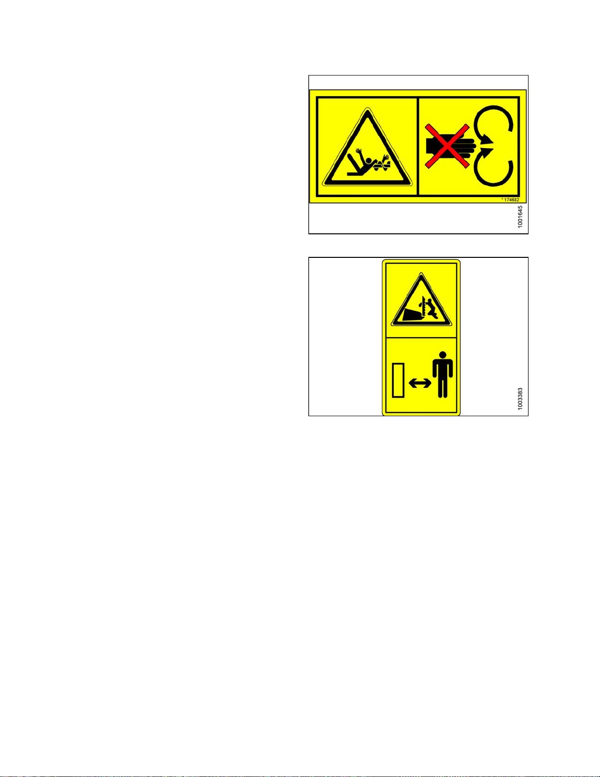
9. MD #174682
a. Auger entanglement hazard.
b. CAUTION
• To avoid injury from entanglement with rotating
auger, stand clear of header while machine
is running.
10. MD #174684
a. Sharp component hazard.
b. CAUTION
• Wear heavy canvas or leather gloves when
working with knife.
SAFETY
Figure 1.31: MD #174682
• Be sure no one is near the vertical knife when
removing or rotating knife.
Figure 1.32: MD #174684
169894 16 Revision A
Page 31

11. MD #184372
a. General hazard pertaining to machine operation
and servicing.
b. CAUTION
To avoid injury or death from improper or unsafe
machine operation:
• Read theoperator’s manualand follow allsafety
instructions. If you do not have amanual, obtain
one from your Dealer.
• Do not allow untrained persons to operate
the machine.
SAFETY
• Review safety instructions with all
Operators annually.
• Ensure that all safety signs are installed
and legible.
• Make certain everyone is clear of machine
before starting engine and during operation.
• Keep riders off the machine.
• Keep all shields in place and stay clear of
moving parts.
• Disengage header drive, put transmission in
Neutral, and wait for all movement to stop
before leaving operator’s position.
• Shut off the engine and remove the key from
ignition before servicing, adjusting, lubricating,
cleaning, or unplugging machine.
• Engage safety props to prevent lowering
of raised unit before servicing in the
raised position.
• Use slow moving vehicle emblem and flashing
warning lights when operating on roadways
unless prohibited by law.
Figure 1.33: MD #184372
12. MD #184422
a. Keep shields in place hazard.
b. WARNING
• Toavoid injury, stop the engine and remove the
key before opening power drive system shield.
• Keep all shields in place.
169894
Figure 1.
7
1
34: MD #184422
Revision A
Page 32

13. MD #190546
a. Slippery surface.
b. WARNING
Do not place foot.
• Do not use this area as a step or platform.
• Failure to comply could result in serious injury
or death.
14. MD #193147
a. Transport/roading hazard.
b. WARNING
• Ensure tow-bar lock mechanism is locked.
SAFETY
Figure 1.35: MD #190546
Figure 1.36: MD #193147
169894 18 Revision A
Page 33

15. MD #194521
a. Auger entanglement hazard.
b. CAUTION
• To avoid injury from entanglement with rotating
auger, stand clear of header while machine
is running.
c. General hazard pertaining to machine operation
and servicing
d. CAUTION
• Read the operator’s manual and follow safety
instructions. If you do not have amanual, obtain
one from your Dealer.
• Do not allow untrained persons to operate
the machine.
• Review safety instructions with all
Operators annually.
• Ensure that all safety signs are installed
and legible.
SAFETY
• Make certain everyone is clear of machine
before starting engine and during operation.
• Keep riders off the machine.
• Keep all shields in place and stay clear of
moving parts.
• Disengage header drive, put transmission in
Neutral, and wait for all movement to stop
before leaving operator’s position.
• Stop the engine and remove the key from
ignition before servicing, adjusting, lubricating,
cleaning, or unplugging machine.
• Engage locks to prevent lowering of header or
reel before servicing in the raised position.
• Use slow moving vehicle emblem and flashing
warning lights when operating on roadways
unless prohibited by law.
Figure 1.
37: MD #194521
169894 19 Revision A
Page 34

16. MD #220797
a. Tipping hazard in transport mode.
b. WARNING
• Read the operator’s manual for more
information on potential tipping or roll-over of
header while transporting.
17. MD #220798
a. Loss of control hazard in transport.
b. CAUTION
• Do not tow the header with a dented or
otherwise damaged tow pole (the circle with the
red X shows a dent in the pole).
SAFETY
Figure 1.38: MD #220797
• Consult the operator’s manual for
more information.
18. MD #220799
a. Transport/roading hazard.
b. WARNING
• Ensure tow-bar lock mechanism is locked.
Figure 1.39: MD #220798
Figure 1.40: MD #220799
169894 20 Revision A
Page 35

2 Reference
2.1 Definitions
The following terms and acronyms may be used in this manual.
Term
AHHC Automatic H
API American Petroleum Institute.
ASTM American S
Bolt
Center-link
CGVW Combined vehicle gross weight.
D-Series header
DK
DKD
DDD Doubl
DR Double reel.
eries header MacDon FlexDraper
FD-S
Finger tight
FFFT
Definition
eader Height Control
ociety of Testing and Materials.
A headed and externally threaded fastener that is designed to be paired with a nut.
Ahydraul
and the ma
MacDon rigid draper header.
Double
Double-knife drive.
Finger tight is a reference position w here sealing surfaces or components are
making contact with each other and the fitting has been tightened to a point where
the fitting is no longer loose.
Flats from finger tight.
ic cylinder or manually adjustable turnbuckle type link between the header
chine to which it is attached. It is used to change header angle.
knife.
e draper drive.
®
header.
L
GS
GVW Gross vehicle weight.
Hard joint
Header A machine that cuts crop and feeds it into an attached combine.
Hex key
HDS Hydraulic deck shift.
hp Horsepower.
ISC Intermediate Speed Control.
JIC
Knife
n/a
Nut An internally threaded fastener that is designed to be paired with a bolt.
ound speed lever.
Gr
A joint made with the use of a fastener where the joining materials are
highly incompressible.
A hex key or Allen key (also known by various other synonyms) is a tool of
hexagonal cross-section used to drive bolts and screws that have a hexagonal
socket in the head (internal-wrenching hexagon drive).
Joint Industrial Council: a standards body that developed the standard sizing and
shape for original 37° flared fitting.
A cutting device which uses a reciprocating cutter. Also called a s ickle.
Not applicable.
169894
1
2
Revision A
Page 36

REFERENCE
Term
NPT
ORB
ORFS
PTO Power Take
RoHS (Reduction of
Hazardous Substances)
Definition
National Pipe
on NPT fittings
Thread: a style of fitting used for low pressure port openings. Threads
are uniquely tapered for an interference fit.
O-ring boss: a style o f fitting commonly used in port opening on manifolds, pumps
and motors.
O-ring face seal: a style of fitting commonly used for connecting hoses and tubes.
This style of fitting is also commonly called ORS, which stands for O-ring seal.
-Off.
A directive by the European Union to restrict the use of certain hazardous
substances (such as hexavalent chromium used in some yellow zinc platings).
SAE Society Of Automotive Engineers.
Screw
A headed
forms it
and externally threaded fastener that threads into preformed threads or
s own thread in one of the mating parts.
SDD Single draper drive.
Self-Propelled (SP)
Windrower
SK Singl
Self-propelled machine consisting of a power unit with a header.
eknife.
SKD Single-knife drive.
Soft joint
A joint made with the use of a fastener where the joining materials are compressible
or experience relaxation over a period of time.
spm
okes per minut e.
Str
SR Single reel.
actor
Tr
Truck
Timed knife drive
ricultural type tractor.
Ag
A four-wheel highway/road vehicle weighing no less than 7500 lbs (3400 kg).
Synchronized motion applied at the cutterbar to two separately driven knives from a
single hydraulic motor.
Tension Axial load placed on a boltor screw, usually measured in pounds (lb) or Newtons (N).
TFFT
Torque
Turns from finger tight.
The product of a force X lever arm length, usually measured in foot-pounds (ft·lbf)
or Newton-meters (N·m).
A tightening procedure where the fitting is assembled to a precondition (finger
Torque angle
tight) and then the nut is turned further a number of degrees or a number of flats to
achieve its final position.
Torque-tension
UCA
Untimed knife drive
Washer
The relationship between the assembly torque applied to a piece of hardware and
the axial load it induces in the bolt or screw.
Upper cross auger.
Unsynchronized motion applied at the cutterbar to two separately driven knives
from a single hydraulic motor or two hydraulic motors.
A thin cylinder with a hole or slot located in the center and is to be used as a spacer,
load distribution element, or a locking mechanism.
Windrower
169894
Power unit of a self-propelled header.
2
2
Revision A
Page 37

REFERENCE
2.2 Component Identification
2.2.1 FD75 FlexD raper
®
Figure 2.1: FD75 FlexDraper®Components
A - Wing Float Linkage
D - Transition Pan
G - Endshield H - Knife Drive J - Crop Divider
K - Reel Endshield L - Pick-up Fingers M - Pick-up Reel
N - Reel Cam
B - Center-Link C - Center Reel Arm Prop Handle
E - Reel
Fore-Aft Cylinder
F-Reel
Lift Cylinder
169894 23 Revision A
Page 38

REFERENCE
2.2.2 CA25 Com
bine Adapter
Figure 2.2: Header Side of CA25 Combine Adapter
A-FeedA
D - Hydraulic Reservoir
G - Feed Draper
uger
B - Header Float Springs C - Center-Link
E - Gearbox F - Header Support Arm
169894
4
2
Revision A
Page 39

REFERENCE
Figure 2.3: Combine Side of CA25 Combine Adapter
A - Adapter Gearbox B - Hydraulic Compartment Cover C - Reservoir Oil Level Sight Glass
D - Center-Link E - Header Height Control Indicator
G - Torque Wrench
H-Header
Float Lock
F - Transition Frame
J - Side Draper Speed Control
169894 25 Revision A
Page 40

Page 41

3 Specifications
| FD75 | CA25 | Attachments
O
S: standard /
CUTTERBAR
Effective Cutting Width (distance between crop divider points)
30 ft header 30 ft. (360 in. [9144 mm]) S
: optional (factory installed) / OD: optional (dealer installed) / -: not available
F
FD75
35 ft head
er
35 ft. (42
0 in. [10668 mm])
40 ft header 40 ft. (480 in. [12192 mm]) S
45 ft header 45 ft. (540 in. [13716 mm]) S
Cutterb
ar Lift Range
Varies W
ith Combine Model
Knife
Single Knife Drive (all sizes): One hydraulic motor with V-belt to one heavy duty (MD) knife
drive box
le Knife Drive (40, 45 ft only, untimed): Two hydraulic motors with banded-belts, to two
Doub
y duty (MD) knife drive boxes.
heav
O
O
Knife Stroke 3 in. (76 mm) S
0–1400 spm
30 ft.
ngle Knife Speed (strokes per minute)
Si
35
ft.
40 ft.
Double Knife Speed (strokes per minute) 40, 45 ft.
nife Sections
K
120
1100–1300 spm
1050–1200 spm
1100–1400 spm
Over-serrated / Solid / Bolted / 9 serrations per inch S
Knife Overlap at Center (Double Knife Headers) 1/8 in. (3 mm) S
Guards and Hold-Downs
S
S
F
F
S
S
S
S
Guard: Pointed / Forged / Double Heat Treated (DHT)
Hold-Down: Sheet Metal / Adjustment Bolt
Guard Angle (Cutterbar on Ground)
Center-Link Retracted
Center-Link Extended
2.0 Degrees
7.4 Degrees
CONVEYOR (Draper) and DECKS
Draper W idth
41-19/32 in. (1057 mm) S
Draper Drive Hydraulic
Draper Speed: CA25 (Combine Adapter) Controlled 0–464 fpm (141 m/min.) S
Delivery Opening Width 73-19/32 in. (1870 mm) S
169894
7
2
S
S
S
S
Revision A
Page 42

PR15 PICK-UP REEL
SPECIFICATIONS
FD75
Quantity of Tine Tubes
Center Tube D
iameter
5-, 6-, or 9-ti
8 in. (203 mm) S
ne tubes
Factory-Set 31-1/2 in. (800 mm) S
Finger Tip Radius
Effective
Reel Diameter (via cam profile)
Finger Length
Adjustment Range
30-3/16 – 31-1/2 in.
(766–800 mm)
65 in. (165
0mm)
11 in. (290 mm) S
Finger Spacing (staggered on alternate bats) 6 in. (150 mm) S
Reel Drive Hydraulic
Reel Speed (adjustable from cab, varies with combine model)
0–67 rpm
FRAME and STRUCTURE
Field Mode
Cut W i
15-1/
dth +
8 in. (384 mm)
(A) Long Dividers
Header
Width
Transport Position - reel
Installed
(refer to figure 3.1:
Header Width, page 28)
106 in. (2684 mm)
fore-aft fully retracted
(shortest center-link)
(B) Long Dividers
Removed
(refer to figure 3.1:
98 in. (2500 mm)
Header Width, page 28)
S
S
S
S
S
-
-
Figure 3.1: Header Width
169894 28 Revision A
Page 43

ATTACHMENTS
SPECIFICATIONS
CA25 Combine A
Feed Draper
dapter
Width
Speed
Width
78-11/16 in. (2000 mm) S
350–400 fpm
(107–122 m/min)
65-5/16 in.
(1660 mm)
Outside Diameter 22 in. (559 mm) S
Feed Auger
Oil Reservoir Capacity
Oil Type
Driveline
Overall Length
1
Case, New Holland
Deere, Lexion,
John
AGCO
Minimum (Compressed) 38-3/16 in. (970 mm)
Mini
Tube Diameter
Speed (va
combine m
ries with
odel)
14 in. (356 mm) S
150 rpm
16 US Gallons
(60 Litres)
15W40
Maximu
m (Extended)
6 in. (1230 mm)
48-7/1
Maximum (Extended) 49-11/16 in. (1262 mm)
mum (Compressed)
/16 in. (916 mm)
36-1
Upper Cross Auger O
Outside Diameter 12 in. (305 mm)
S
S
S
S
S
O
F
D
be Diameter
Tu
tabilizer Wheel / Slow Speed Transport
S
6 in. (152 mm)
O
D
Wheels 15 in.
Tires
205/75 R-15
P
WEIGHT
Estimated Weight Range – Base Header, No Adapter – Variances are due to different package configurations.
30 ft. header 6746–6971 lb (1981–2178 kg)
35 ft. header 7167–7430 lb (2181–2480 kg)
North America Frame
7589–7789 lb (2352–2593 kg)
40 ft. header
Export Frame
North America Frame
7824 lb (3549 kg)
8218 lb (3728 kg)
45 ft. header
Export Frame
8253 lb (3744 kg)
1. Subtract 10-7/16 in. (265 mm) for length between yoke pins.
169894 29 Revision A
Page 44

Page 45

4 Operation
4.1 Owner/Operator Responsibilities
CAUTION
• It is your responsibility to read and understand this manual completely before operating the header.
Contact your MacDon Dealer if an instruction is not clear to you.
• Follow all safety messages in the manual and on safety decals on the machine.
• Remember that YOU are the key to safety. Good safety practices protect you and the peoplearound you.
• Before allowing anyone to operate the header, for however short a time or distance, make sure they
have been instructed in its safe and proper use.
• Review the manual and all safety related items with all Operators annually.
• Be alert for other Operators not using recommended procedures or not following safety precautions.
Correct these mistakes immediately, before an accident occurs.
• Do NOT modify the machine. Unauthorized modifications may impair the function and/or safety and
affect machine life.
• The safety information given in this manual does not replace safety codes, insurance needs, or laws
governing your area. Be sure your machine meets the standards set by these regulations.
169894 31 Revision A
Page 46

OPERATION
4.2 Operational Safety
CAUTION
Follow these safety precautions:
• Follow allsafetyand operationalinstructionsgiven
in your operator’s manuals. If you do not have
a combine manual, get one from your Dealer and
read it thoroughly.
• Never attempt to start the engine or operate the
machine except from the combine seat.
• Check the operation of all controls in a safe clear
area before starting work.
• Do NO T allow riders on the combine.
CAUTION
• Never start or move the machine until you are sure
all bystanders have cleared the area.
• Avoid travelling over loose fill,rocks,ditches,or
holes.
• Drive slowly through gates and doorways.
• When working on inclines, travel uphill or downhill
when possible. Be sure to keep transmission in
gear when travelling downhill.
• Never attempt to get on or off a moving machine.
• Do NOT leave Operator’s station while the engine
is running.
• Stop engine and remove key before adjusting or
removing plugged material from the machine. A
child or even a pet could engage the drive.
• Check for excessive vibration and unusual noises.
If there is any indication of trouble, shut down
and inspect the machine. Follow proper shutdown
procedure. Refer to Section 4.4 Shutdown
Procedure, page 44.
Figure 4.1
Figure 4.2
• Operate only in daylight or good artificial light.
4.2.1 Header Safety Props
The header safety props are located on the header lift cylinders beneath the combine feeder house. The safety
props prevent the lift cylinders from inadvertently retracting and lo wering the header. Refer to your combine
operator’s manual.
169894 32 Revision A
Page 47

OPERATION
DANGER
To avoid bodily injury or death from unexpected start-up or fall of raised machine, always stop engine,
remove key, and engage safety props before going under header for any reason. Refer to the combine
operator’s manual for instructions regarding the proper use and storage of header safety props.
4.2.2 Reel Safety Props
WARNING
To avoid bodily injury from fall of raised reel, always engage reel safety props before going under raised
reel for any reason.
Reel safety pro
IMPORTANT:
ps are located at the reel support arms.
To prevent dam
age to reel support arms, do NOT transport header with reel safety props engaged.
Engaging Reel Safety Props
1. Raise reel to maximum height.
2. At outer arms, move props (A) to engaged position
(as shown).
NOTE:
Keep pivot b
remains in
can be enga
olt (B) properly tightened so prop
stored position when not in use, yet
ged with hand force.
Figure 4.3: Reel Arm Safety Prop
169894 33 Revision A
Page 48

OPERATION
3. At the center reel arm on double reel headers, use
handle (A) to move lock rod to inboard position (B),
engaging pin (C) under prop.
4. Lower reel until safety props contact cylinder mounts
on outer reel arms and pin at center arm.
Disengaging Reel Safety Props
1. Raise re
2. At oute
reel ar
el to maximum height.
r reel arms, move props (A) back inside
ms.
Figure 4.4: Center Arm Reel Prop
re 4.5: Reel Arm Safety Prop
Figu
169894 34 Revision A
Page 49

OPERATION
3. Use handle (B) to move lock rod (A) to outboard
position.
4.2.3 Endshields
Figure 4.6: Center Arm Safety Prop
A hinged, p
Opening E
To open an endshield, follow these steps.
1. Remove lynch pin (A) and tool (B) from pin (C) at top
rear of endshield.
olyethylene endshield is fitted on each end of the header.
ndshields
Figure 4.7: Endshield
169894 35 Revision A
Page 50

OPERATION
2. Use tool (B) to unlo ck latch (A) at lower rea r corner
of endshield.
3. Liftshield at aft end toclear pin at top rearof endshield.
4. Swing shield out and away from header while
maintaining forward pressure to prevent shield from
slipping out of tab (C) at front of endsheet.
IMPORTANT:
Do NOT force shield once it has reached its end
of travel, as damage to the shield structure can
occur. Shield is designed to open sufficiently for
normal access to the drive system and manual
case as shown.
NOTE:
If more access is required to the front of the
drives area, carefully disengage front of shield
from tab at the front of the endsheet and then
swing front of the shield away from the header.
Figure 4.8: Endshield
NOTE:
If comple
required
Removing
te access to the endsheet area is
, the shield can be removed. Refer to
Endshields, page 37.
Closing Endshields
To clos
1. Maint
2. Lifts
e an endshield, follow these steps.
ain forward pressure and swing rear of shield
ds header.
towar
hieldandengage pin(C)on topofframe endsheet.
Figure 4.9: Endshield Open
Figure 4.10: Endshield
169894 36 Revision A
Page 51

OPERATION
3. Push in shield to engage lower latch (A).
4. Use tool (B) to lock lower latch (A).
5. Replace tool (B) and lynch pin (A) on top pin (C).
Figure 4.11: Endshield
Removing Endshields
To remo
1. Open en
2. Remov
3. Lift e
ve an endshield, follow these steps:
dshield. Refer to Opening Endshields, page
35.
e acorn nut (A) that secures the endshield to
rt (B).
suppo
ndshield off support (B).
Figure 4.12: Endshield Pin
Figure 4.13: Removing Endshield
169894 37 Revision A
Page 52

OPERATION
Installing Endshields
To install an endshield, follow these steps.
1. Position endshield on support (A) and align the hole in
the endshield with stud (B) on the support.
2. Secure e
3. Close en
36.
NOTE:
Plastic endshields are subject to expansion,
or contraction depending on large temperature
variations. Top pin and lower latch bracket
positions can be adjusted to compensate for
dimensional changes. Refer to Adjusting
Endshields, page 39.
Figure 4.14: Installing Endshield
ndshield to the support with acorn nut (A).
dshield. Refer to Closing E ndshields, page
Figure 4.15: Installing Endshield
169894 38 Revision A
Page 53

OPERATION
Adjusting Endshields
Plastic endshields are subject to expansion or contraction from large temperature variations. The position of the
top pin and lower catch can be adjusted to compensate for dimensional changes.
To adjust the endshield, perform the following:
1. Check gap ‘X’ between the front end of shield and
header frame and compare to chart.
Temperature
°F (°C)
25 (-4) 1-1/8 (28)
45 (7) 1 (24)
65 (18) 13/16 (20)
85 (29) 5/8 (16)
105 (41) 1/2 (12)
125 (52) 5/16 (8)
145 (63
165 (89)
If adjustments are required, proceed as follows:
2. Open endshield. Refer to Opening Endshields, page
35.
)
Gap ‘X’
in. (mm)
3/16 (4
0
)
Figure 4.16: Endshield
3. From inside endsheet, loosen nut (A) on pin (B) with a
3/4 in. socket.
4. Close endshield and adjust position to achieve
the gap ‘X’ between the front end of shield and
header frame.
5. Open endshield and tighten nut (A).
6. To achieve a snug fit between top of shield and header
frame and to ensure that endshield is fully engaged on
pin (B), loosen bolts on catch (C) and adjust catch as
required to reposition shield.
7. Tighten bolt s on catch (C).
8. Close endshield. Refer to Closing Endshields, page
36.
169894 39 Revision A
Figure 4.17: Adjustments
Page 54

OPERATION
4.2.4 Linkage
Plastic covers that are attached to the header frame protect the header wing balance mechanism from debris
and weather.
Covers
Removing Linkage Covers
To remove a linkage cover, follow these steps:
1. Remove screw (A) and lift outboard end of cover (B).
Figure 4
.18: Linkage Cover
2. Rotate cover (A) upward until inboard end can be
lifted off.
e 4.19: Removing Cover
Figur
169894 40 Revision A
Page 55

OPERATION
Installing Linkage Covers
To install a linkage cover, follow these steps:
1. Position inboard end of cover (A) over linkage and
behind indicator bar (B).
2. Lower cover until secure and against header tube.
3. Install screw (A) to hold cover (B) in place.
Figure 4.2
Figure
4.21: Attached Cover
0: Installing Cover
169894
1
4
Revision A
Page 56

OPERATION
4.2.5 Daily St
art-Up Check
CAUTION
• Clear the area of other persons, pets, etc. Keep
children away from machinery. Walk around the
machine to be sure no one is under, on, or close to
it.
• Wear close-fitting clothing and protective shoes
with slip-resistant soles.
• Remove foreign objects from the machine and
surrounding area.
• As well, carry with you any protective clothing and
personal safety devices that could be necessary
through the day. Do NOT take chances. You may
need a hard hat, protective glasses or goggles,
heavy gloves, a respirator or filter mask, or wet
weather gear.
• Protect against noise. Wear a suitable hearing
protective device such as ear muffs or ear plugs
to protect against objectionable or uncomfortable
loud noises.
Figure 4.22: Safety Devices
Complete the following tasks each day before start-up:
1. Check the machine for leaks or any parts that are
missing, broken, or not working correctly.
NOTE:
Use proper procedure when searching for
pressurized fluid leaks. Refer to 6.4 Hydraulics,
page 274.
2. Clean all lights and reflective surfaces on themachine.
3. Perform all daily maintenance. Refer to 6.3.1
Maintenance Schedule/Record, page 258.
169894
2
4
Revision A
Page 57

OPERATION
4.3 Break-in Period
NOTE:
Until you become familiar with the sound and feel of your ne w header, be extra alert and attentive.
After attaching the header to the combine for the first time, follow these steps:
1. Operate the machine with reel drapers and knife running slowly for five minutes, watching and listening FROM
THE OPERATOR’S SEAT for binding or interfering parts.
NOTE:
Reel and side drapers will not operate until oil flow fills the lines.
2. Perform the items specified. Refer to 6.3.2 Break-In Inspection, page 260.
CAUTION
Before investigating an unusualsound or attemptingto correct a problem, shut offengine and remove key.
169894 43 Revision A
Page 58

OPERATION
4.4 Shutdown Procedure
CAUTION
To shut down and before leaving the combine seat for any reason, follow these steps:
• Park on level ground if possible.
• Lower the header fully.
• Place all controls in NEUTRAL or PARK.
• Disengage the header drive.
• Lower and retract Reel fully.
• Stop engine and remove key from ignition.
• Wait for all movement to stop.
169894
4
4
Revision A
Page 59

OPERATION
4.5 Cab Controls
CAUTION
Be sure all bystanders are clear of machine before
starting engine or engaging any header drives.
See your combine operator’s manual for identification of
in-cab controls for:
• Header engage/disengage control
• Header height
• Header angle
• Ground speed
• R eel speed
• R eel height
• Reel fore-aft position
169894 45 Revision A
Page 60

OPERATION
4.6 Header Setup
4.6.1 Header Attachments
Several attachments to improve performance of your FlexDraper® header are available as options that can be
installed at your MacDon dealer. Refer to 8.1 Options and Attachments, page 415 in this manual for a description
of each item.
169894 46 Revision A
Page 61

OPERATION
4.6.2 Header S
This table is a guideline for setting up the FD75 FlexDraper®. Settings other than those suggested can be made to
suit various crops and conditions not covered here.
ettings
169894
7
4
Revision A
Page 62

OPERATION
4.6.3 Optimiz
Ripe canola can be straight combined but the crop is very susce ptible to shelling and subsequent seed loss. This
section provides recommended attachments, settings and adjustments to optimize FD75 headers for straight
combining canola.
The optimization process includes the following modifications to the header:
Each kit includes installationinstructionsand necessary hardware. Referto 8.1 Optionsand Attachments, page415.
• Installing Full Le ng th Upper Cross Auger.
• Installing European Adapter Seal Kit.
• Installing Vertical Knives.
• Installing Short Center Reel Braces.
• Changing to High Speed Auger Drive Sprocket.
• Adding Auger Fingers.
Table 4.1 Optimizing for Straight Combining Canola
56–66 in. (1422–676 mm)
45–55 in. (1143–1397 mm)
ing Header for Straight Combining Canola
Feeder Opening
Quantity
2012 and Prior 2013 and Newer
Installed at Factory
15 17
Total Quantity for
Optimizing
25
23
30–44 in. (762–1118 mm)
ocess also includes s pecific settings for the header:
The pr
•Movin
•Adjus
•Adju
•Sett
•Sett
•Decr
•Set
Adj
The CA25 feed auger has an adjustable spring tensioning system that allows the auger to float on the crop instead
of crushing and damaging it. The tension is set at the factory setting is adequate for most crop conditions.
If necessary, adjust the auger tension springs as follows:
g the reel fore-aft cylinders to the alternate aft location. Refer to Repositioning Fore-Aft Cylinders, page
153.
ting reel fore-aft position. Refer to Adjusting Reel Fore-Aft Position, page 152.
sting reel height so that fingers just engage the crop. Refer to 4.7.9 Reel Height, page 151.
ing reel cam to position 1. Refer to Adjusting Reel Cam, page 158.
ing reel speed equal to ground speed and increase as required. Refer to 4.7.5 Reel Speed, page 146.
easing feed auger spring tension by loosening tension bolt by 1–1-3/8 in. (25–35 mm). Refer to Adjusting
d Auger Springs, page 48.
Fee
ting side draper speed to position 9 on CA25 control. Refer to 4.7.7 Draper Speed, page 148.
usting Feed Auger Springs
17–19
169894 48 Revision A
Page 63

OPERATION
1. Raise header to full height, shut down combine and
remove key from ignition.
2. Engage header lift cylinder safety props.
3. Loosen upper jam nut (A) on spring tensioner.
4. Turn lower nut (B) to decrease tension until length
of protruding thread (C) on tensioner decreases
1—1-3/8 in. (25–35 mm) from its original position.
5. Tighten jam nut (A).
6. Repeat above for opposite side.
4.6.4 Reel Settings
Figure 4.23: Tensioner
Table 4.2 F
Cam Setting Number
(Finger Speed Gain)
D75 Reel Settings Chart
1(0)
Reel Position
Number
6or7
Reel Finger Pattern
2 (20%) 6 or 7
169894 49 Revision A
Page 64

OPERATION
Cam Setting Number
(Finger Speed Gain)
3(30%)
4(35%) 2or3
Reel Position
Number
3or4
Reel Finger Pattern
NOTE:
•Adjus
• Heade
•Tole
•Reel
•Mini
•Max
•The
169894 50 Revision A
t reel forward to get closer to ground when tilting header back. Fingers/tines will dig into ground
reme reel forward positions, so adjust skid shoes or header angle to compensate. Adjust reel
at ext
ard to get reel further away from ground when tilting header forward.
rearw
r tilt can be increased to get reel closer to ground, or decreased to get reel further away from
d w hile keeping material flowing onto drapers.
groun
ave maximum amount of stubble behind in lodged crop, raise header but increase header tilt to
reel close to ground. Position the reel fully forward.
keep
may have to be moved back to p revent lumps or plugging on cutterbar in thinner crops.
mumcrop carryingcapacity (minimumarea ofexposed draperbetween reeland headerbacksheet)
urs with the reel in the furthest aft position.
occ
imum crop carrying capacity (maximum area of exposed draper between reel and header
ksheet) occurs with the reel in the furthest forward position.
bac
tip speed of the fingers/tines at the cutterbar becomes higher than the reel speed at higher cam
tings due the nature of the cam action. Refer to Reel Settings chart above.
set
Page 65

OPERATION
4.7 Header Operating Variables
Satisfactory function of the header in all situations requires making proper adjustments to suit various crops
and conditions.
Correct operation reduces crop loss and allows cutting of more acres. As well, proper adjustments and timely
maintenance will increase the length of service you receive from the machine.
The variables listed below and detailed on the following pages will affect the performance of the machine. You will
quickly become adept at adjusting the machine to get the desired results.
Variable
Cutting height 4.7.1 Cutting Height, p age 51
Header floa
Header angle 4.7.4 Header Angle, page 145
Reel speed
Ground speed 4.7.6 Ground Speed, page 147
Draper s
Knife s
Reel height 4.7.9 Reel Height, page 151
Reel f
Reel tine pitch 4.7.11 Reel Tine Pitch, page 156
Crop
t
peed
peed
ore-aft position
divider rods
Section
4.7.3 Header Float, page 137
4.7.5 Ree
4.7.7 Draper Speed, page 148
4.7.8 K
4.7.1
4.7.
l Speed, page 146
nife Speed, page 150
0 R eel Fore-Aft Position, page 152
13 Crop Divider Rods, page 163
4.7.1 Cutting Height
The header is designed to allow an Operator to cut the crop above the ground for a desired stubble height, or
to cut the crop at ground level with the header on the ground. Cutting height will vary, depending on type of
crop, crop condition, etc.
Cutting Off The Ground
e stab ilizing wheel system is designed to minimize bouncing at the header ends and may be used to float the
Th
aders to achieve an even cutting height when cutting above ground level in cereal grains. The system can
he
ovide very even stubble height and greatly reduces operator fatigue.
pr
utting height is controlled with a combination of the combine header height control and a stabilizer wheel system,
C
r a stabilizer/slow speed transport wheel system.
o
f stabilizer wheels are installed, refer to Adjusting Stabilizer Wheels, page 53 to change the wheel position.
I
f stabilizer/slow speed transport wheels are installed, refer to Adjusting Stabilizer/Slow Speed Transport Wheels,
I
page 52 to change the wheel position.
169894 51 Revision A
Page 66

OPERATION
Adjusting Stabilizer/Slow Speed Transport Wheels
The proper setting requires balancing the amount of header weight carried by the float and the stabilizer/slow
speed transport w he els.
Refer to 4.6.2 Header Settings, page 47 for recommended use in specific crops and crop conditions.
1. Raise the header so that the stabilizer wheels are off the ground. Shut down engine and remove the key.
2. On the right wheel assembly, remove hairpin (A)
from latch.
3. Disengage latch (B) and lift right wheel out of hook and
place on ground as shown. This reduces weight of
assembly and makes adjusting wheel position easier.
4. Support left wheel weight by lifting slightly with one
hand. Pull up on handle (C) to release lock.
5. Lift left wheel to desired height and engage support
channel into slot (D) in upper support.
6. Push down on handle (C) to lock.
7. Lift right wheel back into field position and ensure latch
(B) is engaged.
Figure 4.
24: Right Wheel
8. Secure latch with hairpin (A).
9. On the left wheel
lifting slight
ly with one hand. Pull up on handle (A) to
release lock.
10. Lift wheels to d
channel into sl
ot (B) in upper support.
11. Push down on han
assembly, support wheel weight by
esired height and engage support
dle (A) to lock.
Figure 4.25: Left Wheel
169894 52 Revision A
Page 67

OPERATION
12. Lower header to desired cutting height using combine
controls and check load indicator. As an example
the image shows that the wheels are set to a range
between ‘2’and‘3’onloadindicator.
Figure 4.26: Load Indicator
IMPORTANT
13. Adjust header angle to desired working angle with the
machine’sheaderangle controls. Ifangle isnot critical,
set it to mid-position.
14. Use the combine’s Auto Header Height Control
(AHHC) to automatically maintain cutting height. Refer
to 4.7.2 Auto Header Height Control, page 56 and your
combine operator’s manual for details.
NOTE:
Adjusting Stabilizer Wheels
The proper se
:
Continuou
compressi
than ‘4’or
11–5/8 in
suspensi
The height sensor on the CA25 adapter must be
connectedto thecombine headercontrol module
in the cab.
s operation with excessive spring
on (i.e., load Indicator reading greater
a compressed length (A) less than
. [295 mm]) can result in damage to
on system.
tting requires balancing the amount of header weight carried by the float and the stab ilizer wheels.
Figure 4.27: Spring Compression
Refer to 4.6
use in speci
1. Raise the he
the ground.
.2 Header Settings, page 47 for recommended
fic crops and crop conditions.
ader so that the stabilizer wheels are off
Shut down engine and remove the key.
CAUTION
Handle may be under tension, especially when
the wheels are on the ground. Raise header so
that wheels are off the ground before making
adjustments.
169894 53 Revision A
Page 68

OPERATION
2. Support wheel weight by lifting slightly with one hand
on handle (B). Pull up on handle (A) to release lock.
3. Lift wheel with handle (B) and engage support channel
into center slot (C) in upper support.
4. Push down on handle (A) to lock.
5. Lower header to desired cutting height using combine
controls and check load indicator. As an example
the image shows that the wheels are set to a range
between ‘2’ and ‘3’ on load indicator.
Figure 4.28: Stabilizer Wheel
IMPORTANT:
Continuous operation with excessive spring
compression (i.e., load Indicator reading greater
than ‘4’ or a compressed length less than 11-5/8 in.
[295 mm]) (A) c an result in damage to suspension
system.
6. Adjust header angle to desired working angle with the
machine’s header a ngle co ntrols. If angle isnot critical,
set it to mid-position.
7. Use the combine’s Auto Header Height Control
(AHHC) to automatically maintain cutting height. Refer
to 4.7.2 Auto Header Height Control, page 56 and your
combine operator ’s manual for details.
NOTE:
The height sensor on the CA25 adapter must be
connected to the combine height control system
in the cab.
Figure 4.29: Load Indicator
ure 4.30: Spring Compression
Fig
169894 54 Revision A
Page 69

OPERATION
Cutting On the Ground
Cutting on the ground is performed with the header fully lowered so that the cutterbar is on the ground. The
orientation of the sickle and sickle guards relative to the ground (or header angle) is controlled with the skid shoes,
and center-link. and NOT with the header lift cylinders. These two features allow the operator to adjust to field
conditions to maximize the amount of material cut and to reduce damage to the sickle from stones and debris.
The header is equipped with a type of suspension system that floats the header over the surface to compensate for
ridges, trenches, or other variations in ground contour instead of pushing the cutterbar into the ground or leaving
uncut crop.
Refer to the following sections for further information about each feature:
• Adjusting Inner Skid Shoe, page 55.
• Adjusting Outer Skid Shoe, page 56.
• 4.7.4 Header Angle, page 145.
• 4.7.3 Header Float, page 137.
Also see 4.6.2 Header Settings, page 47.
Adjusting Inner Skid Shoe
1. Fully rai
• Adjusting Stabilizer Wheels, page 5 3,or
• Adjusting Stabilizer/Slow Sp ee d Transport Wheels, page 52
se the stabilizer wheels or slow speed transport wheels (if installed ). Refer to:
DANGER
To avoid bodily injury or death from unexpected start-up or fall of raised machine, always stop engine,
remove key, and engage safety props before going under header for any reason. Refer to the combine
operator’s manual for instructions regarding the proper use and storage of header safety props.
2. Fully raise header, engage safety props, shut off engine, and remove key.
3. Remove lynch pin (A).
4. Hold shoe (B) and remo ve pin (C) by pulling down to
disengage frame and then pulling away from shoe.
5. Raise or lower skid shoe (B) to desired posit ion using
holes in support (D) as a guide.
Figure 4.31: Inner Skid Shoe
169894 55 Revision A
Page 70

OPERATION
6. Reinsertpin(B),engageinframe,andsecurewith
lynch pin (A).
7. Check that all of the skid shoes are adjusted to the
same position.
8. Adjust header angle to desired working position using
the machine’s header angle controls. If angle is not
critical, set it to mid-position.
9. Check header float. Refer to 4.7.3 Header Float, page
137.
Adjusting Outer Skid Shoe
Figure 4.32: Inner Skid Shoe
1. Fully rais
• Adjusting S tabilizer Wheels, page 53 or
• Adjusting Stabilizer/Slow Spe ed Transport Wheels, page 52
e the stabilizer wheels or slow speed transport wh eels if installed. Refer to:
DANGER
To avoid bodily injury or death from unexpected start-up or fall of raised machine, always stop engine,
remove key, and engage safety props before going under header for any reason. Refer to the combine
operator’s manual for instructions regarding the proper use and storage of header safety props.
2. Fully raise header, engage safety props, shut off engine, and remove key.
3. Remove lynch pin (A) at each s kid shoe (B).
4. Hold shoe and remove pin (C) by disengaging frame
and then pulling away from shoe.
5. Raiseor lower skidshoe todesiredposition usingholes
in support as a guide.
6. Reinstall pin (C), engage in frame, and secure with
lynch pin (A).
7. Check that skid shoes are adjusted to the
same position.
8. Check header float. Refer to Checking and Adjusting
Header Float, page 138.
Figure 4.33: Outer Skid Shoe
4.7.2 Auto Header Height Control
MacDon’s Auto Header Height feature works in conjunction with the Auto Header Height Control option available
on certain combine models.
A senso r is installed in the float indicator box (A) on the CA25 Combine Adapter. This sensor sends a signal to
the combine to allow it to maintain a consistent cutting height, and optimum adapter float as the header follows
ground contours.
169894 56 Revision A
Page 71

OPERATION
Figure 4.34: CA25 Combine Adapter
CA25 Combine Adapters are factory-equipped for Auto Header Height. However, before using the Auto Header
Height feature, you must:
1. Ensure that the Auto H eader Height sensor’s output voltage range is appropriate for the combine.
For more information, refer to Height Sensor Output Voltage Range – Combine Requirements, page 58.
2. Prepare the combine to use the Auto Header Height feature (only applies to some combine models; refer to the
instructions for your combine).
3. Calibratethe Auto Header Height system so that the combine cancorrectly interpret data from the height sensor
on the combine adapter (refer to the instructions for your combine).
4. Oncecalibrationis complete, youare ready to use the AutoHeader Heightfeaturein thefield. Foreach combine,
certain operation settings can be used to improve the performance of the Auto Header Height feature (refer to
the instructions for your combine).
:
NOTE
ur CA25 Combine Adapter is not equipped to work with a specific combine model, you will need to
If yo
all the appropriate combine completion package. That completion package will come with instructions
inst
nstalling the Au to Heade r Height sensor on the combine adapter.
for i
169894 57 Revision A
Page 72

OPERATION
Combine specific instructions are available here:
• AGCO 6 and 7 Series Combines, page 61
• Case IH 2300/2500 Combines, page 68
• Case IH 7010/8010, 7120/8120/9120, and 7230/8230/9230 Combines, page 70
• Gleaner R62/R72 Combines, page 77
• Gleaner R65/R75 Combines, page 80
• John Deere 50 Series Combines, page 89
• John Deere 60 Series Combines, page 92
• John Deere 70 Series Combines, page 98
• John Deere S Series Combines, page 104
• Lexion 500 Series Combines, page 112
• Lexion 700 Series Combines, page 122
• New Holland Combines, page 128
Height Sensor Output Voltage Range – Combine Requirements
The Auto Header Height sensor output must be within a specific voltage range for each combine or the Auto
Header Height feature will not work properly.
Table 4.3 Combine Voltage Limits
Range (Difference
Combine
Challenger, Gleaner A,
Massey Ferguson
Case I
7/8/9
Case IH 2300/2500
Gleaner R and S Series
Joh
Lexion 500/600/700 Series
New Holland CR/CX - 5 V system
N
NOTE:
H 7/8010, 5/6/7088,
120, 5/6/7130, 7/8/9230
n Deere 50/60/70/S Series 0.5 V 4.5 V 3.0 V
ew Holland CR/CX - 10 V system 2.8 V 7.2 V 4.1–4.4 V
Some combine models do not support checking sensor output voltage from the cab (early 23/2588
series, Lexion 500/700 series.) For these models, check output voltage manually – Refer to Manually
Checking Voltage Range, page 59.
Low Voltage Limit High Voltage Limit
0.5V 4.5V 3.0V
0.5V 4.5V 2.0V
2.8V 7.2V 4.0V
1.0V 4.0V 2.0V
0.5V 4.5V 2.5V
0.7V 4.3V 2.5V
betweenHighand
Low Limits)
169894 58 Revision A
Page 73

OPERATION
Manually Checking Voltage Range
You can manually check the output voltage range of the auto header height sensor at the float indicator box. Some
combines will allow you to check the voltage range from the cab. For instructions, refer to your combine operator’s
manual or the auto header height instructions for your combine model later in this document.
To manually check the sensor ’s output voltage range,
follow these steps:
1. Position the header 6 in. (150 mm) above the ground.
Unlock the adapter float.
NOTE:
If the heade
next two ste
during ope
Auto Heade
r is not on down stops during the
ps, the voltage may go out of range
ration, causing a malfunction of the
r Height system.
2. The pointer (A) on the float indicator box should poin t
at zero. If it does not point at zero, adjust the cable
take-up bracket (B) until it does.
Figure 4.35: Float Indicator Box
3. Using a voltmeter (A), measure the voltage between
the ground and signal wires at the Auto Header Height
sensorin thefloat indicatorbox. Itshould be at thehigh
voltage limit for the combine, Refer to Height Sensor
OutputVoltageRange –Combine Requirements,page
58.
Figure 4.36: Measuring Voltage Between
Ground and Signal Wires with a Voltmeter
169894 59 Revision A
Page 74

OPERATION
4. Fully lower the combine feeder house and float the
header up off the down stops (float indicator should be
on 4 and the adapter should be fully separated from
the header).
NOTE:
You may need to
for a few seco
entirely dow
hold the header down switch
nds to ensure the feeder house is
n.
5. Using a voltmeter (A), measure the voltage between
the ground and signal wires at the Auto Header Height
sensor in the float indicator box. It should be at the low
voltage lim it for the combine, Refer to Height Sensor
OutputVoltageRange – Combine Requirements, page
58.
6. If t he sensor voltage is not within the low and high
limits, Refer to Height Sensor Output Voltage Range
– Combine Requirements, page 58,oriftherange
between the low and high limits is insufficient, you
need to make adjustments. Refer to Adjusting Voltage
Limits, page 60 for instructions.
Figure 4.37: Measuring Voltage Between
Ground and Signal Wires with a Voltmeter
Adjusting Voltage Limits
Procedure for adjusting voltage limits.
NOTE:
The sensor asse
sensor assembl
mblies used with Lexion and some New Holland combines are slightly different from the
ies used with other combine m odels. All three assemblies are illustrated here.
1. To adjust high voltage limit, follow these steps:
a. Fully extend guard angle; the header angle
indicator should be at D.
b. Position header 6–10 in. above the ground; the
float indicator should be at 0.
c. Loosen sensor mounting bolts (A).
d. Slidesensor support (B) to the right to increase the
high voltag e limit and to the left to decrease it.
e. Tighten sensor mounting bolts (A).
Figure 4.38: Auto Header Height Sensor
Assembly for Use with Lexion Combines
169894 60 Revision A
Page 75

2. To adjust low voltage limit, follow these steps:
a. Fully extend guard angle; the header angle
indicator should be at D.
b. Lower header fully on the ground; the float
indicator should be at 4.
c. Loosen mounting bolts (A).
d. Rotate potentiometer (B) clockwise to increase
the low voltage limit and counterclockwise to
decrease it.
e. Tighten sensor mounting bolts (A).
OPERATION
Figure 4.39: 10 Volt Auto Header Height
Sensor Assembly for Use with Some New
Holland Combines
Figure 4.40: Most Common 5 Volt Auto Header
Height Sensor Assembly
AGCO 6 and 7 Series Combines
Checking Voltage Range from the Combine Cab (AGCO 6 and 7 Series)
NOTE:
Changes may have been made to the combine controls or display since this document was published.
Refer to the combine operator’s manual for updates.
To check the sensor’s output voltage range from the combine cab, follow these steps:
169894 61 Revision A
Page 76

OPERATION
1. Position the header 6 in. (150 mm) above the ground.
Unlock the adapter float.
NOTE:
If the header is not on down stops during the
next two steps, the voltage may go out of range
during operation, causing a malfunction of the
Auto Header Height system.
2. The pointer (A) on the float indicator box should point
at zero. If it does not point at zero, adjust the cable
take-up bracket (B) until it does.
3. On the combine monitor, go to the FIELD
page, and then press the diagnostics icon. The
MISCELLANEOUS page displays.
4. Press the VMM DIAGNOSTIC b utton (A). The VMM
DIAGNOSTIC page displays.
Figure 4.41: Float Indicator Box
5. Go to the ANALOG IN tab, and then select VMM
MODULE 3 by pressing the text box below the four
tabs. The voltage from the Auto Header Height
sensor is now displayed in the header height right
pot and header height left pot. Both readings should
be identical.
Figure 4.42: Combine Display
Figure 4.43: Combine Display
169894 62 Revision A
Page 77

OPERATION
6. Fully lower the combine feeder house and float the
header up off the down stops (float indicator should be
on 4 and the adapter should be fully separated from
the header).
NOTE:
You may need to
for a few seco
entirely dow
hold the header down switch
nds to ensure the feeder house is
n.
7. Read voltage.
8. Raise header so cutterbar is 6 in. (150 mm) off
the ground.
9. Read voltage.
10. If the sensor voltage is not within the low and high
limits refer to Height Sensor Output Voltage Range
– Combine Requirements, page 58, or if the range
between the low and high limits is insufficient, you
need to make adjustments. Refer to Adjusting Voltage
Limits, p age 60 for instructions.
Engaging the Auto Header Height System (AGCO 6 Series)
NOTE:
Changes may have been made to the combine controls or display since this document was published.
Refer to the combine operator’s manual for updates.
The following s
the Auto Header
• Main module (PC
(PCB board) mo
ystem components are required in order for
Height system to work:
B board) and header driver module
unted in card box in Fuse Panel
Module (FP).
• Multi Functio
• Operator inpu
n Control Handle operator inputs.
ts mounted in the control console module
(CC) panel.
Figure 4.44: Combine Display
NOTE:
In addition to the above components, the electro
hydraulic header lift control valve must also be
considered an integral part of the system.
Figure 4.45: Combine Display
Toselect the AHHCmode, scrollthrough the headercontrol
optionsusing theheader controlswitch untilthe AHHC icon
is displayed in the first message box.
When activated, the AHHC will adjust the header height in
relation to the ground according to the height setting and
sensitivity setting.
169894 63 Revision A
Page 78

OPERATION
Calibrating the Auto Header Height System (AGCO 6 Series)
NOTE:
Changes may have been made to the combine controls or display since this document was published.
Refer to the combine operator’s manual for updates.
For best performance of the Auto Header Height system, perform these procedures with the center-link adjusted as
long as possible. W hen setup and calibrationis complete, adjust thecenter-link back to desired header angle. Refer
to “Header Angle” in Operation section of the header operator’s manual.
To calibrate the system, follow these steps:
1. On the FIELD page, press the DIAGNOSTICS icon.
The MISCELLANEOUS page appears.
2. Press the CALIBRATIONS button. The
CALIBRATIONS page appears.
Figure 4.46: Combine Display
Figure 4.47: Combine Display
169894 64 Revision A
Page 79

OPERATION
3. Press the HEADER button. The HEADER
CALIBRATION page displays a warning.
Figure 4.48: Combine Display
4. Read the wa
check mark
rning message, and then press the green
button.
5. Follow the on-page prompts to complete calibration.
NOTE:
The calibration procedure can be cancelled at
anytime by pressing the cancel button in the
bottom, right corner of the page. While the
header calibration is running, the calibration can
also be canceled by using the up, down, tilt right,
or tilt left buttons on the control handle.
Figure
4.49: Combine Display
NOTE:
If the combine does not have header tilt installed
or if it is inoperable, you may receive warnings
during calibration. Press the green check mark
if these warnings appear. This will not affect the
Figure 4.50: Combine Display
AHHC calibration.
169894 65 Revision A
Page 80

OPERATION
Adjusting the Header Height (AGCO 6 Series)
Once the AHHC is activated, press and release the lower button on the control handle. The AHHC will
automatically lower the header to the selected height setting.
NOTE:
Changes may h
Refer to the c
ave been made to the combine controls or display since this document was published.
ombine operator ’s manual for updates.
To selected AHHC height is adjusted using the height
adjustment knob on the control console . Turning the
knob clockwise increases the se lected height and
counterclockwise decreases the selected height.
Adjusting the Header Raise/Lower Rate (AGCO 6 Series)
NOTE:
Changes
Refer t
may have been made to the combine controls or display since this document was published.
o the combine operator’s manual for updates.
To adjust the header raise/lower rate, follow these steps:
1. On the FIELD page, press the Header icon. The
HEADER page displays.
Figure 4.51: Height Adjustment Knob on the
Combine Control Console
Figure 4.52: Combine Display
169894 66 Revision A
Page 81

OPERATION
2. Press HEADER CONTROL(A). The HEADER
CONTROL page displays.
3. Go to the TABLE SETTINGS tab.
4. To increase raise speed, make percentage number
bigger by pressing up arrow on Max UP PWM. To
decreaseraise speed, makepercentage number lower
by pressing down arrow on Max UP PWM.
Figure 4.53: Combine Display
5. To increase lower speed, make percentage number
bigger by pressing up arrow on Max DOWN PWM.
To decrease lower speed, make percentage number
lower by pressing down arrow on Max DOWN PWM.
Figure 4.54: Combine Display
Adjusting the Sensitivity of the Auto Header Height (AGCO 6 Series)
The sen
raises
needed
the gro
sitivity adjustment, controls the distance the cutterbar must travel up or down before the AHHC reacts and
or lowers the feeder house. When the sensitivity is at the maximum, small changes in the ground height is
to cause the feeder house to raise or lower. When the sensitivity is at the minimum, large changes in
und height is needed to cause the feeder house to raise or lower.
NOTE:
Changes may have been made to the combine controls or display since this document was published.
Refer to the combine operator’s manual for updates.
To adjust the sensitivity of the Auto Header Height system,
follow these steps:
1. On the field page, press the HEADER icon. The
HEADER page appears.
169894 67 Revision A
Page 82

OPERATION
2. Press the HEADER CONTROL button (A). The
HEADER CONTROL page appears. You can adjust
sensitivity on this page using the up and down arrows.
3. Adjust th e sensitivity to the maximum setting.
4. Activate the AHHC, and press the header lower button
on the control handle.
Figure 4.55: Combine Display
5. Decrea
steady
the max
The fina
system
opera
6. If a ma
setti
corre
the ac
head
se the sensitivity untilthe feederhouse remains
and does not bounce up and down. This is
imum sensitivity and is only an initial setting.
l setting must be made in the field as the
reaction will vary with changes in surface and
ting conditions.
ximum sensitivityis not needed, a less sensitive
ng will reduce the frequency of header height
ctions and component wear. Partially opening
cumulator valve will cushion the action of the
er lift cylinders and reduce header hunting.
Case IH 2300/2500 Combines
Engaging t
NOTE:
To engage
he Auto Header Height System (Case IH 2300)
Changes may have been made to the combine controls or display since this document was published.
Refer to the combine operator’s manual for updates.
the Auto Header Height system, follow these steps:
Figure 4.56: Combine Display
169894 68 Revision A
Page 83

OPERATION
1. In combine, turn mode select switch (A) to HT.
2. Turn feeder ON.
3. Push header LOWER switch.
In AutomaticHeader HeightControl, the system raises and
lowers the header to maintain a fixeddistancefromthe
ground. The POSITION CONTROL (B) sets the height to
maintain the header from the ground.
The rate at which the header raises or lowers to maintain
the ground height is controlled by the HEADER RAISE
RATE (A)and HEADERLOWER R ATE(B) control settings.
Figure 4.57: Combine Controls
In this mode the SENSITIVITY CONTROL (A) sets
how sensitive the header control is to changing
ground conditions.
ibrating the Auto Header Height System (Case IH 2300/2500)
Cal
NOTE:
Changes may have been made to the combine controls or display since this document was published.
Refer to the combine operator’s manual for updates.
Figure 4.58: Combine Controls
re 4.59: Combine Controls
Figu
169894 69 Revision A
Page 84

OPERATION
To calibrate the Auto Header Height system, follow
these steps:
1. Set the flotation on the
(refer t o operator’s m
fore-aft and center-l
2. Combine engine shoul
tohaveseparatororf
3. On right-handconsol
"HT" (this is Auto Hea
4. On the propulsion l
until the adapter
switch down for fiv
5. Engage header rai
raiseswitchup. T
halfway point. K
and the header wi
reaches the top o
Height system is
ink in mid span .
eeder house engaged.
e, set header control switch (A) to
ever,hold the lower switch (A)down
and header are lowered. Hold the
e seconds.
se switch (A) and hold the header
he header should stop at about the
eep holding the header raise switch,
ll automatically rise until the feeder
f its limitations. The Auto Header
now calibrated.
header and adapter package
anual for instructions). Position
d be running. There is no need
der Height mode).
Figure 4.60: Right-Hand Console
NOTE:
If float was set heavier to complete ground
calibration procedure, adjust to recommended
operating float a fter the calibration is complete.
Figure 4.61: Propulsion Lever
Case IH 7010/8010, 7120/8120/9120, and 723 0/8230/9230 Combines
Checking Voltage Range from the Combine Cab (Case 8010)
NOTE:
Changes may h
Refer to the c
To check the sensor output voltage range from the combine cab for Universal Display, follow these steps:
ave been made to the combine controls or display since this document was published.
ombine operator ’s manual for updates.
169894 70 Revision A
Page 85

OPERATION
1. Position the header 6 in. (150 mm) above the ground.
Unlock the adapter float.
NOTE:
If the header is not on down stops during the
next two steps, the voltage may go out of range
during operation, causing a m alfunction of the
Auto Header Height system.
2. The pointer (A) on the float indicator box should poin t
at zero. If it does not point at zero, adjust the cable
take-up bracket (B) until it does.
3. Ensure header float is unlocked.
4. On the Universal display, MAIN screen, select DIAG
(A). The DIAG screen displays.
Figure 4.62: Float Indicator Box
5. Select SUB SYSTEM (A). The SUB SYSTEM
window opens.
Figure 4.63: Combine Display
Figure 4.64: Combine Display
169894
1
7
Revision A
Page 86

OPERATION
6. Select HDR HEIGHT/TILT (A). The SENSOR
window opens.
7. Select LEFT SEN (A). The exact voltage is displayed.
Raise and lower the header to see the full range of
voltage readings.
Figure 4.65: Combine Display
Figure 4.66: Combine Display
8. If t he sensor voltage is not within the low and high
limits shown in Height Sensor Output Voltage Range
– Combine Requirements, page 58,oriftherange
between the low and high limits is insufficient, you
need to ma ke adjustme nts. For instructions, refer to
Adjusting Voltage Limits, page 60.
Figure 4.67: Combine Display
Checking Voltage Range from the Combine Cab (Case IH 7/8010; 7/8/9120; 7/8/9230)
E:
NOT
nges may have been made to the combine controls or display since this document was published.
Cha
er to the combine operator’s manual for updates.
Ref
To check the sensor output voltage range from the combine cab for Pro 600 Display, follow these steps:
169894
2
7
Revision A
Page 87

OPERATION
1. Position the header 6 in. (150 mm) above the ground.
Unlock the adapter float.
NOTE:
If the header is not on down stops during the
next two steps, the voltage may go out of range
during operation, causing a m alfunction of the
Auto Header Height system.
2. The pointer (A) on the float indicator box should poin t
at zero. If it does not point at zero, adjust the cable
take-up bracket (B) until it does.
3. Ensure header float is unlocked.
4. On the MAIN screen, select DIAGNOSTICS (A). The
DIAGNOSTICS screen displays.
5. Select SETTINGS. The SETTINGS screen displays.
Figure 4.68: Float Indicator Box
6. Select the GROUP arrow (A). The GROUP
window opens.
Figure 4.69: Combine Display
Figure 4.70: Combine Display
169894 73 Revision A
Page 88

OPERATION
7. Select HEADER HEIGHT/TILT (A). The PARAMETER
window opens.
8. Select Left header height sen (A), and then select the
Graph button at the bottom of the screen. The exact
voltage is displayed at top of screen. Raise and lower
the header to see the full range of voltage readings.
9. If t he sensor voltage is not within the low and high
limits, refer to Height Sensor Output Voltage Range
– Combine Requirements, page 58,oriftherange
between the low and high limits is insufficient, you
need to make adjustments. Refer to Adjusting Voltage
Limits, page 60.
Figure 4.71: Combine Display
10. Push th e GRAPH tabbeside theSETTINGS tabto view
the voltage.
Figure 4.72: Combine Display
Figure 4.73: Combine Display
169894
4
7
Revision A
Page 89

OPERATION
Calibrating the Auto Header Height System (Case 7/8010; 7/8/9120; 7/8/9230)
For best performance of the Auto Header Height system, perform these procedures with the center-link adjusted
as long as possible. When setup and calibration is complete, adjust the center-link back to desired header angle.
Refer to “Header Angle” in Operation section of the header operator’s manual.
NOTE:
Changes may h
Refer to the c
ave been made to the combine controls or display since this document was published.
ombine operator ’s manual for updates.
To calibrate the system, follow these steps:
1. Ensure all header and adapter electrical, and hydraulic
connections are made.
2. On MAIN screen, select TOOLBOX, then
select HEADER.
3. Set appropriate HEADER STYLE.
4. Set Auto reel speed slope.
5. Set HEADER PRESSURE FLOAT to YES if equipped,
and ensure REEL DRIVE is H YD RAULIC.
Figure 4.74: Combine Display
Figure 4.75: Combine Display
169894 75 Revision A
Page 90

OPERATION
6. If applicable, install REEL FORE-BACK.
7. Set HEIGHT SENSITIVITY to desired value. 180 is
recommended as a starting point.
8. Install FORE-AFT CONTROL, and HDR FORE-AFT
TILT if applicable.
Figure 4.76: Combine Display
9. Once complete press HEAD2 at bottom of screen.
10. Ensure HEADER TYPE is DRAPER.
NOTE:
If recognition resistor is plugged in to header
harness, you will not be able to change this.
11. Cutting type should be set to PLATFORM.
12. Set appropriate HEADER WIDTH and
HEADER USAGE.
Figure 4.77: Combine Display
Figure 4.78: Combine Display
169894 76 Revision A
Page 91

OPERATION
Gleaner R62/R72 Combines
System Requirements (Gleaner R62/R75)
NOTE:
Changes may ha
Refer to the c
The following system components are required in order for the Auto Header Height system to work:
• Main module (PCB board)and header driver module (PCB board) mounted in cardbox inFuse PanelModule (FP)
• Multi Function Control Handle operator inputs
• Operator inputs mounted in the control console module (CC) panel
NOTE:
Inadditio
an integra
nto the above components, theelectro hydraulic headerlift controlvalve mustalso beconsidered
l part of the system.
Calibrating the Auto Header Height System (Gleaner R62/R72)
ve been made to the combine controls or display since this document was published.
ombine operator ’s manual for updates.
For best performance of the Auto Header Height system, perform these procedures with the center-link adjusted
as long as possible. When setup and calibration is complete, adjust the center-link back to desired header angle.
Refer to “Header Angle” in Operation section of the header operator’s manual.
NOTE:
Changes
Refer to
may have been made to the combine controls or display since this document was published.
the combine operator’s manual for updates.
To calibrate the auto header height system, follow
these steps:
1. Ensure the cen
the adapter flo
2. Turn on the com
hidden C1 butt
momentarily
3. Lower the fee
4. Press and hol
light (B) fla
system is no
ter-link is as short as possible, and that
at is unlocked.
bine, and then press and hold the
on (A) until the LED light (B) flashes
.
der house as far as it will go.
d the hidden L2 button (C) until the LED
shes momentarily. The auto header height
w calibrated.
Operation
NOTE:
Changes may have been made to the combine controls or display since this document was published.
Refer to the combine operator’s manual for updates.
169894
Settings (Gleaner R62/R72 Series)
Figure 4.7
7
7
9: Combine Header Control System
Revision A
Page 92

OPERATION
Set Auto Header Height operation settings for the AGCO
R62 and R72 combines as follows:
1. Engage the Main Thresh
Clutch (B).
ing Clutch (A) and Header
Figure 4.80: Combine Control Console
2. Speed the throttle (A) to over 2000 rpm.
Figure 4.81: Throttle
169894 78 Revision A
Page 93

OPERATION
3. Push theAuto Header Height button(A). The LED light
(B) should flash continuously, indicating it is in standby
mode and waiting for a response from the operator.
4. Momentarily push the header down button (A). The
header should lower automatically and the LED light
should stay illum inated, indicating the au to height
system is engaged and working.
Figure 4.82: Combine Header Control System
5. To control the ground pressure turn the Height dial (A)
to increase or d ecrease ground pressure.
6. Tocontrol thesensitivityor how quickly the auto header
height reacts to varying ground conditions, turn the
Sensitivity dial (B).
Figure 4.83: Header Down Button
Figure 4.84: Combine Header Control System
169894 79 Revision A
Page 94

OPERATION
Gleaner R65/R75 Combines
Checking Voltage Range from the Combine Cab (Gleaner R65/R75)
NOTE:
Changes may ha
Refer to the c
To check the sensors output voltage range from the combine cab, follow these steps:
1. Position the header 6 in. (150 mm) above the ground.
Unlock the adapter float.
NOTE:
If the heade
next two ste
during ope
Auto Heade
2. The pointer (A) on the float indicator box should point
at zero. If it does not point at zero, adjust the cable
take-up bracket (B) until it does.
ve been made to the combine controls or display since this document was published.
ombine operator ’s manual for updates.
r is not on down stops during the
ps, the voltage may go out of range
ration, causing a malfunction of the
r Height system.
Figure 4.
85: Float Indicator Box
Figure 4.86: Combine Heads Up Display
169894 80 Revision A
Page 95

OPERATION
Engaging the Auto Header Height System (Gleaner R65/R75)
NOTE:
Changes may have been made to the combine controls or display since this document was published.
Refer to the combine operator’s manual for updates.
The following system components are required in order for the Auto Header Height system to work:
• Main module(PCB board)and header drivermodule (PCBboard)mounted incard boxin FusePanelModule (FP).
• Multi Function Control Handle operator inputs.
• Operator inputs mounted in the control console module (CC) panel.
NOTE:
Inaddition tothe abovecomponents, theelectro hydraulicheader liftcontrol valve must also be considered
an integral part of the system.
To engage t
he Auto Header Height system, follow t hese steps:
Figure 4.87: Combine Auto Header Height Controls
1. Pres
169894 81 Revision A
s the AUTO MODE (A) button until the AHHC LED light (B) is flashing. If the RTC light is flashing, press
UTO MODE (A) button again until it switches to AHHC.
the A
Page 96

OPERATION
2. Momentarily press the down button (A) on the control
handle. The AHHC light should change from flashing to
solid. The headershould alsodrop towardthe ground. The
Auto Header Height control is now w orking and active and
can be adjusted for height and sensitivity.
Figure 4.88: Control Handle
Calibrating the Auto Header Height System (Gleaner R65/R75)
Calibrati
tilt must n
on should be done on flat, level ground without the header clutches engaged. Header height and header
ot be in auto or standby modes. The engine rpm must also be above 2000 rpm. The Header Tilt option
on 2004, an
disabled
in order to calibrate the Auto Header Height. Refer to combine manual for instructions.
NOTE:
Changes may have been made to the combine controls or display since this document was published.
Refer to the combine operator’s manual for updates.
d prior combines does not work with MacDon headers. This system will have to be removed, and
ure 4.89: Combine Auto Header Height Controls
Fig
A - AUTO MODE Button B - AHHC Light C - CAL1 Button
D - Raise Header E - Lower Header F - Auto Mode
169894 82 Revision A
Page 97

OPERATION
To calibrate the header, follow these steps:
1. Press AUTO MODE button (A) until th e AHHC light (B) is illuminated.
2. Press and hold CAL1 button (C) until you see the following lights flash: raise header (D), and lower header (E),
tilt auto mode (F), and AHHC (B).
3. Lower header all the way down, and continue to hold for 5–8 seconds to ensure adapter has separated
from header.
4. Press CAL2 button (G) until lower header light (E) stops flashing, and release it when the raise header light (D)
starts to flash.
5. Raise header to its maximum height (ensure the header is resting on the down-stop p ads).
6. Press CAL2 button (G) until the raise header light (D) turns off.
NOTE:
The following steps are only applicable to 2005, and newer combines with the Smartrac
feeder house.
7. Wait for the header tilt left light to start flashing, and then tilt header to the maximum left position.
8. Press CAL2 button (G) until the tilt header left light stops flashing (not present in picture), and release button
when the right header tilt light (not present in picture) starts to flash.
9. Tilt the header to the maximum right position.
10. Press CAL2 button (G) until all of the following lights flash: Raise header (D), lower header (E), height auto
mode (A), right header, left header (not present), and tilt auto mode (F).
11. Center the header.
12. Press CAL1 button (C) to exit calibration, and save all values to the memory. All lights should stop flashing.
Turning the Accumulator Off (Gleaner R65/R75)
The acc
Refer
proce
perfo
umulator will affect the combine’s reaction time and greatly inhibit the Auto Header Height performance.
to the combine operator’s manual for proper
dure when turning accumulator off and on. For best
rmance, turn the feeder house accumulator off.
NOTE:
The accumulator is located in front of the front
left axle beam.
Figure 4.90: Combine Accumulator
On/Off Switch
A - Accumulator Lever (Off Position)
169894 83 Revision A
Page 98

OPERATION
Adjusting the Header Raise/Lower Rate (Gleaner R65/R75)
NOTE:
Changes may have been made to the combine controls or display since this document was published.
Refer to the combine operator’s manual for updates.
Header heigh
hydraulic flo
w rates. Ensure that the header raise (A) and
lower (B) adj
adjusted so i
t takes approximately six seconds to raise the
header from
cylinders f
lower the he
ully extended) and approximately six seconds to
ader from maximum height to ground level.
NOTE:
Make this adjustment with th e hydraulic
system at normal operating temperature (130°F
[54.4°C]) and the engine running at full throttle.
t con trol system stability is affected by
ustable restrictors in the hydraulic valve are
ground level to maximum height (hydraulic
Figure 4.91: Header Raise and Lower
Adjustable Restrictors
Adjusting Ground Pressure (Gleaner R65/R75)
NOTE:
es may have been made to the combine controls or display since this document was published.
Chang
to the combine operator’s manual for updates.
Refer
169894 84 Revision A
Page 99

OPERATION
To adjust height of header, be sure the header is in Auto
Header Height Control (AHHC) mode. This is indicated by
the LED(A) being solid. The header will lower to theheight
(ground pressure) corresponding to the position selected
with the height control knob (B).
Turn the knob counterclockwise for minimum ground
pressure and clockwise for maximum ground pressure.
NOTE:
Desired ground pressure is in most cases one
number separation of the Auto Header Height
from having the header fully suspended off the
ground (A) to just sitting on the ground (B).
Figure 4.92: Auto Header Height
Control Console
Figure 4.93: Float Indicator Box
Adjusting the Sensitivity of the Auto Header Height (Gleaner R65/R75)
NOTE:
Change
Refer t
s may have been made to the combine controls or display since this document was published.
o the combine operator’s manual for updates.
169894 85 Revision A
Page 100

OPERATION
Figure 4.94: Auto Header Height Control Console
The sensitivityadjustment dial (A) is used to controlthe distance the cutterbar travels (moves up or down) in relation
tothe headerframe (flexhead) orheader inrelation toground (rigidor cornhead) beforethe controlmodule activates
the hydraulic valve to raise or lower the header frame.
When the sensitivity adjustment dial (A) is turned completely clockwise, the control module is set to the “MOST”
sensitive position. In this position, the cutterbar typically only moves up and down a distance of approximately
3/4 in. (19 mm) before the control module activates the hydraulic control valve to raise or lower the header frame.
When the sensitivityadjustment dial isturned completely counterclockwise,the control module is set to the “LEAST”
sensitive position. In this pos ition, the flex head cutterbar can move up and down approximately 2 in. (51 mm)
before the control module activates the hydraulic control valve to raise or lower the header frame. The “HEADER
SENSE LINE” input changesthe rangeof the sensitivitysensor as well. Connected to a draper,the counterclockwise
position (least sensitive) allows for approximately 4 in. of vertical travel before correction is initiated.
Diagnostics (Gleaner R65/R75)
:
NOTE
ges may have been made to the combine controls or display since this document was published.
Chan
r to the combine operator’s manual for updates.
Refe
169894 86 Revision A
 Loading...