

Page 1

r
r
D50 and D60 Harvest Heade
FD70 FlexDraper Combine Heade
OPERATOR’S MANUAL
Part #169006 Rev. D
$15
Page 2
This Manual contains instructions for “SAFETY”, “OPERATION”, and “MAINTENANCE/SERVICE” information for your
®
®
®
new MacDon Models D50 and D60 Harvest Header
®
and FD70 FlexDraper® for combines.
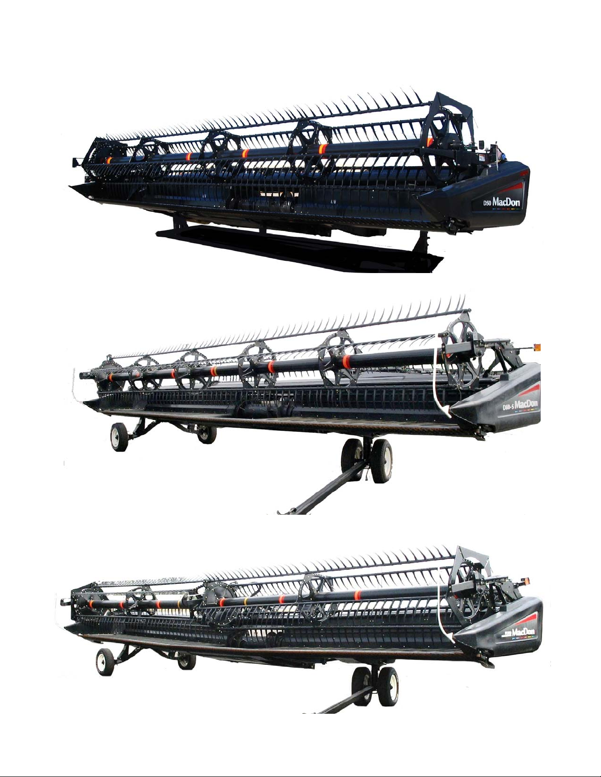
D50 HARVEST HEADER
D60 HARVEST HEADER
FD70 FLEXDRAPER
Page 3

1 INTRODUCTION
This instructional manual contains information on the D50/D6 0 Harvest Headers, FD70 FlexDraper, and the CA20
Combine Adapter. It must be used in conjunction with your Combine Operator's Manual.
The FD70 FlexDraper header is specially designed as a “straight cut” header, and is equipped to work well in all
straight cut conditions, whether cutting on or above the ground, utili zing a three piece flexible frame to clo sely follow
ground contours.
The CA20 Combine Adapter allows any of the D and FD Series headers to be easily attached to your specific
combine.
CAREFULLY READ ALL THE MATERIAL PROVIDED BEFORE ATTEMPTING TO UNLOAD, ASSEMBLE, OR
USE THE MACHINE.
Use this manual as your first source of information about the machine. If you follow the instructions given here, your
Header will work well for many years. If you require more detailed service information, a Service Manual is available
from your MacDon Dealer.
Use the Table of Contents and the Index to guide you to specific areas. Study the Table of Contents to familiarize
yourself with how the material is organized.
Keep this manual handy for frequent reference and to pass
on to new Operators or Owners.
A storage case for this manual is located inside the header
left endshield.
Call your MacDon Dealer if you need assistance,
information, or additional copies of this manual.
Published August, 2011
Form 169006 1 Revision D
Page 4
2 MODEL AND SERIAL NUMBER
NOTE: Right hand (RH) and Left-hand (LH) designations are determined from the Operator’s position, facing
forward.
Record the Model Number, Serial Number, and Model Year of the Header, Slow Speed Transpo rt/Stabilizer Wheel
Option (if installed), and the Combine Adapter on the lines below:
HEADER MODEL______________SERIAL NO._____________ ____YEAR_____
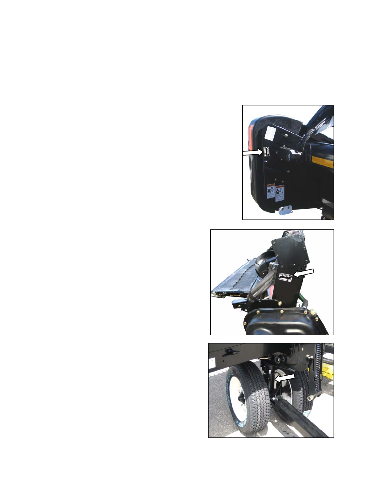
Serial Number Plate is located on the left hand endsheet, near the knife
drive motor.
ADAPTER MODEL________SERIAL NO.______________YEAR_____
Serial Number Plate is located on the frame above the main
drive gearbox.
SLOW SPEED TRANSPORT/STABILIZER WHEEL OPTION
SERIAL NO.__________________YEAR_____
Serial Number Plate is located on the left hand wheel pivot tube.
Form 169006 2 Revision D
Page 5

TABLE OF CONTENTS
Section/Title Page
1
INTRODUCTION ............................................................................................................................................. 1
2 MODEL AND SERIAL NUMBER .................................................................................................................... 2
3 SAFETY ........................................................................................................................................................... 7
3.1 SAFETY ALERT SYMBOL .................................................................................................................... 7
3.2 SIGNAL WORDS................................................................................................................................... 7
3.3 SAFETY DECALS ................................................................................................................................. 7
3.3.1 Safety Decal Installation ............................................................................................................... 7
3.3.2 Safety Decal Locations ................................................................................................................. 8
3.4 GENERAL SAFETY ............................................................................................................................ 20
4 DEFINITIONS ................................................................................................................................................ 22
5 COMPONENT IDENTIFICATION .................................................................................................................. 23
5.1 COMBINE HEADER ............................................................................................................................ 23
5.2 COMBINE ADAPTER .......................................................................................................................... 24
6 SPECIFICATIONS ......................................................................................................................................... 25
7 HEADER ATTACHMENT / DETACHMENT ................................................................................................ . 27
7.1 ADAPTER SET-UP ............................................................................................................................. 27
7.1.1 Center-Link Kit ............................................................................................................................ 27
7.1.2 Flighting Extensions .................................................................................................................... 28
7.1.3 Stripper Bars ............................................................................................................................... 28
7.1.4 CR Feeder Deflectors ................................................................................................................. 29
7.1.5 Auger Drive ................................................................................................................................. 29
7.2 CASE IH 7010, 8010, 7120, 8120, 5088, 6088, 7088 .......................................................................... 30
7.2.1 Attachment .................................................................................................................................. 30
7.2.2 Detachment ................................................................................................................................. 32
7.3 CASE IH 2300, 2500 SERIES ............................................................................................................. 34
7.3.1 Attachment .................................................................................................................................. 34
7.3.2 Detachment ................................................................................................................................. 37
7.4 JOHN DEERE 60, 70 SERIES ............................................................................................................. 40
7.4.1 Attachment .................................................................................................................................. 40
7.4.2 Detachment ................................................................................................................................. 42
7.5 JOHN DEERE 50 SERIES .................................................................................................................. 44
7.5.1 Attachment .................................................................................................................................. 44
7.5.2 Detachment ................................................................................................................................. 46
7.6 CAT LEXION 400, 500 SERIES .......................................................................................................... 48
7.6.1 Attachment .................................................................................................................................. 48
7.6.2 Detachment ................................................................................................................................. 51
7.7 NEW HOLLAND CR, CX ..................................................................................................................... 54
7.7.1 Attachment .................................................................................................................................. 54
7.7.2 Detachment ................................................................................................................................. 56
7.8 AGCO .................................................................................................................................................. 58
7.8.1 Attachment .................................................................................................................................. 58
7.8.2 Detachment ................................................................................................................................. 61
8 HEADER/ADAPTER DISASSEMBLY AND ASSEMBLY ............................................................................ 63
8.1 D50 AND D60 HARVEST HEADER/ADAPTER .................................................................................. 63
8.1.1 Disassembly ................................................................................................................................ 63
8.1.2 Assembly ..................................................................................................................................... 66
8.2 FD70 FLEXDRAPER/ADAPTER ......................................................................................................... 71
8.2.1 Disassembly ................................................................................................................................ 71
Form 169006 3 Revision D
Page 6

TABLE OF CONTENTS
8.2.2 Assembly ..................................................................................................................................... 75
9 OPERATION .................................................................................................................................................. 79
9.1 OWNER/OPERATOR RESPONSIBILITIES ........................................................................................ 79
9.2 OPERATIONAL SAFETY .................................................................................................................... 79
9.3 BREAK-IN PERIOD ............................................................................................................................. 80
9.4 PRE-SEASON CHECK ........................................................................................................................ 80
9.5 DAILY START-UP CHECK .................................................................................................................. 81
9.6 SHUTDOWN PROCEDURE ................................................................................................................ 81
9.7 HEADER CONTROLS ......................................................................................................................... 82
9.8 HEADER LIFT CYLINDER LOCK-OUTS............................................................................................. 82
9.9 REEL PROPS ...................................................................................................................................... 82
9.10 STORAGE ........................................................................................................................................... 84
9.11 HEADER SET-UP ................................................................................................................................ 85
9.11.1 Header Operating Variables ........................................................................................................ 89
9.11.2 Cutting Height .............................................................................................................................. 89
9.11.3 Header Float ................................................................................................................................ 92
9.11.4 Header Angle ............................................................................................................................... 96
9.11.5 Reel Speed .................................................................................................................................. 97
9.11.6 Ground Speed ............................................................................................................................. 98
9.11.7 Draper Speed .............................................................................................................................. 99
9.11.8 Knife Speed ............................................................................................................................... 100
9.11.9 Reel Height ................................................................................................................................ 100
9.11.10 Reel Fore-Aft Position ............................................................................................................... 101
9.11.11 Reel Tine Pitch .......................................................................................................................... 105
9.11.12 Crop Dividers and Rods ............................................................................................................ 107
9.12 DRAPER DEFLECTORS ................................................................................................................... 110
9.12.1 Deflector Replacement .............................................................................................................. 110
9.12.2 Deflector Rework ....................................................................................................................... 110
9.13 KNIFE HEAD SHIELD ....................................................................................................................... 111
9.14 HEADER LEVELLING ....................................................................................................................... 112
9.15 UNPLUGGING CUTTERBAR ............................................................................................................ 113
9.16 UNPLUGGING ADAPTER ................................................................................................................. 113
9.17 UPPER CROSS AUGER ................................................................................................................... 114
9.18 TRANSPORTING HEADER .............................................................................................................. 115
9.18.1 On the Combine ........................................................................................................................ 115
9.18.2 Towing ....................................................................................................................................... 115
9.18.3 Converting from Transport to Field Position .............................................................................. 116
9.18.4 Converting from Field to Transport Position .............................................................................. 121
9.19 WINDROWING .................................................................................................................................. 124
9.19.1 Adapter Modification .................................................................................................................. 124
10 MAINTENANCE AND SERVICING ......................................................................................................... 128
10.1 PREPARATION FOR SERVICING .................................................................................................... 128
10.2 RECOMMENDED SAFETY PROCEDURES .................................................................................... 128
10.3 MAINTENANCE SPECIFICATIONS .................................................................................................. 129
10.3.1 Recommended Torques ............................................................................................................ 129
10.3.2 Roller Chain Installation............................................................................................................. 132
10.3.3 Sealed Bearing Installation ........................................................................................................ 132
10.3.4 Recommended Fluids and Lubricants ....................................................................................... 133
10.3.5 Conversion Chart ....................................................................................................................... 134
10.4 ENDSHIELDS AND COVERS ........................................................................................................... 135
10.4.1 Endshields ................................................................................................................................. 135
10.4.2 Linkage Cover (FD70 FLEXDRAPER ONLY) ........................................................................... 138
Form 169006 4 Revision D
Page 7

TABLE OF CONTENTS
10.5
LUBRICATION .................................................................................................................................. 139
10.5.1 Greasing Procedure .................................................................................................................. 139
10.5.2 Lubrication Points ...................................................................................................................... 139
10.5.3 Oiling Requirements.................................................................................................................. 147
10.5.4 Auger Drive Chain Lubrication .................................................................................................. 148
10.5.5 Main Drive Gearbox Lubrication ............................................................................................... 148
10.6 HYDRAULICS ................................................................................................................................... 150
10.6.1 Reservoir ................................................................................................................................... 150
10.6.2 Hydraulic Oil Filter ..................................................................................................................... 152
10.6.3 Hoses and Lines ....................................................................................................................... 152
10.6.4 Hydraulic Schematics................................................................................................................ 153
10.7 ELECTRICAL .................................................................................................................................... 156
10.8 MAIN DRIVE ...................................................................................................................................... 156
10.8.1 Driveline Removal ..................................................................................................................... 156
10.8.2 Driveline Installation .................................................................................................................. 157
10.8.3 Guard Removal ......................................................................................................................... 157
10.8.4 Guard Installation ...................................................................................................................... 158
10.8.5 Drive Chain Adjustment ............................................................................................................ 159
10.9 AUGER .............................................................................................................................................. 160
10.9.1 Auger Pan Clearance ................................................................................................................ 160
10.9.2 Auger Drive Chain Adjustment .................................................................................................. 161
10.9.3 Auger Drive Chain Replacement .............................................................................................. 162
10.9.4 Auger Tine Replacement .......................................................................................................... 163
10.10 VIBRATION DAMPERS .................................................................................................................... 165
10.10.1 Rubber Pad Replacement ......................................................................................................... 165
10.11 SICKLE AND SICKLE DRIVE ............................................................................................................ 166
10.11.1 Sickle Sections .......................................................................................................................... 166
10.11.2 Sickle Removal ......................................................................................................................... 167
10.11.3 Sickle Head Bearing Replacement ........................................................................................... 167
10.11.4 Sickle Installation ...................................................................................................................... 168
10.11.5 Spare Sickle (Single Knife Headers) ......................................................................................... 168
10.11.6 Sickle Guards ............................................................................................................................ 169
10.11.7 Sickle Hold-Downs .................................................................................................................... 172
10.11.8 Sickle Drive Belts: Non-Timed Drive ......................................................................................... 173
10.11.9 Double Knife Drive Belts: Timed Drive ...................................................................................... 174
10.11.10 Wobble Box ............................................................................................................................... 179
10.12 ADAPTER FEED DRAPER ............................................................................................................... 182
10.12.1 Draper Tension Adjustment ...................................................................................................... 182
10.12.2 Replacing Draper ...................................................................................................................... 182
10.13 HEADER DRAPERS ......................................................................................................................... 184
10.13.1 Header Draper Tension Adjustment ......................................................................................... 184
10.13.2 Replacing Split Draper .............................................................................................................. 184
10.13.3 Header Draper Alignment ......................................................................................................... 186
10.13.4 Draper Roller Maintenance ....................................................................................................... 187
10.13.5 Deck Height ............................................................................................................................... 190
10.14 REEL AND REEL DRIVE .................................................................................................................. 191
10.14.1 Reel Clearance to Cutterbar: D50, D60 .................................................................................... 191
10.14.2 Reel Clearance to Cutterbar: FD70 .......................................................................................... 192
10.14.3 Reel Frown Adjustment ............................................................................................................. 194
10.14.4 Reel Centering .......................................................................................................................... 194
10.14.5 Reel Drive Chain: D60, FD70 ................................................................................................... 195
10.14.6 Reel Drive Chain: D50 .............................................................................................................. 199
10.14.7 Reel Drive Sprocket: D60, FD70 ............................................................................................... 200
10.14.8 Reel Drive Sprocket: D50 ......................................................................................................... 201
10.14.9 Reel Drive U-Joint: D60, FD70 ONLY ....................................................................................... 202
Form 169006 5 Revision D
Page 8

TABLE OF CONTENTS
10.14.10 Reel Drive Motor: D60, FD70 .................................................................................................... 203
10.14.11 Reel Drive Motor: D50 ............................................................................................................... 204
10.14.12 Reel Speed Sensor ............................................................................................................. ...... 205
10.14.13 Reel Tines ................................................................................................................................. 208
10.14.14 Tine Tube Bushings ................................................................................................................... 210
10.15 HEADER WING FLOAT ..................................................................................................................... 214
10.15.1 Wing Float Lock Adjustment ...................................................................................................... 214
10.15.2 Wing Balance ............................................................................................................................ 214
10.15.3 Wing Linkage Adjustment .......................................................................................................... 216
10.16 TRANSPORT SYSTEM ..................................................................................................................... 217
10.16.1 Wheel Bolt Torque ..................................................................................................................... 217
10.16.2 Axle Bolts ................................................................................................................................... 217
10.16.3 Tire Inflation ............................................................................................................................... 217
10.17 MAINTENANCE SCHEDULE ............................................................................................................ 218
10.17.1 Break-In Inspections .................................................................................................................. 218
10.17.2 Interval Maintenance ................................................................................................................. 219
10.17.3 Maintenance Record ................................................................................................................. 220
11 TROUBLESHOOTING ............................................................................................................................. 222
11.1 CROP LOSS AT CUTTERBAR .......................................................................................................... 222
11.2 CUTTING ACTION AND SICKLE COMPONENTS ........................................................................... 223
11.3 REEL DELIVERY ............................................................................................................................... 225
11.4 HEADER AND DRAPERS ................................................................................................................. 227
11.5 FD70 FLEXDRAPER ......................................................................................................................... 229
11.6 CUTTING EDIBLE BEANS ................................................................................................................ 230
12 OPTIONS AND ATTACHMENTS ............................................................................................................ 234
12.1 AUTO HEADER HEIGHT CONTROLLER ......................................................................................... 234
12.2 KNIFE REVERSING KIT .................................................................................................................... 234
12.3 FLOAT/ANGLE INDICATOR ............................................................................................................. 234
12.4 HYDRAULIC HEADER TILT .............................................................................................................. 234
12.5 CUTTERBAR POLY .......................................................................................................................... 235
12.6 ADJUSTABLE SKID SHOES WITH POLY COVER ........................................................................... 235
12.7 STUB GUARD CONVERSION KIT .................................................................................................... 235
12.8 STABILIZER WHEELS ...................................................................................................................... 235
12.9 STABILIZER/TRANSPORT WHEELS ............................................................................................... 235
12.10 LODGED CROP REEL FINGER KIT ................................................................................................. 236
12.11 VERTICAL KNIFE MOUNTS ............................................................................................................. 236
12.12 UPPER CROSS AUGER ................................................................................................................... 236
12.13 REEL ENDSHIELD KIT ..................................................................................................................... 236
12.14 ROCK RETARDER KIT ..................................................................................................................... 237
12.15 RICE DIVIDER KIT ............................................................................................................................ 237
12.16 HYDRAULIC REEL FORE-AFT POSITIONER .................................................................................. 237
12.17 CA20 DELICATE SEED SAVER KIT ................................................................................................. 237
12.18 KNIFE HEAD SHIELD ....................................................................................................................... 237
13 UNLOADING AND ASSEMBLY .............................................................................................................. 238
INDEX …………………………………………………………………………………….……………....………………...239
Form 169006 6 Revision D
Page 9
SECTION 3. SAFETY
3 SAFETY
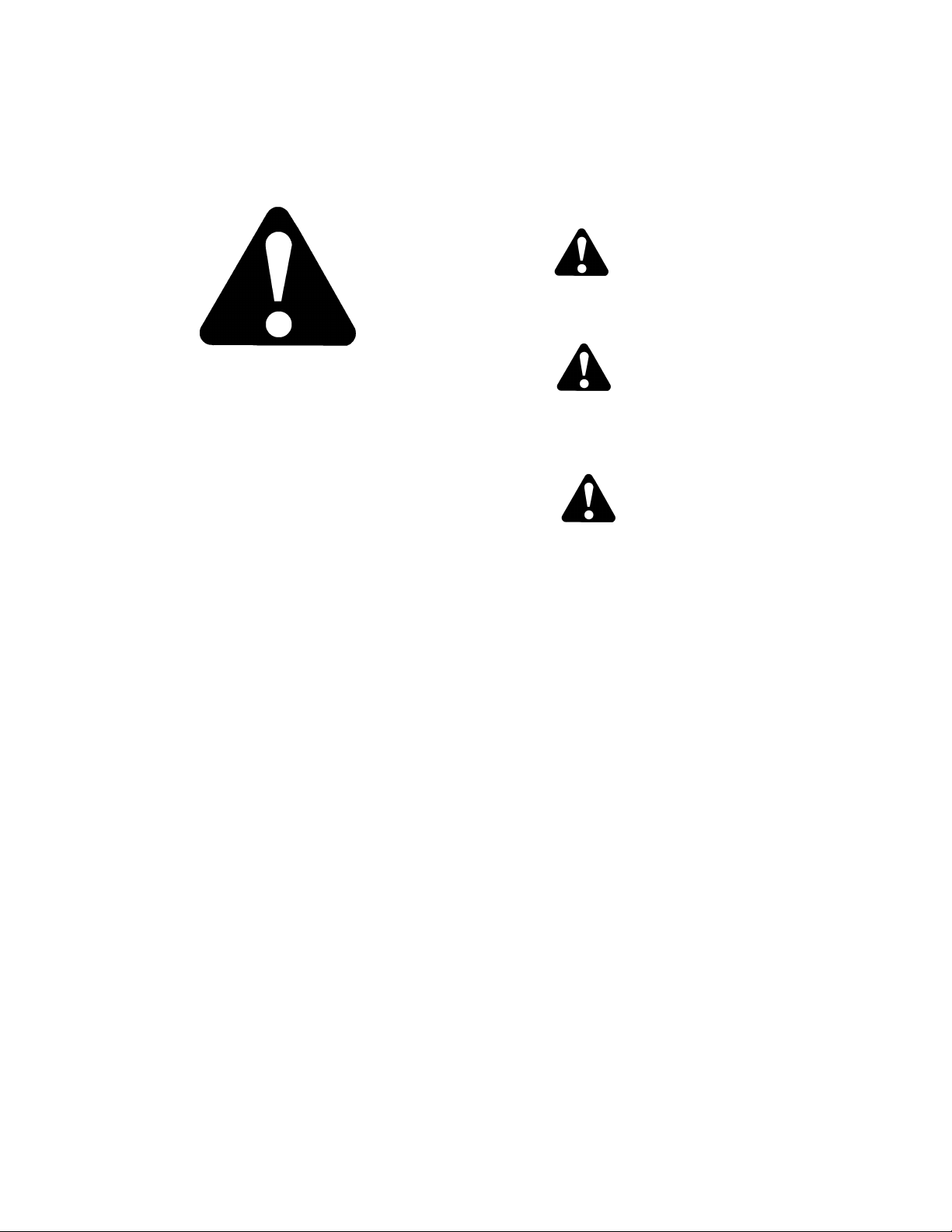
3.1 SAFETY ALERT SYMBOL
This safety alert symbol indicates important safety
messages in this manual and on safety decals on the
machine.
This symbol means:
ATTENTION!
BECOME ALERT!
YOUR SAFETY IS INVOLVED!
Carefully read and follow the safety message
accompanying this symbol.
WHY IS SAFETY IMPORTANT TO YOU?
ACCIDENTS DISABLE AND KILL.
ACCIDENTS COST.
ACCIDENTS CAN BE AVOIDED.
3.2 SIGNAL WORDS
Note the use of the signal words DANGER,
WARNING, and CAUTION with safety messages.
The appropriate signal word for each message has
been selected using the following guidelines:
DANGER
Indicates an imminently hazardous situation
that, if not avoided, will result in death or
serious injury.
WARNING
Indicates a potentially hazardous situation
that, if not avoided, could result in death or
serious injury. It is also used to alert against
unsafe practices.
CAUTION
Indicates a potentially hazardous situation
that, if not avoided, may result in minor or
moderate injury. It is also used as a reminder
of good safety practices.
3.3 SAFETY DECALS
The safety decals appear on the header at
the locations shown on pages 8 to 19.
Keep safety decals clean and legible at all
times.
Replace safety decals that are missing or
become illegible.
If original parts on which a safety decal was
installed are replaced, be sure the repair part
also bears the current safety decal.
Safety decals are available from your
MacDon Dealer Parts Department.
3.3.1 Safety Decal Installation
a. Be sure the installation area is clean and dry.
b. Decide on the exact location before you remove
the decal backing paper.
c. Remove the smaller portion of the split backing
paper.
d. Place the decal in position and slowly peel back
the remaining paper, smoothing the decal as it is
applied.
e. Small air pockets can be smoothed out or pricked
with a pin.
Form 169006 7 Revision D
Page 10

SECTION 3. SAFETY
3.3.2 Safety Decal Locations
3.3.2.1 3-Panel Safety Decals: North America
BACK TUBE #134070
BACK TUBE - BOTH ENDS
#172147
FD70
BACK TUBE #42122
D60 45 FT
BACK TUBE #134070
Form 169006 8 Revision D
Page 11

SECTION 3. SAFETY
A
3-Panel Safety Decals: North America (Cont’d)
BACK TUBE #109843
BACK TUBE #134070
D60 20 FT
BACK TUBE & DECKS #172147
LL
Form 169006 9 Revision D
Page 12

SECTION 3. SAFETY
3-Panel Safety Decals: North America (Cont’d)
BACK TUBE #134070
D50, D60: 30, 35, 40 FT D60 25 FT
BACK TUBE BOTH ENDS
BACK TUBE - DOUBLE REEL ONLY
#172147
#42122
Form 169006 10 Revision D
Page 13

SECTION 3. SAFETY
3-Panel Safety Decals: North America (Cont’d)
ALL
BOTH ENDS - DOUBLE KNIFE
LEFT END - SINGLE KNIFE
#142909
LH & RH REEL ARMS
#174633
LH & RH REEL ARMS
#42122
REEL ARMS
#174633
D60, FD70
D50
D50
Form 169006 11 Revision D
Page 14

SECTION 3. SAFETY
3-Panel Safety Decals: North America (Cont’d)
DRIVELINE
#30316
INSIDE DRIVELINE GUARD
#36651
Form 169006 12 Revision D
Page 15
SECTION 3. SAFETY
3.3.2.2 2-Panel Safety Decals: North America
and Export
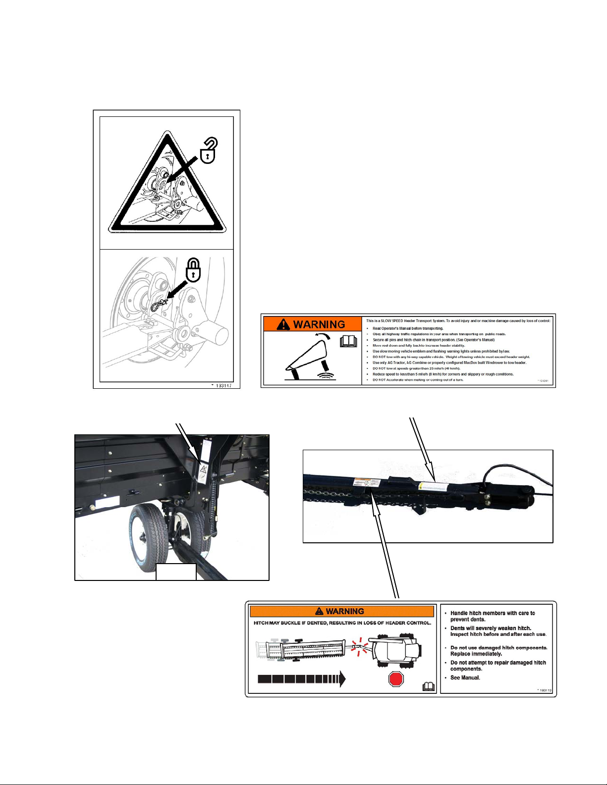
FRONT TRANSPORT LEG
#193147
TOW-BAR
#129261
TOW-BAR
#193113
Form 169006 13 Revision D
Page 16
SECTION 3. SAFETY
2-Panel Safety Decals: North America and Export
(Cont’d)
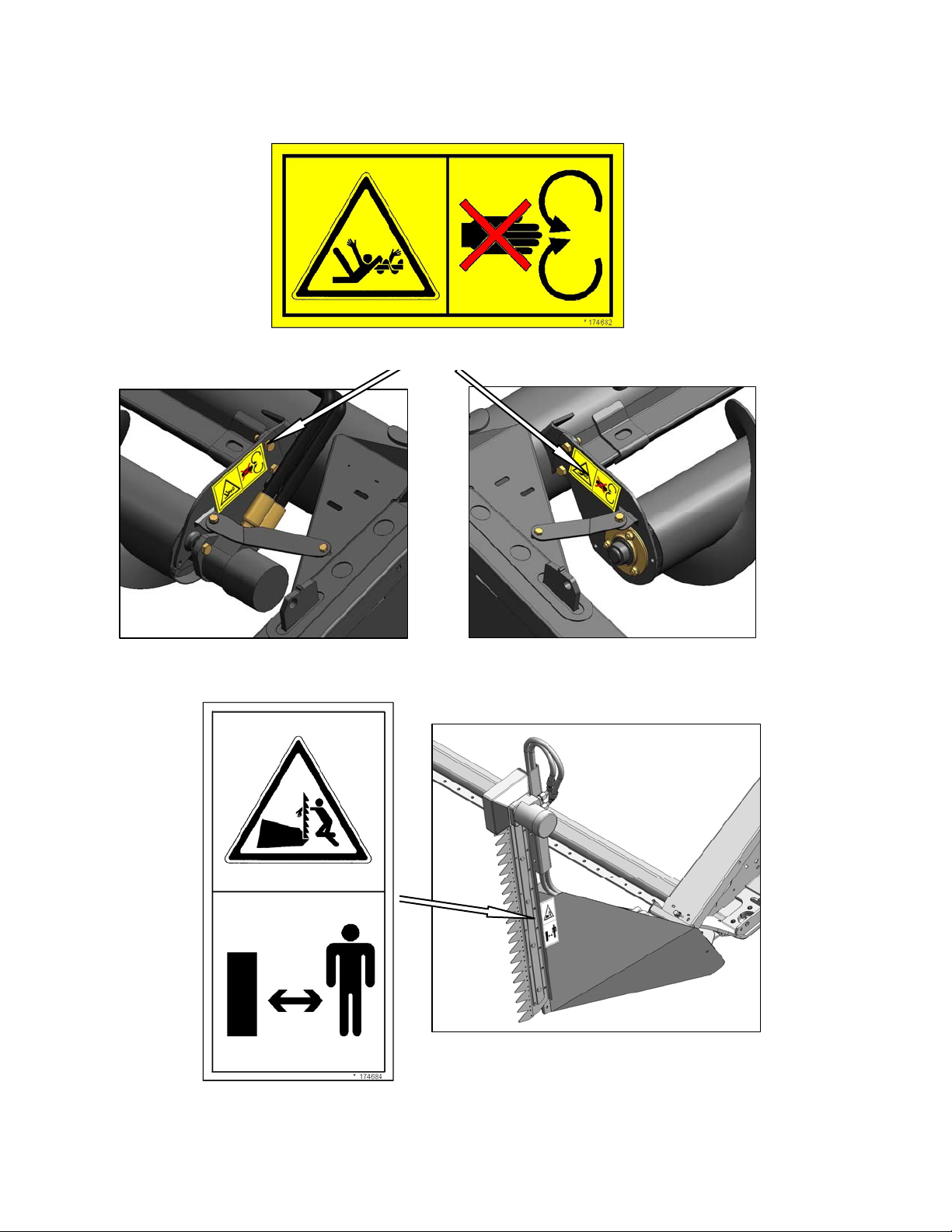
UPPER CROSS AUGER
#174682
LH AND RH
VERTICAL KNIFE
#174684
Form 169006 14 Revision D
Page 17
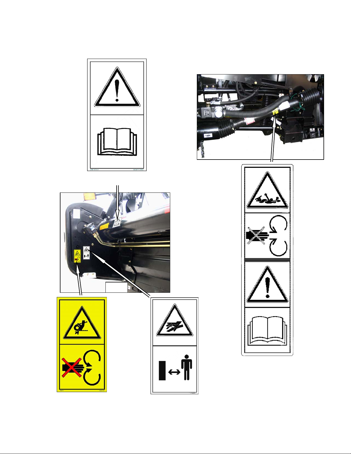
3.3.2.3 2-Panel Safety Decals: Export
BOTH ENDS #113482
SECTION 3. SAFETY
ALL
DRIVELINE
#194521
BOTH ENDS - DOUBLE KNIFE
LEFT END - SINGLE KNIFE
#184371
Form 169006 15 Revision D
BOTH ENDS #174436
Page 18

SECTION 3. SAFETY
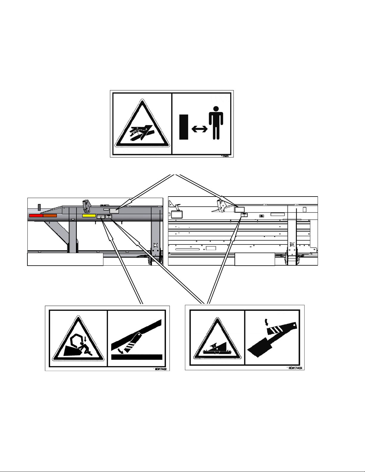
2-Panel Safety Decals: Export (Cont’d)
BACKTUBE #174474
FD70
BACKTUBE - BOTH ENDS #174434
BACKTUBE #174474
BACKTUBE #174432
Form 169006 16 Revision D
Page 19

2-Panel Safety Decals: Export (Cont’d)
BOTH ENDS #113482
SECTION 3. SAFETY
BACKTUBE #174474
D60 20 FT
BACKTUBE AND DECKS #174434
ALL
Form 169006 17 Revision D
Page 20
2-Panel Safety Decals: Export (Cont’d)
SECTION 3. SAFETY
BACK TUBE - BOTH ENDS
D50, D60: 30, 35, 40 FT D60 25 FT
BACK TUBE - DOUBLE REEL ONLY
#174432
BACK TUBE - BOTH ENDS
#174434
Form 169006 18 Revision D
Page 21
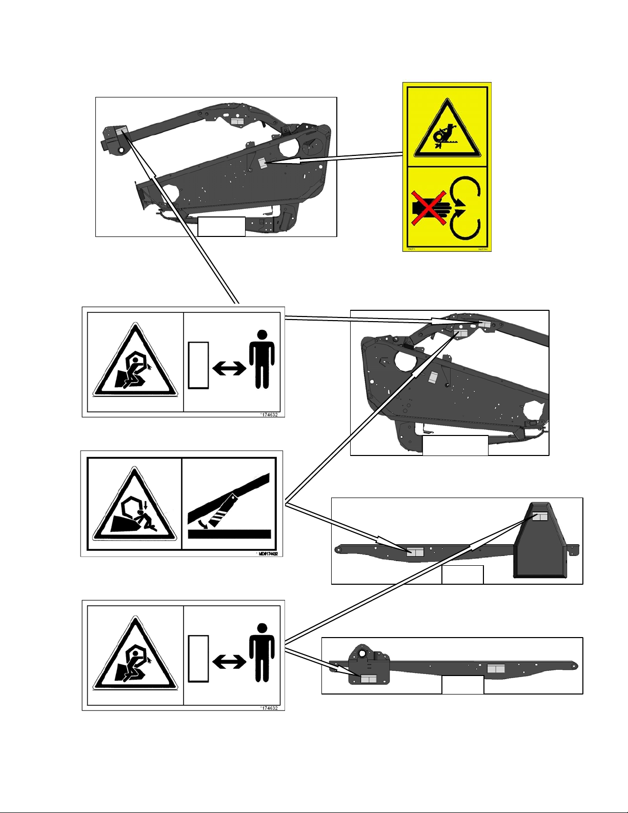
2-Panel Safety Decals: Export (Cont’d)
ALL
SECTION 3. SAFETY
BOTH ENDS - DOUBLE KNIFE
LEFT END - SINGLE KNIFE
#184371
REEL ARMS
#174632
LH & RH REEL ARM
#174432
REEL ARMS
#174632
D60, FD70
D50
D50
Form 169006 19 Revision D
Page 22
SECTION 3. SAFETY
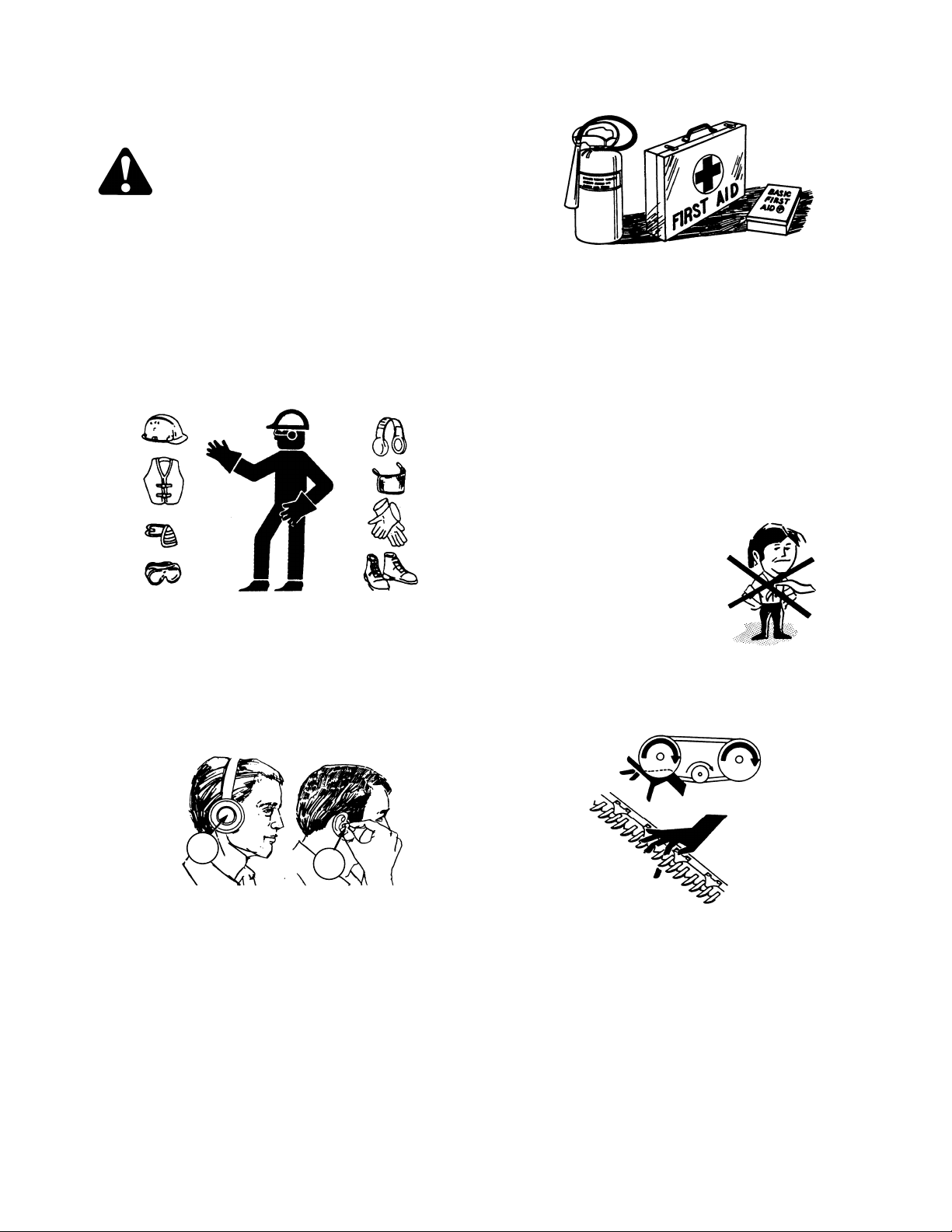
3.4 GENERAL SAFETY
CAUTION
The following are general farm safety
precautions that should be part of your
operating procedure for all types of
machinery.
Protect yourself. When assembling,
operating and servicing machinery, wear
all the protective clothing and personal
safety devices that COULD be necessary
for the job at hand. Don't take chances.
You may need:
a hard hat.
protective shoes with slip resistant
soles.
protective glasses or goggles.
heavy gloves.
wet weather gear.
respirator or filter mask.
Provide a first-aid kit for use in case of
emergencies.
Keep a fire extinguisher on the machine.
Be sure the extinguisher is properly
maintained and be familiar with its proper
use.
Keep young children away from
machinery at all times.
Be aware that accidents often happen
when the Operator is tired or in a hurry to
get finished. Take the time to consider th e
safest way. Never ignore warning signs of
fatigue.
Wear close-fitting
clothing and cover
long hair. Never wear
dangling items such
as scarves or
bracelets.
Keep hands, feet,
clothing and hair
away from moving parts. Never attempt to
clear obstructions or objects from a
machine while the engine is running.
A
hearing protection. Be aware that
prolonged exposure to loud noise
can cause impairment or loss of
hearing. Wearing a suitable hearing
protective device such as ear muffs
(A) or ear plugs (B) protects against
objectionable or loud noises.
Form 169006 20 Revision D
B
Keep all shields in place. Never alter or
remove safety equipment. Make sure
driveline guards can rotate independently
of the shaft and can telescope freely.
Page 23

SECTION 3. SAFETY
Use only service and repair parts made or
approved by the equipment manufact urer.
Substituted parts may not meet strength,
design, or safety requirements.
Do not modify the machine. Unauthorized
modifications may impair the function
and/or safety and affect machine life.
Stop engine, and remove key from
ignition before leaving Operator's seat for
any reason. A child or even a pet could
engage an idling machine.
Keep the area used for servicing
machinery clean and dry. Wet or oily
floors are slippery. Wet spots can be
dangerous when working with electrical
equipment. Be sure all electrical outlets
and tools are properly grounded.
Use adequate light for the job at hand.
Keep machinery clean. Straw and chaff on
a hot engine are a fire hazard. Do not
allow oil or grease to accumulate on
service platforms, ladders or controls.
Clean machines before storage.
Never use gasoline, naphtha or any
volatile material for cleaning purposes.
These materials may be toxic and/or
flammable.
When storing machinery, cover sharp or
extending components to prevent injury
from accidental contact.
Form 169006 21 Revision D
Page 24

SECTION 4. DEFINITIONS
4 DEFINITIONS
The following terms/abbreviations may be used in this manual:
TERM DEFINITION
API
ASTM
Center-link
DK
GSL
Header
rpm
SAE
SK
spm
Tractor
Truck
American Petroleum Institute
American Society Of Testing and Materials
A hydraulic cylinder or turnbuckle type link between the header and the
machine that tilts the header.
Double Knife
Ground Speed Lever
A machine that cuts and lays crop into a windrow, and is attached to a
self-propelled windrower or combine.
Revolutions per minute
Society Of Automotive Engineers
Single Knife
Strokes per minute
Ag type tractor.
A four-wheel highway/road vehicle weighing no less than
7500 lb (3400 kg).
Form 169006 22 Revision D
Page 25
SECTION 5. COMPONENT IDENTIFICATION
(
)
5 COMPONENT IDENTIFICATION
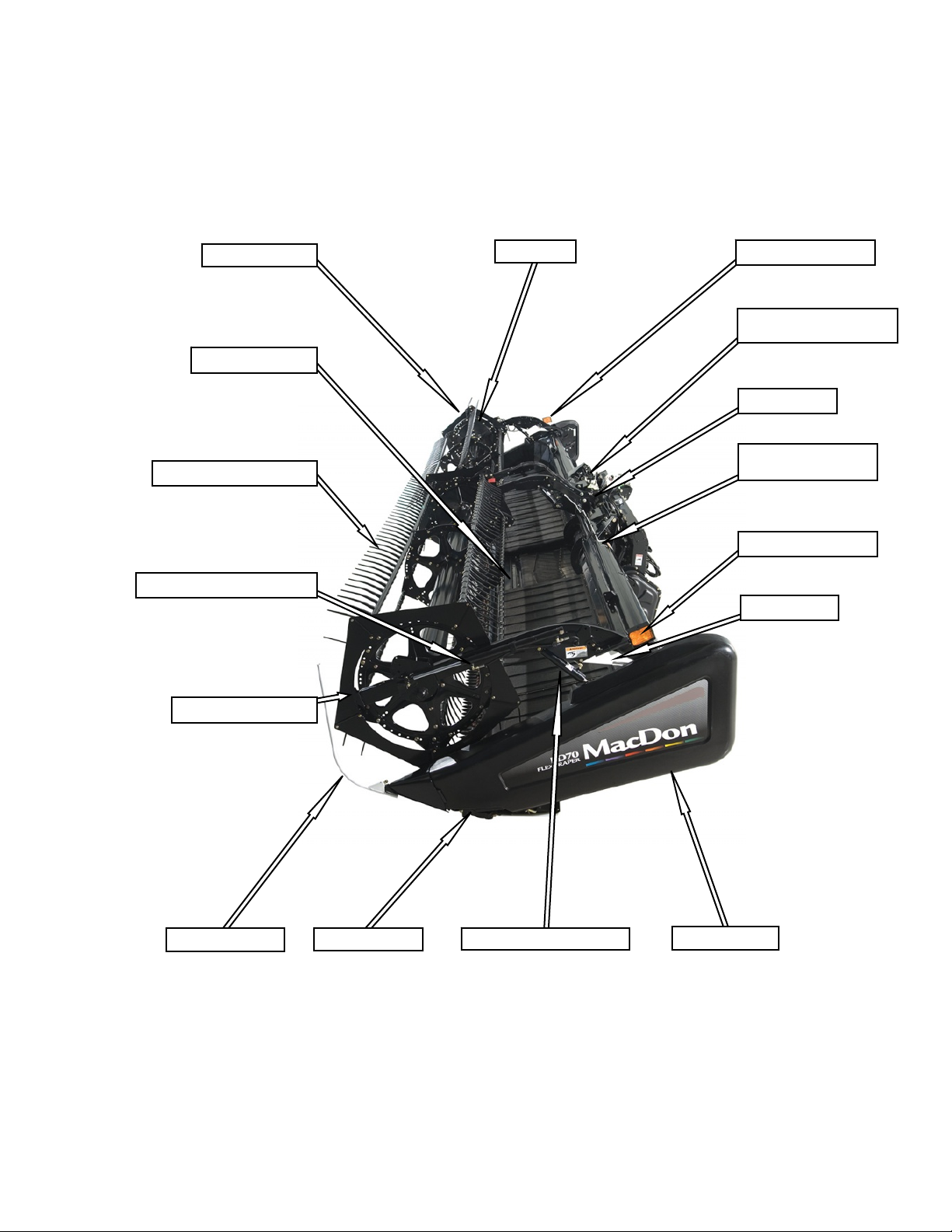
5.1 COMBINE HEADER
PICK-UP REEL
TRANSITION PAN
PICK-UP REEL FINGERS
REEL FORE-AFT CYLINDER
REEL CAM
TRANSPORT LIGHT
WING FLOAT LINKAGE
FD70 ONLY
CENTER-LINK
CENTER REEL ARM
PROP HANDLE
TRANSPORT LIGHT
REEL PROP
REEL ENDSHIELDS
CROP DIVIDER
WOBBLE BOX
REEL LIFT CYLINDER
ENDSHIELD
Form 169006 23 Revision D
Page 26
SECTION 5. COMPONENT IDENTIFICATION
(
)
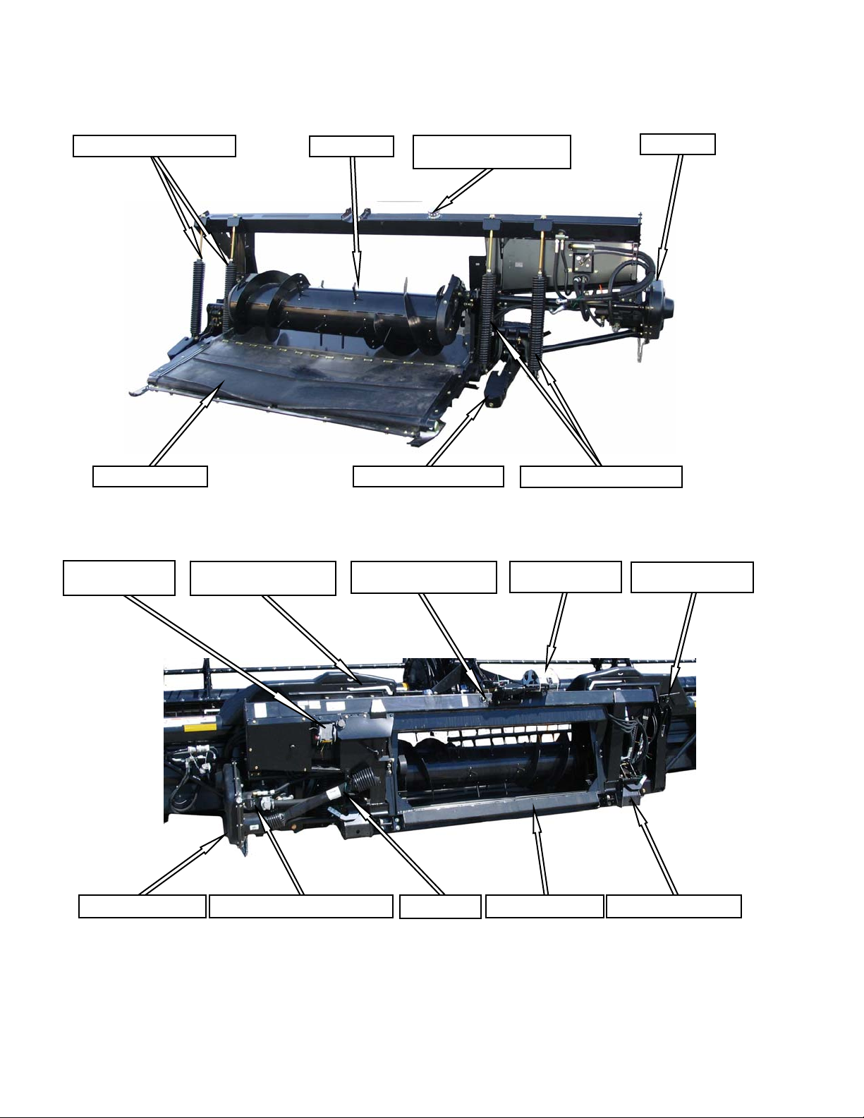
5.2 COMBINE ADAPTER
HEADER FLOAT SPRINGS
AUGER
HYDRAULIC RESERVOIR
FILLER PIPE CAP
VIBRATION DAMPENER FEED DRAPER
HEADER FLOAT SPRINGS
GEARBOX
HYDRAULICS
MULTI-COUPLER
ADAPTER GEARBOX
WING FLOAT INDICATOR
(FD70 ONLY)
RESERVOIR OIL LEVEL
SIGHT GLASS
DRIVELINE DRAPER / KNIFE DRIVE PUMP
AUTO HEADER
HEIGHT CONTROL
TRANSITION FRAME
WING FLOAT LOCK
FD70 ONLY
HEADER FLOAT LOCK
Form 169006 24 Revision D
Page 27

6 SPECIFICATIONS
HEADER MODEL
HEADER SIZE 20 FT 25 FT 30 FT 35 FT 40 FT 45 FT
OVERALL
Width
(Inches (mm))
Length
(Inches (mm))
Height -Transport
Estimated Weight Range
Base Header - No Adapter
(lb (kg))
CUTTERBAR
Width (Inches (mm)
Header Cutting Height
Guard Angle (Cutterbar on Ground)
SICKLE
Drive Type
Sickle Speed
Stroke
Sections - Over-Serrated
& Bolted (serrations/inch)
Guards and
Hold-Downs
Transport (Reel Full
Aft) With CA20 Adapter
Field
Transport
(with Tow
Pole)
D50, D60
FD70
D50
D60
FD70
Shortest Center-Link
Longest Center-Link
DK (Except D50)
Cut-Out or Solid
D50
Pointed
D60
FD70
Stub (Except D50)
SECTION 6. SPECIFICATIONS
D60 D50 / D60 D50 / D60 / FD70 D60 / FD70 D60 / FD70
96 (2438)
255.1 (6479) 315.1 (8003) 375.1 (9527) 435.1 (11051) 495.1 (12575) 555.1 (14099)
Not Applicable 505.7 (12845) 547.5 (139 07 )
Not Applicable 513.0 (13029) 556.7 (141 41 )
97 in. (2464 mm)
Not Applicable 3500 (1589) 4150 (1884) 4700 (2134) Not Applicable
3400 (1544)
Not Applicable 4850 (2202) 5250 (2384)
240 (6096) 300 (7620) 360 (9144) 420 (10668) 480 (12192) 540 (13716)
1.3 in. (32 mm) below ground -
52.3 in. (1328 mm) above
4.6 in. (117 mm) below ground
- 46.9 in. (1192 mm) above
SK
Hydraulic Motor / Two ‘B’ Timing Belts / Two Heavy Duty (MD)
3500 - 4100
(1589 - 1861)
7.0° - 12.4° 2.0° - 7.4°
Hydraulic Motor / ‘C’ Belt/Heavy Duty (MD) Wobble Box
Wobble Boxes
SK
DK
14 9 / 14 9
Not Applicable Pointed / Case Hardened / Sheet Metal / Adjuster Bolt Not Applicable
Case Hardened or Double Heat Treated / Sheet Metal / Adjuster Bolt
Not Applicable Double Heat Treated / Sheet Metal / Adjuster Bolt
Sheet Metal
HD
Sheet Metal or
Forged HD
4200 - 5100
(1907 - 2315)
0.8 in. (20 mm) below ground - 52.8 in. (1340 mm) above
4.1 in. (105 mm) below ground - 47.4 in. (1204 mm) above
1200 Strokes Per Minute Not Applicable
1380 Strokes Per Minute
4700 - 5700
(2134 - 2588)
3 in. (76 mm)
601.5 (15278) 631.5 (16040)
5400 - 5800
(2451 - 2633)
5700 - 5900
(2588 - 2979)
Two Hydraulic Motors To "C"
Belts, Untimed To Heavy Duty
(MD) Wobble Boxes.
Not Applicable
6200 (2815)
6300 (2860)
CONVEYOR AND DECKS
Draper Drive
Draper Width
Draper Speed
Delivery Opening
Draper Angle
(Cutterbar on Ground)
Width
D50
D60
FD70
Height
D50, D60
FD70
247 - 464 ft/min (75 - 141 m/min)
Not Applicable 73.6 in. (1870 mm) Not Applicable
Not Applicable 73.6 in. (1870 mm)
37.2 - 41.7 in. (945 - 1058 mm)
Not Applicable 14.0° - 19.4°
Hydraulic
41.6 in. (1057 mm)
73.6 in. (1870 mm)
13.0° - 18.4°
Form 169006 25 Revision D
Page 28

SECTION 6. SPECIFICATIONS
HEADER MODEL
HEADER SIZE 20 FT 25 FT 30 FT 35 FT 40 FT 45 FT
REEL
Drive
Speed
Quantity of Tine Tubes
Effective Reel Diameter
Finger Tip Radius Range
Finger Type
Heavy Duty Plastic
Plastic
Finger Spacing
UPPER CROSS AUGER
Outside Diameter
Weight (lb (kg))
STABILIZER WHEELS
Size
Pressure
Weight
COMBINE ADAPTER
Width
Length
Height
Weight
Main Drive
Gearbox Capacity
Drive
Auger
Type
Speed
Drive
Feed Draper
Type
Width
Speed
Reservoir Capacity
Maximum Operating Pressure
Filter
Header Draper Drive Pump
Sickle Drive Pump
Adapter Header Flotation
Header Angle Control
Combine Requirement
NOTES: 1. Specifications and design are subject to change without notice or obligation to revise previously sold units.
2. Weights do not include options.
D60 D50 / D60 D50 / D60 / FD70 D60 / FD70 D60 / FD70
Hydraulic From Combine Hydraulic Oil Supply
0 - 67 rpm
6 / 9 5 / 6 / 9 5 / 6 5
65 in. (1650 mm)
30.2 - 31.5 in. (766 - 800 mm)
--- Standard
Std. Optional D60 & 30 FT FD70 Opt. D60 DK ---
6.0 in. (152.4 mm)
12 in. (305 mm)
163 (74) 192 (87) 221 (100) 250 (113) 279 (127) 308 (140)
ST205 / 75R-15
Not Applicable
151 inches (3835 mm)
70 inches (1778 mm)
50 inches (1270 mm)
Combine Driven Piston Pump and Gear Pump Through Gearbox
Auger - 14 inches (356 mm) with
4 inch (102 mm) Flighting
150 rpm (Combine Dependent)
Hydraulic Motor from Combine Driven Pump
Self-Tracking Rubber Coated Polyester Fabric With Rubber Slats
78.7 inches (2000 mm)
350 - 400 ft / min (107 - 122 meters / min)
16 U.S. gal (60 liters)
3500 psi (24132 kPa) Piston Pump, 3700 psi (25510 kPa) Gear Pump
10 micron #151975
1.01 in.3 (16.5 cc) Gear Pump
1.8 - 2.7 in.3 (29.5 - 44.2 cc) Piston Pump
7 - 8 Inches (178 - 203 mm) Vertical, 4 Degrees Rotation
Hydraulic From Combine Hydraulic Oil Supply
(With Solenoid Valve To Toggle To Reel Fore-aft / Header Tilt)
Load Range E - 80 psi (552 kPa)
Load Range D - 65 psi (448 kPa)
200 lb (91 kg)
2050 lb (930 kg)
5 Pints (2.5 liters)
Chain
Mechanical or
Class 5 or Higher
Form 169006 26 Revision D
Page 29

SECTION 7. HEADER ATTACHMENT / DETACHMENT
7 HEADER ATTACHMENT /
DETACHMENT
The header/adapter is configured to each
particular model of combine at the factory.
These combines are:
COMBINE SECTION
7.1.1 Center-Link Kit
Some combine models require shorter center-link
components to ensure clearance to the combine
cab.
Case IH 7010, 8010, 7120,
8120, 5088, 6088, 7088
Case IH 2300, 2500 Series 7.3
John Deere 60, 70 Series 7.4
John Deere 50 Series 7.5
CAT Lexion 400, 500
(R Series)
New Holland CR, CX 7.7
AGCO Gleaner R, A Series
Challenger 660, 670, 680B
Massey 9690, 9790, 9895
This section includes instructions on setting up,
attaching, and detaching the header to the
combines listed above.
IMPORTANT
Ensure applicable functions (AHHC,
Draper Header Option, Hydraulic
Center-Link Option, Hydraulic Reel
Drive, etc.) are enabled on the combine
and in the combine computer. Failure
to do so may result in improper header
operation.
7.2
7.6
7.8
SHORT CENTER-LINK ASSEMBLIES
NORMAL CENTER-LINK ASSEMBLIES
To avoid damage to your combine, lift feeder
slowly and check clearance between cab and
header center-link.
If clearance is inadequate, contact your MacDon
Dealer to order short center-link components.
Installation instructions are included.
7.1 ADAPTER SET-UP
The following sections outline recommended
adapter set-up guidelines, depending on your
combine and crop.
The recommendations cannot cover all
conditions.
If feeding problems develop with adapter
operation, refer to Section 11
TROUBLESHOOTING for detailed information.
Form 169006 27 Revision D
The following combine models have been
identified for requiring the SHORT center-link
components:
Case IH 5088, 6088, and 7088 without
Stone Traps.
Gleaner R Series.
Page 30
SECTION 7. HEADER ATTACHMENT / DETACHMENT
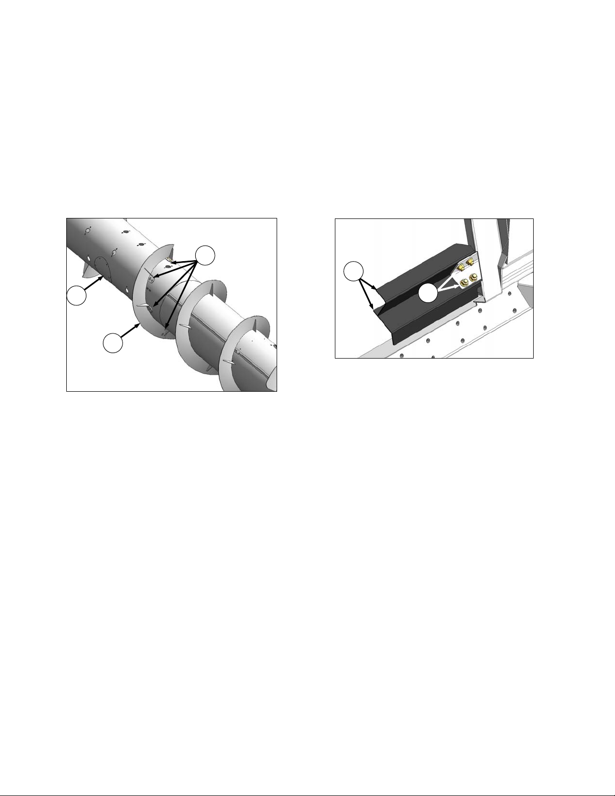
7.1.2 Flighting Extensions
Flighting extension kits may have been supplied
with your header to improve feeding in certain
crops such as rice. Installation instructions are
included with the kits.
They are not recommended in cereal crops.
APPLICABLE COMBINES: All except New
Holland CR960, 9060, 970, 9070, and 9080.
If necessary, remove auger flighting extensions
as follows:
B
A
C
7.1.3 Stripper Bars
Stripper bar kits may have been supplied with
your header to improve feeding in certain crops
such as rice. Installation instructions are included
with the kits.
They are not recommended in cereal crops.
APPLICABLE COMBINES: All except New
Holland CR960, 9060, 970, 9070, and 9080.
If necessary, remove auger stripper bars as
follows:
E
D
a. Remove access cover (A).
b. Remove eight bolts (B), washers, and nuts that
secure flighting extension (C) to auger and
remove extension.
c. Repeat for other flighting extension.
d. Re-install access cover (A).
a. Remove f our bolts (D) and nuts securing bars (E)
to adapter frame and remove bars.
b. Repeat for opposite set of stripper bars.
Form 169006 28 Revision D
Page 31

SECTION 7. HEADER ATTACHMENT / DETACHMENT
7.1.4 CR Feeder Deflectors
For New Holland CR 960, 9070, and 9080
combines, feeder kits have been installed on the
adapter at the factory to improve feeding into the
feeder house.
They may also have been installed as an option
on older machines. If necessary, they can be
removed.
CA20 adapters for the CR Models listed have
short feeder kits installed at the factory. Long
feeder kits are provided for narrow feeder house
combines, and are dealer-installed to replace the
short feeder kits.
COMBINE
MODEL
CR970, 9070,
9080
CR960, 9060,
940, 9040
FEEDER
HOUSE SIZE
Wide Short - 200 mm
Narrow Long - 325 mm
FEEDER KIT
SIZE
If required, replace the feeder deflectors as
follows:
A
B
LH SHOWN - RH OPPOSITE
b. Remove two bolts (B), and nuts securing
deflector (A) to adapter frame and remove
deflector.
c. Position replacement deflector, and secure with
bolts (B) and nuts. Maintain dimension “X” from
existing deflector for replacement deflector.
d. Repeat for opposite deflector.
e. After attaching header to combine, extend
center-link fully, and check gap “X” between
deflector and pan.
Maintain 7/8 in. (22 mm) +/- 1/8 in. (3 mm).
A
a. Determine position of existing deflector (A) by
measuring gap “X” between deflector forward
edge and pan.
7.1.5 Auger Drive
The adapter auger is chain driven from a sprocket
that is mounted on the input shaft from the
combine, and which is enclosed in the drive
gearbox.
The speed is determined by the combine input
shaft, and is matched to each particular combine,
so no adjustment is necessary.
However, optional drive sprockets are avai lable to
change the auger speed to optimize auger
performance. See your MacDon Dealer.
NOTE
For special conditions, 20T, 22T, and
26T sprockets are available to change
adapter feed auger speed. Consult with
your MacDon Dealer.
Form 169006 29 Revision D
Page 32

SECTION 7.2 CASE IH 7010, 8010, 7120, 8120, 88 SERIES
7.2 CASE IH 7010, 8010, 7120, 8120,
5088, 6088, 7088
7.2.1 Attachment
IMPORTANT
Some combine models require special
center-link components to ensure
clearance to the combine cab.
To avoid damage to your combine, lift
feeder slowly and check clearance
between cab and header center-link.
If clearance is inadequate, contact your
MacDon Dealer to order special centerlink components. Refer to Section 7.1.1
Center-Link Kit.
A
B
D
C
E
F
c. Lift lever (C) on adapter at left side of feeder
house, and push handle (D) on combine to
engage locks (E) on both sides of the feeder
house.
d. Push down on lever (C) so that slot in lever
engages handle to lock handle in place.
e. If lock (E) does not fully engage pin on adapter
when (C) and (D) are engaged, loosen bolts (F),
and adjust lock as required. Re-tighten bolts.
a. Slowly drive combine up to adapter until feeder
house saddle (A) is directly under the adapter top
cross member (B).
b. Raise feeder house slightly to lift adapter,
ensuring feeder saddle is properly engaged in
adapter frame.
CAUTION
Stop engine, and remove key from ignition
before leaving Operator's seat for any reason.
A child or even a pet could engage an idling
machine.
H
N
J
K
G
f. Connect combine hydraulic quick coupler to
receptacle (G) on adapter as follows:
1. Open cover (H).
2. Push in lock button (J), and pull handle (K) to
“full open” position.
(continued next page)
Form 169006 30 Revision D
Page 33

SECTION 7.2 CASE IH 7010, 8010, 7120, 8120, 88 SERIES
L
M
3. Remove coupler (L) from combine, and clean
mating surfaces.
M
O
j. Rotate disc (O) on adapter driveline storage
hook, and remove driveline from hook.
G
J
K
4. Position onto adapter receptacle (G), and
push handle (K) to engage coupler pins into
receptacle.
5. Push handle to “closed position” until lock
button (J) snaps out.
g. Remove cover on adapter electrical receptacle
(N). See illustration on previous page.
h. Remove electrical connector (M) from storage
cup on combine, and route to adapter re ceptacle.
i. Align lugs on connector with slots in receptacle,
push connector onto receptacle, and turn collar
on connector to lock it in place.
Q
P
k. Pull back coll ar (P) on end of driveline, and push
onto combine output shaft (Q) until collar locks.
R
LOCK
UNLOCK
S
l. Disengage both adapter float locks by moving
latch (R) away from adapter, and moving lever
(S) at each lock to “lowest position”.
Form 169006 31 Revision D
Page 34

SECTION 7.2 CASE IH 7010, 8010, 7120, 8120, 88 SERIES
7.2.2 Detachment
a. Choose a level area. Position header slightly
above ground. Stop engine, and remove key.
DANGER
To avoid bodily injury or death from fall of
raised machine, always engage lift cylinder
stops before going under header for any
reason. See your Combine Operator’s Manua l
for instructions for use and storage of header
lift cylinder stops.
CAUTION
IMPORTANT
If stabilizer wheels are installed, set
wheels to storage or “uppermost
working position”. Otherwise header
may tilt forward so that re-attachment
will be difficult. Refer to Section 9.11.2
Cutting Height.
B
Stop engine, and remove key from ignition
before leaving Operator's seat for any reason.
A child or even a pet could engage an idling
machine.
LOCK
UNLOCK
A
b. Engage both adapter float locks by lifting lever ( A)
at each lock until it latches into the “lock position”.
IMPORTANT
If slow speed transport wheels are
installed, header may be detached in
either Transport or Field mode.
D
C
c. Disconnect driveshaft (B) from combine, and slide
driveshaft in hook (C) so that disc (D) drops to
secure driveshaft.
(continued next page)
If detaching with wheel in Field mode,
set wheels to storage or “uppermost
working position”. Refer to Section
9.11.2 Cutting Height.
Form 169006 32 Revision D
Page 35

F
SECTION 7.2 CASE IH 7010, 8010, 7120, 8120, 88 SERIES
E
F
K
H
G
d. Remove electrical connector (E), and replace
cover.
H
E
J
e. Push in lock button (F), and pull handle (G) to
release coupler (H). Position coupler (H) onto
storage plate (J) on combine.
f. Place electrical connector (E) in storage cup on
plate (J)
g.
G
h. Push handle (G) to “closed position” until lock
button (F) snaps out.
Close cover (K).
M
L
N
i. Lift lever (L), pull and lower handle (M) to
disengage feeder house/adapter lock (N).
j. Lower feeder house until it disengages adapter
support.
k. Slowly back combine away from adapter.
Form 169006 33 Revision D
Page 36

SECTION 7.3 CASE IH 2300, 2500 SERIES
7.3 CASE IH 2300, 2500 SERIES
7.3.1 Attachment
a. Attach adapter to combine as follows:
Sliding Pin System
A
A
B
4. Lower handle (A) to engage pins (B) into
adapter.
5. Proceed to step c. on next page.
Latch System
B
1. Move handle (A) on left side of feeder house
to up position to retract both pins (B) at lower
corners of feeder house.
C
D
WARNING
To avoid bodily injury or death from
unexpected start-up or fall of raised
attachment, stop engine, remove key, and
engage lift cylinder stop before proceeding
with hook-up.
1. Slowly drive combine up to adapter until
feeder house saddle (C) is directly under the
adapter top cross member (D). See
illustration opposite.
2. Raise feeder house fully and engage
combine header lift cylinder locks.
F
E
G
H
J
3. Remove pin (E), and lower latch handle (F)
(one on each side of feeder house underside)
2. Slowly drive combine up to adapter until
feeder house saddle (C) is directly under the
adapter top cross member (D).
3. Raise feeder house slightly to lift adapter,
ensuring feeder saddle is properly engaged
in adapter frame.
Form 169006 34 Revision D
to hook latch (G).
4. Lift handle to “over-center position” to lock.
Requires 40 - 50 lbf (180 - 220 N) to move
handle overcenter. Adjust nuts (H) on
U-bolts to vary force required on handle.
(continued next page)
Page 37

SECTION 7.3 CASE IH 2300, 2500 SERIES
5. Tighten jam-nuts (J) when force is correct.
6. Install pin (E) as shown to secure latch
handle in “locked position”.
b. Remove combine header lift cylinder locks, and
lower header to ground.
c. Connect combine hydraulics to adapter as
follows:
K
O
4. Remove plug from reel lift coupler (O) (black
disc) on combine.
P
L
1. Disconnect reel drive hoses (K) and (L)
(white discs) from combine and adapter
receptacles.
M
K
N
L
2. Connect hose (K) from combine to adapter
coupler (M).
3. Connect hose (L) from the adapter to the
combine coupler (N).
5. Remove red dust cap from reel lift hose (P)
on adapter, and connect hose to combine
coupler (O).
Q
R
6. Disconnect reel fore-aft hoses (Q) and (R)
(red discs) from combine and adapter
receptacles.
(continued next page)
Form 169006 35 Revision D
Page 38

S
SECTION 7.3 CASE IH 2300, 2500 SERIES
g. Pull back collar on end of driveline, and push onto
T
combine output shaft (X) until collar locks. Close
guard (V).
Q
R
7. Connect hose (Q) from combine to adapter
coupler (S).
8. Connect hose (R) from the adapter to the
combine coupler (T).
U1
U
d. Connect adapter electrical harness (U) to
combine electrical connector, and if applicable
connect AHHC wire harness at U1.
Y
h. If adapter is equipped with reel fore-aft/header tilt
selector, connect harness (Y) to comb ine.
Z
LOCK
A
UNLOCK
X
latch (Z) away from adapter, and moving lever (A)
at each lock to “lowest position”.
V
e. Open guard (V) at combine output shaft.
W
f. Rotate disc (W) on adapter driveline storage
hook, and remove driveline from hook.
Form 169006 36 Revision D
i. Disengage both adapter float locks by moving
Page 39

SECTION 7.3 CASE IH 2300, 2500 SERIES
7.3.2 Detachment
a. Choose a level area. Position header slightly
above ground. Stop engine, and remove key.
IMPORTANT
If stabilizer wheels are installed, set
wheels to storage or “uppermost
working position:. Otherwise header
may tilt forward so that re-attachment
will be difficult. Refer to Section 9.11.2
Cutting Height.
DANGER
To avoid bodily injury or death from fall of
raised machine, always engage lift cylinder
stops before going under header for any
reason. See your Combine Operator’s Manua l
for instructions for use and storage of header
lift cylinder stops.
CAUTION
Stop engine, and remove key from ignition
before leaving Operator's seat for any reason.
A child or even a pet could engage an idling
machine.
LOCK
A
C
B
c. Open guard (B).
d. Pull back collar (C) on driveline, and pull driveline
off combine shaft. Close guard (B).
D
E
e. Slide driveline in hook (D) so that disc (E) drops
to secure driveshaft.
UNLOCK
b. Engage both adapter float locks by lifting lever ( A)
at each lock until it latches into the “lock position”.
IMPORTANT
If slow speed transport wheels are
installed, header may be detached in
either Transport or Field mode. If
detaching with wheel in Field mode, set
wheels to storage or “uppermost
working position”. Otherwise header
may tilt forward so that re-attachment
will be difficult. Refer to Section 9.11.2
Cutting Height.
Form 169006 37 Revision D
f. Disconnect wiring harness (F), and attach covers
on each plug.
g. If applicable, unplug AHHC wiring harness from
connector (G).
G
F
(continued next page)
Page 40

SECTION 7.3 CASE IH 2300, 2500 SERIES
H
h. If adapter is equipped with reel fore-aft/header tilt
selector, disconnect harness (H), and store on
combine.
i. Disconnect hydraulics as follows:
J
K
O
K
3. Connect hose (K) from the adapter to the
adapter coupler (O).
P
1. Disconnect reel drive hoses (J) and (K)
(white discs) from adapter and combine
receptacles.
M
J
2. Connect hose (J) from combine to combine
coupler (M).
P
4. Disconnect reel lift hose (P) (black disc) on
combine, and attach red dust cap. Store
hose on adapter.
CAUTION
Do not connect reel lift hose and reel fore-aft
hose to couplers on adapter. Doing so may
cause reel to inadvertently shift during
transport.
(continued next page)
Form 169006 38 Revision D
Page 41

SECTION 7.3 CASE IH 2300, 2500 SERIES
T
Q
5. Re-install plug on combine coupler (Q).
S
R
6. Disconnect reel fore-aft hoses (R) and (S)
(red discs) from adapter and combine
receptacles.
7. Connect hose (R) from combine to combine
coupler (T).
j. Disengage adapter from combine with one
of the
following two methods depending on combine
R
model.
Latch System
1. Raise feeder house fully, and engage
combine header lift cylinder locks.
W
V
X
2. Remove pin (V), and lower latch handle (W)
(one on each side of feeder house) to
disengage latch (X).
3. Raise latch handle to “storage position”, and
secure with pin (V).
4. Proceed to step k. below.
Sliding Pin System
U
S
Y
8. Connect hose (S) from the adapter to the
adapter coupler (U).
WARNING
To avoid bodily injury or death from
unexpected start-up or fall of raised
attachment, stop engine, remove key, and
engage lift cylinder stop before proceeding
Z
1. Raise handle (Y) on left side of feeder house
to retract pins (Z).
k. Lower feeder house until it disengages adapter
support.
l. Slowly back combine away from adapter.
with hook-up.
Form 169006 39 Revision D
Page 42

SECTION 7.4 JOHN DEERE 60, 70 SERIES
7.4 JOHN DEERE 60, 70 SERIES
Contour Master, Level Land
7.4.1 Attachment
C
D
B
a. Push handle (A) on combine coupler toward
feeder house to retract pins (B) at bottom corners
of feeder house.
b. Slowly drive combine up to adapter until feeder
house saddle (C) is directly under the adapter top
cross member (D).
c. Raise feeder house to lift adapter, ensuring
feeder saddle is properly engaged in adapter
frame.
d. Raise or lower header until slightly off the ground.
A
CAUTION
Stop engine, and remove key from ignition
before leaving Operator's seat for any reason.
A child or even a pet could engage an idling
machine.
B
f. Check that bolts (E) on adapter brackets are tight.
g. If pins (B) do not fully engage adapter brackets,
loosen bolts (E), and adjust bracket as required.
Re-tighten bolts.
h. Remove blocks from under cutterbar.
i. Start engine, and lower header.
G
j. Pull handle (F) on adapter to release coupler (G)
from “storage position”. Remove coupler, and
push handle back into adapter to store.
k. Attach coupler (G) to combine as follows:
E
F
A
A
B
e. Pull handle (A) to engage pins (B) in adapter.
Form 169006 40 Revision D
1. Handle (A) should be in the “nearly-up
position”. Clean receptacle.
(continued next page)
Page 43

SECTION 7.4 JOHN DEERE 60, 70 SERIES
K
L
G
2. Locate coupler (G) onto receptacle, and pull
handle (A) so that lugs on coupler are
engaged into handle.
3. Pull handle to “full horizontal position” as
shown.
4. Slide latch (K) to lock handle in position, and
secure with lynch pin (L).
Q
P
A
n. If adapter is equipped with reel fore-aft/header tilt
selector, connect harness (P) to comb ine.
O
LOCK
R
M
l. Rotate disc (M) on adapter driveline storage
hook, and remove driveline from hook.
O
UNLOCK
NOTE
Connector (P) may need to be retrieved
from hydraulics compartment access
hole (Q).
o. Disengage both adapter float locks by moving
latch (O) away from adapter, and moving lever
(R) at each lock to “lowest position”.
N
m. Pull back collar (N) on end of driveline, and push
onto combine output shaft (O) until collar locks.
Form 169006 41 Revision D
Page 44

SECTION 7.4 JOHN DEERE 60, 70 SERIES
7.4.2 Detachment
a. Choose a level area. Position header slightly
above ground. Stop engine, and remove key.
DANGER
To avoid bodily injury or death from fall of
raised machine, always engage lift cylinder
stops before going under header for any
reason. See your Combine Operator’s Manua l
for instructions for use and storage of header
lift cylinder stops.
CAUTION
Stop engine, and remove key from ignition
before leaving Operator's seat for any reason.
A child or even a pet could engage an idling
machine.
IMPORTANT
If stabilizer wheels are installed, set
wheels to storage or “uppermost
working position”. Otherwise header
may tilt forward so that re-attachment
will be difficult. Refer to Section 9.11.2
Cutting Height.
B
c. If adapter is equipped with reel fore-aft/header tilt
selector, disconnect harness (B), and store on
combine.
C
LOCK
A
d. Open shield (C) on combine. Pull back collar on
UNLOCK
b. Engage both adapter float locks by lifting lever ( A)
at each lock until it latches into the “lock position”.
IMPORTANT
If slow speed transport wheels are
installed, header may be detached in
either Transport or Field mode.
If detaching with wheel in Field mode,
set wheels to storage or “uppermost
working position”. Otherwise header
may tilt forward so that re-attachment
will be difficult. Refer to Section 9.11.2
Cutting Height.
Form 169006 42 Revision D
driveline, and pull driveline (D) off combine output
shaft.
E
e. Slide driveshaft in hook (E) so that disc (F) drops
to secure driveshaft.
(continued next page)
D
F
Page 45

SECTION 7.4 JOHN DEERE 60, 70 SERIES
f. Disconnect hydraulic/electrical coupler (G) from
combine as follows:
J
G
H
K
1. Remove lynch pin (H), and slide lock (J) to
release handle (K).
2. Lift handle (K) to “full vertical position” to
release coupler (G) from combine.
M
L
3. Lift handle (L) on adapter, position coupler in
adapter at (M), and lower handle (L) to lock
coupler.
O
K
P
N
g. Push handle (K) toward feeder house to
disengage feeder house pin (N) from adapter.
h. Lower feeder house until saddle (O) disengages
and clears adapter support (P).
i. Slowly back combine away from adapter.
Form 169006 43 Revision D
Page 46

SECTION 7.5 JOHN DEERE 50 SERIES
7.5 JOHN DEERE 50 SERIES
Contour Master, Level Land
7.5.1 Attachment
B
A
a. Retract pins (A) at bottom corners of feeder
house. See Combine Operator’s manual.
C
D
A
E
d. Engage pins (A) in adapter.
e. Check that bolts (E) on adapter brackets are t ight.
f. If pins (A) do not fully engage adapter brackets,
loosen bolts (E), and adjust bracket as required.
Re-tighten bolts.
REEL AFT
ELECTRICAL
REEL LIFT
g. At left side of combine feeder house, retrieve reel
aft hose, reel lift hose and electrical harness.
h. Clean couplers, and attach as shown above.
REEL DRIVE REEL FORE
b. Slowly drive combine up to adapter until feeder
house lift lugs (B) are directly under the adapter
top cross member (C).
c. Raise feeder house slightly to lift adapter,
ensuring lift lugs (B) are properly engaged in
adapter frame sockets (D).
CAUTION
Stop engine, and remove key from ignition
before leaving Operator's seat for any reason.
A child or even a pet could engage an idling
machine.
Form 169006 44 Revision D
i. At right side of feeder house, disconnect reel
drive hoses, and retrieve reel fore hose.
j. Clean couplers, and attach as shown above.
(continued next page)
Page 47

H
SECTION 7.5 JOHN DEERE 50 SERIES
n. Close driveshield (H) on combine.
N
M
k. Open shield (H) on combine.
J
l. Rotate disc (J) on adapter driveline storage hook,
and remove driveline from hook.
o. If adapter is equipped with reel fore-aft/header tilt
selector, connect harness (M) to combine.
NOTE
Connector (M) may need to be retrieved
from hydraulics compartment access
hole (N).
O
LOCK
P
UNLOCK
p. Disengage both adapter float locks by moving
latch (O) away from adapter, and moving lever
(P) at each lock to “lowest position”.
K
L
m. Pull back collar (K) on end of driveline, and push
onto combine output shaft (L) until collar locks.
Form 169006 45 Revision D
Page 48

SECTION 7.5 JOHN DEERE 50 SERIES
7.5.2 Detachment
a. Choose a level area. Position header slightly off
the ground. Stop engine, and remove key.
DANGER
To avoid bodily injury or death from fall of
raised machine, always engage lift cylinder
stops before going under header for any
reason. See your Combine Operator’s Manua l
for instructions for use and storage of header
lift cylinder stops.
CAUTION
IMPORTANT
If stabilizer wheels are installed, set
wheels to storage or “uppermost
working position”. Otherwise header
may tilt forward so that re-attachment
will be difficult. Refer to Section 9.11.2
Cutting Height.
B
c. If adapter is equipped with reel fore-aft/header tilt
selector, disconnect harness (B), and store on
combine.
Stop engine, and remove key from ignition
before leaving Operator's seat for any reason.
A child or even a pet could engage an idling
machine.
LOCK
A
UNLOCK
b. Engage both adapter float locks by lifting lever ( A)
at each lock until it latches into the “lock position”.
IMPORTANT
If slow speed transport wheels are
installed, header may be detached in
either Transport or Field mode.
If detaching with wheel in Field mode,
set wheels to storage or “uppermost
working position”. Otherwise header
may tilt forward so that re-attachment
will be difficult. Refer to Section 9.11.2
Cutting Height.
C
d. Open shield on combine. Pull back collar (C) on
driveline, and pull driveline off combine output
shaft.
E
D
e. Slide driveshaft in hook (D) so that disc (E) drops
to secure driveshaft.
(continued next page)
Form 169006 46 Revision D
Page 49

SECTION 7.5 JOHN DEERE 50 SERIES
REEL AFT
ELECTRICAL
REEL LIFT
f. At left side of adapter, close valve on reel aft line.
Disconnect both hydraulic lines and electrical
cable. Attach caps and plugs, and store on
combine.
REEL DRIVE REEL FORE
H
J
i. Lower feeder house until saddle (H) disengages
and clears adapter support (J).
j. Slowly back combine away from adapter.
g. At right side of adapter, disconnect the three
hydraulic lines. Attach caps and plugs, and store
hoses on combine.
G
h. Retract header attachment pins (G) to disengage
adapter brackets.
Form 169006 47 Revision D
Page 50

SECTION 7.6 CAT LEXION 400, 500 SERIES
7.6 CAT LEXION 400, 500 SERIES
7.6.1 Attachment
A
B
a. Handle (A) on the CA20 adapter should be in
“raised position”, and pins (B) at bottom corners
of adapter retracted.
b. Slowly drive combine up to adapter until feeder
house is directly under the adapter top cross
member.
CAUTION
Stop engine, and remove key from ignition
before leaving Operator's seat for any reason.
A child or even a pet could engage an idling
machine.
B
E
e. Remove locking pin (E) from adapter pin (B).
A
B
E
D
C
D
C
c. Raise feeder house to lift adapter, ensuring
feeder house posts (C) are properly engaged in
adapter frame (D).
d. Position header slightly off the ground.
f. Lower handle (A) to engage adapter pins into
feeder house. Re-insert locking pin (E), and
secure with hairpin.
(continued next page)
Form 169006 48 Revision D
Page 51

SECTION 7.6 CAT LEXION 400, 500 SERIES
g. Connect hydraulic hoses as follows:
Lexion 500 Attachment
G
F
H
1. Unscrew knob (F) on combine coupler (G) to
release coupler from combine receptacle (H).
J
Lexion 400 Attachment
M
L
1. Unscrew knob (L) on combine coupler (M) to
release coupler from combine receptacle.
N
2. Remove cover (J) from adapter receptacle.
G
F
3. Clean mating surface of coupler (G), and
locate onto adapter receptacle. Turn knob
(F) to secure coupler to receptacle.
4. Place cover (J) on combine receptacle.
5. Proceed to step h. on next page.
O
N
J
2. Remove cover (N) from adapter receptacle,
and place on combine receptacle (O).
M
P
L
3. Locate combine coupler (M) onto adapter
receptacle (P), and turn knob (L) to secure
coupler to receptacle.
(continued next page)
Form 169006 49 Revision D
Page 52

SECTION 7.6 CAT LEXION 400, 500 SERIES
Q
R
4. Disconnect hoses (Q) and (R) on combine at
couplers.
h. If adapter is equipped with reel fore-aft/header tilt
selector, connect harness (U) to combine harness
(V). (shown in previous column).
W
S
T
5. Clean couplers (S) and (T) on adapter.
6. Connect hose (R) to coupler (S) on adapter.
7. Connect hose (Q) to coupler (T) on adapter.
U
i. Rotate disc (W) on adapter driveline storage
hook, and remove driveline from hook.
X
j. Attach driveline to combine output shaft (X).
Y
LOCK
Z
UNLOCK
V
k. Disengage both adapter float locks by moving
latch (Y) away from adapter, and moving lever (Z)
at each lock to “lowest position”.
Form 169006 50 Revision D
Page 53

SECTION 7.6 CAT LEXION 400, 500 SERIES
7.6.2 Detachment
a. Choose a level area. Position header slightly off
the ground. Stop engine, and remove key
DANGER
To avoid bodily injury or death from fall of
raised machine, always engage lift cylinder
stops before going under header for any
reason. See your Combine Operator’s Manua l
for instructions for use and storage of header
lift cylinder stops.
CAUTION
IMPORTANT
If stabilizer wheels are installed, set
wheels to storage or “uppermost
working position”. Otherwise header
may tilt forward so that re-attachment
will be difficult. Refer to Section 9.11.2
Cutting Height.
B
c. If adapter is equipped with reel fore-aft/header tilt
selector, disconnect harness (B), and store on
combine.
Stop engine, and remove key from ignition
before leaving Operator's seat for any reason.
A child or even a pet could engage an idling
machine.
LOCK
A
UNLOCK
b. Engage the adapter float locks by lifting lever (A)
at both locks until it latches into the “lock
position”.
IMPORTANT
If slow speed transport wheels are
installed, header may be detached in
either Transport or Field mode.
C
d. Disconnect driveshaft (C) from combine.
If detaching with wheel in Field mode,
set wheels to storage or “uppermost
working position”. Otherwise header
may tilt forward so that re-attachment
will be difficult. Refer to Section 9.11.2
Cutting Height.
Form 169006 51 Revision D
e. Slide driveshaft in hook (D) so that disc (E) drops
to secure driveshaft.
D
(continued next page)
E
Page 54

SECTION 7.6 CAT LEXION 400, 500 SERIES
f. Disconnect hydraulics/electrical from adapter as
follows:
Lexion 500 Detachment
H
Lexion 400 Detachment
1. Disconnect electrical harness from adapter.
N
L
F
G
1. Unscrew knob (F) on coupler (G) to release
coupler from adapter.
2. Remove cover (H) from combine receptacle.
G
F
M
J
K
2. Disconnect hydraulic hoses from adapter
connectors (L) and (M). Locate hoses (J)
and (K) on combine as shown, and
re-connect.
3. Unscrew knob on coupler to release coupler
from adapter receptacle (N).
3. Locate coupler (G) onto combine receptacle,
and turn knob (F) to secure coupler to
receptacle.
O
H
4. Remove cover (O) from combine receptacle.
(continued next page)
4. Place cover (H) on adapter receptacle.
5. Proceed to step g. on next page.
Form 169006 52 Revision D
Page 55

SECTION 7.6 CAT LEXION 400, 500 SERIES
O
5. Place cover (O) on adapter receptacle.
W
V
P
Q
6. Locate coupler onto combine receptacle (P),
and turn knob (Q) to secure coupler to
receptacle.
U
T
W
V
i. Lower feeder house to ground until feeder house
posts (V) disengage adapter (W).
j. Lower feeder.
k. Slowly back combine away from adapter.
S
g. Remove locking pin (S) from adapter pin (T).
h. Raise handle (U) to disengage adapter pins (T)
from feeder house. Replace locking pin (S) in
adapter pin, and secure with hairpin.
Form 169006 53 Revision D
Page 56

SECTION 7.7 NEW HOLLAND CR, CX
7.7 NEW HOLLAND CR, CX
A
7.7.1 Attachment
B
A
a. Ensure handle (A) is positioned so that hooks (B)
can engage adapter.
D
C
B
F
E
G
d. Lift lever (E) on adapter at left side of feeder
house, and push handle (A) on combine so that
hooks (B) engage pins (F) on both sides of the
feeder house.
e. Push down on lever (E) so that slot in lever
engages handle to lock handle in place.
f. If hook (B) does not fully engage pin on adapter
when (A) and (E) are engaged, loosen bolts (G)
and adjust lock as required. Re-tighten bolts.
(continued next page)
b. Slowly drive combine up to adapter until feeder
house saddle (C) is directly under the adapter top
cross member (D).
c. Raise feeder house to lift adapter, ensuring
feeder saddle is properly engaged in adapter
frame.
CAUTION
Stop engine, and remove key from ignition
before leaving Operator's seat for any reason.
A child or even a pet could engage an idling
machine.
Form 169006 54 Revision D
Page 57

SECTION 7.7 NEW HOLLAND CR, CX
g. Connect to receptacle on adapter as follows:
L
K
O
J
M
1. Open cover (J).
2. Push in lock button (K), and pull handle (L)
halfway up to “open position”.
H
N
2. Remove connector (N) from combine.
3. Align lugs on connector (N) with slots in
adapter receptacle (O), and push connector
onto receptacle. Turn collar on connector to
lock it in place.
P
i. Rotate disc (P) on adapter driveline storage hook,
and remove driveline from hook.
3. Remove hydraulic quick coupler (H) from
storage plate on combine, and clean mating
surface of coupler.
N
H
K
L
4. Position coupler onto adapter receptacle (M),
and push handle (L) to engage pins into
receptacle.
5. Push handle (L) to “closed position” until lock
button (K) snaps out.
h. Attach combine electrical connector (N) to
adapter as follows:
1. Remove cover on adapter electrical
receptacle (O).
Q
j. Pull back collar on end of driveline, and push onto
combine output shaft (Q) until collar locks.
T
LOCK
U
UNLOCK
k. Disengage both adapter float locks by moving
latch (T) away from adapter, and moving lever (U)
at each lock to “lowest position”.
Form 169006 55 Revision D
Page 58

SECTION 7.7 NEW HOLLAND CR, CX
7.7.2 Detachment
a. Choose a level area. Position header slightly off
the ground. Stop engine, and remove key.
DANGER
IMPORTANT
If stabilizer wheels are installed, set
wheels to storage or “uppermost
working position”. Otherwise header
may tilt forward so that re-attachment
will be difficult. Refer to Section 9.11.2
Cutting Height.
To avoid bodily injury or death from fall of
raised machine, always engage lift cylinder
stops before going under header for any
reason. See your Combine Operator’s Manua l
for instructions for use and storage of header
lift cylinder stops.
CAUTION
Stop engine, and remove key from ignition
before leaving Operator's seat for any reason.
A child or even a pet could engage an idling
machine.
LOCK
UNLOCK
A
B
C
D
c. Disconnect driveshaft (B) from combine, and slide
driveshaft in hook (C) so that disc (D) drops to
secure driveshaft.
E
K
b. Engage the adapter float locks by lifting lever (A)
at each lock until it latches into the “lock position”.
IMPORTANT
If slow speed transport wheels are
installed, header may be detached in
either Transport or Field mode.
If detaching with wheel in Field mode,
set wheels to storage or “uppermost
working position”. Otherwise header
may tilt forward so that re-attachment
will be difficult. Refer to Section 9.11.2
Cutting Height.
Form 169006 56 Revision D
d. Remove hydraulic quick coupler (E) from
F
G
receptacle on adapter as follows:
1. Push in lock button (F), and pull handle (G) to
release coupler (E).
2. Push handle (G) to closed position until lock
button (F) snaps out. Close cover.
(continued next page)
Page 59

SECTION 7.7 NEW HOLLAND CR, CX
J
L
3. Position coupler (E) onto storage plate (J) on
combine. (shown on previous page)
e. Remove electrical connector (K) from adapter,
and connect to combine at (L). Replace cover on
adapter receptacle.
N
O
M
f. Lift lever (M), and pull and lower handle (N) to
disengage feeder house/adapter lock (O).
Q
P
g. Lower feeder house until feeder house (P)
disengages adapter support (Q).
h. Slowly back combine away from adapter.
Form 169006 57 Revision D
Page 60

7.8 AGCO
SECTION 7.8 AGCO
a. Retract lugs (A) at base of feeder-house with lock
handle (B) (see picture opposite column).
ALL EXCEPT GLEANER ‘R’ SERIES
and ‘LL’ MODEL
Gleaner R Series, A Series, Challenger 660, 670,
680B, Massey 9690, 9790, 9895
7.8.1 Attachment
IMPORTANT
Some combine models require special
center-link components to ensure
clearance to the combine cab.
To avoid damage to your combine, lift
feeder slowly, and check clearance
between cab and header center-link. If
clearance is inadequate, contact your
MacDon Dealer to order special centerlink components. Refer to Section 7.1.1
Center-Link Kit.
ALL EXCEPT GLEANER ‘R’ SERIES
B
D
GLEANER ‘R’ SERIES
D
‘LL’ MODEL
D
GLEANER ‘R’ SERIES
C
E
A
B
b. Slowly drive combine up to adapter until feeder
house is directly under the adapter top cross
member (C), and alignment pins (D) are aligned
with holes (E) in adapter frame.
(continued next page)
Form 169006 58 Revision D
Page 61

F
SECTION 7.8 AGCO
f. Connect adapter hydraulic quick coupler to
combine receptacle as follows:
H
G
c. Raise feeder house to lift adapter, ensuring
feeder house saddle (F) and alignment pins are
properly engaged in adapter frame.
d. Raise header slightly off the ground.
CAUTION
Stop engine, and remove key from ignition
before leaving Operator's seat for any reason.
A child or even a pet could engage an idling
machine.
ALL EXCEPT GLEANER ‘R’ SERIES
B
1. Pull handle (G) to release coupler (H) from
adapter.
K
J
2. Push handle (J) on combine to “full open
position”.
3. Clean mating surfaces of coupler and
receptacle if necessary.
4. Position coupler (H) onto combine receptacle
(K), and pull handle (J) to fully engage
coupler into receptacle.
GLEANER ‘R’ SERIES
A
B
L
g. Rotate disc (L) on adapter driveline storage hook,
and remove driveline from hook.
e. Engage lugs (A) with adapter using lock handle
(continued next page)
(B).
Form 169006 59 Revision D
Page 62

SECTION 7.8 AGCO
M
N
h. Pull back collar (M) on end of driveline, and push
onto combine output shaft (N) until collar locks.
Q
LOCK
R
UNLOCK
j. Disengage both adapter float locks by moving
latch (Q) away from adapter, and moving lever
(R) at each lock to “lowest position”.
O
P
i. Connect selector valve wire harness (O) to
combine harness (P).
Form 169006 60 Revision D
Page 63

SECTION 7.8 AGCO
7.8.2 Detachment
a. Choose a level area. Position header slightly off
the ground. Stop engine, and remove key
DANGER
To avoid bodily injury or death from fall of
raised machine, always engage lift cylinder
stops before going under header for any
reason. See your Combine Operator’s Manua l
for instructions for use and storage of header
lift cylinder stops.
CAUTION
Stop engine, and remove key from ignition
before leaving Operator's seat for any reason.
A child or even a pet could engage an idling
machine.
IMPORTANT
If stabilizer wheels are installed, set
wheels to storage or “uppermost
working position”. Otherwise header
may tilt forward so that re-attachment
will be difficult. Refer to Section 9.11.2
Cutting Height.
B
c. If adapter is equipped with reel fore-aft/header tilt
selector, disconnect harness (B), and store on
combine.
C
LOCK
UNLOCK
b. Engage the adapter float locks by lifting lever (A)
at each lock until it latches into the “lock position”.
If slow speed transport wheels are
installed, header may be detached in
either Transport or Field mode.
If detaching with wheel in Field mode,
set wheels to storage or “uppermost
working position”. Otherwise header
may tilt forward so that re-attachment
will be difficult. Refer to Section 9.11.2
Cutting Height.
Form 169006 61 Revision D
A
IMPORTANT
E
D
d. Disconnect driveshaft (C) from combine, and
slide driveshaft in hook (D) so that disc (E) drops
to secure driveshaft.
(continued next page)
Page 64

SECTION 7.8 AGCO
e. Disconnect hydraulic/electrical coupler from
combine as follows:
F
1. Move handle (F) to “full open position” to
release coupler from combine.
H
ALL EXCEPT GLEANER ‘R’ SERIES
K
GLEANER ‘R’ SERIES
K
J
G
2. Lift handle (G) on adapter, position coupler
(H) in adapter, and lower handle (G) to lock
coupler.
f. Retract lugs (J) at base of feeder-house with lock
handle (K).
L
M
g. Lower feeder house until saddle (L) disengages
and clears adapter support (M).
h. Slowly back combine away from adapter.
Form 169006 62 Revision D
Page 65

SECTION 8.1 D50, D60 HEADER AND ADAPTER
8 HEADER/ADAPTER
DISASSEMBLY AND
ASSEMBLY
Using this procedure, the adapter remains
attached to the combine, and is appropriate
when:
detaching the headers for use on a
windrower,
changing headers, or
performing certain maintenance tasks.
The procedure is the same for all makes and
models of combines. The headers can be
attached to the adapter from either Field
configuration or Transport configuration.
CAUTION
Wear heavy gloves when working around or
handling sickles.
A
B
C
A
D
8.1 D50 AND D60 HARVEST
HEADER/ADAPTER
8.1.1 Disassembly
a. Choose a level area, lower header to ground, and
raise reel fully. Set header tilt to “almost full
forward position” to increase clearance under
adapter feed draper.
CAUTION
Stop engine, and remove key from ignition
before leaving Operator's seat for any reason.
A child or even a pet could engage an idling
machine.
b. Stop engine, remove key, and engage reel props.
c. Disconnect adapter deck from cutterbar as
follows:
WARNING
Keep hands clear of the area between guards
and sickle at all times.
1. Rotate latch (A) with a 15/16 wrench (or
equivalent) on hex (B) to raise feed deck so
that bolt (C) can be removed. Repeat for
other side of feed deck.
2. Rotate latches to lower adapter deck.
3. Remove chain (D) from hook. Rotate latch
back to original position, and re-install bolts
(C).
LOCK
UNLOCK
d. Engage the adapter float locks by lifting lever (E)
until it latches into the “lock position”.
Stabilizer/Transport wheels can be
used in combination with the stand to
support header. Refer to Section
9.11.2 Cutting Height.
E
NOTE
(continued next page)
Form 169006 63 Revision D
Page 66

SECTION 8.1 D50, D60 HEADER AND ADAPTER
H
G
F
e. Lower stand (F) by pulling spring loaded pin (G).
Release pin when stand at desired height.
f. Remove pin (H) from leg on both sides of
adapter.
g. Disconnect hook type hydraulic center-link as
follows:
h. Disconnect eye type hydraulic center-link as
follows:
K
1. Operate center-link hydraulics until pin (K) is
loose.
2. Remove pin (K), and lift center-link clear of
bracket.
3. Replace pin (K), and secure with lynch pin.
i. Disconnect mechanical link as follows:
J
1. Lift release (J) and latch it in “up position”.
2. Extend center-link cylinder to disengage hook
from header.
3. Prop up center-link with a pin (or equivalent
tool).
L
1. Remove pin (L) to release link. Replace pin.
NOTE
Feeder house may need to be raised or
lowered, or length of link adjusted, to
relieve load on link.
ELECTRICAL
RETURN
KNIFE DRIVE
CASE DRAIN
(DOUBLE KNIFE)
DRAPER DRIVE
QUICK DISCONNECTS SHOWN
j. Disconnect knife and draper drive hydraulic
hoses. Install caps and plugs on fittings.
(continued next page)
Form 169006 64 Revision D
Page 67

SECTION 8.1 D50, D60 HEADER AND ADAPTER
k. If quick disconnects are installed, disconnect as
follows:
N
M
o. If multi-coupler is installed, disconnect as follows:
P
O
1. Line up slot (M) in collar with pin (N) on
connector.
2. Push collar toward pin, and pull connector to
disengage.
3. Install plugs or caps on hose ends
(if equipped).
l. Disconnect electrical connector by turning collar
counter clockwise, and pulling connector to
disengage.
m. Store and secure hoses on adapter.
n. Disconnect reel hydraulics at right side of
adapter. Install caps and plugs on fittings.
Q
1. Push in lock button (O), and pul
l handle (P) to
release coupler (Q).
2. Push handle down until button (O) snaps out.
3. Store hoses over adapter frame.
p. Ensure header is on ground, or is supported by
wheels in transport mode or jack stand.
q. Slowly back combine away from header.
R
r. Re-insert pin s (R) in leg s of header.
Form 169006 65 Revision D
Page 68

8.1.2 Assembly
SECTION 8.1 D50, D60 HEADER AND ADAPTER
The D50 and D60 Harvest Header can be
attached to the adapter from either Field
configuration or Transport configuration.
NOTE
Stabilizer/Transport wheels can be
used in combination with the stand to
support header.
A
a. Remove lynch pin, and remove pin (A) from each
header leg. Temporarily store in safe place for
re-installation.
b. If not installed, install vibration dampers on ends
of adapter arms as follows:
F
HOOK TYPE
F
EYE TYPE
c. Prop up center-link (F) (hydraulic shown) with pin
(or equivalent tool).
B
G
C
d. Lower combine feeder house so that adapter
arms (C) are aligned with header legs (G).
E
C
D
1. Locate damper (B) onto adapter arm (C).
2. Secure with spacer (D), bolt (E), washer, and
lock-washer.
e. Slowly drive forward, again aligning adapter arms
and header legs.
f. Keep adapter arm (C) height just under the
header leg (G) to ensure adapter leg seats
properly in the header linkage supports.
IMPORTANT
Keep hydraulic hoses clear to prevent
damage when driving into header.
g. Continue forward until adapter arm contacts stop
in header leg. Raise adapter slightly.
(continued next page)
Form 169006 66 Revision D
Page 69

SECTION 8.1 D50, D60 HEADER AND ADAPTER
h. Connect hook type hydraulic center-link as
follows:
H
J
1. Extend hook (H), and remove prop under link
so that base of hook rests on pin (J).
2. Operate header angle hydraulics to retract
hook until it engages pin and self-latches.
3. Adjust length of link by operating header
angle hydraulics to align with header bracket.
K
4. Insert pin (K), and secure with lynch pin.
j. Connect mechanical center-link as follows:
1. Shut down engine, and remove key.
CAUTION
Stop engine, and remove key from ignition
before leaving Operator's seat for any reason.
A child or even a pet could engage an idling
machine.
3. Shut down engine, and remove key.
4. Ensure hook (H) is securely attached.
5. Proceed to step k. in next column.
i. Connect eye type hydraulic center-link as
follows:
1. Shut down engine, and remove key.
M
L
2. Remove pin (L) and the prop under link.
3. Adjust length of link by turning barrel (M) to
align with header bracket.
4. Insert pin (L), and secure with lynch pin.
K
k. Connect reel hydraulics matching col oured plastic
ties.
2. Remove pin (K), and the prop under link.
Form 169006 67 Revision D
(continued next page)
Page 70

SECTION 8.1 D50, D60 HEADER AND ADAPTER
l. If multi-coupler is installed, connect as follows:
O
m. Secure header to adapter as follows:
Q
N
1. Push in lock button (N), and pull handle (O)
to “full open position”.
2. Clean couplers.
O
N
P
3. Position coupler (P) from combine onto
receptacle, and push handle (O) to engage
pins on coupler.
4. Push handle to “closed position” until lock
button (N) snaps out.
G
A
R
1. Ensure adapter arm is properly located in
header leg (G). Re-install pin (A) in each leg
to lock header to adapter, and secure with
lynch pin.
2. Return stand (Q) to “storage position”, and
secure with pin (R).
n. Lower header to ground.
o. Tilt header to “almost full forward position” to
increase clearance under adapter feed draper.
CAUTION
Stop engine, and remove key from ignition
before leaving Operator's seat for any reason.
A child or even a pet could engage an idling
machine.
p. Raise reel, shut off engine, and remove key.
Engage reel props.
(continued next page)
Form 169006 68 Revision D
Page 71

SECTION 8.1 D50, D60 HEADER AND ADAPTER
q. Attach adapter deck to header cutterbar as
follows:
WARNING
ELECTRICAL
RETURN
KNIFE DRIVE
CASE DRAIN
(DOUBLE KNIFE)
DRAPER DRIVE
Keep hands clear of the area between guards
and sickle at all times.
CAUTION
Wear heavy gloves when working around or
handling sickles.
U
T
W
1. If installed, remove bolts (T) at either side of
opening to allow attachment of adapter deck.
2. Position latches (U) on transition pan so that
chain (W) can be attached to the latch hook.
r. Connect knife and draper drive hydraulics as
shown above, using colored plastic ties as a
guide.
s. If quick disconnects are installed, proceed as
follows:
1. Check connectors and clean (if required).
2. Push ho se connector onto mating receptacle
until collar on receptacle snaps into “lock
position”.
NOTE
Ensure hoses are clear of driveline and
adjacent structure.
t. Attach electrical connector as follows:
1. Remove cover on receptacle.
ELECTRICAL
U
2. Align lugs on connector with slots in
receptacle, push connector onto receptacle,
X
and turn collar on connector to lock it in
place.
3. Attach cover to mating cover on combine
3. Rotate latch (U) with a 15/16 wrench (or
equivalent) on hex (X) to raise feed deck so
that bolt (T) can be re-installed. Repeat for
wiring harness.
(continued next page)
other side of feed draper.
Form 169006 69 Revision D
Page 72

SECTION 8.1 D50, D60 HEADER AND ADAPTER
u. Raise and lower header and reel a few times to
allow trapped air to pass back to the reservoir.
NOTE
It is not necessary to bleed the system
by loosening fittings.
v. Check float and if the header is level. If
adjustments are required, refer to Section 9.11.3
Header Float, and Section 9.14 HEADER
LEVELLING.
Form 169006 70 Revision D
Page 73

SECTION 8.2 FD70 FLEXDRAPER AND ADAPTER
8.2 FD70 FLEXDRAPER/ADAPTER
8.2.1 Disassembly
a. Choose a level area, and place 6 inch (150 mm)
blocks under hinge area of cutterbar.
f. Remove the wing float linkage springs from the
adapter as follows:
C
B
REEL
CUTTERBAR
b. Lower header onto blocks so that header goes
into a ‘full frown’.
c. Fully retract tilt cylinder, and raise reel fully.
d. Stop engine, remove key, and engage reel props.
Refer to Section 9.9 REEL PROPS.
e. Place spring handles (A) in the lower slot to
UNLOCK.
FROWN
6 INCH BLOCKS LEVEL GROUND
A
UNLOCK
1. Remove pin (B) from bracket so that springs
(C) drop free.
2. Re-install pin in bracket, and secure pin with
hairpin.
g. Disconnect adapter deck from cutterbar as
follows:
1. Start engine, and tilt header to “almost full
forward position” to increase clearance under
adapter feed draper.
2. Stop engine, and remove key.
WARNING
Keep hands clear of the area between guards
and sickle at all times.
CAUTION
CAUTION
Stop engine, and remove key from ignition
before leaving Operator's seat for any reason.
A child or even a pet could engage an idling
machine.
Form 169006 71 Revision D
Wear heavy gloves when working around or
handling sickles.
(continued next page)
Page 74

SECTION 8.2 FD70 FLEXDRAPER AND ADAPTER
D
E
F
D
G
3. Rotate latch (D) with a 15/16 wrench on hex
(E) to raise feed deck so that bolt (F) can be
removed. Repeat for other side of feed
draper deck.
4. Rotate latches to lower adapter deck.
5. Remove chain (G) from hook. Rotate latch
back to original position, and re-install bolts
(F).
J
K
i. Lower stand (J) by removing pin (K). Re-install
pin when stand at desired height.
NOTE
45 FT header does not have a stand.
Use blocks at this location.
DANGER
To avoid bodily injury or death from fall of
raised machine, always engage lift cylinder
stops before going under header for any
reason. See your Combine Operator’s Manua l
for instructions for use and storage of header
lift cylinder stops.
j. Disengage reel props, start engine, lower reel
and raise header fully. Stop engine, remove key,
and engage combine lift cylinder locks.
LOCK
H
UNLOCK
h. Engage the adapter float locks by lifting lever (H)
until it latches into the “lock” position.
NOTE
Stabilizer/Transport wheels can be
used in combination with the stand to
support header.
L
k. Remove bolt (L), washer, and spacer from leg on
both sides of adapter. Retain for later
re-installation.
l. Disengage lift cylinder locks, and lower header to
blocks, and allow the header wings to go into full
frown mode. Stop engine, and remove key.
CAUTION
Stop engine, and remove key from ignition
before leaving Operator's seat for any reason.
A child or even a pet could engage an idling
machine.
(continued next page)
Form 169006 72 Revision D
Page 75

SECTION 8.2 FD70 FLEXDRAPER AND ADAPTER
m. Disconnect hook type hydraulic center-link as
follows:
ELECTRICAL
KNIFE DRIVE
M
1. Lift release (M), and latch it in “up position”.
2. Extend center-link cylinder to disengage hook
from header. Stop engine, and remove key.
3. Prop up center-link with a pin (or equivalent
tool).
4. Go to step o. in next column.
n. Disconnect eye type hydraulic center-link as
follows:
N
1. Remove pin (N), and lift center-link clear of
bracket.
2. Replace pin (N) and secure with lynch pin.
NOTE
Feeder house may need to be raised or
lowered, or length of link adjusted to
relieve load on link.
RETURN
CASE DRAIN
(DOUBLE KNIFE)
DRAPER DRIVE
o. Disconnect knife and draper drive hydraulic
hoses.
p. If quick disconnects are installed, disconnect as
follows:
P
O
1. Line up slot (O) in collar with pin (P) on
connector.
2. Push collar toward pin, and pull connector to
disengage.
3. Install plugs or caps on hose ends (if
equipped).
q. Disconnect electrical connector by turning collar
counter clockwise, and pulling connector to
disengage.
r. Store and secure hoses on adapter.
(continued next page)
Form 169006 73 Revision D
Page 76

SECTION 8.2 FD70 FLEXDRAPER AND ADAPTER
s. Disconnect reel hydraulics as follows:
R
Q
S
1. Push in lock button (Q), and pull handle (R)
to release coupler (S).
2. Push handle down until button (Q) snaps out.
T
w. Re-install bolts (T), washers, and spacers
removed in step k. into adapter legs.
3. Store hoses over adapter frame.
t. Ensure header is on ground, or is supported by
wheels in Transport mode.
u. Start engine, and slowly back combine away from
header.
v. Stop engine, and remove key.
Form 169006 74 Revision D
Page 77

SECTION 8.2 FD70 FLEXDRAPER AND ADAPTER
8.2.2 Assembly
The FD70 FlexDraper can be attached to the
adapter from either Field configuration or
Transport configuration.
NOTE
Stabilizer/Transport wheels can to be
used in combination with the stand to
support header. Refer to Section 9.11.2
Cutting Height.
C
b. Start engi ne, and lower combine feeder house so
that adapter arms (B) are aligned with header
balance channel (C). Stop engine, and remove
key.
B
A
HOOK TYPE
A
EYE TYPE
a. Prop up hydraulic center-link (A) with pin or
equivalent tool.
D
c. Remove bolts (D), washers, and spacers from
adapter legs.
d. Start engine, and slowly drive forward, again
aligning adapter arms and header balance
channel.
e. Keep adapter arm height just under the header
balance channel (C) to ensure adapter leg seats
properly in the header linkage supports.
IMPORTANT
Keep hydraulic hoses clear to prevent
damage when driving into header.
f. Continue forward until adapter arm contacts stop
in header balance channel (C).
(continued next page)
CAUTION
Stop engine, and remove key from ignition
before leaving Operator's seat for any reason.
A child or even a pet could engage an idling
machine.
Form 169006 75 Revision D
Page 78

SECTION 8.2 FD70 FLEXDRAPER AND ADAPTER
g. Connect hook type hydraulic center-link as
follows:
E
F
1. Extend hook (E), and remove prop under link
so that base of hook rests on pin (F).
2. Operate header angle hydraulics to retract
hook until it engages pin and self-latches.
CAUTION
Stop engine, and remove key from ignition
before leaving Operator's seat for any reason.
A child or even a pet could engage an idling
machine.
G
4. Insert pin (G), and secure with lynch pin.
3. Shut down engine, and remove key.
4. Ensure hook (E) is securely attached.
5. Proceed to step i. in next column.
h. Connect eye type hydraulic center-link as
follows:
1. Shut down engine, and remove key.
G
2. Remove pin (G), and the prop under link.
3. Adjust length of link by operating header
angle hydraulics to align with header bracket.
i. Connect reel hydraulics matching colored plastic
ties.
j. If multi-coupler is installed, connect reel
hydraulics as follows:
J
H
1. Push in lock button (H), and pull handle (J)
up to “one-half open position”.
2. Clean couplers.
(continued next page)
Form 169006 76 Revision D
Page 79

SECTION 8.2 FD70 FLEXDRAPER AND ADAPTER
Do not install bolt longer than
1½ inches (38 mm).
J
H
K
IMPORTANT
N
O
3. Position coupler (K) from adapter onto
receptacle, and push handle (J) to engage
pins on coupler.
4. Push handle to “closed position” until lock
button (H) snaps out.
k. Secure header to adapter as follows:
CAUTION
Always connect center-link before fully
raising header.
1. Raise adapter slowly, making sure adapter
legs engage in header legs. Raise header
fully, stop engine, and remove key.
DANGER
To avoid bodily injury or death from fall of
raised machine, always engage lift cylinder
stops before going under header for any
reason. See your Combine Operator’s Manua l
for instructions for use and storage of header
lift cylinder stops.
3. Return stand (N) to “storage position”, and
secure with pin (O).
NOTE
45 FT header does not have a stand.
l. Place blocks under center section of header to
keep it about 6 inches off the ground.
m. Adjust header angle to “shallowest setting”
(shortest center-link).
n. Remove lift cylinder locks, and lower header to
blocks, and allow the header wings to go into full
frown mode.
o. Attach adapter deck to header cutterbar as
follows:
WARNING
Keep hands clear
of the area
between guards
and sickle at all
times.
D
P
M
L
1. If installed, remove bolts (P) at either side of
opening to allow attachment of adapter deck.
2. Install bolts (D), spacers and lock washers
removed at step c. to secure adapter arms
(L) to header legs (M).
Form 169006 77 Revision D
2. Position latches (Q) on transition pan (R) so
that chain (S) can be attached to the latch
hook.
Q
R
(continued next page)
S
Page 80

SECTION 8.2 FD70 FLEXDRAPER AND ADAPTER
Q
T
p. Rotate latch (Q) with a 15/16 wrench (or
equivalent) on hex (T) to raise feed deck so that
bolt (P) can be re-installed. Repeat for other side
of feed deck.
q. Attach the wing float linkage to the adapter as
follows:
s. If quick disconnects are installed, connect as
follows:
1. Remove covers (if installed) from
receptacles and hose ends.
2. Check connectors and clean if required.
V
U
1. Remove pin (U) from bracket (if installed).
2. Re-install pin with springs (V), and secure
with hairpin.
ELECTRICAL
KNIFE DRIVE
RETURN
3. Push ho se connector onto mating receptacle
until collar on receptacle snaps into lock
position.
NOTE
Ensure hoses are clear of driveline and
adjacent structure.
t. Attach electrical connector as follows:
1. Remove cover on receptacle.
2. Align lugs on connector with slots in
receptacle, push connector onto receptacle
and turn collar on connector to lock it in
place.
3. Attach cover to mating cover on combine
wiring harness.
u. Raise and lower header and reel a few times to
allow trapped air to pass back to the reservoir.
NOTE
It is not necessary to bleed the system
by loosening fittings.
v. Check float and if the header is level. If
adjustments are required, refer to Section 9.11.3
Header Float, and Section 9.14 HEADER
LEVELLING.
CASE DRAIN
(DOUBLE KNIFE)
DRAPER DRIVE
r. Connect knife and draper drive hydraulics as
shown above, matching colored plastic cable ties.
Form 169006 78 Revision D
Page 81

SECTION 9. OPERATION
9 OPERATION
9.1 OWNER/OPERATOR
RESPONSIBILITIES
CAUTION
It is your responsibility to read and
understand this manual completely before
operating the header. Contact your
MacDon Dealer if an instruction is not
clear to you.
Follow all safety messages in the manual
and on safety decals on the machine.
Remember that YOU are the key to safety.
Good safety practices protect you and the
people around you.
Before allowing anyone to operate the
header, for however short a time or
distance, make sure they have been
instructed in its safe and proper use.
9.2 OPERATIONAL SAFETY
Follow these safety precautions:
CAUTION
Follow all safety and operational
instructions given in your Operator's
Manuals. If you do not have a combine
manual, get one from your MacDon Dealer
and read it thoroughly.
Never attempt to start the engine or
operate the machine except from the
combine seat.
Check the operation of all controls in a
safe clear area before starting work.
Do not
allow riders on combine.
Review the manual and all safety related
items with all Operators annually.
Be alert for other Operators not using
recommended procedures or not
following safety precautions. Correct
these mistakes immediately, before an
accident occurs.
Do not
modifications may impair the function
and/or safety and affect machine life.
The safety information given in this
manual does not replace safety codes,
insurance needs, or laws governing your
area. Be sure your machine meets the
standards set by these regulations.
modify the machine. Unauthorized
Never start or move the machine until y ou
are sure all bystanders have cleared the
area.
Avoid travelling over loose fill, rocks,
ditches or holes.
Drive slowly through gates and doorways.
When working on inclines, travel uphill or
downhill when possible. Be sure to keep
transmission in gear when travelling
downhill.
(continued next page)
Form 169006 79 Revision D
Page 82

SECTION 9. OPERATION
Never attempt to get on or off a moving
machine.
Do not leave Operator’s station while the
engine is running.
Stop engine, and remove key before
adjusting or removing plugged material
from the machine. A child or even a pet
could engage the drive.
Check for excessive vibration and
unusual noises. If there is any indication
of trouble, shut down and inspect the
machine. Follow proper shutdown
procedure. Refer to Section 9.6
SHUTDOWN PROCEDURE.
Operate only in daylight or good artificial
light.
9.3 BREAK-IN PERIOD
a. After attaching header to combine for the first
time, operate the machine with reel drapers and
sickle running slowly for 5 minutes, watching and
listening FROM THE OPERATOR'S SEAT for
binding or interfering parts.
NOTE
Reel and side drapers will not operate
until oil flow fills the lines.
CAUTION
Before investigating an unusual sound or
attempting to correct a problem, shut off
engine, and remove key.
b. Perform the items specified in 10.17.1 Break-In
Inspections.
Until you become familiar with the
sound and feel of your new header, be
extra alert and attentive.
NOTE
9.4 PRE-SEASON CHECK
Perform the following the beginning of each
operating season:
CAUTION
Review the Operator's Manual to refresh
your memory on safety and operating
recommendations.
Review all safety decals and other decals
on the header and note hazard areas.
Be sure all shields and guards are
properly installed and secured. Never
alter or remove safety equipment.
Be sure you understand and have
practiced safe use of all controls. Know
the capacity and operating characteristics
of the machine.
Check the first aid kit and fire
extinguisher. Know where they are and
how to use them.
a. Adjust tension on drive belts. Refer to Sections
10.11.8 Sickle Drive Belts: Non-Tim ed Drive, and
10.11.9 Double Knife Drive Belts: Timed Drive.
b. Perform all annual maintenance. See Section
10.17 MAINTENANCE SCHEDULE.
Form 169006 80 Revision D
Page 83

SECTION 9. OPERATION
9.5 DAILY START-UP CHECK
Do the following each day before start-up:
CAUTION
Clear the area of other persons, pets etc.
Keep children away from machinery. Walk
around the machine to be sure no one is
under, on, or close to it.
Wear close fitting clothing and protective
shoes with slip resistant soles.
Remove foreign objects from the machine
and surrounding area.
As well, carry with you any protective
clothing and personal safety devices that
COULD be necessary through the day.
Don't take chances.
You may need:
9.6 SHUTDOWN PROCEDURE
CAUTION
Before leaving the combine seat for any
reason:
Park on level ground if possible.
Lower the header fully.
Place all controls in NEUTRAL or PARK.
Disengage header drive.
Stop engine, and remove key from
ignition.
Wait for all movement to stop.
a hard hat
protective glasses or goggles
heavy gloves
respirator or filter mask
wet weather gear
Protect against noise. Wear a
suitable hearing protective
device such as ear muffs or ear
plugs to protect against
objectionable or uncomfortable
loud noises.
a. Check the machine for leaks or any parts that are
missing, broken, or not working correctly.
NOTE:
Use proper procedure when searching
for pressurized fluid leaks. Refer to
Section 10.6 HYDRAULICS.
b. Clean all lights and reflective surfaces on the
machine.
c. Perform all Daily maintenance. Refer to Section
10.17 MAINTENANCE SCHEDULE.
Form 169006 81 Revision D
Page 84

SECTION 9. OPERATION
9.7 HEADER CONTROLS
CAUTION
Be sure all bystanders are clear of machine
before starting engine or engaging any header
drives.
See your Combine Operator's Manual for
identification of in-cab controls for:
Header Drive Clutch
Header Height
Header Angle
Ground Speed
Reel Speed
Reel Height
Reel Fore-Aft Position
9.8 HEADER LIFT CYLINDER LOCKOUTS
DANGER
9.9 REEL PROPS
WARNING
To avoid bodily injury from fall of raised reel,
always engage reel props before going under
raised reel for any reason.
IMPORTANT
To prevent damage to reel support
arms, do not transport header with reel
props engaged.
Reel props are located at each reel support arm.
D60, FD70 Headers
a. Raise reel to maximum height.
To avoid bodily injury or death from fall of
raised machine, always engage lift cylinder
stops before going under header for any
reason. See your Combine Operator’s Manua l
for instructions for use and storage of header
lift cylinder stops.
B
A
b. Move props (A) to engaged position.
NOTE:
Keep pivot bolt (B) properly tightened
so prop remains in stored position when
not in use, yet can be engaged with
hand force.
(continued next page)
Form 169006 82 Revision D
Page 85

SECTION 9. OPERATION
C
FD70 FLEXDRAPER
C
D50 Header
a. Raise reel to maximum height.
B
A
b. Move props (A) to engaged position.
c. Lower reel until props contact end frames.
NOTE:
Keep pivot bolt (B) properly tightened
so prop remains in stored position when
not in use, yet can be engaged with
hand force.
d. To disengage reel props, raise reel, push arm
props (A) back against reel arm.
D60 HARVEST HEADER
D
c. At the center reel arm on double reel headers,
move lock (C) to inboard position to engage pin
(D) under prop.
d. Lower reel until props contact end frames.
e. To disengage reel props, raise reel, push outside
arm props (A) back against reel arm.
f. For double reel headers, move lock (C) to
outboard position.
Form 169006 83 Revision D
Page 86

SECTION 9. OPERATION
9.10 STORAGE
Do the following at the end of each operating
season:
a. Clean the header thoroughly.
CAUTION
Never use gasoline, naphtha or any volatile
material for cleaning purposes. These
materials may be toxic and/or flammable.
CAUTION
Cover cutterbar and sickle guards to prevent
injury from accidental contact.
b. Store the machine in a dry, protected place if
possible. If stored outside, always cover with a
waterproof canvas or other protective material.
c. If machine is stored outside, remove drapers and
store in a dark, dry place.
NOTE:
If drapers are not removed, store
header with cutterbar lowered so
water/snow will not accumulate on
drapers. This accumulation of weight
puts excessive stress on drapers and
header
d. Lower header onto blocks to keep cutterbar off
the ground.
e. Lower reel completely. If stored outside, tie reel to
frame to prevent rotation caused by wind.
f. Repaint all worn or chipped painted surfaces to
prevent rust.
g. Loosen drive belts.
h. Lubricate the header thoroughly, leaving excess
grease on fittings to keep moisture out of
bearings. Apply grease to exposed threads,
cylinder rods and sliding surfaces of components.
Oil sickle components to prevent rust.
i. Check for worn or broken components and repair
or order replacement from your MacDon Dealer.
Attention to these items right away will save time
and effort at beginning of next season.
j. Replace or tighten any missing or loose
hardware. Refer to Section 10.3.1
Recommended Torques.
Form 169006 84 Revision D
Page 87

SECTION 9. OPERATION
9.11 HEADER SET-UP
The following Table is included as a guideline for setting the pickup reel and the header. Settings other than those
suggested can be made to suit various crops and conditions not covered in the table.
To use the Table, proceed as follows:
1. Determine crop type to be cut.
2. Determine desired stubble length.
3. Determine condition of the crop.
4. Locate the most suitable set-up for the reel.
5. Refer to Chart that starts on the next page for reel settings.
Example shown: In Table below - Canola, leave long stubble, heavy crop. Select Set-up B. In Reel Settings
Chart (next page) - set cam at 2; position reel at 3 or 4, and cut with varying header angles to suit varying crop
conditions.
RECOMMENDED MACHINE SET-UP
CROP
TYPE
Cereals
Alfalfa 4” - 8”
Canola
Grass Ground
Rice 10”+
STUBBLE
4” - 8”
10”+
Ground
10”+
LIGHT NORMAL HEAVY LODGED
E A B D or G
F A B D or G
C A A A
E A A or C ---
F A B or H D
A A or J J ---
F A G G
CROP CONDITION
Notes:
a. Adjust reel forward to get closer to ground when tilting header back. Fingers/Tine s will dig into grou nd at
extreme reel forward positions so adjust skid shoes or header angle to compensate. Adjust re el rearward
to get reel further away from ground when tilting header forward.
b. Header tilt can be increased to get reel closer to ground or decreased to get reel further away from ground
while keeping material flowing onto drapers.
c. To leave maximum amount of stubble behind in lodged crop, raise header but increase header tilt to keep
reel close to ground. Position the reel “fully forward”.
d. Reel may have to be moved back to prevent lumps or plugging on cutterbar in thinner crops.
e. Minimum crop carrying capacity (minimum area of exposed draper between reel and header backsheet)
occurs with the reel in the furthest aft position.
f. Maximum crop carrying capacity (maximum area of exposed d raper between reel and header backsheet)
occurs with the reel in the furthest forward position.
g. The tip speed of the fingers/tines at the cutterbar becomes higher than the reel speed at higher cam
settings due the nature of the cam action. Refer to Reel Settings Chart that starts on the next page.
SEE NOTES
BELOW
a, b, c, d
a, b, c, d
a
a
a, b, d
a
a, b, c, d
Form 169006 85 Revision D
Page 88

REEL
SETTING
REFERENCE
CAM SETTING
NUMBER
(Finger Speed
Gain)
REEL
POSITION
NUMBER
SECTION 9. OPERATION
HEADER
ANGLE
REEL FINGER PATTERN
A
B
C
2
6 or 7 Middle
(20%)
2
3 or 4 Variable
(20%)
3
6 or 7 Middle
(30%)
3
D
3 or 4 Variable
(30%)
Form 169006 86 Revision D
Page 89

SECTION 9. OPERATION
REEL
SETTING
REFERENCE
E
F
CAM SETTING
NUMBER
(Finger Speed
Gain)
4
(35%)
4
(35%)
REEL
POSITION
NUMBER
HEADER
ANGLE
6 or 7 Middle
2 or 3 Variable
REEL FINGER PATTERN
G
H
4
1 Maximum
(35%)
4
1 Variable
(35%)
Form 169006 87 Revision D
Page 90

SECTION 9. OPERATION
REEL
SETTING
REFERENCE
J
CAM SETTING
NUMBER
(Finger Speed
Gain)
1
(0)
REEL
POSITION
NUMBER
HEADER
ANGLE
6 or 7 Middle
REEL FINGER PATTERN
Form 169006 88 Revision D
Page 91

SECTION 9. OPERATION
9.11.1 Header Operating Variables
Satisfactory function of the header in all situations
requires making proper adjustments to suit
various crops and conditions.
The proper setting requires ‘balancing’ the
amount of header weight carried by the main float
and the stabilizer wheels.
CAUTION
Correct operation reduces crop loss and allows
cutting of more acres. As well, proper
adjustments and timely maintenance will increase
the length of service you receive from the
machine.
The variables listed below and detailed on the
following pages will affect the performance of the
machine. You will quickly become adept at
adjusting the machine to give you the desired
results.
VARIABLE SECTION
Cutting Height
Header Float
Header Angle
Reel Speed
Ground Speed
Draper Speed
Knife Speed
Reel Height
Reel Fore-Aft Position
Reel Tine Pitch
Crop Dividers and Rods
9.11.2
9.11.3
9.11.4
9.11.5
9.11.6
9.11.7
9.11.8
9.11.9
9.11.10
9.11.11
9.11.12
9.11.2 Cutting Height
The D and FD Series of draper headers are
designed to allow an Operator to cut the crop
above the ground for a desired stubble height, or
to cut the crop at ground level with the header on
the ground.
Cutting height will vary, depending on factors
including whether windrowing or straight-cutting,
type of crop, etc.
Stop engine, and remove key from ignition
before leaving Operator's seat for any reason.
A child or even a pet could engage an idling
machine.
a. Raise the header so that the stabilizer wheels are
off the ground. Shut down engine, and remove
the key.
b. Check that the main float is working properly.
See Section 9.11.3 Header Float.
c. Set up the stabilizer wheels, if installed, as
follows: Otherwise, proceed to step d. on next
page.
IMPORTANT
Do not use the stabilizer wheel system
for header height control if your header
was manufactured prior to 2007. This
would result in damage to the wheel
suspension system.
CAUTION
Handle may be under tension, especially
when the wheels are on the ground. Raise
header so that wheels are off the ground
before making adjustments.
C
A
9.11.2.1 Cutting Off The Ground
Cutting height is controlled with a combination of
header lift cylinder adjustment and a stabilizer
wheel system, or a stabilizer/slow speed transport
wheel system. Both systems are only available
on 30, 35, 40, and 45 FT headers.
The stabilizing wheel system in both options is
designed to minimize bouncing at the header
ends, and may be used to “float” the headers to
achieve an even cutting height when cutting
above ground level in cereal grains.
The system can provide very even stubble height
and greatly reduced operator fatigue.
Form 169006 89 Revision D
1. Support wheel weight by lifting slightly with
one hand on handle B. Pull up on handle (A)
to release lock.
2. Lift wheel with handle (B) and engage
support channel into center slot (C) in upper
support.
3. Push down on handle (A) to lock.
B
LH SHOWN - RH OPPOSITE
(continued next page)
Page 92

SECTION 9. OPERATION
(
A
4. Lower header to desired cutting height using
combine controls, and check spring length as
shown. Re-adjust wheels as required to
achieve range.
IMPORTANT
Continuous operation
with excessive spring
compression
(i.e. spring length
shorter than 295
mm) can result in
damage to suspension
system.
d. Set up the stabilizer/slow speed transport wheels,
if installed, as follows: Otherwise, proceed to
step e.
1. Adjust right wheels as follows:
Release
F
Lock
TRANSPORT TO FIELD - RH SIDE
12.6 in +/-1.0
320 mm +/-25)
G
D
E
2. Adjust left wheels as follows:
H
Release
G
Lock
i. Support wheel weight by lifting slightly
with one hand. Pull up on handle (G) to
release lock.
ii. Lift wheels to desired height, and engage
support channel into slot (H) in upper
support.
iii. Push down on handle (G) to lock.
iv. Lower header to desired cutting height
using combine controls, and check load
indicator as shown below. Re-adjust
wheels as required to achieve range
between 2 and 3 as shown below.
IMPORTANT
Continuous
operation with
excessive spring
compression (i.e.
load indicator
reading greater
than #4) can
result in damage
to suspension
system.
i. Remove hairpin (D) from latch.
ii. Disengage latch (E) and lift right wheel
out of hook, and place on ground as
shown. This reduces weight of
assembly, and makes adjusting wheel
position easier.
iii. Support left wheel weight by lifting
slightly with one hand. Pull up on handle
(F) to release lock.
iv. Lift left wheel to desired height, and
engage support channel into slot (G) in
e. Adjust header angle to desired working angle with
the machine’s header angle controls. If angle is
not
critical, set it to “mid-position”.
f. Use the combine AHHC to automatically maintain
cutting height. Refer to your combine Operator’s
Manual and AHHC instructions for details.
NOTE
Header angle adjustments or AHHC
ground pressure control may be used
for “on-the-go” cut height adjustments.
upper support.
v. Push down on handle (F) to lock.
vi. Lift right hand wheel back into field
position, and ensure latch (E) is
engaged.
vii. Secure latch with hairpin (D).
Form 169006 90 Revision D
Page 93

SECTION 9. OPERATION
9.11.2.2 Cutting On The Ground
Cutting on the ground is controlled with a
combination of skid shoes, header angle, and
float adjustment, and not with the header lift
cylinders.
Having the header "ride" on the skid shoes allows
the float linkage to float the header over obstacles
and follow ground contours, rather than
supporting the header with the cylinders.
Lowering the skid shoes or decreasing the
header angle increases the cutting height. This
may be desirable in stony conditions, to reduce
damage to cutting components. Also, a longer
stubble length helps material dry faster.
Raising the skid shoes and increasing the header
angle allows the crop to be “shaved”.
Set up the header as follows:
a. Fully raise the stabilizer wheels, or slow speed
transport wheels if installed. Refer to previous
section.
DANGER
4. Re-install pin (C), engage in frame, and
secure with lynch pin (A).
Inner Skid Shoes
E
1. Remove lynch pin (D).
2. Hold shoe (E), and remove pin (F) by pulling
down to disengage frame, and then pulling
away from shoe.
3. Raise or lower skid shoe (E) to desired
position using holes in support (G) as a
guide.
G
D
F
To avoid bodily injury or death from
unexpected start-up or fall of raised machine,
stop engine, remove key, and engage lift
cylinder stops before going under ma chine to
adjust skid shoes or for any reason.
b. Fully raise header, engage lift cylinder stops, shut
off engine and remove key.
c. Adjust skid shoes to achieve desired cutting
height as follows:
Outer Skid Shoes
1. Remove lynch pin (A) at each skid shoe (B).
2. Hold shoe, and remove pin (C) by
disengaging frame, and then pulling away
from shoe.
3. Raise or lower skid shoe to desired position
using holes in support as a guide.
A
C
B
D
F
4. Re-insert pin (F), engage in frame, and
secure with lynch pin (D).
d. Check that skid shoes are adjusted to the same
position.
e. Adjust header angle to desired working position
using the machine’s header angle controls. If
angle is not
f. Check header float as described in the following
Section 9.11.3 Header Float.
critical, set it to “mid-position”.
Form 169006 91 Revision D
Page 94

SECTION 9. OPERATION
9.11.3 Header Float
D50, D60, and FD70 combine headers perform
best with minimum extra weight on the header,
under normal conditions.
Check the float as follows:
9.11.3.1 Main Float Locks
The function of the header main float locks are to
lock and unlock the header float system.
There are two locks - one on each side of the
adapter.
a. Disengage
main float locks by moving latch (A)
away from adapter, and moving lever (B) at each
lock to “lowest position”. In this position, the
header is unlocked, and can float with respect to
the adapter.
b. Engage
the main float locks by moving lever (B)
up to its “highest position”. In this position, the
header cannot move with respect to the adapter.
9.11.3.2 Checking and Adjusting Float
CAUTION
Stop engine, and remove key from ignition
before leaving Operator's seat for any reason.
A child or even a pet could engage an idling
machine.
LOCK
C
A
LOCK
UNLOCK
IMPORTANT
B
The main float locks must be engaged
when the header is being transported
with the adapter attached so there is no
relative movement between the adapter
and header during transport.
The float locks must also be locked
during detachment from the combine to
allow the feeder house to release the
adapter.
a. If adjusting FD70 FlexDraper header main float,
ensure both wing float locks (C) are engaged.
Spring handle is in LOCK position.
B
UNLOCK
b. Ensure both header float lock levers (B) are
down (UNLOCK).
(continued next page)
Form 169006 92 Revision D
Page 95

SECTION 9. OPERATION
c. Set center-link to mid-range (B to C on float/angle
indicator if installed). Adjust cutterbar to 6 - 10
inches (150 - 250 mm) above the ground.
d. If header is equipped with stabilizer wheels or
slow speed transport wheels, raise them off the
ground so they are supported by the header.
D
E
RIGHT SIDE - BELL CRANK NOT SHOWN
f. Place torque wrench (D) onto float setting
indicator (E). Note position of wrench for
checking RH or LH side.
D
e. Remove special torque wrench (D) from storage
position at RH side of adapter frame. Pull slightly
in direction shown to disengage wrench from
hook.
D
F
G
g. Push down on wrench until bell crank (F) rotates
forward. Check the position of the wrench
indicator (G) near the handle. Repeat for
opposite side.
Use the table below as a guide for float settings.
HEADER
WIDTH
20, 25, 30
and 35 FT
TORQUE SETTINGS
CUTTING ON
THE GROUND
2 2 1/2
CUTTING OFF
THE GROUND
40, 45 FT 2 1/2 3
E
LEFT SIDE
Form 169006 93 Revision D
(continued next page)
Page 96

SECTION 9. OPERATION
A
B
LEFT SIDE FLOAT
RIGHT SIDE FLOAT
h. To increase float (lighten the header), tighten
bolts (A) and (B) at both sides of adapter.
i. To decrease float (increase header weight),
loosen the bolts (A) and (B).
IMPORTANT
Turn each bolt pair equal amounts.
After adjustment has been made, refer
to Section 9.11.3.2 Checking and
Adjusting Float.
IMPORTANT
Proper float adjustment in accordance
with the above is critical to maintain
proper wing balance when cutting on
the ground.
IMPORTANT
To avoid frequent breakage of sickle
components, scooping soil, or soil
build-up at cutterbar in wet conditions,
header float should be set as light as
possible without causing excessive
bouncing.
When float setting is light, it may be
necessary to use a slower ground
speed to avoid excessive bouncing and
leaving a ragged cut.
IMPORTANT
The stabilizer wheels may be used in
conjunction with main float to minimize
bouncing at the header ends and
control cut height when cutting off the
ground. Refer to Section 9.11.2 Cutting
Height for details.
NOTE
If adequate header float cannot be
achieved using all of the available
adjustments, an optional heavy duty
spring is available. It includes an inner
spring. See your MacDon Dealer or
Parts Catalog for ordering information.
9.11.3.3 Setting Feeder House Height and
Header Angle
Y
X
a. Adjust feeder house height while watching float
indicator (X) to set cutterbar down force (normally
2 on indicator). Lower feeder house height to
increase ground pressure (decrease float).
Indicator reading will increase.
NOTE
Installation of the auto header height
controller attachment is recommended
for cutting on the ground if the combine
is equipped to interface with it.
b. When cutting on ground, adjust header angle to
achieve desired stubble height. AHHC (Y)
indicates A for shallowest angle/higher stubble,
and D for steepest angle/lower stubble.
c. In rocky fields, adjust skid shoes down to raise
guards when operating at flattest header angle to
minimize scooping rocks.
d. Increase header height or decrease header angle
to minimize pushing soil.
NOTE
Header angle and reel fore-aft position
changes do not significantly affect
header float (down force).
Form 169006 94 Revision D
Page 97

SECTION 9. OPERATION
9.11.3.4 Adjusting Header Float: On Ground
This section shows how to adjust header float for
proper flex action while on the ground.
When operating with the cutterbar on the ground
and with the wings unlocked, one wing may tend
to ‘smile’, while the other may tend to ‘frown’.
If the wing balance is set per Section 10.15.2
Wing Balance, check that the main float is set as
per Section 9.11.3.2 Checking and Adjusting
Float.
If that does not solve the problem, proceed as
follows:
A
B
LEFT SIDE FLOAT
RIGHT SIDE FLOAT
a. If the LH wing tends to ‘smile’ and the RH
tends to ‘frown’: make the LH main float
heavier by turning bolts (A) on the left side
main float spring out 1 or 2 turns. Repeat
until both wings tend to move up or down
equally when wing balance is measured
using the supplied torque wrench.
b. If the RH wing tends to ‘smile’ and the LH
wing tends to ‘frown’: make the RH main
float heavier by turning bolts (B) on the right
side main float spring out 1 or 2 turns.
Repeat until both wings tend to move up or
down equally when wing balance is
measured using the supplied torque wrench.
NOTE
Loosening the bolts increases header
weight and decreases float.
Tightening the bolts lightens the header
and increases float.
IMPORTANT
Turn each bolt pair equal amounts.
9.11.3.5 Wing Float Lock: FD70
The FD70 FlexDraper is designed to operate with
the cutterbar on the ground. The three (3)
sections move independently to follow the ground
contours. In this mode, the wing float lock is
unlocked.
The FlexDraper can also be operated as a rigid
header with the cutterbar straight.
A typical application is in cereals when cutting
above the ground. In this mode, the wing float
lock is locked.
Lock and unlock wing float as follows:
C
UNLOCK
a. To operate with wing float, place spring handle
(C) in the lower slot to unlock.
b. To operate without wing float (rigid cutterbar),
place spring handle (C) in the upper slot to lock.
E
D
F
c. If the lock link (D) d oes not
disengage, raise and
lower the header, change the header angle, or
drive the combine to cause wing moveme nt which
should cause it to disengage.
d. The wing can also be moved by using the
supplied torque wrench (E), and applying torque
on bolt (F). The wrench is stored on the adapte r
frame on the RH side.
Form 169006 95 Revision D
Page 98

SECTION 9. OPERATION
9.11.3.6 Wing Float Linkage Adjustments
The wing float has been adjusted at the factory
but the following adjustments may be necessary
for optimum operation of the FD70 FlexDraper:
Wing Balance
Cutterbar Straightness In Lock Mode
Wing Flex Range
Refer to Section 10.15 HEADER WING FLOAT
for details on performing these adjustments.
9.11.4 Header Angle
Header angle is the angle between the drapers
and the ground, and is adjustable to
accommodate crop conditions and/or soil type.
Guard angle is the similar to header angle which
is the angle between the guard upper surface and
the ground. Refer to illustration.
SHORTEST CENTER-LINK
The following table summarizes the adjustment
range:
HEADER
WIDTH
25 FT 13.0° - 18.4° 7.0° - 12.4°
30, 35,
40, 45 FT
DRAPER
ANGLE
13.0° - 18.4° 2.0° - 7.4°
GUARD
ANGLE
9.11.4.1 Angle Adjustment
The header angle is varied by adjusting the
length of the top center-link (mechanical or
hydraulic) between the combine adapter and the
header.
Refer to “Header Angle” section in your Combine
Operator’s Manual for adjustment details.
GUARD ANGLE
LONGEST CENTER-LINK
GUARD ANGLE
HEADER ANGLE
HEADER ANGLE
Flatter header angles are recommended for
normal crop conditions and for stony ground
because it minimizes sickle section breakage and
reduces soil scooping or build-up at the cutterbar
in wet conditions.
Steeper angles are recommended in “downed”
crops for better lifting action, or for cutting close
to the ground in soybeans for example.
Refer to Section 9.11.11 Reel Tine Pitch and
Section 9.11.10 Reel Fore-Aft Position for
adjustment details.
Form 169006 96 Revision D
Page 99

SECTION 9. OPERATION
9.11.5 Reel Speed
Reel speed affects feeding of crop into the sickle
and onto the drapers, as well as the smoothness
and evenness of the delivered crop.
Operating the reel too fast or too slow relative to
ground speed will cause bunching.
At the proper speed, the reel discs should appear
to be being driven by the ground.
If they look like they are skidding relative to
ground, the reel is turning too slow.
If they look like they are spinning excessively
relative to the ground, reel speed may be too
fast.
In standing crop, reel speed should be just faster
than or equal to ground speed, sweeping crop
across the sickle.
Flattened crop or a crop that is leaning away from
the cutterbar requires a higher reel speed in
relation to ground speed. This can be achieved
by increasing reel speed, decreasing ground
speed, or both.
Excessive shattering of grain heads or crop loss
over the header back tube may be indications
that reel speed is too fast.
Excessive reel speed causes undue wear of reel
components and unnecessary load on reel drive,
resulting in uneven reel motion.
9.11.5.1 Optional Reel Drive Sprockets: D60
and FD70 Only
MACHINE
HYDRAULICS
All All Standard 19 Tooth
2000 - 2100 psi
(13.79 - 14.48
MPa)
2500 psi
(17.24 MPa)
3000 psi
(20.68 MPa)
Low Flow
under 11 gpm
COMBINE APPLICATION
Case 2300,
2500 Series.
AGCO
Transverse
Rotary.
CAT 500
Series.
AGCO Axial
Rotary.
NH CR, CX.
Case IH
7010, 8010.
---
Combining
Down Rice
Combining
Light Crops
Above 10 mph
(16 km/hr)
DRIVE
SPROCKET
10 Tooth
12 Tooth
14 Tooth
21 Tooth
Sprockets are available as an option to the
factory installed sprocket. See your MacDon
Dealer Parts Department to order sprockets.
Refer to Section 10.14.7 Reel Drive Sprocket:
D60, FD70 for installation details.
Generally, 9-bat reels can effectively operate at
lower reel speed, while minimizing crop loss in
shatter prone crops.
The reel speed is adjustable with the controls in
the combine cab. Refer to “Reel Speed” section
in your Combine Operator’s Manual for
adjustment details.
Form 169006 97 Revision D
Page 100

SECTION 9. OPERATION
9.11.6 Ground Speed
Ground speed should be such that the sickle can
cut crop smoothly and cleanly, while giving the
desired delivery of material to the opening.
Excessive ground speed results in "ragged"
cutting.
In tough-to-cut crops, reduce ground speed to
reduce loads on cutting components and drives.
When cutting very light crops (e.g. short
soybeans), ground speed may have to be
reduced to allow reel to pull in small and short
plants.
Start at 3.0 - 3.5 mph (4.8 - 5.8 km/h), and adjust
as required.
1.6 3.2 4.8 6.4 8.0 9.7 11.3 12.9 14.5 16.1 17.7 19.3
70
60
50
40
30
acres/hour
20
10
Higher ground speeds require heavier float settings to
prevent excessive bouncing that would result in
increased cutting component damage.
In most cases, as ground speed is increased, draper
and reel speed should be increased to handle the
extra material.
The chart below indicates the relationship between
ground speed and area cut for the six header sizes.
Example shown below: At a ground speed of
6 miles per hour (9.7 km/h) with a 25 FT header, the
area cut in one hour would be approximately 18 acres
(7.3 hectares).
kilometers/hour
45 FT
40 FT
35 FT
30 FT
25 FT
20 FT
28
26
24
22
20
18
16
14
12
10
8
6
4
hectares/hour
2
0
0
123456789101112
m iles/hour
Form 169006 98 Revision D
 Loading...